EP3666417B1 - Rollenanordnung, giessvorrichtung und rollentrennverfahren dafür - Google Patents
Rollenanordnung, giessvorrichtung und rollentrennverfahren dafür Download PDFInfo
- Publication number
- EP3666417B1 EP3666417B1 EP18843075.5A EP18843075A EP3666417B1 EP 3666417 B1 EP3666417 B1 EP 3666417B1 EP 18843075 A EP18843075 A EP 18843075A EP 3666417 B1 EP3666417 B1 EP 3666417B1
- Authority
- EP
- European Patent Office
- Prior art keywords
- slab
- roller
- movement path
- shaft
- attached
- Prior art date
- Legal status (The legal status is an assumption and is not a legal conclusion. Google has not performed a legal analysis and makes no representation as to the accuracy of the status listed.)
- Active
Links
Images


Classifications
-
- B—PERFORMING OPERATIONS; TRANSPORTING
- B22—CASTING; POWDER METALLURGY
- B22D—CASTING OF METALS; CASTING OF OTHER SUBSTANCES BY THE SAME PROCESSES OR DEVICES
- B22D11/00—Continuous casting of metals, i.e. casting in indefinite lengths
- B22D11/12—Accessories for subsequent treating or working cast stock in situ
- B22D11/128—Accessories for subsequent treating or working cast stock in situ for removing
- B22D11/1287—Rolls; Lubricating, cooling or heating rolls while in use
-
- B—PERFORMING OPERATIONS; TRANSPORTING
- B22—CASTING; POWDER METALLURGY
- B22D—CASTING OF METALS; CASTING OF OTHER SUBSTANCES BY THE SAME PROCESSES OR DEVICES
- B22D11/00—Continuous casting of metals, i.e. casting in indefinite lengths
- B22D11/12—Accessories for subsequent treating or working cast stock in situ
- B22D11/128—Accessories for subsequent treating or working cast stock in situ for removing
-
- B—PERFORMING OPERATIONS; TRANSPORTING
- B22—CASTING; POWDER METALLURGY
- B22D—CASTING OF METALS; CASTING OF OTHER SUBSTANCES BY THE SAME PROCESSES OR DEVICES
- B22D11/00—Continuous casting of metals, i.e. casting in indefinite lengths
- B22D11/12—Accessories for subsequent treating or working cast stock in situ
- B22D11/128—Accessories for subsequent treating or working cast stock in situ for removing
- B22D11/1282—Vertical casting and curving the cast stock to the horizontal
-
- B—PERFORMING OPERATIONS; TRANSPORTING
- B22—CASTING; POWDER METALLURGY
- B22D—CASTING OF METALS; CASTING OF OTHER SUBSTANCES BY THE SAME PROCESSES OR DEVICES
- B22D11/00—Continuous casting of metals, i.e. casting in indefinite lengths
- B22D11/12—Accessories for subsequent treating or working cast stock in situ
- B22D11/128—Accessories for subsequent treating or working cast stock in situ for removing
- B22D11/1285—Segment changing devices for supporting or guiding frames
-
- B—PERFORMING OPERATIONS; TRANSPORTING
- B22—CASTING; POWDER METALLURGY
- B22D—CASTING OF METALS; CASTING OF OTHER SUBSTANCES BY THE SAME PROCESSES OR DEVICES
- B22D11/00—Continuous casting of metals, i.e. casting in indefinite lengths
- B22D11/16—Controlling or regulating processes or operations
- B22D11/20—Controlling or regulating processes or operations for removing cast stock
- B22D11/208—Controlling or regulating processes or operations for removing cast stock for aligning the guide rolls
Definitions
- the present disclosure relates to a roller assembly, a casting apparatus, and a roller separating method for the same, and more particularly, to a roller assembly in which rollers are retreatable from the movement path of a to-be-treated material, a casting apparatus in which a roller fused to a slab on the movement path is separable during emergency, and a roller separating method for the casting apparatus.
- Continuous casting equipment is the equipment for producing slabs using molten steel, and is configured by a turndish for storing a molten steel, a mold for receiving the molten steel in the turndish and firstly solidifying the molten steel into a slab form; and segments for drawing the slab from the mold and secondly cooling the slab. At this point, the segments are consecutively arranged under the mold along the movement path of the slab.
- Segments of related arts each include: a plurality of guide rolls which are consecutively arranged under the mold and rolls the slab while guiding the slab; a plurality of roller assemblies which rotatably support both end sections of the guide rolls; an upper frame and a lower frame which are continuously arranged under the mold, are spaced apart from each other so as to face each other with the movement path of the slab therebetween; a plurality of tie rods for connecting the upper and lower frames spaced part from each other and facing each other; and a hydraulic cylinder which is capable of adjusting the gap between the upper and lower frames spaced part from each other and facing each other.
- the segments having the hydraulic cylinder according to related arts are frequently damaged due to high-temperature and high-humidity operation environments and high ferro-static pressure inside the slab.
- the mainly damaged portion is the hydraulic cylinder portion, and recently, a structure in which the hydraulic cylinder is removed and roll gaps are fixed has been mainly used.
- JP H09 220654 A discloses a roller apron of at least divided into two continuous casting machine that was equipped with a split support role to the support role of the roller apron that make up the slab passage in the width direction.
- US 3 891 025 A discloses an apparatus for withdrawing a casting during and after the liquid core has frozen and feeding a dummy bar in a multiple-roll withdrawing machine or a multiple roll withdrawing and straightening machine in a continuous casting plant for steel equipped with an at least partly arched apron, which contemplates applying to the casting and the dummy bar as they pass between the pairs of driving and/or straightening rolls, by means of each pair of rolls, the requisite contact pressure for generating the necessary traction or withdrawal force.
- EP 1 754 556 A2 discloses an apparatus for a quick connecting or a quick dismantling of two big and heavy parts for a metallurgical plan, particularly for a continuous casting apparatus for steel.
- the present disclosure provides a roller assembly capable of causing a roller to retreat from the movement path of a to-be-treated material
- the present disclosure also provides a casting device capable of separating a roller fused to a slab in a movement path during emergency.
- the present disclosure also provides a roller separating method capable of separating a roller fused to a slab in a movement path during emergency.
- a roller assembly which is capable of causing a roller to retreat from a movement path of a to-be-treated is disclosed in claim 1.
- the plunger may be formed such that a portion thereof, while retreating by means of a hydraulic pressure, causes the first shaft to retreat from the movement path.
- the plunger may be attached to pass through a rear surface of the body and be connected to a rear surface of the first shaft.
- the plunger may include: a hollow outer cylinder having a front end attached to the rear surface of the body, and an inner stepped portion formed on an inner circumferential surface thereof, the inner diameter of a rear end thereof from the inner stepped portion being larger than the inner diameter of a front end thereof; an inner cylinder attached to pass through the outer cylinder and having an outer stepped portion on an outer circumferential surface thereof, the outer circumferential surface thereof being in contact with the inner circumferential surface of the outer cylinder, a connecting shaft formed to protrude from a front end of the inner cylinder, passing through the rear surface of the body, and connected to a rear surface of the first shaft; and an injection port attached to pass through the outer cylinder so as to form a hydraulic pressure by injecting a fluid into a hydraulic pressure space formed by the inner stepped portion and the outer stepped portion.
- the plunger may further include an injection port valve attached to the injection port and opened in an intermittent manner.
- a casting apparatus for casting a slab using a mold includes a plurality of segments consecutively arranged under the mold so as to guide a movement of the slab drawn from the mold, and the segments comprises: a plurality of rollers assemblies according to claim 1 consecutively arranged along a movement path and spaced apart from each other so as to face each other with the movement path of the slab therebetween; and a plurality of roller assemblies attached to the plurality of rollers and having at least a portion capable of advancing and retreating with respect to the movement path.
- the segments may include a first frame and a second frame spaced apart from each other so as to face each other with the movement path therebetween, the first frame and the second frame support the plurality of roller assemblies, and the roller assemblies may be formed such that at least a portion thereof may cause the rollers to retreat from the movement path while retreating by means of hydraulic pressure.
- a roller separating method for separating a roller from a slab in a movement path according to claim 8.
- the causing the rollers to be spaced apart from the slab may include: applying a hydraulic pressure into the roller assemblies and causing a portion of the roller assemblies to retreat from the movement path; and causing the rollers connected to the portion of the roller assemblies to retreat from the movement path.
- the causing the rollers to retreat from the slab to be spaced apart from the slab may further include applying the hydraulic pressure in an intermittent manner when applying the hydraulic pressure to the roller assemblies.
- a plurality of rollers, consecutively arranged along the movement path of a to-be-treated material can easily be caused to retreat from the movement path of the to-be-treated material by using a plunger structure provided so as to easily cause only a portion of an apparatus to retreat.
- roller assemblies of segments are configured as roller assemblies to which the plunger structures are applied, and when a roller is fused to a slab due to outflow of a molten steel, retention of slabs, or the like, hydraulic pressure is formed inside the corresponding roller assembly using the plunger structure, and a fixed shaft of each of the roller assembly can be caused to retreat from the movement path of a slab, and the roller supported by the fixed shaft can easily be separated from the slab.
- a roller can forcibly be spaced apart from a slab by applying a hydraulic pressure to the plunger of a roller assembly, and thus, slabs and the continuous casting equipment can be easily and quickly separated, and the time and man power required to recover the equipment can remarkably be reduced.
- FIG. 1 is a schematic view of a casting apparatus in accordance with an exemplary embodiment.
- a casting apparatus in accordance with an exemplary embodiment is a casting apparatus that casts a to-be-treated material such as a slab 1 by using a mold 30 and includes a plurality of segments 500 consecutively arranged under the mold 30 so as to guide the movement of the slab 1 drawn from the mold 30.
- the segments 500 may be consecutively arranged in a predetermined direction so as to form a movement path 40 of the slab 1 under the mold 30. That is, the segments 500 may each be installed under the mold 30 and form the movement path 40 of the slab 1.
- the shape and the type of the movement path 40 may be diversified.
- the movement path 40 may be curved or vertically curved, or may be vertical.
- the movement path 40 of the slab 1 may be referred to as a cooling line
- the plurality of segments 500 may be referred to as a cooling platform.
- Each of the segments 500 may be provided with a plurality of rollers and a coolant nozzle (not shown). Each of the segments 500 may reduce and shape the slab 1 while guiding the slab 1, which is drawn from the mold 30 roll, using the plurality of rollers, and may solidify and cool the slab 1 while spraying a coolant such as cooling water to the slab 1 using the plurality of coolant nozzles.
- the casting apparatus in accordance with an exemplary embodiment may further include: a ladle 10 for transporting a molten material, such as a molten steel; a turndish 20 for receiving the molten steel from the ladle 10 and temporarily storing the molten steel; and a mold 30 for receiving the molten steel from the turndish 20 and solidifying the molten steel into a slab form.
- a ladle 10 for transporting a molten material, such as a molten steel
- a turndish 20 for receiving the molten steel from the ladle 10 and temporarily storing the molten steel
- a mold 30 for receiving the molten steel from the turndish 20 and solidifying the molten steel into a slab form.
- the ladle 10, the turndish 20, and the mold 30 described above may have various configurations and types, and are not particularly limited in the exemplary embodiments. In order not to obscure the subject matters of the present disclosure, detailed description thereon will not be provided.
- FIG. 2 is a schematic view of segments according to an exemplary embodiment. Referring to FIG. 2 , segments in accordance with an exemplary embodiment will be described.
- Segments 500 in accordance with an exemplary embodiment include: a plurality of rollers 510 which are consecutively arranged along a movement path 40 so as to be spaced apart from each other and face each other with the movement path 40 of a slab 1 therebetween; and a plurality of roller assemblies 520 which are attached to the plurality of rollers 510 and formed so that at least a portion thereof advances and retreats with respect to the movement path 40.
- the segments 500 may further include a first frame 530a and a second frame 530b which are spaced apart from each other so as to face each other with the movement path 40 therebetween and support the plurality of roller assemblies 520.
- the plurality of rollers 510 may be consecutively arranged in a direction, in which the movement path extends, at positions spaced apart from each other in a front-rear direction.
- the front-rear direction may be the direction in which the first frame 530a and the second frame 530b are spaced apart from each other when viewed in FIG. 2 .
- the plurality of rollers 510 may also be consecutively arranged in the direction in which the movement path extends at the position spaced apart from each other in the vertical direction.
- the first frame 530a and the second frame 530b may be arranged so as to be spaced apart from each other in the vertical direction. That is, the plurality of rollers 510, the first frame 530a and the second frame 530b may be variously arranged in the direction in which the movement path extends.
- the plurality of rollers 510 may respectively extend in the left-right direction.
- the left-right direction may be a direction crossing the above-described front-rear direction and vertical direction, in other words, a direction crossing the movement path.
- the first frame 530a and the second frame 530b are main bodies of the segments 500, and as illustrated in FIG. 2 , may be spaced apart from each other in the front-rear direction.
- the first frame 530a and the second frame 530b may also be spaced apart from each other in the vertical direction.
- the first frame 530a and the second frame 530b may be fixedly installed at the respective positions thereof, and may be fixed so that the gap therebetween is a predetermined distance.
- the plurality of rollers 510 are respectively disposed on the mutually facing surfaces of the first frame 530a and the second frame 530b, and the slab may be introduced between the first frame 530a and the second frame 530b and move while supported by the plurality of rollers 510.
- the plurality of rollers 510 may be installed so as to be axially rotatable around respective left-right direction shafts (not shown), and to this end, the plurality of roller assemblies 520 may be installed on both left-right direction ends of the respective plurality of rollers 510.
- the plurality of roller assemblies 520 may support the respective rollers 510 thereof in an axially rotatable manner in the left-right direction.
- the plurality of roller assemblies 520 may be spaced apart from each other in the front-rear direction and spaced apart from each other with the plurality of rollers 510 therebetween, and may be attached, in the front-rear direction, to the end sections of the respective rollers 510 so as to connect the rollers 510 on the first frame 530a side among the plurality of rollers 510 to the first frame 530a, and to connect the rollers 510 on the second frame 530b side among the plurality of rollers 510 to the second frame 530b.
- the segments 500 having the above-described structure may be referred to as fixed roll gap-type segments.
- segments (not shown) in accordance with a comparative example are configured in a structure in which a first frame and a second frame are installed to be mutually connected by a tie rod, and the gap between the first frame and the second frame is adjusted by a hydraulic cylinder.
- the segments in accordance with the comparative example are referred to as segments having a hydraulic cylinder-type roll gap adjustment device, or variable roll gap-type segments.
- the segments 500 in accordance with an exemplary embodiment have a merit of easy inspection, maintenance, and repair of equipment than the segments in accordance with the comparative example.
- the segments in accordance with the comparative example is not easily operated and handled due to the tie rod weak against damage in high-temperature, high-humidity environment and the hydraulic cylinder, but the segments 500 in accordance with an exemplary embodiment has the first frame 530a and the second frame 530b fixedly installed to a predetermined positions, and thus may be relatively easy to operate and handle.
- the rollers 510 may be fused to the slab, but at this point, the rollers 520 may be forcibly removed from the slab and separated from the slab by using the roller assemblies in accordance with an exemplary embodiment.
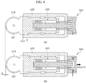
- a hydraulic pressure is injected into, for example, a later-described plunger 524 of the roller assembly 520, so that the fixed shaft 522 of the roller assembly 520 may be caused to retreat and the roller 510 connected to the fixed shaft 522 may be caused to retreat.
- the separation of the roller 510 and the slab may be simply carried out.
- the segments 500 in accordance with an exemplary embodiment are fixed roll gap-type segments having a fixed distance between the first frame 530a and the second frame 530b, have a strong structure, and are easily handled, and even in an emergent situation, the slab and the casting apparatus may be easily separated in order to recover the casting apparatus. Specifically, in an emergent situation, the slab and rollers may be easily separated using the roller assemblies 520.
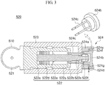
- FIG. 3 is a schematic view of a roller assembly according to an exemplary embodiment
- FIG. 4 is an operational view of a roller assembly according to an exemplary embodiment.
- (a) of FIG. 4 is an operational view of a roller assembly illustrating a state in which a roller in a movement path is supported during a normal operation
- (b) of FIG. 4 is an operational view of the roller assembly illustrating a state in which the roller retreats from the movement path by the roller assembly during emergency.
- a roller assembly 520 in accordance with an exemplary embodiment may be used not only as a supporting and retreating device for the roller of the segment 500 in a casting apparatus, but also used as a supporting and retreating device for the roller which is installed in the movement path of equipment for various to-be-treated materials and guides the movement of the to-be-treated material.
- the roller assembly 520 in accordance with an exemplary embodiment is a roller assembly 520 which is capable of causing a roller 510, arranged in the movement path of a to-be-treated material such as a slab, to retreat from the movement path of the slab, the roller assembly including: a supporter 521 that supports the roller 510 in an axially rotatable manner; a fixed shaft 522 attached to the rear surface of the supporter 521 and having at least a stretchable portion; and a body 523 attached to the rear surface side of the supporter 521 so as to surround the fixed shaft 522 and fixed to a predetermined frame which is installed to surround the movement path of the slab; and a plunger 524 attached to pass through the rear surface of the body 523 and connected to the rear end of the fixed shaft 522.
- the plunger 524 may be formed so that at least a portion thereof may advance and retreat by using a hydraulic pressure with respect to the movement path of the slab, and the fixed shaft 522 may cause the roller 510 to retreat from the movement path of the slab while retreating by the plunger 524.
- the roller 510 when casting a thick slab, and when various emergent situations occur, the roller 510 may be forcibly spaced apart from the slab, so that the subsequent repair and recovery may be easy.
- extension direction of the movement path and the arrangement direction of the rollers may be variously different from the installation direction and the extension direction of components of the roller assembly 520.
- the supporter 521 may support the roller 510 disposed in the movement path of the slab in an axially rotatable manner.
- the supporter 521 may be formed in various shapes in which end sections of the roller 510 can be easily attached and supported.
- the supporter 521 may have: one side which faces frontward, is formed in a disk shape having a smaller diameter than the roller 510, and faces the end sections of the roller 510 in the left-right direction; and the other side which faces rearward, is formed in a bar shape, and faces the front surface of the fixed shaft 522 in the front-rear direction.
- the one side of the supporter 521 may have a central portion to which the roller 510 is attached in an axially rotatable manner, and the other side may have a rear surface to which the fixed shaft 522 is attached.
- the fixed shaft 522 may be attached to the rear surface of the supporter 521 in the front-rear direction.
- the fixed shaft 522 may be formed such that a plurality of split-type or separabe-type shafts are coupled to each other. Meanwhile, when the roller 510 comes into close contact with and rolls the slab, a reaction force due to the ferro-static pressure of the slab may be transferred to the fixed shaft 522 in a form of axial force via the supporter 521.
- At least a portion of the fixed shaft 522 may be formed to be stretchable in the front-rear direction so as to receive and dissipate the axial force and prevent damage due to the axial force.
- the fixed shaft 522 may include: a first shaft 522a extending in the front-rear direction and attached to the rear surface of the supporter 521; a first shaft hole penetrating through the rear surface of the first shaft 522a and extending in the front-rear direction; a first shaft cover 522b attached to the rear surface of the first shaft 522a; a second shaft 552c which penetrates the first shaft cover 522b in the front-rear direction, and has one side disposed inside the first shaft hole and spaced apart from the inner surface of the first shaft hole, and the other side attached to penetrate through the center of the rear surface of the body 523 in the front-rear direction; a ring-like protrusion protruding on the one-side outer circumferential surface of the second shaft 522c; elastic members, such as, a plurality of cup springs 522d, supported on the one-side outer circumferential surface of the second shaft 522c in front of the ring-like protrusion and contacting each other in the front-re
- the second shaft 522c is attached to the rear surface of the body 523 and the movement thereof in the front-rear direction is constrained, and the first shaft 522a may advance and retreat while supported by the outer circumferential surface of the second shaft 522c.
- the first shaft hole and the plurality of cup spring 522d may guide and accommodate the advancing and retreating movement of the first shaft 522a.
- the fixed shaft 522 is stretchable in the front-rear direction, and prevent the damage due to the axial force while receiving and dissipating the axial force.
- the body 523 may extend in the front-rear direction, the inside thereof may be open frontward, and the body may be attached to the rear surface side of the supporter 521 so as to surround the fixed shaft 522.
- the body 523 may have a rectangular column shape, but exemplary embodiments are not particularly limited thereto.
- the body 523 is disposed so as to be spaced apart from the rear side of the supporter 521 rearward, and the fixed shaft 522 may be installed inside the body 523.
- the second shaft 522c of the fixed shaft 522 may be attached to and supported by the rear surface of the body 523.
- the fixed shaft 522 may be accommodated inside the body 523 and the fixed shaft 522 may be supported by the inner surface of the body 523.
- the fixed shaft 522 may be disposed so as to penetrate the inside of the body 523 in the front-rear direction.
- the outer surface of the body 523 may be attached to and supported by the first frame 530a or the second frame 530b.
- the front end of the body 523 may be spaced apart a predetermined distance d from the rear surface of the supporter 521.
- the plunger 524 may be attached passing through the rear surface of the body 523 and connected to the rear end of the fixed shaft 522.
- the plunger 524 may be attached by connecting the body 523 and the fixed shaft 522.
- At least a portion of the plunger 524 may be formed so as to advance and retreat with respect to the movement path of the slab, and at least a portion of the plunger may be formed so as to retreat by using hydraulic pressure and cause the fixed shaft 522 to retreat from the movement path of the slab.
- the hydraulic pressure may be applied to the fixed shaft 522 in a direction away from the slab via the plunger 524, and accordingly, the fixed shaft 522 retreats a predetermined distance and pulls the supporter 521 rearward, so that the roller 510 may be spaced apart from and separated from the slab while retreating from the movement path of the slab. That is, the plunger 524 functions to separate the roller 510 from the slab.
- the plunger 524 may include: a hollow outer cylinder 524a having a front end attached to the rear surface of the body 523, and an inner stepped portion 524e formed in the inner circumferential surface thereof, the inner diameter of a rear side from the inner stepped portion 524e being larger than the inner diameter of a front side thereof; an inner cylinder 524b attached to pass through the center of the outer cylinder 524a and having an outer stepped portion 524f on the outer circumferential surface thereof, the outer circumferential surface thereof being in contact with the inner circumferential surface of the outer cylinder 524a; a plurality of connecting shafts 524c formed to protrude from the front end of the inner cylinder 524b, passing through the rear surface of the body 523, and connected to the rear end of the fixed shaft 522, for example, to the first shaft cover 522b; an injection port 524d attached to pass through the outer cylinder 524a so as to form a hydraulic pressure by injecting a fluid into a hydraulic pressure space 524g formed
- the outer cylinder 524a may extend in the front-rear direction and be formed in a hollow cylinder shape.
- the inner cylinder 524b may pass through the center of the outer cylinder 524a and be attached in movable manner in the front-rear direction.
- the inner cylinder 524b may have an inner portion open frontward, be disposed inside the outer cylinder 524a, and may accommodate therein the other side of the second shaft 522c.
- Mutually facing outer circumferential surface and inner circumferential surface of the outer cylinder 524a and inner cylinder 524b may be in contact or close contact with each other, and a hydraulic pressure space 524g may be formed. Meanwhile, an inclined surface may be formed on the one-side outer stepped portion 524f of the inner cylinder 524b contacting the injection port 524d so that the fluid may easily be injected to apply hydraulic pressure.
- connection shafts 524c may be formed in bolt shapes, the front end thereof may be attached to the rear end of the fixed shaft 522, and the rear end thereof may be connected to the front end of the inner cylinder 524b and move linked to the movement of the inner cylinder 524b. Accordingly, the fixed shaft 522 and the inner cylinder 524b may move together in the same direction via the connection shafts 524c.
- the injection port valve may apply the hydraulic pressure step by step by opening the injection port 524d in an intermittent manner when the fluid for the hydraulic pressure is injected. That is, the hydraulic pressure may be applied step by step even when the hydraulic space 524g is a single connected space, and accordingly, a suitable amount of the fluid may be divided and supplied to the hydraulic space 524g according to the fused state of the roller 510 and the slab.
- the inner cylinder 524b retreats while the hydraulic space 524g is expanded, and accordingly, the connection shaft 524c retreats and causes the fixed shaft 522 to retreat.
- the movement of the fixed shaft 522 may be received by the first shaft hole and the plurality of cup springs 522d.
- the roller 510 may also retreat by the gap d.
- the hydraulic pressure applied to the injection space 524g for the retreatment of the roller 510 may be sufficiently applied by a portable hydraulic pressure application device such as a grease gun.
- the roller 510 is forcibly spaced apart from a slab due to the retreatment of the roller 510, and the roller fused to the slab may be separated from the slab. Accordingly, in a situation in which the slag and the roller 510 are fused during molten steel outflow, the roller 510 and the slab may easily be separated from each other without damage to the apparatus, and thereafter the recovery operation of the casting apparatus may easily be carried out.
- a roller separating method for a casting apparatus in accordance with an exemplary embodiment is a method for separating a roller from a slab in a movement path, the method including: drawing a slab from a mold; guiding the movement of the slab drawn from the mold using a plurality of segments consecutively arranged along the movement path; and causing a plurality of roller assemblies, which are attached to a plurality of rollers provided to the segments, and have at least a portion formed so as to advance and retreat with respect to the movement path of the slab, to retreat from the movement path of the slab and causing the rollers supported by the roller assemblies to be spaced apart from the slab when the slab is being moved or stops.
- a casting apparatus in accordance with the above-described exemplary embodiment is prepared, and a melt, such as a molten steel, is injected into the mold 30 and solidified into a slab, and the slab is continuously drawn downward.
- a melt such as a molten steel
- the movement of the slab is guided by using the rollers 510.
- various emergent situations such as outflow of the molten steel, or retention of slabs, casting is stopped. At this point, the slab may be in a stopped state or in a moving state.
- a hydraulic pressure is formed by injecting a fluid into a plunger 524 of the roller assembly 520, and causes a portion of the roller assembly 520, for example, a fixed shaft 522 to retreat.
- the roller 510 supported by a supporter 521 may be spaced apart from the movement path of the slab
- the hydraulic pressure may be applied into the plunger 524 in a intermittent manner, and an operation may be efficiently carried out by applying a required amount of hydraulic pressure.
Landscapes
- Engineering & Computer Science (AREA)
- Mechanical Engineering (AREA)
- Continuous Casting (AREA)
- Actuator (AREA)
- Casting Devices For Molds (AREA)
Claims (10)
- Rollenanordnung (520), umfassend:eine Haltevorrichtung (521), die so konfiguriert ist, dass sie eine Rolle (510) drehbeweglich abstützt, die auf einer Bewegungsbahn (40) eines zu bearbeitenden Materials angeordnet ist;eine feste Welle (522), die an einer Rückfläche der Haltevorrichtung (521) angebracht ist und einen dehnbaren Teil aufweist;einen Körper (523), der an der der hinteren Oberfläche der Haltevorrichtung (521) so angebracht ist, (522) dass er die feststehende Welle umschließt; undeinen Kolben (524), der angebracht ist, um den Körper (523) und die feststehende Welle (522) zu verbinden und so ausgebildet ist, dass sich ein Teil davon in Bezug auf die Bewegungsbahn (40) vor- und zurückbewegt,
wobei die feststehende Welle (522) eine erste Welle (522a), eine zweite Welle (522c) und elastische Elemente (522d) umfasst, um eine Reaktionskraft aufzunehmen und abzuleiten, die durch das zu bearbeitende Material verursacht wird,wobei die erste Welle (522a) an der Rückfläche der Haltevorrichtung (521) angebracht ist,die zweite Welle (522c) an einer Stelle die Rückfläche der ersten Welle (522a) durchdringt, um eine Vorwärts- und Rückwärtsbewegung der ersten Welle (522a) zu unterstützen, und die andere Seite an einer Rückfläche des Körpers (523) angebracht ist undsich die elastischen Elemente (522d) an einer einseitigen äußeren Umfangsfläche der zweiten Welle (522c) abstützen und dehnbar sind, um die Vorwärts-/Rückwärtsbewegung der ersten Welle (522a) aufzunehmen. - Rollenanordnung (520) nach Anspruch 1, wobei der Kolben (524) so ausgebildet ist, dass ein Teil davon während der Rückwärtsbewegung mithilfe eines Hydraulikdrucks veranlasst, dass sich die erste Welle (522a) auf der Bewegungsbahn (40) zurückbewegt.
- Rollenanordnung (520) nach Anspruch 1, wobei der Kolben (524) durch eine Rückfläche des Gehäuses (523) verläuft und mit einer Rückfläche der ersten Welle (522a) verbunden ist.
- Rollenanordnung (520) nach Anspruch 1, wobei der Kolben (524) Folgendes umfasst:einen hohlen Außenzylinder (524a), dessen vorderes Ende an einer Rückfläche des Gehäuses (523) angebracht ist, und einen inneren abgestuften Teil (524e), der in eine innere Umfangsfläche davon eingearbeitet ist, wobei der Innendurchmesser eines hinteren Endes desselben von dem inneren abgestuften Teil (524e) größer ist als der Innendurchmesser eines vorderen Endes desselben;einen inneren Zylinder (524b), der so angebracht ist, dass er durch den Außenzylinder (524a) durchdringt und einen äußeren abgestuften Teil (524f) an seiner äußeren Umfangsfläche aufweist, wobei seine äußere Umfangsfläche mit der inneren Umfangsfläche des Außenzylinders (524a) in Kontakt steht;eine Verbindungswelle (524c),die so ausgebildet ist, dass sie über ein vorderes Ende des Innenzylinders (524b) hinausragt, durch die Rückfläche des Gehäuses (523) hindurchgeht und mit einer Rückfläche der ersten Welle (522a) verbunden ist; undeine Einspritzöffnung (524d), die so angebracht ist, dass sie durch den Außenzylinder (524a) verläuft, um einen Hydraulikdruck zu erzeugen, indem eine Flüssigkeit in einen Hydraulikdruckraum (524g) eingespritzt wird, der durch den inneren abgestuften Teil (524e) und den äußeren abgestuften Teil (524f) gebildet wird.
- Rollenanordnung (520) nach Anspruch 4, wobei der Kolben (524) ferner ein Einspritzöffnungsventil umfasst, das an der Einspritzöffnung angebracht ist und intermittierend geöffnet wird.
- Gießvorrichtung zum Formgießen einer Bramme unter Verwendung einer Form,wobei die Gießvorrichtung eine Vielzahl von Abschnitten umfasst, die nacheinander unter der Form angeordnet sind, um eine Bewegung der Bramme zu führen, die aus der Form entnommen wird, unddie Abschnitte Folgendes umfassen:eine Vielzahl von Rollen (510), die nacheinander entlang einer Bewegungsbahn (40) angeordnet und einem Abstand zueinander angeordnet sind, dass sie sich einander gegenüberstehen, wobei sich die Bewegungsbahn (40) der Bramme dazwischen befindet; undeine Vielzahl von Rollenanordnungen nach Anspruch 1, die an der Vielzahl von Rollen (510) angebracht sind und einen Teil aufweisen, der sich relativ zur Bewegungsbahn (40) vor- und zurückzubewegen kann.
- Gießvorrichtung nach Anspruch 6, wobeidie Abschnitte einen ersten Rahmen (530a) und einen zweiten Rahmen (530b) umfassen, die in einem Abstand zueinander angeordnet sind, dass sie einander gegenüberstehen, wobei sich die Bewegungsbahn (40) dazwischen befindet, wobei der erste Rahmen (530a) und der zweite Rahmen (530b) eine Vielzahl von Rollenanordnungen tragen unddie Rollenanordnungen so ausgebildet sind, dass ein Teil davon dazu in der Lage ist, die Rollen (510) während des Rückwärtsfahrens mittels hydraulischem Druck von der Bewegungsbahn (40)zu bewegen.
- Rollentrennverfahren zum Trennen einer Rolle (510) von einer Bramme auf einer Bewegungsbahn (40), wobei das Verfahren Folgendes einschließt:Entnahme der Bramme aus einer Form;Führen einer Bewegung der Bramme, die aus einer Form entnommen wird, unter Verwendung einer Vielzahl von Abschnitten, die nacheinander entlang der Bewegungsbahn (40) angeordnet sind; undZurückbewegen einer Vielzahl von Rollenanordnungen aus der Bewegungsbahn (40) nach einem der Ansprüche 1-5, die an einer Vielzahl von in den Abschnitten vorgesehenen Rollen (510) angebracht sind und einen Teil aufweisen, der so ausgebildet ist, dass er sich in Bezug auf die Bewegungsbahn (40) der Bramme vor- und zurückbewegt, und Bewegung der Rollen (510), die von den Rollenanordnungen getragen werden, von der Bramme weg, wenn die Bramme in Bewegung gesetzt wird oder stoppt,wobei eine Reaktionskraft, die durch einen ferrostatischen Druck der Bramme während einer Bewegung der Bramme verursacht wird, durch das Dehnen der elastischen Elemente (522d) einer feststehenden Welle (522) abgeleitet wird, die in den Rollenanordnungen vorgesehen ist.
- Rollentrennverfahren nach Anspruch 8, wobei das Veranlassen des Abstands der Rollen (510) von der Bramme Folgendes umfasst:Aufbringen eines Hydraulikdrucks auf die Rollenanordnungen und Zurückbewegen eines Teils der Rollenanordnungen von der Bewegungsbahn (40) ; undZurückbewegen der Rollen, die mit dem Teil der Rollenanordnungen verbunden sind, von der Bewegungsbahn (40).
- Rollentrennverfahren nach Anspruch 9, wobei das Zurückbewegen der Rollen (510) von der Bramme , um diese von der Bramme zu beabstanden, ferner das periodische Aufbringen eines Hydraulikdrucks umfasst, wenn der Hydraulikdruck auf die Rollenanordnungen aufgebracht wird.
Applications Claiming Priority (2)
| Application Number | Priority Date | Filing Date | Title |
|---|---|---|---|
| KR1020170101208A KR101949701B1 (ko) | 2017-08-09 | 2017-08-09 | 롤러 조립체, 주조 장치 및 이의 롤러 분리 방법 |
| PCT/KR2018/009039 WO2019031849A1 (ko) | 2017-08-09 | 2018-08-08 | 롤러 조립체, 주조 장치 및 이의 롤러 분리 방법 |
Publications (3)
| Publication Number | Publication Date |
|---|---|
| EP3666417A1 EP3666417A1 (de) | 2020-06-17 |
| EP3666417A4 EP3666417A4 (de) | 2020-06-17 |
| EP3666417B1 true EP3666417B1 (de) | 2021-10-06 |
Family
ID=65271328
Family Applications (1)
| Application Number | Title | Priority Date | Filing Date |
|---|---|---|---|
| EP18843075.5A Active EP3666417B1 (de) | 2017-08-09 | 2018-08-08 | Rollenanordnung, giessvorrichtung und rollentrennverfahren dafür |
Country Status (7)
| Country | Link |
|---|---|
| US (1) | US11141781B2 (de) |
| EP (1) | EP3666417B1 (de) |
| JP (1) | JP6972301B2 (de) |
| KR (1) | KR101949701B1 (de) |
| CN (1) | CN110997180B (de) |
| BR (1) | BR112020002585B1 (de) |
| WO (1) | WO2019031849A1 (de) |
Family Cites Families (18)
| Publication number | Priority date | Publication date | Assignee | Title |
|---|---|---|---|---|
| US3891025A (en) | 1972-06-29 | 1975-06-24 | Schloemann Siemag Ag | Apparatus for withdrawing a casting and feeding a dummy bar in a continuous casting machine for steel |
| JPS53142522U (de) * | 1977-04-15 | 1978-11-10 | ||
| IT1079045B (it) | 1977-05-16 | 1985-05-08 | Syva Co | Analisi imuunologica fluorescente a doppio ricettore |
| JPH08108256A (ja) * | 1994-10-06 | 1996-04-30 | Nippon Steel Corp | 連鋳機における鋳片ガイドロールの迅速型替え装置 |
| JPH09220654A (ja) * | 1996-02-15 | 1997-08-26 | Kawasaki Steel Corp | 連続鋳造機のローラエプロン |
| DE10024508A1 (de) * | 2000-05-18 | 2001-11-22 | Sms Demag Ag | Verfahren und Anlage zum Stranggießen von Brammen, insbesondere von Dünnbrammen mit vergleichsweise hohen Gießgeschwindigkeiten |
| KR100596474B1 (ko) * | 2004-09-07 | 2006-07-03 | 주식회사 포스코 | 연속주조기의 구동롤 받침 프레임 |
| DE102005039473A1 (de) * | 2005-08-20 | 2007-02-22 | Sms Demag Ag | Vorrichtung für ein schnelles Verbinden oder ein schnelles Lösen von zwei grossen, schweren Bauteilen für den Hüttenwerksbetrieb, insbesondere für eine Stahl-Stranggiessmaschine |
| AT502694B1 (de) * | 2005-10-20 | 2007-10-15 | Voest Alpine Industrienanlagen | Strangführungsrolle |
| KR100862779B1 (ko) * | 2007-04-11 | 2008-10-13 | 주식회사 포스코 | 연속주조 세그멘트의 드라이브 롤 |
| DE102008004915A1 (de) * | 2008-01-18 | 2009-07-23 | Sms Demag Ag | Treibrichtsystem für Stranggießanlagen |
| KR101372640B1 (ko) | 2011-12-27 | 2014-03-11 | 주식회사 포스코 | 분리형 세그먼트 및 이를 이용한 롤 교환 방법 |
| KR20140002097A (ko) | 2012-06-26 | 2014-01-08 | 주식회사 포스코 | 세그먼트를 포함하는 연속주조기 |
| CN103691900B (zh) * | 2013-12-31 | 2015-10-28 | 一重集团大连设计研究院有限公司 | 垂直铸机的推拉式导向移坯装置 |
| KR101632347B1 (ko) | 2014-10-06 | 2016-06-21 | 주식회사 포스코 | 세그멘트 가이드 롤 교환장치 및 세그멘트 가이드 롤 교환 방법 |
| TWM495400U (zh) * | 2014-10-22 | 2015-02-11 | Ren-Zhe Hong | 珠子鎖防撬鎖具組 |
| AT516412B1 (de) | 2014-10-28 | 2017-07-15 | Primetals Technologies Austria GmbH | Strangführungsrolleneinheit für eine Stranggießmaschine |
| KR101779152B1 (ko) | 2015-12-04 | 2017-09-26 | 주식회사 포스코 | 주조 방법 및 주조 설비 |
-
2017
- 2017-08-09 KR KR1020170101208A patent/KR101949701B1/ko active Active
-
2018
- 2018-08-08 WO PCT/KR2018/009039 patent/WO2019031849A1/ko not_active Ceased
- 2018-08-08 US US16/637,495 patent/US11141781B2/en active Active
- 2018-08-08 JP JP2020505774A patent/JP6972301B2/ja active Active
- 2018-08-08 EP EP18843075.5A patent/EP3666417B1/de active Active
- 2018-08-08 CN CN201880051573.3A patent/CN110997180B/zh active Active
- 2018-08-08 BR BR112020002585-2A patent/BR112020002585B1/pt active IP Right Grant
Also Published As
| Publication number | Publication date |
|---|---|
| EP3666417A1 (de) | 2020-06-17 |
| BR112020002585A2 (pt) | 2020-07-28 |
| BR112020002585B1 (pt) | 2023-03-21 |
| US20200215605A1 (en) | 2020-07-09 |
| CN110997180B (zh) | 2021-11-16 |
| US11141781B2 (en) | 2021-10-12 |
| JP2020529924A (ja) | 2020-10-15 |
| JP6972301B2 (ja) | 2021-11-24 |
| KR101949701B1 (ko) | 2019-02-19 |
| CN110997180A (zh) | 2020-04-10 |
| WO2019031849A1 (ko) | 2019-02-14 |
| EP3666417A4 (de) | 2020-06-17 |
Similar Documents
| Publication | Publication Date | Title |
|---|---|---|
| EP2828019B1 (de) | Vorrichtung und verfahren zum kontinuierlichen stranggiessen eines grossformatigen stahlstrangs | |
| JP2007532346A (ja) | プラスチック物品を圧縮成形するための方法および装置 | |
| EP3666417B1 (de) | Rollenanordnung, giessvorrichtung und rollentrennverfahren dafür | |
| US3559720A (en) | Continuous casting apparatus having a two part separable mold | |
| KR101442660B1 (ko) | 가이드 롤의 베어링 제거장치 | |
| KR101260056B1 (ko) | 절단설 제거 장치 | |
| KR102326862B1 (ko) | 롤러 장치 및 주조 설비 | |
| KR101696828B1 (ko) | 회전체 구동장치 및 이를 포함하는 연속주조용 세그먼트 | |
| CA2262677A1 (en) | Guide segment support system for continuous casting | |
| US5152334A (en) | Guide roll assembly and method of guiding cast strand | |
| EP3546089B1 (de) | Stranggiessvorrichtung mit doppelter walze | |
| EP3600721B1 (de) | Anlage und verfahren zum semi-kontinuierlichen stranggiessen von blocksträngen | |
| KR101630962B1 (ko) | 연속주조용 세그먼트 | |
| KR101259373B1 (ko) | 연속주조기 세그먼트 장치 | |
| JP3794888B2 (ja) | 連続鋳造材の切断方法 | |
| KR102020897B1 (ko) | 연속 주조설비의 세그먼트 장치 | |
| KR101510277B1 (ko) | 슬라브의 측면을 지지하는 롤러장치 | |
| KR20100034948A (ko) | 열간압연설비 | |
| KR20240107920A (ko) | 워크롤의 제조 장치 및 워크롤의 제조 방법 | |
| JP2013230487A (ja) | モールドクランプ装置及びそれを用いた連続鋳造設備 | |
| KR101511724B1 (ko) | 가이드 롤 장치 | |
| US6634416B1 (en) | Device and process for fast changing of parts of the bar guide in continuous-casting plants | |
| KR20110000376A (ko) | 연속주조 슬라브의 중심편석 저감방법 | |
| CN120619310A (zh) | 一种高效率金属零部件连续铸造设备以及工作方法 | |
| KR20020078828A (ko) | 연속주조 세그멘트롤의 리덕션 장치 |
Legal Events
| Date | Code | Title | Description |
|---|---|---|---|
| STAA | Information on the status of an ep patent application or granted ep patent |
Free format text: STATUS: THE INTERNATIONAL PUBLICATION HAS BEEN MADE |
|
| PUAI | Public reference made under article 153(3) epc to a published international application that has entered the european phase |
Free format text: ORIGINAL CODE: 0009012 |
|
| STAA | Information on the status of an ep patent application or granted ep patent |
Free format text: STATUS: REQUEST FOR EXAMINATION WAS MADE |
|
| 17P | Request for examination filed |
Effective date: 20200204 |
|
| A4 | Supplementary search report drawn up and despatched |
Effective date: 20200417 |
|
| AK | Designated contracting states |
Kind code of ref document: A1 Designated state(s): AL AT BE BG CH CY CZ DE DK EE ES FI FR GB GR HR HU IE IS IT LI LT LU LV MC MK MT NL NO PL PT RO RS SE SI SK SM TR |
|
| AX | Request for extension of the european patent |
Extension state: BA ME |
|
| DAV | Request for validation of the european patent (deleted) | ||
| DAX | Request for extension of the european patent (deleted) | ||
| GRAP | Despatch of communication of intention to grant a patent |
Free format text: ORIGINAL CODE: EPIDOSNIGR1 |
|
| STAA | Information on the status of an ep patent application or granted ep patent |
Free format text: STATUS: GRANT OF PATENT IS INTENDED |
|
| INTG | Intention to grant announced |
Effective date: 20210312 |
|
| GRAS | Grant fee paid |
Free format text: ORIGINAL CODE: EPIDOSNIGR3 |
|
| GRAA | (expected) grant |
Free format text: ORIGINAL CODE: 0009210 |
|
| STAA | Information on the status of an ep patent application or granted ep patent |
Free format text: STATUS: THE PATENT HAS BEEN GRANTED |
|
| AK | Designated contracting states |
Kind code of ref document: B1 Designated state(s): AL AT BE BG CH CY CZ DE DK EE ES FI FR GB GR HR HU IE IS IT LI LT LU LV MC MK MT NL NO PL PT RO RS SE SI SK SM TR |
|
| REG | Reference to a national code |
Ref country code: GB Ref legal event code: FG4D |
|
| REG | Reference to a national code |
Ref country code: CH Ref legal event code: EP Ref country code: AT Ref legal event code: REF Ref document number: 1435782 Country of ref document: AT Kind code of ref document: T Effective date: 20211015 |
|
| REG | Reference to a national code |
Ref country code: IE Ref legal event code: FG4D |
|
| REG | Reference to a national code |
Ref country code: DE Ref legal event code: R096 Ref document number: 602018024824 Country of ref document: DE |
|
| REG | Reference to a national code |
Ref country code: LT Ref legal event code: MG9D |
|
| REG | Reference to a national code |
Ref country code: NL Ref legal event code: MP Effective date: 20211006 |
|
| PG25 | Lapsed in a contracting state [announced via postgrant information from national office to epo] |
Ref country code: RS Free format text: LAPSE BECAUSE OF FAILURE TO SUBMIT A TRANSLATION OF THE DESCRIPTION OR TO PAY THE FEE WITHIN THE PRESCRIBED TIME-LIMIT Effective date: 20211006 Ref country code: LT Free format text: LAPSE BECAUSE OF FAILURE TO SUBMIT A TRANSLATION OF THE DESCRIPTION OR TO PAY THE FEE WITHIN THE PRESCRIBED TIME-LIMIT Effective date: 20211006 Ref country code: FI Free format text: LAPSE BECAUSE OF FAILURE TO SUBMIT A TRANSLATION OF THE DESCRIPTION OR TO PAY THE FEE WITHIN THE PRESCRIBED TIME-LIMIT Effective date: 20211006 Ref country code: BG Free format text: LAPSE BECAUSE OF FAILURE TO SUBMIT A TRANSLATION OF THE DESCRIPTION OR TO PAY THE FEE WITHIN THE PRESCRIBED TIME-LIMIT Effective date: 20220106 |
|
| PG25 | Lapsed in a contracting state [announced via postgrant information from national office to epo] |
Ref country code: IS Free format text: LAPSE BECAUSE OF FAILURE TO SUBMIT A TRANSLATION OF THE DESCRIPTION OR TO PAY THE FEE WITHIN THE PRESCRIBED TIME-LIMIT Effective date: 20220206 Ref country code: SE Free format text: LAPSE BECAUSE OF FAILURE TO SUBMIT A TRANSLATION OF THE DESCRIPTION OR TO PAY THE FEE WITHIN THE PRESCRIBED TIME-LIMIT Effective date: 20211006 Ref country code: PT Free format text: LAPSE BECAUSE OF FAILURE TO SUBMIT A TRANSLATION OF THE DESCRIPTION OR TO PAY THE FEE WITHIN THE PRESCRIBED TIME-LIMIT Effective date: 20220207 Ref country code: PL Free format text: LAPSE BECAUSE OF FAILURE TO SUBMIT A TRANSLATION OF THE DESCRIPTION OR TO PAY THE FEE WITHIN THE PRESCRIBED TIME-LIMIT Effective date: 20211006 Ref country code: NO Free format text: LAPSE BECAUSE OF FAILURE TO SUBMIT A TRANSLATION OF THE DESCRIPTION OR TO PAY THE FEE WITHIN THE PRESCRIBED TIME-LIMIT Effective date: 20220106 Ref country code: NL Free format text: LAPSE BECAUSE OF FAILURE TO SUBMIT A TRANSLATION OF THE DESCRIPTION OR TO PAY THE FEE WITHIN THE PRESCRIBED TIME-LIMIT Effective date: 20211006 Ref country code: LV Free format text: LAPSE BECAUSE OF FAILURE TO SUBMIT A TRANSLATION OF THE DESCRIPTION OR TO PAY THE FEE WITHIN THE PRESCRIBED TIME-LIMIT Effective date: 20211006 Ref country code: HR Free format text: LAPSE BECAUSE OF FAILURE TO SUBMIT A TRANSLATION OF THE DESCRIPTION OR TO PAY THE FEE WITHIN THE PRESCRIBED TIME-LIMIT Effective date: 20211006 Ref country code: GR Free format text: LAPSE BECAUSE OF FAILURE TO SUBMIT A TRANSLATION OF THE DESCRIPTION OR TO PAY THE FEE WITHIN THE PRESCRIBED TIME-LIMIT Effective date: 20220107 Ref country code: ES Free format text: LAPSE BECAUSE OF FAILURE TO SUBMIT A TRANSLATION OF THE DESCRIPTION OR TO PAY THE FEE WITHIN THE PRESCRIBED TIME-LIMIT Effective date: 20211006 |
|
| REG | Reference to a national code |
Ref country code: DE Ref legal event code: R097 Ref document number: 602018024824 Country of ref document: DE |
|
| PG25 | Lapsed in a contracting state [announced via postgrant information from national office to epo] |
Ref country code: SM Free format text: LAPSE BECAUSE OF FAILURE TO SUBMIT A TRANSLATION OF THE DESCRIPTION OR TO PAY THE FEE WITHIN THE PRESCRIBED TIME-LIMIT Effective date: 20211006 Ref country code: SK Free format text: LAPSE BECAUSE OF FAILURE TO SUBMIT A TRANSLATION OF THE DESCRIPTION OR TO PAY THE FEE WITHIN THE PRESCRIBED TIME-LIMIT Effective date: 20211006 Ref country code: RO Free format text: LAPSE BECAUSE OF FAILURE TO SUBMIT A TRANSLATION OF THE DESCRIPTION OR TO PAY THE FEE WITHIN THE PRESCRIBED TIME-LIMIT Effective date: 20211006 Ref country code: EE Free format text: LAPSE BECAUSE OF FAILURE TO SUBMIT A TRANSLATION OF THE DESCRIPTION OR TO PAY THE FEE WITHIN THE PRESCRIBED TIME-LIMIT Effective date: 20211006 Ref country code: DK Free format text: LAPSE BECAUSE OF FAILURE TO SUBMIT A TRANSLATION OF THE DESCRIPTION OR TO PAY THE FEE WITHIN THE PRESCRIBED TIME-LIMIT Effective date: 20211006 Ref country code: CZ Free format text: LAPSE BECAUSE OF FAILURE TO SUBMIT A TRANSLATION OF THE DESCRIPTION OR TO PAY THE FEE WITHIN THE PRESCRIBED TIME-LIMIT Effective date: 20211006 |
|
| PLBE | No opposition filed within time limit |
Free format text: ORIGINAL CODE: 0009261 |
|
| STAA | Information on the status of an ep patent application or granted ep patent |
Free format text: STATUS: NO OPPOSITION FILED WITHIN TIME LIMIT |
|
| 26N | No opposition filed |
Effective date: 20220707 |
|
| REG | Reference to a national code |
Ref country code: DE Ref legal event code: R081 Ref document number: 602018024824 Country of ref document: DE Owner name: POSCO CO., LTD, POHANG-SI, KR Free format text: FORMER OWNER: POSCO, POHANG-SI, GYEONGSANGBUK-DO, KR Ref country code: DE Ref legal event code: R081 Ref document number: 602018024824 Country of ref document: DE Owner name: POSCO CO., LTD, POHANG- SI, KR Free format text: FORMER OWNER: POSCO, POHANG-SI, GYEONGSANGBUK-DO, KR Ref country code: DE Ref legal event code: R081 Ref document number: 602018024824 Country of ref document: DE Owner name: POSCO HOLDINGS INC., KR Free format text: FORMER OWNER: POSCO, POHANG-SI, GYEONGSANGBUK-DO, KR |
|
| PG25 | Lapsed in a contracting state [announced via postgrant information from national office to epo] |
Ref country code: AL Free format text: LAPSE BECAUSE OF FAILURE TO SUBMIT A TRANSLATION OF THE DESCRIPTION OR TO PAY THE FEE WITHIN THE PRESCRIBED TIME-LIMIT Effective date: 20211006 |
|
| REG | Reference to a national code |
Ref country code: GB Ref legal event code: 732E Free format text: REGISTERED BETWEEN 20221027 AND 20221102 |
|
| PG25 | Lapsed in a contracting state [announced via postgrant information from national office to epo] |
Ref country code: SI Free format text: LAPSE BECAUSE OF FAILURE TO SUBMIT A TRANSLATION OF THE DESCRIPTION OR TO PAY THE FEE WITHIN THE PRESCRIBED TIME-LIMIT Effective date: 20211006 |
|
| REG | Reference to a national code |
Ref country code: AT Ref legal event code: UEP Ref document number: 1435782 Country of ref document: AT Kind code of ref document: T Effective date: 20211006 |
|
| PG25 | Lapsed in a contracting state [announced via postgrant information from national office to epo] |
Ref country code: MC Free format text: LAPSE BECAUSE OF FAILURE TO SUBMIT A TRANSLATION OF THE DESCRIPTION OR TO PAY THE FEE WITHIN THE PRESCRIBED TIME-LIMIT Effective date: 20211006 |
|
| REG | Reference to a national code |
Ref country code: CH Ref legal event code: PL |
|
| REG | Reference to a national code |
Ref country code: AT Ref legal event code: PC Ref document number: 1435782 Country of ref document: AT Kind code of ref document: T Owner name: POSCO CO., LTD, KR Effective date: 20230228 |
|
| REG | Reference to a national code |
Ref country code: DE Ref legal event code: R081 Ref document number: 602018024824 Country of ref document: DE Owner name: POSCO CO., LTD, POHANG-SI, KR Free format text: FORMER OWNER: POSCO HOLDINGS INC., SEOUL, KR Ref country code: DE Ref legal event code: R081 Ref document number: 602018024824 Country of ref document: DE Owner name: POSCO CO., LTD, POHANG- SI, KR Free format text: FORMER OWNER: POSCO HOLDINGS INC., SEOUL, KR |
|
| PG25 | Lapsed in a contracting state [announced via postgrant information from national office to epo] |
Ref country code: LU Free format text: LAPSE BECAUSE OF NON-PAYMENT OF DUE FEES Effective date: 20220808 Ref country code: LI Free format text: LAPSE BECAUSE OF NON-PAYMENT OF DUE FEES Effective date: 20220831 Ref country code: CH Free format text: LAPSE BECAUSE OF NON-PAYMENT OF DUE FEES Effective date: 20220831 |
|
| REG | Reference to a national code |
Ref country code: BE Ref legal event code: MM Effective date: 20220831 |
|
| PG25 | Lapsed in a contracting state [announced via postgrant information from national office to epo] |
Ref country code: IE Free format text: LAPSE BECAUSE OF NON-PAYMENT OF DUE FEES Effective date: 20220808 Ref country code: FR Free format text: LAPSE BECAUSE OF NON-PAYMENT OF DUE FEES Effective date: 20220831 |
|
| PG25 | Lapsed in a contracting state [announced via postgrant information from national office to epo] |
Ref country code: BE Free format text: LAPSE BECAUSE OF NON-PAYMENT OF DUE FEES Effective date: 20220831 |
|
| PG25 | Lapsed in a contracting state [announced via postgrant information from national office to epo] |
Ref country code: CY Free format text: LAPSE BECAUSE OF FAILURE TO SUBMIT A TRANSLATION OF THE DESCRIPTION OR TO PAY THE FEE WITHIN THE PRESCRIBED TIME-LIMIT Effective date: 20211006 |
|
| PG25 | Lapsed in a contracting state [announced via postgrant information from national office to epo] |
Ref country code: MK Free format text: LAPSE BECAUSE OF FAILURE TO SUBMIT A TRANSLATION OF THE DESCRIPTION OR TO PAY THE FEE WITHIN THE PRESCRIBED TIME-LIMIT Effective date: 20211006 Ref country code: HU Free format text: LAPSE BECAUSE OF FAILURE TO SUBMIT A TRANSLATION OF THE DESCRIPTION OR TO PAY THE FEE WITHIN THE PRESCRIBED TIME-LIMIT; INVALID AB INITIO Effective date: 20180808 |
|
| PG25 | Lapsed in a contracting state [announced via postgrant information from national office to epo] |
Ref country code: TR Free format text: LAPSE BECAUSE OF FAILURE TO SUBMIT A TRANSLATION OF THE DESCRIPTION OR TO PAY THE FEE WITHIN THE PRESCRIBED TIME-LIMIT Effective date: 20211006 |
|
| PG25 | Lapsed in a contracting state [announced via postgrant information from national office to epo] |
Ref country code: MT Free format text: LAPSE BECAUSE OF FAILURE TO SUBMIT A TRANSLATION OF THE DESCRIPTION OR TO PAY THE FEE WITHIN THE PRESCRIBED TIME-LIMIT Effective date: 20211006 |
|
| PGFP | Annual fee paid to national office [announced via postgrant information from national office to epo] |
Ref country code: DE Payment date: 20250707 Year of fee payment: 8 |
|
| PGFP | Annual fee paid to national office [announced via postgrant information from national office to epo] |
Ref country code: IT Payment date: 20250710 Year of fee payment: 8 |
|
| PGFP | Annual fee paid to national office [announced via postgrant information from national office to epo] |
Ref country code: GB Payment date: 20250707 Year of fee payment: 8 |
|
| PGFP | Annual fee paid to national office [announced via postgrant information from national office to epo] |
Ref country code: AT Payment date: 20250707 Year of fee payment: 8 |