EP3666421A9 - Procédé de fabrication d'un composant tridimensionnel à partir d'une mousse métallique - Google Patents
Procédé de fabrication d'un composant tridimensionnel à partir d'une mousse métallique Download PDFInfo
- Publication number
- EP3666421A9 EP3666421A9 EP18211714.3A EP18211714A EP3666421A9 EP 3666421 A9 EP3666421 A9 EP 3666421A9 EP 18211714 A EP18211714 A EP 18211714A EP 3666421 A9 EP3666421 A9 EP 3666421A9
- Authority
- EP
- European Patent Office
- Prior art keywords
- nozzle arrangement
- slip
- heating means
- carrier surface
- metal
- Prior art date
- Legal status (The legal status is an assumption and is not a legal conclusion. Google has not performed a legal analysis and makes no representation as to the accuracy of the status listed.)
- Ceased
Links
Images


Classifications
-
- B—PERFORMING OPERATIONS; TRANSPORTING
- B22—CASTING; POWDER METALLURGY
- B22F—WORKING METALLIC POWDER; MANUFACTURE OF ARTICLES FROM METALLIC POWDER; MAKING METALLIC POWDER; APPARATUS OR DEVICES SPECIALLY ADAPTED FOR METALLIC POWDER
- B22F10/00—Additive manufacturing of workpieces or articles from metallic powder
- B22F10/20—Direct sintering or melting
- B22F10/25—Direct deposition of metal particles, e.g. direct metal deposition [DMD] or laser engineered net shaping [LENS]
-
- B—PERFORMING OPERATIONS; TRANSPORTING
- B22—CASTING; POWDER METALLURGY
- B22F—WORKING METALLIC POWDER; MANUFACTURE OF ARTICLES FROM METALLIC POWDER; MAKING METALLIC POWDER; APPARATUS OR DEVICES SPECIALLY ADAPTED FOR METALLIC POWDER
- B22F12/00—Apparatus or devices specially adapted for additive manufacturing; Auxiliary means for additive manufacturing; Combinations of additive manufacturing apparatus or devices with other processing apparatus or devices
- B22F12/50—Means for feeding of material, e.g. heads
- B22F12/53—Nozzles
-
- B—PERFORMING OPERATIONS; TRANSPORTING
- B22—CASTING; POWDER METALLURGY
- B22F—WORKING METALLIC POWDER; MANUFACTURE OF ARTICLES FROM METALLIC POWDER; MAKING METALLIC POWDER; APPARATUS OR DEVICES SPECIALLY ADAPTED FOR METALLIC POWDER
- B22F3/00—Manufacture of workpieces or articles from metallic powder characterised by the manner of compacting or sintering; Apparatus specially adapted therefor ; Presses and furnaces
- B22F3/10—Sintering only
- B22F3/11—Making porous workpieces or articles
- B22F3/1121—Making porous workpieces or articles by using decomposable, meltable or sublimatable fillers
- B22F3/1125—Making porous workpieces or articles by using decomposable, meltable or sublimatable fillers involving a foaming process
-
- B—PERFORMING OPERATIONS; TRANSPORTING
- B22—CASTING; POWDER METALLURGY
- B22F—WORKING METALLIC POWDER; MANUFACTURE OF ARTICLES FROM METALLIC POWDER; MAKING METALLIC POWDER; APPARATUS OR DEVICES SPECIALLY ADAPTED FOR METALLIC POWDER
- B22F5/00—Manufacture of workpieces or articles from metallic powder characterised by the special shape of the product
-
- B—PERFORMING OPERATIONS; TRANSPORTING
- B33—ADDITIVE MANUFACTURING TECHNOLOGY
- B33Y—ADDITIVE MANUFACTURING, i.e. MANUFACTURING OF THREE-DIMENSIONAL [3D] OBJECTS BY ADDITIVE DEPOSITION, ADDITIVE AGGLOMERATION OR ADDITIVE LAYERING, e.g. BY 3D PRINTING, STEREOLITHOGRAPHY OR SELECTIVE LASER SINTERING
- B33Y10/00—Processes of additive manufacturing
-
- B—PERFORMING OPERATIONS; TRANSPORTING
- B33—ADDITIVE MANUFACTURING TECHNOLOGY
- B33Y—ADDITIVE MANUFACTURING, i.e. MANUFACTURING OF THREE-DIMENSIONAL [3D] OBJECTS BY ADDITIVE DEPOSITION, ADDITIVE AGGLOMERATION OR ADDITIVE LAYERING, e.g. BY 3D PRINTING, STEREOLITHOGRAPHY OR SELECTIVE LASER SINTERING
- B33Y70/00—Materials specially adapted for additive manufacturing
-
- B—PERFORMING OPERATIONS; TRANSPORTING
- B33—ADDITIVE MANUFACTURING TECHNOLOGY
- B33Y—ADDITIVE MANUFACTURING, i.e. MANUFACTURING OF THREE-DIMENSIONAL [3D] OBJECTS BY ADDITIVE DEPOSITION, ADDITIVE AGGLOMERATION OR ADDITIVE LAYERING, e.g. BY 3D PRINTING, STEREOLITHOGRAPHY OR SELECTIVE LASER SINTERING
- B33Y80/00—Products made by additive manufacturing
-
- A—HUMAN NECESSITIES
- A61—MEDICAL OR VETERINARY SCIENCE; HYGIENE
- A61B—DIAGNOSIS; SURGERY; IDENTIFICATION
- A61B6/00—Apparatus or devices for radiation diagnosis; Apparatus or devices for radiation diagnosis combined with radiation therapy equipment
- A61B6/44—Constructional features of apparatus for radiation diagnosis
- A61B6/4429—Constructional features of apparatus for radiation diagnosis related to the mounting of source units and detector units
- A61B6/4435—Constructional features of apparatus for radiation diagnosis related to the mounting of source units and detector units the source unit and the detector unit being coupled by a rigid structure
- A61B6/4441—Constructional features of apparatus for radiation diagnosis related to the mounting of source units and detector units the source unit and the detector unit being coupled by a rigid structure the rigid structure being a C-arm or U-arm
-
- B—PERFORMING OPERATIONS; TRANSPORTING
- B22—CASTING; POWDER METALLURGY
- B22F—WORKING METALLIC POWDER; MANUFACTURE OF ARTICLES FROM METALLIC POWDER; MAKING METALLIC POWDER; APPARATUS OR DEVICES SPECIALLY ADAPTED FOR METALLIC POWDER
- B22F10/00—Additive manufacturing of workpieces or articles from metallic powder
- B22F10/30—Process control
- B22F10/32—Process control of the atmosphere, e.g. composition or pressure in a building chamber
-
- B—PERFORMING OPERATIONS; TRANSPORTING
- B22—CASTING; POWDER METALLURGY
- B22F—WORKING METALLIC POWDER; MANUFACTURE OF ARTICLES FROM METALLIC POWDER; MAKING METALLIC POWDER; APPARATUS OR DEVICES SPECIALLY ADAPTED FOR METALLIC POWDER
- B22F12/00—Apparatus or devices specially adapted for additive manufacturing; Auxiliary means for additive manufacturing; Combinations of additive manufacturing apparatus or devices with other processing apparatus or devices
- B22F12/22—Driving means
- B22F12/226—Driving means for rotary motion
-
- B—PERFORMING OPERATIONS; TRANSPORTING
- B22—CASTING; POWDER METALLURGY
- B22F—WORKING METALLIC POWDER; MANUFACTURE OF ARTICLES FROM METALLIC POWDER; MAKING METALLIC POWDER; APPARATUS OR DEVICES SPECIALLY ADAPTED FOR METALLIC POWDER
- B22F12/00—Apparatus or devices specially adapted for additive manufacturing; Auxiliary means for additive manufacturing; Combinations of additive manufacturing apparatus or devices with other processing apparatus or devices
- B22F12/30—Platforms or substrates
- B22F12/33—Platforms or substrates translatory in the deposition plane
-
- B—PERFORMING OPERATIONS; TRANSPORTING
- B22—CASTING; POWDER METALLURGY
- B22F—WORKING METALLIC POWDER; MANUFACTURE OF ARTICLES FROM METALLIC POWDER; MAKING METALLIC POWDER; APPARATUS OR DEVICES SPECIALLY ADAPTED FOR METALLIC POWDER
- B22F12/00—Apparatus or devices specially adapted for additive manufacturing; Auxiliary means for additive manufacturing; Combinations of additive manufacturing apparatus or devices with other processing apparatus or devices
- B22F12/40—Radiation means
- B22F12/41—Radiation means characterised by the type, e.g. laser or electron beam
-
- B—PERFORMING OPERATIONS; TRANSPORTING
- B22—CASTING; POWDER METALLURGY
- B22F—WORKING METALLIC POWDER; MANUFACTURE OF ARTICLES FROM METALLIC POWDER; MAKING METALLIC POWDER; APPARATUS OR DEVICES SPECIALLY ADAPTED FOR METALLIC POWDER
- B22F3/00—Manufacture of workpieces or articles from metallic powder characterised by the manner of compacting or sintering; Apparatus specially adapted therefor ; Presses and furnaces
- B22F3/10—Sintering only
- B22F3/11—Making porous workpieces or articles
- B22F3/1121—Making porous workpieces or articles by using decomposable, meltable or sublimatable fillers
- B22F3/1125—Making porous workpieces or articles by using decomposable, meltable or sublimatable fillers involving a foaming process
- B22F2003/1131—Foaming in a liquid suspension and decomposition
-
- Y—GENERAL TAGGING OF NEW TECHNOLOGICAL DEVELOPMENTS; GENERAL TAGGING OF CROSS-SECTIONAL TECHNOLOGIES SPANNING OVER SEVERAL SECTIONS OF THE IPC; TECHNICAL SUBJECTS COVERED BY FORMER USPC CROSS-REFERENCE ART COLLECTIONS [XRACs] AND DIGESTS
- Y02—TECHNOLOGIES OR APPLICATIONS FOR MITIGATION OR ADAPTATION AGAINST CLIMATE CHANGE
- Y02P—CLIMATE CHANGE MITIGATION TECHNOLOGIES IN THE PRODUCTION OR PROCESSING OF GOODS
- Y02P10/00—Technologies related to metal processing
- Y02P10/25—Process efficiency
Definitions
- the invention relates to a method for producing a three-dimensional component from a metal foam.
- the ideal material in industrial applications, especially in lightweight construction, has a combination of high strength and low density.
- This requirement can be realized by using metal foams, for example based on aluminum or aluminum alloys, alternatively metal foams made of iron or steel are also used.
- One way of producing such a metal foam to form a three-dimensional structure is to blow a gas, for example air, into a molten metal.
- a mold with a mold cavity is required to bring the foam into the desired three-dimensional shape or structure.
- Another method provides for the introduction of a blowing agent, usually a metal hydride such as, for example, titanium dihydride, into a metal melt and the subsequent foaming of the metal.
- a blowing agent usually a metal hydride such as, for example, titanium dihydride
- the reason for foaming when a metal hydride is used is the release of hydrogen when the melting point of the metal powder is reached. This foaming takes place in a mold, and after cooling the foam block can be removed from the mold and then processed, the foamed block usually being cut.
- a powder mixture to be produced from a metal powder and a propellant powder, to be pressed into a green compact and then to be foamed in a sintering process, the sintering temperature here too being so high that the metal powder melts and it this causes the metal melt to foam up due to the released hydrogen.
- slip reaction foam sintering process is known as a further process variant.
- a slip is produced by mixing a metal powder and mostly powdery propellant with a solvent and an acid. When mixed with the acid, the slip foams and can then be poured into a mold and dried. A subsequent sintering process of the cured, dried green compacts then hardens the structure.
- the invention is thus based on the problem of specifying a method for producing a three-dimensional component from a metal foam which is improved in comparison.
- the inventive additive application method also provides the use of a slip as the base material, the slip containing a metal powder and a propellant, usually also in powder form, which are suspended in a carrier substance, i.e. a fluid or solvent.
- a carrier substance i.e. a fluid or solvent.
- This slip is then applied to a carrier surface by means of a nozzle arrangement, the nozzle arrangement and the carrier surface being moved relative to one another, that is to say being displaced relative to one another.
- the slip applied is heated by means of a heating means until the metal powder melts.
- the melting is also accompanied by the foaming of the metal melt by the gas released by the blowing agent, for example hydrogen in the case of using a metal hydride.
- the foamed structure then cools down and solidifies as a metal foam layer.
- this metal foam layer can now have virtually any desired, because it consists of only one layer, quasi two-dimensional structures on the carrier surface.
- steps b) - d) are now repeated as often as desired, in each case the new slip layer being applied to a foamed and cured metal foam layer already applied in the previous step.
- a filigree and geometrically complex three-dimensional layer structure and thus a three-dimensional component can be constructed from metal foam, which can also be produced in almost any size can be.
- This makes it possible, for example, to manufacture support elements with any internal three-dimensional web or honeycomb structure or the like, or frame components with corresponding internal web structures and the like, i.e. all components that should have a high degree of rigidity or strength, but also the lowest possible Weight. All of this becomes possible because the relative displacement of the nozzle arrangement and the support surface allows the applied slip track to run in virtually any direction and, due to the layer structure, changes to the geometry of the continuing layer structure are also possible.
- the heating means is assigned to the nozzle arrangement and is moved together with the nozzle arrangement relative to the carrier surface and the applied slip is heated by means of the heating means directly after the application of the slip from the nozzle arrangement.
- the heating means moves together with the nozzle arrangement relative to the carrier surface, the nozzle arrangement and the heating means are therefore immediately adjacent to one another, so that it is possible for the slurry to be heated and foamed by means of the heating means immediately after application. This means that the slip trail drawn over the nozzle arrangement is foamed immediately after it has been applied using the heating medium which quasi “follows” the nozzle arrangement.
- the applied slip can be heated by means of the heating means that can be moved relative to the carrier surface only after the complete layer has been applied.
- the complete slip layer is applied first, after which, in a second step, the applied layer is heated with the heating medium and thereby foamed.
- the heating means is moved relative to the support surface, detached from the nozzle arrangement, it can be prevented that areas that have already been foamed are possibly melted again, as a result of the heating means being approached too close.
- the heating means is assigned to the nozzle arrangement, i.e. it is moved with it relative to the support surface, it is useful if the heating means is also moved relative to the nozzle arrangement in such a way that it is always behind the nozzle arrangement in relation to the direction of movement of the nozzle arrangement relative to the support surface. As described, it is possible to move the nozzle arrangement relative to the carrier surface in virtually any direction with respect to the application plane. If the applied slip layer is heated with the heating means immediately after application, that is to say if the heating means is moved with the nozzle arrangement, it must be ensured that it is always behind the nozzle arrangement. In order to take into account corresponding changes in the direction of movement in this regard, it is possible for the heating means to be moved relative to the nozzle arrangement, i.e. rotated through 360 ° to this end or rotated around the nozzle arrangement, so that it is always behind the nozzle arrangement in relation to the direction of movement is located.
- the heating means is expediently to be moved along the same relative movement path along which the nozzle arrangement was moved relative to the carrier surface means that the heating means follows the same "lane" as the nozzle arrangement before.
- the nozzle arrangement With regard to the relative movement of the nozzle arrangement and the carrier surface to one another, it is either possible that the nozzle arrangement is moved with respect to the fixed carrier, that is to say that the carrier surface is at rest while the nozzle arrangement moves above it. If the nozzle arrangement is assigned a heating means that moves with it, this heating means is of course also moved together with the nozzle arrangement relative to the fixed support surface. If a separate heating means is used, which heats it after the entire slip layer has been applied and virtually follows the previous "lane" of the nozzle arrangement, this heating means can of course also be moved relative to the fixed carrier surface.
- the carrier surface is moved relative to the fixed nozzle arrangement.
- the support surface is shifted below the fixed nozzle arrangement.
- the heating means is assigned to the nozzle arrangement and can be moved relative to it, for example 360 ° around it, which, as I said, ensures that the heating means is always behind the nozzle arrangement, the support surface is ultimately active with respect to the heating means postponed.
- a separate heating means is provided, this is in this case fixed in position, similar to the nozzle arrangement, and the support surface is displaced below the heating means in order to foam up the entire previously applied slip layer.
- a laser is preferably used as the heating means, which is particularly useful in the case of smaller or narrower foam structures to be produced, since it has a very low resolution, i.e. the input of the thermal energy has a very fine local resolution and a low local resolution can be done.
- a Bunsen burner can also be used, i.e. a gas flame can be used, as can IR radiant heating.
- a metal hydride for example TiH 2
- TiH 2 is expediently used as the blowing agent.
- the release of the hydrogen preferably begins at a temperature which is below the melting temperature of the metal powder. If, for example, TiH 2 is used, the release of hydrogen begins at a temperature of just above 400 ° C. and increases with increasing temperature.
- the melting point is significantly higher, for example the melting point of aluminum is around 660 ° C, so that when the metal melting point is reached, a sufficiently large amount of hydrogen is inevitably released, which then causes foaming.
- the slip is expediently made up with a volatile solvent, an alcohol-based or acetone-based solvent, for example, in which the metal and propellant powder is suspended, being used as the solvent.
- a component of a medical examination or treatment device in particular a C-arm an X-ray device or a frame of a gantry of a computed tomography device.
- the invention also relates to a component, in particular a medical examination or treatment device, preferably in the form of a C-arm of an X-ray device or a frame of a gantry of a computed tomography device, manufactured according to the method of the type described above.
- a component in particular a medical examination or treatment device, preferably in the form of a C-arm of an X-ray device or a frame of a gantry of a computed tomography device, manufactured according to the method of the type described above.
- the invention relates to a medical examination or treatment device, comprising a component as described above.
- Fig. 1 shows a schematic diagram of an arrangement 1 for performing the method according to the invention according to a first variant of the invention.
- a support component 2 with a support surface 3 and a nozzle arrangement 4, which, as the two double arrows P1 show, can be moved relative to the fixed support surface 3, are provided.
- a heating means 5, here in the form of a laser 6, is assigned to the nozzle arrangement 4. As indicated by the arrow representation P2, the heating means 5 can be moved through 360 ° around the nozzle arrangement 4.
- the nozzle arrangement 4 is used to apply a slip 7 in the form of a thin slip track to the carrier surface 3.
- the nozzle arrangement 4 can either have a slip reservoir or be connected to such a feed line in order to be able to continuously supply the required slip.
- the slip is essentially produced from three components, namely on the one hand from a metal powder, for example aluminum powder, on the other hand from a propellant, usually a metal hydride, for example TiH 2 , and from a solvent, for example based on alcohol or acetone, in which the metal powder and the powdery propellant are suspended, so that a more or less fluid or pasty mass, which can in any case be applied or imprinted via the nozzle arrangement 4, results.
- a metal powder for example aluminum powder
- a propellant usually a metal hydride, for example TiH 2
- solvent for example based on alcohol or acetone
- the slip 7 flows through a nozzle 8 in the form of a thin layer of slip onto the carrier surface 3.
- the heating means 5 is arranged, i.e. the laser 6, the laser beam 9 of which hits the slip layer and heats it up, so that on the one hand the metal powder is melted, but on the other hand a foaming gas is also released the propellant, usually hydrogen.
- the slip 7 foams, as in Fig. 1 shown, accordingly, it forms a wide metal foam layer 10.
- the foamed metal foam layer 10 cools down, so that the metal foam melt consequently solidifies and the metal foam is formed.
- any desired pattern or traces can be deposited on the carrier surface 3.
- the heating means 5 is always located behind the nozzle arrangement 4 in relation to the direction of movement, so that the slip that has emerged from the nozzle 8 can be heated and foamed immediately afterwards.
- Fig. 2 shows a configuration similarly Fig. 1 , where here, different from at Fig. 1 , the carrier part 2 and thus the carrier surface 3, as shown by the double arrows P1, are movable, while the nozzle arrangement 4 is fixed in position, as is indicated by the fixed bearing 11.
- Heating means 5, here too a laser 6, can be rotated around the fixed nozzle arrangement 4 in order to ensure that it is always behind the nozzle arrangement 4 in relation to the relative movement.
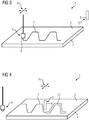
- Fig. 3 shows a third embodiment of a corresponding arrangement 1, in which the carrier component 2 with the carrier surface 3 is again fixed in position and the nozzle arrangement 4, as shown by the double arrows P1, is horizontally movable in every direction relative to the carrier surface 3. This means that any direction can be approached.
- a first method step the slip 7 is again released in the form of a narrow slip track via the nozzle arrangement 4, here for example in the form of a meandering structure.
- the heating means 5, here again a laser 6, is at rest during the release of the slip, that is to say that, unlike in the exemplary embodiments described above, in this variant the slip 7 is first completely applied.
- Fig. 4 shows quasi the second method step after the slip 7 has been applied via the nozzle arrangement 4.
- the heating means 5, that is to say the laser 6, is now moved on exactly the same line of movement as the nozzle arrangement 4 previously, as shown by the double arrows P4. This means that the laser 6 scans the slip layer and foams up to form the metal foam layer 10, such as Fig. 4 clearly shows.
- FIG. Fig. 5 As already described in the introduction, there is a finished component 11, as exemplified in FIG Fig. 5 is shown, from a plurality of individual layers 12 of metal foam, which were successively applied to one another or formed. It can be seen in Fig. 5 indicated, possible to produce virtually any, even filigree, structures.
- the component produced has overall box-shaped outer walls 13, between which inclined walls 14 are formed, that is, a stiffening internal structure, these walls 14 being shown only by way of example.
- Any other internal structures can be produced, for example also in the form of narrower webs or the like, precisely by applying the slip 7 accordingly and forming the metal foam layers 10 in layers 12 on top of one another, these layers 12 also being able to be applied and produced slightly offset in order to to produce oblique structures.
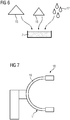
- Fig. 6 shows a basic diagram for the production of the slip 7.
- Starting materials are a metal powder 15, for example aluminum powder, a propellant 16, for example a metal hydride in the form of titanium dihydride, and a solvent 17, for example based on alcohol or acetone.
- the substances are mixed in order to make a slip 7 which is processed via the nozzle arrangement 4. It is drawn over the nozzle arrangement 4 in accordance with the nozzle width in the form of a more or less wide track, the nozzle width ultimately being able to vary as desired.
- Fig. 7 finally shows a medical examination or treatment device 18 in the form of an X-ray device comprising a component 11 here in the form of a C-arm 19, which therefore consists of a metal foam structure produced in the method according to the invention.
Landscapes
- Engineering & Computer Science (AREA)
- Manufacturing & Machinery (AREA)
- Chemical & Material Sciences (AREA)
- Materials Engineering (AREA)
- Mechanical Engineering (AREA)
- Powder Metallurgy (AREA)
Priority Applications (1)
| Application Number | Priority Date | Filing Date | Title |
|---|---|---|---|
| EP18211714.3A EP3666421A1 (fr) | 2018-12-11 | 2018-12-11 | Procédé de fabrication d'un composant tridimensionnel à partir d'une mousse métallique |
Applications Claiming Priority (1)
| Application Number | Priority Date | Filing Date | Title |
|---|---|---|---|
| EP18211714.3A EP3666421A1 (fr) | 2018-12-11 | 2018-12-11 | Procédé de fabrication d'un composant tridimensionnel à partir d'une mousse métallique |
Publications (2)
| Publication Number | Publication Date |
|---|---|
| EP3666421A1 EP3666421A1 (fr) | 2020-06-17 |
| EP3666421A9 true EP3666421A9 (fr) | 2020-12-02 |
Family
ID=64664910
Family Applications (1)
| Application Number | Title | Priority Date | Filing Date |
|---|---|---|---|
| EP18211714.3A Ceased EP3666421A1 (fr) | 2018-12-11 | 2018-12-11 | Procédé de fabrication d'un composant tridimensionnel à partir d'une mousse métallique |
Country Status (1)
| Country | Link |
|---|---|
| EP (1) | EP3666421A1 (fr) |
Families Citing this family (1)
| Publication number | Priority date | Publication date | Assignee | Title |
|---|---|---|---|---|
| CN113649569A (zh) * | 2021-08-23 | 2021-11-16 | 昆山晶微新材料研究院有限公司 | 一种多孔金属材料的制备方法和装置 |
Family Cites Families (6)
| Publication number | Priority date | Publication date | Assignee | Title |
|---|---|---|---|---|
| JPH0956708A (ja) * | 1995-08-23 | 1997-03-04 | Toshiba Corp | X線診断装置 |
| DE19928997C2 (de) * | 1999-06-24 | 2001-05-17 | Fraunhofer Ges Forschung | Verfahren und Vorrichtung zum Schäumen von Metallen |
| US20090047439A1 (en) * | 2007-08-16 | 2009-02-19 | Withers James C | Method and apparatus for manufacturing porous articles |
| KR20180008681A (ko) * | 2015-05-18 | 2018-01-24 | 프레지던트 앤드 펠로우즈 오브 하바드 칼리지 | 발포 잉크 조성물 및 3d 프린팅된 계층적 다공성 구조물 |
| KR101883272B1 (ko) * | 2016-10-31 | 2018-07-31 | 한국생산기술연구원 | 발포금속 제조방법 |
| CN107262718A (zh) * | 2017-07-07 | 2017-10-20 | 哈尔滨工程大学 | 一种利用激光熔覆成形工艺制备泡沫铝的方法 |
-
2018
- 2018-12-11 EP EP18211714.3A patent/EP3666421A1/fr not_active Ceased
Also Published As
| Publication number | Publication date |
|---|---|
| EP3666421A1 (fr) | 2020-06-17 |
Similar Documents
| Publication | Publication Date | Title |
|---|---|---|
| EP2794152B1 (fr) | Procédé de fabrication d'un composant compact et composant produit au moyen dudit procédé | |
| EP3074208B1 (fr) | Procédé d'impression 3d à barbotine | |
| EP2386405B1 (fr) | Dispositif de fabrication générative d'un objet tridimensionnel avec une délimitation du champ de construction | |
| DE3917277C2 (de) | Verfahren und Vorrichtung zur Herstellung von Fertigteilen als Verbundkörper aus pulverförmigen Werkstoffen | |
| EP2915611B1 (fr) | Dispositif et procédé de fabrication générative d'un composant | |
| EP2502730A1 (fr) | Dispositif et procédé destinés à la fabrication d'un composant structuré en couches | |
| EP2291260A1 (fr) | Procédé de fabrication d'un composant par fusion laser sélective et chambre de traitement adaptée à cet effet | |
| DE102007059865A1 (de) | Verfahren zur Herstellung eines Formkörpers durch schichtweises Aufbauen aus pulverförmigem, metallischen Werkstoff | |
| EP1400339A1 (fr) | Procédé pour la fabrication d'un article tridimensionnel | |
| EP3248719B1 (fr) | Procédé et dispositif de fabrication additive d'au moins une partie d'un composant | |
| WO2012062253A2 (fr) | Dispositif pour produire, réparer et/ou remplacer une pièce structurale à l'aide d'une poudre durcissable sous l'action d'un rayonnement énergétique, ainsi qu'un procédé et une pièce structurale produite selon ce procédé | |
| EP3381593B1 (fr) | Procédé de fusion ou de frittage sélectifs par faisceau | |
| EP4021703B1 (fr) | Installation de sérigraphie 3d et procédé de sérigraphie 3d pour la production d'un objet | |
| EP3666421A1 (fr) | Procédé de fabrication d'un composant tridimensionnel à partir d'une mousse métallique | |
| DE102014221423A1 (de) | Verfahren zur Herstellung großer Warmumformwerkzeuge mittels eines generativen Fertigungsverfahrens | |
| DE19928997A1 (de) | Verfahren und Vorrichtung zum Schäumen von Metallen | |
| DE10065594C2 (de) | Verfahren zum Herstellen von 3-dimensionalen Sinter Werkstücken | |
| DE102019131423A1 (de) | Additives Fertigungsverfahren | |
| EP3854570B1 (fr) | Procédé de fabrication d'une pièce moulée tridimensionnelle | |
| DE1301017B (de) | Verfahren zum Verhindern des Werfens bei der pulvermetallurgischen Herstellung von schlanken Formkoerpern | |
| AT525599B1 (de) | Verfahren zur Herstellung eines Bauteils aus einem Metallpulver und/oder Keramikpulver | |
| DE102010035506A9 (de) | Verfahren zur Herstellung eines Bauteils | |
| DE2211449A1 (de) | Verfahren zum herstellen langgestreckter koerper aus pulverfoermigen substanzen und zur durchfuehrung des verfahrens geeignete vorrichtung | |
| DE3928436C1 (fr) | ||
| DE102020129971A1 (de) | 3D-Druck - Kühlstrukturen |
Legal Events
| Date | Code | Title | Description |
|---|---|---|---|
| PUAI | Public reference made under article 153(3) epc to a published international application that has entered the european phase |
Free format text: ORIGINAL CODE: 0009012 |
|
| 17P | Request for examination filed |
Effective date: 20191018 |
|
| AK | Designated contracting states |
Kind code of ref document: A1 Designated state(s): AL AT BE BG CH CY CZ DE DK EE ES FI FR GB GR HR HU IE IS IT LI LT LU LV MC MK MT NL NO PL PT RO RS SE SI SK SM TR |
|
| AX | Request for extension of the european patent |
Extension state: BA ME |
|
| STAA | Information on the status of an ep patent application or granted ep patent |
Free format text: STATUS: THE APPLICATION HAS BEEN REFUSED |
|
| 18R | Application refused |
Effective date: 20210202 |