EP3666537B1 - Drucker und druckeranzeigevorrichtung - Google Patents
Drucker und druckeranzeigevorrichtung Download PDFInfo
- Publication number
- EP3666537B1 EP3666537B1 EP19215205.6A EP19215205A EP3666537B1 EP 3666537 B1 EP3666537 B1 EP 3666537B1 EP 19215205 A EP19215205 A EP 19215205A EP 3666537 B1 EP3666537 B1 EP 3666537B1
- Authority
- EP
- European Patent Office
- Prior art keywords
- printer
- display
- main body
- groove
- display device
- Prior art date
- Legal status (The legal status is an assumption and is not a legal conclusion. Google has not performed a legal analysis and makes no representation as to the accuracy of the status listed.)
- Active
Links
Images


Classifications
-
- B—PERFORMING OPERATIONS; TRANSPORTING
- B41—PRINTING; LINING MACHINES; TYPEWRITERS; STAMPS
- B41J—TYPEWRITERS; SELECTIVE PRINTING MECHANISMS, i.e. MECHANISMS PRINTING OTHERWISE THAN FROM A FORME; CORRECTION OF TYPOGRAPHICAL ERRORS
- B41J3/00—Typewriters or selective printing or marking mechanisms characterised by the purpose for which they are constructed
- B41J3/44—Typewriters or selective printing mechanisms having dual functions or combined with, or coupled to, apparatus performing other functions
- B41J3/46—Printing mechanisms combined with apparatus providing a visual indication
-
- B—PERFORMING OPERATIONS; TRANSPORTING
- B41—PRINTING; LINING MACHINES; TYPEWRITERS; STAMPS
- B41J—TYPEWRITERS; SELECTIVE PRINTING MECHANISMS, i.e. MECHANISMS PRINTING OTHERWISE THAN FROM A FORME; CORRECTION OF TYPOGRAPHICAL ERRORS
- B41J15/00—Devices or arrangements of selective printing mechanisms, e.g. ink-jet printers or thermal printers, specially adapted for supporting or handling copy material in continuous form, e.g. webs
- B41J15/04—Supporting, feeding, or guiding devices; Mountings for web rolls or spindles
- B41J15/042—Supporting, feeding, or guiding devices; Mountings for web rolls or spindles for loading rolled-up continuous copy material into printers, e.g. for replacing a used-up paper roll; Point-of-sale printers with openable casings allowing access to the rolled-up continuous copy material
-
- B—PERFORMING OPERATIONS; TRANSPORTING
- B41—PRINTING; LINING MACHINES; TYPEWRITERS; STAMPS
- B41J—TYPEWRITERS; SELECTIVE PRINTING MECHANISMS, i.e. MECHANISMS PRINTING OTHERWISE THAN FROM A FORME; CORRECTION OF TYPOGRAPHICAL ERRORS
- B41J29/00—Details of, or accessories for, typewriters or selective printing mechanisms not otherwise provided for
- B41J29/02—Framework
-
- B—PERFORMING OPERATIONS; TRANSPORTING
- B41—PRINTING; LINING MACHINES; TYPEWRITERS; STAMPS
- B41J—TYPEWRITERS; SELECTIVE PRINTING MECHANISMS, i.e. MECHANISMS PRINTING OTHERWISE THAN FROM A FORME; CORRECTION OF TYPOGRAPHICAL ERRORS
- B41J29/00—Details of, or accessories for, typewriters or selective printing mechanisms not otherwise provided for
- B41J29/12—Guards, shields or dust excluders
- B41J29/13—Cases or covers
-
- B—PERFORMING OPERATIONS; TRANSPORTING
- B41—PRINTING; LINING MACHINES; TYPEWRITERS; STAMPS
- B41J—TYPEWRITERS; SELECTIVE PRINTING MECHANISMS, i.e. MECHANISMS PRINTING OTHERWISE THAN FROM A FORME; CORRECTION OF TYPOGRAPHICAL ERRORS
- B41J3/00—Typewriters or selective printing or marking mechanisms characterised by the purpose for which they are constructed
- B41J3/36—Typewriters or selective printing or marking mechanisms characterised by the purpose for which they are constructed for portability, i.e. hand-held printers or laptop printers
-
- G—PHYSICS
- G07—CHECKING-DEVICES
- G07G—REGISTERING THE RECEIPT OF CASH, VALUABLES, OR TOKENS
- G07G5/00—Receipt-giving machines
-
- G—PHYSICS
- G09—EDUCATION; CRYPTOGRAPHY; DISPLAY; ADVERTISING; SEALS
- G09G—ARRANGEMENTS OR CIRCUITS FOR CONTROL OF INDICATING DEVICES USING STATIC MEANS TO PRESENT VARIABLE INFORMATION
- G09G5/00—Control arrangements or circuits for visual indicators common to cathode-ray tube indicators and other visual indicators
- G09G5/003—Details of a display terminal, the details relating to the control arrangement of the display terminal and to the interfaces thereto
Definitions
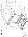
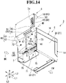
- the head unit 13 mainly includes a thermal head (printing head) (not shown), and is mounted in the casing 10. Specifically, the head unit 13 is mounted above the recording paper receiving portion 30 so as to be close to the front surface 24 of the casing 10.
- the thermal head is formed so as to extend in a width direction of the recording paper P, and is arranged at a position that is opposed to the platen roller 36 when the printer cover 11 is closed.
- the thermal head includes a plurality of heating elements linearly arrayed along the width direction of the recording paper P, and is biased to the platen roller 36 side. With this, the recording paper P can be held between the platen roller 36 and the head unit 13, and the thermal head can be appropriately pressed against the recording paper P fed by the platen roller 36, with the result that satisfactory printing can be performed.
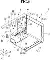
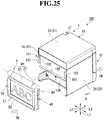
- the USB cable 7 is connected to the back surface 25 side of the casing 10 having the configuration described above so as to be pulled out downward from the first wall surface 75.
- the mode of connection is not limited thereto, and the USB cable 7 may be connected to the back surface 25 side of the casing 10 so as to be pulled out from the second wall surface 76.
- the hinge portion 60 has a rotation axis M1 that extends in parallel to each of the installation surface S and the back surface 25 of the casing 10, that is, along the right-and-left direction L3. With this, the display portion main body 50 is coupled to the fixing portion 40 so as to be rotated about the rotation axis M1 through intermediation of the hinge portion 60.
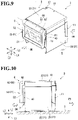
- the angle adjusting mechanism is provided in the hinge portion 60. Therefore, when the display portion main body 50 is set at a freely selected rotation angle by being rotated about the rotation axis M1, the display portion main body 50 can be maintained at that position.
- the specific rotation angle may be determined in consideration of, for example, the relationships between a diameter of the USB cable 7 and the opening sizes of the first groove portion 85 and the second groove portion 86, in addition to the relationship between the direction of the opening of the first groove portion 85 and the direction of the opening of the second groove portion 86 as described above.
- the rotation angle of the display portion main body 50 is an obtuse angle
- the USB cable 7 can be more easily mounted or removed as compared to the case in which the rotation angle is an acute angle. Therefore, of the rotation angle range of from 60° to 120°, the rotation angle range of from 90° to 120° is particularly preferred.
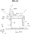
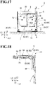
- the third cable groove 83 is formed so as to extend in the up-and-down direction on the back surface of the display case 52, and a lower end part of the third cable groove 83 communicates to the another groove end part 88 of the first cable groove 81.
- a groove width of the third cable groove 83 is set to such a size that the USB connector 7a can be received in the third cable groove 83.
- a female USB connector (not shown) to which the USB connector 7a of the USB cable 7 is connected is formed.
- the third cable groove 83 is formed so as to communicate to the connecting portion between the USB cable 7 and the display portion main body 50.
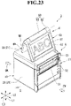
- the display portion main body 50 can be rotated by 180° from the first position P1. Therefore, the display portion 51 is likely to be visually recognized more clearly from the delivery slot 31 side, and visibility can be further enhanced.
- the customer can receive the ticket while visually recognizing the display portion 51.
Landscapes
- Physics & Mathematics (AREA)
- General Physics & Mathematics (AREA)
- Engineering & Computer Science (AREA)
- Computer Hardware Design (AREA)
- Theoretical Computer Science (AREA)
- Accessory Devices And Overall Control Thereof (AREA)
Claims (8)
- Druckeranzeigevorrichtung (6), die eingerichtet ist, an einer Außenfläche (21), die nicht eine Bodenfläche (22) eines Druckers (3) ist, befestigt zu werden und von dieser entfernbar zu sein, wobeidie Druckeranzeigevorrichtung (6) weiter eingerichtet ist, mindestens Daten aufzuweisen, die sich auf vorbestimmte Informationen beziehen, die durch ein Verbindungskabel (7), das zwischen einem Druckergehäuse (10) und der Druckeranzeigevorrichtung (6) verbunden ist, an sie übermittelt werden; und wobeidie Druckeranzeigevorrichtung (6) weiter eine Kabelrille (80) enthält, in der das Verbindungskabel (7) eingesetzt und aufgenommen werden kann.
- Drucker (3), umfassend:ein Druckergehäuse (10), das mehrere Außenflächen (21) enthält, die eine Bodenfläche (22) gegenüber einer Installationsfläche (S) enthalten, auf der der Drucker zu installieren ist, und einen Aufzeichnungspapieraufnahmeabschnitt (30) aufweist, der eingerichtet ist, Aufzeichnungspapier (P) durch einen Öffnungsabschnitt (20) aufzunehmen;eine Druckerabdeckung (11), die an das Druckergehäuse (10) gekoppelt und eingerichtet ist, den Öffnungsabschnitt (20) öffenbar abzudecken;die Druckeranzeigevorrichtung (6) nach Anspruch 1, die an der Außenfläche (21), die nicht die Bodenfläche (22) ist, befestigt und von dieser entfernbar ist und eingerichtet ist, die vorbestimmten Informationen anzuzeigen; undein Verbindungskabel (7), das zwischen dem Druckergehäuse (10) und der Druckeranzeigevorrichtung (6) verbunden ist und eingerichtet ist, mindestens die Daten, die sich auf die vorbestimmten Informationen beziehen, zu übermitteln,wobei das Verbindungskabel (7) in der Kabelrille (80) eingesetzt und aufgenommen ist.
- Drucker (3) nach Anspruch 2,wobei das Druckergehäuse (10) als die mehreren Außenflächen (21) mindestens eine Vorderfläche (24) und eine Rückfläche (25) enthält, die einander gegenüberliegen,wobei die Druckerabdeckung (11) an der Vorderfläche (24) bereitgestellt ist, undwobei die Druckeranzeigevorrichtung (6) trennbar an der Rückfläche (25) montiert ist.
- Drucker (3) nach Anspruch 2 oder Anspruch 3,wobei die Druckeranzeigevorrichtung (6) enthält:einen Befestigungsabschnitt (40), der trennbar an der Außenfläche (21) montiert ist;einen Anzeigeabschnittshauptkörper (50), der einen Anzeigeabschnitt (51) aufweist, der eingerichtet ist, die darauf bereitgestellten, vorbestimmten Informationen anzuzeigen, und mit dem das Verbindungskabel (7) verbunden ist;einen Scharnierabschnitt (60), der eine Drehachse (M1) aufweist und eingerichtet ist, den Befestigungsabschnitt (40) und den Anzeigeabschnittshauptkörper (50) aneinander zu koppeln, sodass der Anzeigeabschnittshauptkörper (50) in Bezug auf den Befestigungsabschnitt (40) um die Drehachse (M1) gedreht wird, undwobei die Kabelrille (80) enthält:eine erste Kabelrille (81), die in dem Scharnierabschnitt (60) gebildet ist, um sich entlang der Drehachse (M1) zu erstrecken;eine zweite Kabelrille (82), die in dem Befestigungsabschnitt (40) gebildet ist und mit einem Rillenendteil (87) der ersten Kabelrille (81) entlang einer Richtung der Drehachse (M1) in Verbindung steht; undeine dritte Kabelrille (80), die in dem Anzeigeabschnittshauptkörper (50) gebildet ist und mit einem anderen Rillenendteil (88) der ersten Kabelrille (81) entlang der Richtung der Drehachse (M1) in Verbindung steht und mit einem Verbindungsabschnitt zwischen dem Verbindungskabel (7) und dem Anzeigeabschnittshauptkörper (50) in Verbindung steht.
- Drucker (3) nach Anspruch 4,wobei der Scharnierabschnitt (60) enthält:einen ersten Scharnierabschnitt (61), der einstückig mit dem Befestigungsabschnitt (40) gebildet ist; undeinen zweiten Scharnierabschnitt (62), der einstückig mit dem Anzeigeabschnittshauptkörper (50) gebildet ist und so angeordnet ist, das er neben dem ersten Scharnierabschnitt (61) in der Richtung der Drehachse (M1) liegt, und an den ersten Scharnierabschnitt (61) gekoppelt ist, um so relativ um die Drehachse (M1) gedreht zu werden, undwobei die erste Kabelrille (81) enthält:einen ersten Rillenabschnitt (85), der in dem ersten Scharnierabschnitt (61) gebildet ist und mit der zweiten Kabelrille (82) in Verbindung steht; undeinen zweiten Rillenabschnitt (86), der in dem zweiten Scharnierabschnitt (62) gebildet ist und an die dritte Kabelrille (80) gekoppelt ist und eine Öffnung aufweist, die in Verbindung mit Drehung des zweiten Scharnierabschnitt (62) ihre Richtung ändert, undwobei die Öffnung des zweiten Rillenabschnitts (86) in dieselbe Richtung wie eine Richtung einer Öffnung des ersten Rillenabschnitts (85) gerichtet ist, wenn der Anzeigeabschnittshauptkörper (50) in einem vorbestimmten spezifischen Drehwinkel um die Drehachse (M1) in Bezug auf den Befestigungsabschnitt (40) gedreht wird.
- Drucker (3) nach Anspruch 4 oder Anspruch 5, wobei sich die Drehachse (M1) parallel zu jeder der Installationsfläche (S) und der Außenfläche (21) erstreckt, an der die Druckeranzeigevorrichtung (6) montiert ist.
- Drucker (3) nach einem der Ansprüche 4 bis 6,wobei das Druckergehäuse (10) weiter, als die mehreren Außenflächen (21) eine Deckfläche (23) gegenüber der Bodenfläche (22) enthält, undwobei der Anzeigeabschnittshauptkörper (50) eingerichtet ist, durch Drehung um die Drehachse (M1) zwischen einer ersten Position (P1), an der der Anzeigeabschnittshauptkörper (50) mit dem Befestigungsabschnitt (40) überlappt, und einer zweiten Position (P2), an der der Anzeigeabschnitt (51) über der Deckfläche (23) positioniert ist, verschoben zu werden.
- Drucker (3) nach Anspruch 7,wobei der Anzeigeabschnittshauptkörper (50) eingerichtet ist, innerhalb eines Drehwinkelbereichs von 180° um die Drehachse (M1) von der ersten Position (P1) gedreht zu werden, undwobei die zweite Position (P2) als eine Position eingerichtet ist, an der der Anzeigeabschnittshauptkörper (50) um 135° oder mehr um die Drehachse (M1) von der ersten Position (P1) gedreht ist.
Applications Claiming Priority (1)
| Application Number | Priority Date | Filing Date | Title |
|---|---|---|---|
| JP2018231685A JP7166161B2 (ja) | 2018-12-11 | 2018-12-11 | プリンタ及びプリンタ用表示装置 |
Publications (2)
| Publication Number | Publication Date |
|---|---|
| EP3666537A1 EP3666537A1 (de) | 2020-06-17 |
| EP3666537B1 true EP3666537B1 (de) | 2022-10-12 |
Family
ID=69147381
Family Applications (1)
| Application Number | Title | Priority Date | Filing Date |
|---|---|---|---|
| EP19215205.6A Active EP3666537B1 (de) | 2018-12-11 | 2019-12-11 | Drucker und druckeranzeigevorrichtung |
Country Status (3)
| Country | Link |
|---|---|
| US (1) | US10967651B2 (de) |
| EP (1) | EP3666537B1 (de) |
| JP (1) | JP7166161B2 (de) |
Families Citing this family (6)
| Publication number | Priority date | Publication date | Assignee | Title |
|---|---|---|---|---|
| JP7174613B2 (ja) * | 2018-12-11 | 2022-11-17 | セイコーインスツル株式会社 | プリンタ及びプリンタ用表示装置 |
| JP2021035738A (ja) * | 2019-08-30 | 2021-03-04 | セイコーエプソン株式会社 | 液体吐出装置 |
| JP7468195B2 (ja) * | 2020-06-30 | 2024-04-16 | セイコーエプソン株式会社 | 印刷装置 |
| JP7510388B2 (ja) * | 2021-07-08 | 2024-07-03 | セイコーエプソン株式会社 | 印刷装置 |
| JP7290371B1 (ja) | 2022-06-03 | 2023-06-13 | オイテル株式会社 | 衛生用品提供用ディスペンサ |
| KR102605334B1 (ko) * | 2023-09-22 | 2023-11-23 | 하나시스 주식회사 | 프린터 탈착형 키오스크 장치 |
Family Cites Families (12)
| Publication number | Priority date | Publication date | Assignee | Title |
|---|---|---|---|---|
| DE4332561A1 (de) * | 1993-09-24 | 1995-03-30 | Esselte Meto Int Gmbh | Druckmaschine mit einem Bedienungspanel |
| JP2003305917A (ja) | 2002-04-12 | 2003-10-28 | Japan Racing Association | 印刷装置 |
| JP2004343305A (ja) | 2003-05-14 | 2004-12-02 | Seiko Epson Corp | スキャナ・操作パネル用スタンド及び画像読取処理装置 |
| JP4720467B2 (ja) | 2005-12-05 | 2011-07-13 | セイコーエプソン株式会社 | 記録装置 |
| JP2010025960A (ja) | 2008-07-15 | 2010-02-04 | Kyocera Mita Corp | 画像形成装置 |
| JP5333766B2 (ja) | 2009-08-21 | 2013-11-06 | セイコーエプソン株式会社 | 記録装置 |
| JP4834778B2 (ja) | 2010-04-26 | 2011-12-14 | シチズンホールディングス株式会社 | プリンタスタンド |
| JP2013107339A (ja) | 2011-11-22 | 2013-06-06 | Canon Inc | ロック解除機構およびプリンタ装置 |
| JP5696985B1 (ja) | 2014-02-10 | 2015-04-08 | 富士ゼロックス株式会社 | 回動支持機構 |
| JP6299648B2 (ja) | 2015-03-31 | 2018-03-28 | ブラザー工業株式会社 | 印刷装置 |
| JP6515721B2 (ja) | 2015-07-24 | 2019-05-22 | セイコーエプソン株式会社 | 記録装置 |
| JP2018077396A (ja) | 2016-11-10 | 2018-05-17 | 株式会社リコー | 画像形成装置 |
-
2018
- 2018-12-11 JP JP2018231685A patent/JP7166161B2/ja active Active
-
2019
- 2019-11-27 US US16/697,735 patent/US10967651B2/en active Active
- 2019-12-11 EP EP19215205.6A patent/EP3666537B1/de active Active
Also Published As
| Publication number | Publication date |
|---|---|
| EP3666537A1 (de) | 2020-06-17 |
| US10967651B2 (en) | 2021-04-06 |
| JP7166161B2 (ja) | 2022-11-07 |
| US20200180330A1 (en) | 2020-06-11 |
| JP2020093433A (ja) | 2020-06-18 |
Similar Documents
| Publication | Publication Date | Title |
|---|---|---|
| EP3666537B1 (de) | Drucker und druckeranzeigevorrichtung | |
| US7017803B2 (en) | Point-of-sale terminal | |
| EP3666536B1 (de) | Drucker | |
| EP3495152B1 (de) | Drucker | |
| US20130235420A1 (en) | Data display device | |
| US7646941B2 (en) | Data capture apparatus with handwritten data receiving component | |
| US20070282687A1 (en) | Method and apparatus for redeeming an economic incentive | |
| US6206593B1 (en) | Computer with attached printer | |
| JP3060391U (ja) | 商品料金請求システムのワークステーションのための周辺機器キット | |
| US12260139B2 (en) | Printing apparatus | |
| US8201726B2 (en) | Point-of-sale printer system | |
| US20110102590A1 (en) | Self-service device comprising a surveillance unit | |
| JP6226815B2 (ja) | 商品販売データ処理装置、情報端末及び制御プログラム | |
| US20080123131A1 (en) | Operation Panel Structure | |
| CN115723442A (zh) | 印刷装置 | |
| CN115732951A (zh) | 电子设备 | |
| CN115734477A (zh) | 电子设备 | |
| CN115723441A (zh) | 印刷装置 | |
| JP2019188628A (ja) | 伝票発行装置、及びプログラム | |
| JP7711500B2 (ja) | 電子機器 | |
| CN216211344U (zh) | 一种两用自助取票机 | |
| JP2018032239A (ja) | 情報処理装置 | |
| JP2014146157A (ja) | 情報処理装置 | |
| JPH0573504A (ja) | 情報処理装置 |
Legal Events
| Date | Code | Title | Description |
|---|---|---|---|
| PUAI | Public reference made under article 153(3) epc to a published international application that has entered the european phase |
Free format text: ORIGINAL CODE: 0009012 |
|
| STAA | Information on the status of an ep patent application or granted ep patent |
Free format text: STATUS: THE APPLICATION HAS BEEN PUBLISHED |
|
| AK | Designated contracting states |
Kind code of ref document: A1 Designated state(s): AL AT BE BG CH CY CZ DE DK EE ES FI FR GB GR HR HU IE IS IT LI LT LU LV MC MK MT NL NO PL PT RO RS SE SI SK SM TR |
|
| AX | Request for extension of the european patent |
Extension state: BA ME |
|
| STAA | Information on the status of an ep patent application or granted ep patent |
Free format text: STATUS: REQUEST FOR EXAMINATION WAS MADE |
|
| 17P | Request for examination filed |
Effective date: 20201202 |
|
| RBV | Designated contracting states (corrected) |
Designated state(s): AL AT BE BG CH CY CZ DE DK EE ES FI FR GB GR HR HU IE IS IT LI LT LU LV MC MK MT NL NO PL PT RO RS SE SI SK SM TR |
|
| GRAP | Despatch of communication of intention to grant a patent |
Free format text: ORIGINAL CODE: EPIDOSNIGR1 |
|
| STAA | Information on the status of an ep patent application or granted ep patent |
Free format text: STATUS: GRANT OF PATENT IS INTENDED |
|
| INTG | Intention to grant announced |
Effective date: 20220609 |
|
| GRAS | Grant fee paid |
Free format text: ORIGINAL CODE: EPIDOSNIGR3 |
|
| GRAA | (expected) grant |
Free format text: ORIGINAL CODE: 0009210 |
|
| STAA | Information on the status of an ep patent application or granted ep patent |
Free format text: STATUS: THE PATENT HAS BEEN GRANTED |
|
| AK | Designated contracting states |
Kind code of ref document: B1 Designated state(s): AL AT BE BG CH CY CZ DE DK EE ES FI FR GB GR HR HU IE IS IT LI LT LU LV MC MK MT NL NO PL PT RO RS SE SI SK SM TR |
|
| REG | Reference to a national code |
Ref country code: GB Ref legal event code: FG4D |
|
| REG | Reference to a national code |
Ref country code: CH Ref legal event code: EP |
|
| REG | Reference to a national code |
Ref country code: DE Ref legal event code: R096 Ref document number: 602019020501 Country of ref document: DE |
|
| REG | Reference to a national code |
Ref country code: IE Ref legal event code: FG4D |
|
| REG | Reference to a national code |
Ref country code: AT Ref legal event code: REF Ref document number: 1523930 Country of ref document: AT Kind code of ref document: T Effective date: 20221115 |
|
| REG | Reference to a national code |
Ref country code: LT Ref legal event code: MG9D |
|
| REG | Reference to a national code |
Ref country code: NL Ref legal event code: MP Effective date: 20221012 |
|
| REG | Reference to a national code |
Ref country code: AT Ref legal event code: MK05 Ref document number: 1523930 Country of ref document: AT Kind code of ref document: T Effective date: 20221012 |
|
| PG25 | Lapsed in a contracting state [announced via postgrant information from national office to epo] |
Ref country code: NL Free format text: LAPSE BECAUSE OF FAILURE TO SUBMIT A TRANSLATION OF THE DESCRIPTION OR TO PAY THE FEE WITHIN THE PRESCRIBED TIME-LIMIT Effective date: 20221012 |
|
| PG25 | Lapsed in a contracting state [announced via postgrant information from national office to epo] |
Ref country code: SE Free format text: LAPSE BECAUSE OF FAILURE TO SUBMIT A TRANSLATION OF THE DESCRIPTION OR TO PAY THE FEE WITHIN THE PRESCRIBED TIME-LIMIT Effective date: 20221012 Ref country code: PT Free format text: LAPSE BECAUSE OF FAILURE TO SUBMIT A TRANSLATION OF THE DESCRIPTION OR TO PAY THE FEE WITHIN THE PRESCRIBED TIME-LIMIT Effective date: 20230213 Ref country code: NO Free format text: LAPSE BECAUSE OF FAILURE TO SUBMIT A TRANSLATION OF THE DESCRIPTION OR TO PAY THE FEE WITHIN THE PRESCRIBED TIME-LIMIT Effective date: 20230112 Ref country code: LT Free format text: LAPSE BECAUSE OF FAILURE TO SUBMIT A TRANSLATION OF THE DESCRIPTION OR TO PAY THE FEE WITHIN THE PRESCRIBED TIME-LIMIT Effective date: 20221012 Ref country code: FI Free format text: LAPSE BECAUSE OF FAILURE TO SUBMIT A TRANSLATION OF THE DESCRIPTION OR TO PAY THE FEE WITHIN THE PRESCRIBED TIME-LIMIT Effective date: 20221012 Ref country code: ES Free format text: LAPSE BECAUSE OF FAILURE TO SUBMIT A TRANSLATION OF THE DESCRIPTION OR TO PAY THE FEE WITHIN THE PRESCRIBED TIME-LIMIT Effective date: 20221012 Ref country code: AT Free format text: LAPSE BECAUSE OF FAILURE TO SUBMIT A TRANSLATION OF THE DESCRIPTION OR TO PAY THE FEE WITHIN THE PRESCRIBED TIME-LIMIT Effective date: 20221012 |
|
| PG25 | Lapsed in a contracting state [announced via postgrant information from national office to epo] |
Ref country code: RS Free format text: LAPSE BECAUSE OF FAILURE TO SUBMIT A TRANSLATION OF THE DESCRIPTION OR TO PAY THE FEE WITHIN THE PRESCRIBED TIME-LIMIT Effective date: 20221012 Ref country code: PL Free format text: LAPSE BECAUSE OF FAILURE TO SUBMIT A TRANSLATION OF THE DESCRIPTION OR TO PAY THE FEE WITHIN THE PRESCRIBED TIME-LIMIT Effective date: 20221012 Ref country code: LV Free format text: LAPSE BECAUSE OF FAILURE TO SUBMIT A TRANSLATION OF THE DESCRIPTION OR TO PAY THE FEE WITHIN THE PRESCRIBED TIME-LIMIT Effective date: 20221012 Ref country code: IS Free format text: LAPSE BECAUSE OF FAILURE TO SUBMIT A TRANSLATION OF THE DESCRIPTION OR TO PAY THE FEE WITHIN THE PRESCRIBED TIME-LIMIT Effective date: 20230212 Ref country code: HR Free format text: LAPSE BECAUSE OF FAILURE TO SUBMIT A TRANSLATION OF THE DESCRIPTION OR TO PAY THE FEE WITHIN THE PRESCRIBED TIME-LIMIT Effective date: 20221012 Ref country code: GR Free format text: LAPSE BECAUSE OF FAILURE TO SUBMIT A TRANSLATION OF THE DESCRIPTION OR TO PAY THE FEE WITHIN THE PRESCRIBED TIME-LIMIT Effective date: 20230113 |
|
| P01 | Opt-out of the competence of the unified patent court (upc) registered |
Effective date: 20230509 |
|
| REG | Reference to a national code |
Ref country code: DE Ref legal event code: R097 Ref document number: 602019020501 Country of ref document: DE |
|
| PG25 | Lapsed in a contracting state [announced via postgrant information from national office to epo] |
Ref country code: SM Free format text: LAPSE BECAUSE OF FAILURE TO SUBMIT A TRANSLATION OF THE DESCRIPTION OR TO PAY THE FEE WITHIN THE PRESCRIBED TIME-LIMIT Effective date: 20221012 Ref country code: RO Free format text: LAPSE BECAUSE OF FAILURE TO SUBMIT A TRANSLATION OF THE DESCRIPTION OR TO PAY THE FEE WITHIN THE PRESCRIBED TIME-LIMIT Effective date: 20221012 Ref country code: EE Free format text: LAPSE BECAUSE OF FAILURE TO SUBMIT A TRANSLATION OF THE DESCRIPTION OR TO PAY THE FEE WITHIN THE PRESCRIBED TIME-LIMIT Effective date: 20221012 Ref country code: DK Free format text: LAPSE BECAUSE OF FAILURE TO SUBMIT A TRANSLATION OF THE DESCRIPTION OR TO PAY THE FEE WITHIN THE PRESCRIBED TIME-LIMIT Effective date: 20221012 Ref country code: CZ Free format text: LAPSE BECAUSE OF FAILURE TO SUBMIT A TRANSLATION OF THE DESCRIPTION OR TO PAY THE FEE WITHIN THE PRESCRIBED TIME-LIMIT Effective date: 20221012 |
|
| REG | Reference to a national code |
Ref country code: CH Ref legal event code: PL |
|
| PLBE | No opposition filed within time limit |
Free format text: ORIGINAL CODE: 0009261 |
|
| STAA | Information on the status of an ep patent application or granted ep patent |
Free format text: STATUS: NO OPPOSITION FILED WITHIN TIME LIMIT |
|
| REG | Reference to a national code |
Ref country code: BE Ref legal event code: MM Effective date: 20221231 |
|
| PG25 | Lapsed in a contracting state [announced via postgrant information from national office to epo] |
Ref country code: SK Free format text: LAPSE BECAUSE OF FAILURE TO SUBMIT A TRANSLATION OF THE DESCRIPTION OR TO PAY THE FEE WITHIN THE PRESCRIBED TIME-LIMIT Effective date: 20221012 Ref country code: LU Free format text: LAPSE BECAUSE OF NON-PAYMENT OF DUE FEES Effective date: 20221211 Ref country code: AL Free format text: LAPSE BECAUSE OF FAILURE TO SUBMIT A TRANSLATION OF THE DESCRIPTION OR TO PAY THE FEE WITHIN THE PRESCRIBED TIME-LIMIT Effective date: 20221012 |
|
| 26N | No opposition filed |
Effective date: 20230713 |
|
| PG25 | Lapsed in a contracting state [announced via postgrant information from national office to epo] |
Ref country code: LI Free format text: LAPSE BECAUSE OF NON-PAYMENT OF DUE FEES Effective date: 20221231 Ref country code: IE Free format text: LAPSE BECAUSE OF NON-PAYMENT OF DUE FEES Effective date: 20221211 Ref country code: CH Free format text: LAPSE BECAUSE OF NON-PAYMENT OF DUE FEES Effective date: 20221231 |
|
| PG25 | Lapsed in a contracting state [announced via postgrant information from national office to epo] |
Ref country code: SI Free format text: LAPSE BECAUSE OF FAILURE TO SUBMIT A TRANSLATION OF THE DESCRIPTION OR TO PAY THE FEE WITHIN THE PRESCRIBED TIME-LIMIT Effective date: 20221012 Ref country code: FR Free format text: LAPSE BECAUSE OF NON-PAYMENT OF DUE FEES Effective date: 20221212 Ref country code: BE Free format text: LAPSE BECAUSE OF NON-PAYMENT OF DUE FEES Effective date: 20221231 |
|
| PG25 | Lapsed in a contracting state [announced via postgrant information from national office to epo] |
Ref country code: HU Free format text: LAPSE BECAUSE OF FAILURE TO SUBMIT A TRANSLATION OF THE DESCRIPTION OR TO PAY THE FEE WITHIN THE PRESCRIBED TIME-LIMIT; INVALID AB INITIO Effective date: 20191211 |
|
| PG25 | Lapsed in a contracting state [announced via postgrant information from national office to epo] |
Ref country code: CY Free format text: LAPSE BECAUSE OF FAILURE TO SUBMIT A TRANSLATION OF THE DESCRIPTION OR TO PAY THE FEE WITHIN THE PRESCRIBED TIME-LIMIT Effective date: 20221012 |
|
| PG25 | Lapsed in a contracting state [announced via postgrant information from national office to epo] |
Ref country code: MK Free format text: LAPSE BECAUSE OF FAILURE TO SUBMIT A TRANSLATION OF THE DESCRIPTION OR TO PAY THE FEE WITHIN THE PRESCRIBED TIME-LIMIT Effective date: 20221012 Ref country code: IT Free format text: LAPSE BECAUSE OF FAILURE TO SUBMIT A TRANSLATION OF THE DESCRIPTION OR TO PAY THE FEE WITHIN THE PRESCRIBED TIME-LIMIT Effective date: 20221012 |
|
| PG25 | Lapsed in a contracting state [announced via postgrant information from national office to epo] |
Ref country code: MC Free format text: LAPSE BECAUSE OF FAILURE TO SUBMIT A TRANSLATION OF THE DESCRIPTION OR TO PAY THE FEE WITHIN THE PRESCRIBED TIME-LIMIT Effective date: 20221012 |
|
| PG25 | Lapsed in a contracting state [announced via postgrant information from national office to epo] |
Ref country code: MC Free format text: LAPSE BECAUSE OF FAILURE TO SUBMIT A TRANSLATION OF THE DESCRIPTION OR TO PAY THE FEE WITHIN THE PRESCRIBED TIME-LIMIT Effective date: 20221012 |
|
| PG25 | Lapsed in a contracting state [announced via postgrant information from national office to epo] |
Ref country code: BG Free format text: LAPSE BECAUSE OF FAILURE TO SUBMIT A TRANSLATION OF THE DESCRIPTION OR TO PAY THE FEE WITHIN THE PRESCRIBED TIME-LIMIT Effective date: 20221012 |
|
| PG25 | Lapsed in a contracting state [announced via postgrant information from national office to epo] |
Ref country code: MT Free format text: LAPSE BECAUSE OF FAILURE TO SUBMIT A TRANSLATION OF THE DESCRIPTION OR TO PAY THE FEE WITHIN THE PRESCRIBED TIME-LIMIT Effective date: 20221012 |
|
| PG25 | Lapsed in a contracting state [announced via postgrant information from national office to epo] |
Ref country code: TR Free format text: LAPSE BECAUSE OF FAILURE TO SUBMIT A TRANSLATION OF THE DESCRIPTION OR TO PAY THE FEE WITHIN THE PRESCRIBED TIME-LIMIT Effective date: 20221012 |
|
| PGFP | Annual fee paid to national office [announced via postgrant information from national office to epo] |
Ref country code: DE Payment date: 20251028 Year of fee payment: 7 |
|
| PGFP | Annual fee paid to national office [announced via postgrant information from national office to epo] |
Ref country code: GB Payment date: 20251030 Year of fee payment: 7 |