EP3666606A1 - Schloss und schlüssel für lenksäulenverriegelung eines fahrzeugs - Google Patents
Schloss und schlüssel für lenksäulenverriegelung eines fahrzeugs Download PDFInfo
- Publication number
- EP3666606A1 EP3666606A1 EP19212973.2A EP19212973A EP3666606A1 EP 3666606 A1 EP3666606 A1 EP 3666606A1 EP 19212973 A EP19212973 A EP 19212973A EP 3666606 A1 EP3666606 A1 EP 3666606A1
- Authority
- EP
- European Patent Office
- Prior art keywords
- control cam
- key
- lock
- rotor
- key rod
- Prior art date
- Legal status (The legal status is an assumption and is not a legal conclusion. Google has not performed a legal analysis and makes no representation as to the accuracy of the status listed.)
- Withdrawn
Links
Images



Classifications
-
- B—PERFORMING OPERATIONS; TRANSPORTING
- B60—VEHICLES IN GENERAL
- B60R—VEHICLES, VEHICLE FITTINGS, OR VEHICLE PARTS, NOT OTHERWISE PROVIDED FOR
- B60R25/00—Fittings or systems for preventing or indicating unauthorised use or theft of vehicles
- B60R25/01—Fittings or systems for preventing or indicating unauthorised use or theft of vehicles operating on vehicle systems or fittings, e.g. on doors, seats or windscreens
- B60R25/02—Fittings or systems for preventing or indicating unauthorised use or theft of vehicles operating on vehicle systems or fittings, e.g. on doors, seats or windscreens operating on the steering mechanism
- B60R25/021—Fittings or systems for preventing or indicating unauthorised use or theft of vehicles operating on vehicle systems or fittings, e.g. on doors, seats or windscreens operating on the steering mechanism restraining movement of the steering column or steering wheel hub, e.g. restraining means controlled by ignition switch
- B60R25/0211—Fittings or systems for preventing or indicating unauthorised use or theft of vehicles operating on vehicle systems or fittings, e.g. on doors, seats or windscreens operating on the steering mechanism restraining movement of the steering column or steering wheel hub, e.g. restraining means controlled by ignition switch comprising a locking member radially and linearly moved towards the steering column
- B60R25/02115—Fittings or systems for preventing or indicating unauthorised use or theft of vehicles operating on vehicle systems or fittings, e.g. on doors, seats or windscreens operating on the steering mechanism restraining movement of the steering column or steering wheel hub, e.g. restraining means controlled by ignition switch comprising a locking member radially and linearly moved towards the steering column key actuated
- B60R25/02118—Fittings or systems for preventing or indicating unauthorised use or theft of vehicles operating on vehicle systems or fittings, e.g. on doors, seats or windscreens operating on the steering mechanism restraining movement of the steering column or steering wheel hub, e.g. restraining means controlled by ignition switch comprising a locking member radially and linearly moved towards the steering column key actuated with linear bolt motion parallel to the lock axis
- B60R25/02121—Fittings or systems for preventing or indicating unauthorised use or theft of vehicles operating on vehicle systems or fittings, e.g. on doors, seats or windscreens operating on the steering mechanism restraining movement of the steering column or steering wheel hub, e.g. restraining means controlled by ignition switch comprising a locking member radially and linearly moved towards the steering column key actuated with linear bolt motion parallel to the lock axis comprising safety devices avoiding locking until removal of the key
-
- B—PERFORMING OPERATIONS; TRANSPORTING
- B60—VEHICLES IN GENERAL
- B60R—VEHICLES, VEHICLE FITTINGS, OR VEHICLE PARTS, NOT OTHERWISE PROVIDED FOR
- B60R25/00—Fittings or systems for preventing or indicating unauthorised use or theft of vehicles
- B60R25/01—Fittings or systems for preventing or indicating unauthorised use or theft of vehicles operating on vehicle systems or fittings, e.g. on doors, seats or windscreens
- B60R25/02—Fittings or systems for preventing or indicating unauthorised use or theft of vehicles operating on vehicle systems or fittings, e.g. on doors, seats or windscreens operating on the steering mechanism
- B60R25/021—Fittings or systems for preventing or indicating unauthorised use or theft of vehicles operating on vehicle systems or fittings, e.g. on doors, seats or windscreens operating on the steering mechanism restraining movement of the steering column or steering wheel hub, e.g. restraining means controlled by ignition switch
- B60R25/0211—Fittings or systems for preventing or indicating unauthorised use or theft of vehicles operating on vehicle systems or fittings, e.g. on doors, seats or windscreens operating on the steering mechanism restraining movement of the steering column or steering wheel hub, e.g. restraining means controlled by ignition switch comprising a locking member radially and linearly moved towards the steering column
- B60R25/02115—Fittings or systems for preventing or indicating unauthorised use or theft of vehicles operating on vehicle systems or fittings, e.g. on doors, seats or windscreens operating on the steering mechanism restraining movement of the steering column or steering wheel hub, e.g. restraining means controlled by ignition switch comprising a locking member radially and linearly moved towards the steering column key actuated
- B60R25/02126—Fittings or systems for preventing or indicating unauthorised use or theft of vehicles operating on vehicle systems or fittings, e.g. on doors, seats or windscreens operating on the steering mechanism restraining movement of the steering column or steering wheel hub, e.g. restraining means controlled by ignition switch comprising a locking member radially and linearly moved towards the steering column key actuated with linear bolt motion perpendicular to the lock axis
- B60R25/02128—Fittings or systems for preventing or indicating unauthorised use or theft of vehicles operating on vehicle systems or fittings, e.g. on doors, seats or windscreens operating on the steering mechanism restraining movement of the steering column or steering wheel hub, e.g. restraining means controlled by ignition switch comprising a locking member radially and linearly moved towards the steering column key actuated with linear bolt motion perpendicular to the lock axis comprising safety devices avoiding locking until removal of the key
-
- E—FIXED CONSTRUCTIONS
- E05—LOCKS; KEYS; WINDOW OR DOOR FITTINGS; SAFES
- E05B—LOCKS; ACCESSORIES THEREFOR; HANDCUFFS
- E05B19/00—Keys; Accessories therefor
- E05B19/0017—Key profiles
- E05B19/0041—Key profiles characterized by the cross-section of the key blade in a plane perpendicular to the longitudinal axis of the key
- E05B19/0052—Rectangular flat keys
- E05B19/0058—Rectangular flat keys with key bits on at least one wide side surface of the key
Definitions
- the technical field of the invention is that of locks, in particular intended to be mounted in anti-theft devices of a motor vehicle steering column.
- the steering column anti-theft devices include a locking member or bolt for locking the steering column when the ignition key is removed.
- the bolt is mounted to move in the anti-theft device between a position for locking the column and a position for releasing the steering column.
- Such anti-theft devices generally comprise a lock with a stator and a rotor actuated by a coded key and controlling in particular the movement of the bolt during the rotation of the key in the lock or withdrawal of the latter from the lock.
- a conventional lock comprises a fixed body called a stator, mounted integral with the closing mechanism and / or the opening, a rotor, of generally cylindrical shape, fitted into the fixed body and having a housing that can accommodate a key.
- a set of flakes, radially movable, retains or frees the rotor in rotation relative to the fixed body. The flakes are moved when a key is inserted into the rotor housing, and the rotor is only released in rotation when the key is compliant. It is then the rotation of the rotor which triggers the unlocking of the closing mechanism.
- the cam path is arranged to receive at least one radial lug of the flakes of the latch so that the lugs follow the succession of peaks and valleys during the movement of the key rod in the rotor so that an axial displacement of the key causes a displacement of each of the flakes according to their sliding direction to the retracted position allowing the unlocking of the lock by a rotation of the key.
- the regulations require, when the key is inserted in the lock, that the bolt unlocks the steering column of a vehicle before starting the car accessories. It also requires the bolt to lock the vehicle's steering column when the ignition key is removed after the key has been turned to stop the vehicle engine.
- the bolt can be controlled by a control means such as a pull tab mounted in translation or a rotary mounted lever connected to a control cam itself integral with the lock rotor, the control cam having the function of detecting the presence or the absence of the key to retain the bolt associated with the control means.
- a control means such as a pull tab mounted in translation or a rotary mounted lever connected to a control cam itself integral with the lock rotor, the control cam having the function of detecting the presence or the absence of the key to retain the bolt associated with the control means.
- the lock therefore allows, via the bolt control means and the control cam, to unlock the bolt from the position where it rotates the steering column.
- control means exerts a force on the control cam to keep it in the retracted position, thus allowing the steering column to be locked.
- the presence of friction or even a bracing of the control cam can generate a blocking of the kinematics, preventing the control means from releasing the bolt and locking the steering column.
- the lock comprises a spring working in compression so as to push back a slide to block the steering column, when the key is not inserted.
- the key is passive because it is the spring of the control means which is active and which acts on the control means so as to move the control cam in the retracted position to release the bolt.
- the invention aims to solve these drawbacks by proposing a lock for an anti-theft device for a steering column of a motor vehicle and an associated key making it possible to avoid blocking of the control cam which is harmful to the kinematics of movement of the bolt in the the steering column.
- the invention relates to a lock for an anti-theft device for a steering column of a motor vehicle comprising a bolt and a means for holding the bolt in translation between a locking position of the steering column and a position for releasing the column.
- the lock comprises a rotor rotatably mounted about an axis A in a stator and a plurality of flakes slidably mounted in the rotor in a transverse direction B between at least one projecting position in which they immobilize the rotor relative to the stator, and a retracted position inside the rotor after the introduction into the rotor of a key rod, allowing the unlocking of the lock by a rotation of the key.
- the lock according to the invention comprises a control cam intended to follow at least the profile of a control cam path provided on the key rod during the movement of said key in the rotor, the control cam being able to move move in the rotor between: a projecting position obtained when the control cam follows the profile of the control cam path when the key rod is introduced, the control cam being able to actuate the holding means in order to keep the bolt in position release of the steering column, and a retracted position obtained when the control cam follows the profile of the control cam path when removing the key rod, corresponding to the position of release of the bolt to lock the steering column
- the control cam comprises at least one lug arranged to be received in the control cam path of the key rod so as to follow the profile of the key rod in the rotor so that a displacement axial of the key rod causes a displacement of the control cam.
- control cam is mounted in translation in the rotor allowing the control cam to slide in the transverse direction B.
- control cam is integral with a lever of the holding means.
- the control cam and the lever are mounted in rotation about an axis of rotation C on the rotor to move the bolt between a release position and a locking position.
- the control cam comprises a central orifice intended to be traversed by the key rod, the lug being positioned inside the central orifice and more precisely on an internal wall delimiting the central orifice.
- control cam is positioned between the flakes and an entry face of the lock through which the key is intended to be inserted, the control cam being positioned parallel to the flakes.
- the control cam comprises two lugs positioned on the internal wall of the central orifice including a first lug intended to move the control cam in the projecting position when the first lug follows the profile of the key stem control cam path and a second lug intended to move the control cam in the retracted position when the second lug follows the profile of a key stem retracting cam path.
- the pins are opposite and facing each other to cooperate with the control cam tracks which are opposite and offset from each other.
- the holding means comprises a spring for holding a first end of the lever in abutment against the control cam and bringing it back to the retracted position corresponding to the release position of the bolt (3) to block the steering column.
- the invention also relates to a key comprising a key rod arranged to cooperate with flakes of a lock of an anti-theft device as described above.
- the key rod has a quadrilateral section, elongated in the direction of sliding of the flakes, and two opposite lateral faces, at least one of which comprises a coding cam path comprising a succession of crests and valleys to form a coding.
- the coding cam path is arranged to receive at least one lug of the flakes of the lock so that the lugs follow this succession of crests and troughs when the key shank is introduced into the rotor so that an axial displacement of the key causes a displacement of each of the flakes according to the transverse direction B to the retracted position allowing the lock to be unlocked by rotating the key.
- the coding cam path is extended by the control cam path so that a lug provided on the control cam can follow the control cam path after following the coding cam path to bring the control cam in the projecting position when the key shank is inserted into the rotor.
- the control cam path is recessed and offset with respect to the coding cam path in the plane of the lateral faces and towards the bolt holding means.
- control cam path is rectilinear, and is positioned in a downstream region of the key rod relative to the direction of introduction of the key into the lock.
- the key rod comprises a first lateral flange forming the control cam path intended to guide a first lug positioned on an internal wall of a central orifice of the control cam.
- the first lateral flange is positioned in a downstream region of the key rod relative to the direction of introduction of the key into the lock.
- the key rod comprises a second lateral rim opposite the first lateral rim and forming a retracting control cam path for the control cam intended to guide a second lug positioned on the internal wall of the central orifice of the cam. ordered.
- the second lateral flange is positioned in an upstream region of the key rod relative to the direction of introduction of the key into the lock.
- the key rod comprises a first guide groove on a first lateral face positioned in the upstream zone and which extends the first lateral rim offset in the plane of the first lateral face.
- the key rod comprises a second guide groove positioned on the first lateral face extending the second lateral rim offset in the plane of the first lateral face.
- the guide grooves are opposite and partially offset from each other in the direction of the axis A.
- the first lug When the key is inserted into the lock, the first lug is guided by the first guide groove and then by the first lateral edge. In parallel, the second lug runs along the second lateral edge then slides along the second guide groove and vice versa when the key is withdrawn.
- the invention thus provides a lock and a key for an anti-theft device for a steering column of a motor vehicle and an associated key making it possible to avoid blocking of the control cam.
- the invention also relates to an assembly comprising a lock according to the invention and a key according to the invention.
- the anti-theft device 2 of a motor vehicle steering column comprises a lock 1 comprising a bolt 3 and a means 4 for holding the bolt 3 in translation between a locking position of the steering column and a position for releasing the column.
- the bolt 3 slides between a projecting position in which it locks the steering column and a retracted position in which it releases the steering column.
- the lock 1 comprises a rotor 5 rotatably mounted around an axis A in a stator 6 and a plurality of flakes 7 slidably mounted in the rotor 5 in a transverse direction B between at least one projecting position in which they immobilize in rotation the rotor 5 relative to the stator 6, and a retracted position inside the rotor 5 after the introduction into the rotor 5 of a key rod 8, allowing the rotation of the rotor 5.
- the latch 1 comprises a control cam 9 intended to follow at least the profile of a control cam path 10 provided on the key rod 8 when it is moved longitudinally in the rotor 5.
- the projecting position is obtained when the control cam 9 follows the rising profile of the control cam path 10 of the key rod 8, the rising profile of the control cam path of the key rod being defined in the direction of insertion of the key rod.
- the control cam 9 comprises at least one lug 11 arranged to be received in the control cam path 10 of the key rod 8 so as to follow the profile of the key rod 8 in the rotor 5 so that a axial displacement of the key rod 8 causes displacement of the control cam 9 in the transverse direction B.
- the lug 11 can have a parallelepiped shape and extend along the axis A.
- the control cam 9 comprises a central orifice 12 intended to be crossed by the key rod 8.
- the lug 11 is positioned inside the central orifice 12 and more precisely on an internal wall 15 delimiting the central orifice 12.
- the control cam 9 and the central orifice 12 have a generally parallelepiped shape.
- the control cam 9 has a general quadrilateral section, close to that of the flakes 7.
- the central orifice 12 has a quadrilateral section.
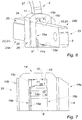
- the inner wall 15 comprises two opposite side walls 15a, 15b of greater length and two opposite transverse walls 15c, 15d of shorter length, as illustrated in the Figures 6 and 7 .
- the lug 11 is positioned on the side wall 15a intended to be opposite the control cam path 10 of the key rod 8.
- the control cam 9 is housed inside the lock 1 in the same housing provided for the flakes 7 and parallel to the flakes 7.
- the control cam 9 is aligned with the flakes 7.
- the control cam 9 comprises a contact surface 14 on its smaller external side which is intended to come into contact with the first end 30 of the lever 27.
- the contact surface 14 is curved.
- the control cam 9 comprises two lateral surfaces 14a, 14b on its larger external sides.
- control cam 9 is positioned upstream of the flakes 7, near an entry face 13 of the latch 1.
- This entry face 13 corresponds to the face by which the key is inserted.
- the upstream and downstream positions are defined relative to the direction of insertion of the key.
- the control cam 9 is positioned between the entry face 13 of the latch 1 and the flakes 7.
- control cam 9 can be positioned differently, such as for example downstream of the flakes 7.
- the holding means 4 comprises a lever 27 able to rotate about an axis of rotation 28 while being able to translate in the direction B under the impulse of the spring 29.
- the holding means 4 in fact comprises a spring 29 to hold a first end 30 of the lever 27 pressing against the control cam 9 and bringing it back to the retracted position corresponding to the bolt locking position 3.
- the spring 29 is supported on a support 32.
- the lever 27 comprises a second end 31 cooperating with the bolt 3 to maintain the latter in the bolt release position.
- the key intended to be introduced into the lock 1 comprises a key rod 8 arranged to cooperate with the flakes 7 of the lock 1 of the anti-theft device 2.
- the key rod 8 has a quadrilateral section, elongated in the direction of sliding of the flakes 7, and two opposite lateral faces 16a, 16b, at least one of which comprises a coding cam path 17 comprising a succession of crests 18 and hollow 19 to form a coding.
- the coding cam path 17 is arranged to receive at least one lug 20 of the flakes 7 of the latch 1 so that the lugs 20 follow this succession of ridges 18 and of ridges 19 during the introduction of the key rod 8 into the rotor 5 so that an axial displacement of the key causes a displacement of each of the flakes 7 in the transverse direction B until the projecting position in this case flush with the diameter of the rotor ( fig. 3 ) allowing the unlocking of the lock 1 by a rotation of the key. It should be noted that it is the rotation of the key which will bring the bolt 3 out of its locking position, thereby freeing the steering column.
- the key rod 8 comprises at least one control cam path 10 intended to slide the control cam 9 housed in the rotor 5 of the latch 1 when the key rod 8 moves in the rotor 5 according to the transverse direction B between the projecting position and the retracted position.
- the figures 2 and 3 illustrate an embodiment in which the coding cam path 17 is extended by the control cam path 10 so that the lug 11 provided on the control cam 9 can follow the control cam path 10 after following the coding cam path 17 for bringing the control cam 9 into the projecting or retracted position depending on the movement of the key rod 8 in the rotor 5.
- the control cam path 10 is offset with respect to the coding cam path 17 towards the holding means 4 of the bolt 3 and in the plane of a first lateral face 16a of the key rod 8.
- control cam path 10 is shifted towards the top of the figure 3 .
- the control cam path 10 is straight, for example.
- the control cam 9 is in the retracted position when the key is not inserted in the latch 1 or when the lug 11 of the control cam 9 follows the profile of the coding cam path 17 of the key rod 8 at start to insert the key into the lock.
- the key rod 8 comprises a first section 42 and a second section 43 opposite and parallel to each other.
- the control cam path 10 is positioned along the first edge 42 of the key rod 8 as close as possible to the first end 30 of the lever 27.
- the control cam track 10 is positioned in a downstream region 24b of the key rod 8 relative to the direction of introduction of the key into the lock 1, that is to say near the rear end 33 of the key rod 8 intended to receive a gripping element.
- the control cam path 10 is hollowed out or, in other words, hollowed out in the key rod 8.
- the lugs 20 of the glitter 7 and the lug 11 of the control cam 9 follow the coding cam path 17 of the key rod 8, as shown in the figure 2 , until the lug 11 of the control cam 9 is inserted into the control cam path 10 to follow its profile, as shown in the figure 3 , causing the sliding in the transverse direction B of the control cam 9 in the projecting position, causing the rotation and translation in the direction of the compression of the spring 29, of the lever 27 of the holding means 4 towards the direction E.
- the spring 29 is then compressed and the second end 31 of the lever 27 is capable of holding the bolt 3 in the position for releasing the steering column once this position has been reached following a rotation of the key.
- the key rod 8 may symmetrically comprise two control cam paths 10 arranged on each lateral face 16a, 16b of the key rod 8 and cooperating with two lugs 11 positioned in opposition on the internal wall 15 of the cam command 9.
- control cam path 10 cut into a hollow can be positioned in the upstream region 24a of the key rod 8 or open out through one of the sections 42, 43 forming an external control cam path .
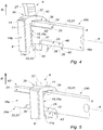
- the figures 4 to 10 show another embodiment in which the control cam 9 follows an external control cam path 10.
- the control cam 9 comprises two lugs 11, 11a positioned on an internal wall 15 of the central orifice 12 including a first lug 11 intended to move the control cam 9 in the projecting position when the first lug 11 follows the profile of the path control cam 10 of the key rod 8 and a second lug 11a intended to move the control cam 9 in the retracted position when the second lug 11a follows the profile of a retraction control cam path 23 provided on the rod key 8.
- the pins 11, 11a are opposite and facing one another to cooperate with the control cam tracks 10, 23 which are opposite and offset.
- They can have a parallelepiped shape and extend along the axis A.
- the control cam path 10 is then formed by the first lateral flange 21 of the key rod 8 formed on the first edge 42 and is intended to guide the first lug 11 of the control cam 9.
- the first lateral flange 21 is positioned in the downstream region 24b of the key rod 8 relative to the direction of introduction of the key into the latch 1.
- the second lateral flange 22 is positioned in an upstream region 24a of the key rod 8 relative to the direction of introduction of the key into the latch 1.
- the second lateral flange 22 extends to a front end 44 of the key.
- the key rod 8 comprises a first guide groove 25 hollowed out in its first lateral face 16a and positioned in the upstream zone 24a.
- the first guide groove 25 is offset relative to the first lateral edge 21, in a direction opposite to the holding means 4 of the bolt 3 and in the plane of the first lateral face 16a.
- the first guide groove 25 is hollowed out along and in a portion of the first edge 42 of the key rod 8.
- the first guide groove 25 has an elongated, rectilinear shape, is of substantially quadrilateral section and extends to a front end 44 of the key.
- a first step 34 is formed between the first guide groove 25 and the first lateral edge 21.
- the key rod 8 comprises a second guide groove 26 hollowed out in its first lateral face 16a, and extending the second lateral rim 22 in an offset manner.
- the second guide groove 26 is hollowed out along and in a portion of the second edge 43 of the key rod 8 opposite the first edge 42.
- a second step 35 is formed between the second guide groove 26 and the second lateral edge 22.
- the second guide groove 26 has an elongated, rectilinear shape, and is of substantially quadrilateral section.
- the guide grooves 25, 26 are opposite and partially offset with respect to each other in the direction of the axis A and in the plane of the lateral faces 16a, 16b.
- the first guide groove 25 and the second guide groove 26 are outside the key rod 8.
- the first guide groove 25 is delimited by a first wall 36 parallel to the first lateral face 16a of the key rod 8 and a second wall 37, parallel to the first lateral rim 21.
- the first wall 36 is perpendicular to the second wall 37 .
- the first step 34 is formed by a wall connecting the first side edge 21 to the second wall 37.
- the first step 34 is preferably substantially inclined relative to the second wall 37 and to the first side edge 21 with rounded portions at its ends to facilitate the sliding of the lug.
- the second guide groove 26 is delimited by a first wall 38 parallel to the first lateral face 16a of the key rod 8 and a second wall 39, parallel to the second lateral flange 22.
- the first wall 38 is perpendicular to the second wall 39 .
- the second step 35 is formed by a wall connecting the second lateral flange 22 to the second wall 39 of the second guide groove 26.
- the second step 35 is preferably substantially inclined relative to the second wall 39 and to the second lateral flange 22 with rounded portions at its ends to facilitate the sliding of the lug.
- the second guide groove 26 is also delimited by a downstream wall 46, opposite the second step 35.
- the first guide groove 25 and the second guide groove 26 partially overlap so as to present a respective portion 40, 41 facing each other.
- the first lug 11 of the control cam 9 is guided by the first guide groove 25 and, in parallel, the second lug 11a follows the second lateral edge 22.
- the control cam 9 thus remains in the retracted position in which the bolt 3 is in the locking position of the steering column.
- the first lug 11 of the control cam 9 slides, as the key is inserted, in the portion 40 of the first guide groove 25 which is opposite the second portion 41 of the second groove guide 26, to the first step 34.
- the first lateral edge 21 forming the control cam path 10 being offset in height relative to the first guide groove 25 in the plane of the first lateral face 16a, the control cam 9 moves from the retracted position to the position protruding, actuating the holding means 4 towards its bolt holding position 3 in the release position of the steering column.
- the second lug 11a then engages in the second guide groove 26 in order to slide along the latter until the key is fully inserted in the lock 1.
- the figure 7 shows a transverse view of the control cam 9 receiving the key.
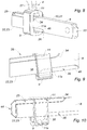
- the figures 8 to 10 represent different steps during the extraction of the key from the lock 1 according to this embodiment.
- the first lug 11 is found facing the first guide groove 25 without necessarily being in contact with it, at the level of the portions 40, 41.
- the second guide groove 26 being offset in height relative to the second lateral flange 22 forming the retracting control cam path 23, in the plane of the first lateral face 16a, the control cam 9 moves from the projecting position towards the retracted position, actuating the holding means 4 in its bolt release position 3 which will be able to enter its locking position of the steering column.
- the first lug 11 engages in the first guide groove 25 and then slides along the latter to the front end 44 of the key and the complete extraction of the key from the lock 1.
- first guide groove 25 can be positioned on the first lateral face 16a and the second guide groove 26 can be positioned on the second lateral face 16b of the key rod 8.
- the second side face 16b of the key rod 8 may also include another first guide groove 25 and another second guide groove 26 arranged in symmetry with those positioned on the first side face 16a.
- the control cam 9 may include a lateral guide groove 45 to improve its sliding in the housing of the lock 1.
- the figure 11 shows an anti-theft device for a motor vehicle steering column according to another embodiment of the invention.
- the control cam 9 is mounted in rotation on the rotor 5 around an axis of rotation C perpendicular to the axis of rotation A of the rotor 5.
- the holding means 4 of the anti-theft device 2 comprises a lever 27 mounted in rotation about the axis of rotation C.
- the control cam 9 is integral with or integrated into the lever 27 of the holding means 4 of the anti-theft device 2.
- the first end 30 of the lever 27 is fixed to the control cam 9.
- the second end 31 of the lever 27 is capable of holding the bolt 3 in its position for releasing the steering column.
- the control cam 9 comprises a lug 11 arranged to be received in the control cam path 10 of the key rod 8 so as to follow its profile during the introduction or withdrawal of the key rod 8 in the rotor 5 so that an axial displacement of the key rod 8 causes rotation of the control cam 9 in the plane of the figure 11 .
- the lug 11 of the control cam 9 also follows the control cam path 10 of the key rod 8, the lever 27 is furthermore rotated in one direction opposite to that of insertion, under the additional effect of a spring (not shown) which will maintain the retracted position.
Landscapes
- Engineering & Computer Science (AREA)
- Mechanical Engineering (AREA)
- Lock And Its Accessories (AREA)
Applications Claiming Priority (1)
| Application Number | Priority Date | Filing Date | Title |
|---|---|---|---|
| FR1872631A FR3089472B1 (fr) | 2018-12-10 | 2018-12-10 | Verrou et clé pour dispositif antivol de colonne de direction de véhicule automobile |
Publications (1)
| Publication Number | Publication Date |
|---|---|
| EP3666606A1 true EP3666606A1 (de) | 2020-06-17 |
Family
ID=66218237
Family Applications (1)
| Application Number | Title | Priority Date | Filing Date |
|---|---|---|---|
| EP19212973.2A Withdrawn EP3666606A1 (de) | 2018-12-10 | 2019-12-02 | Schloss und schlüssel für lenksäulenverriegelung eines fahrzeugs |
Country Status (2)
| Country | Link |
|---|---|
| EP (1) | EP3666606A1 (de) |
| FR (1) | FR3089472B1 (de) |
Citations (7)
| Publication number | Priority date | Publication date | Assignee | Title |
|---|---|---|---|---|
| FR2480213A1 (fr) * | 1980-04-15 | 1981-10-16 | Bakony Fem Elektromoskeszulek | Serrure de direction a contacteur d'allumage incorpore et verrouillage double pour vehicules automobiles |
| EP1772576A2 (de) * | 2005-10-05 | 2007-04-11 | Kabushiki Kaisha Tokai-Rika-Denki-Seisakusho | Schliesszylinder und Schlüssel |
| WO2008074726A1 (fr) | 2006-12-19 | 2008-06-26 | Valeo Securite Habitacle | Antivol de securite pour vehicule |
| WO2012019757A1 (de) * | 2010-08-10 | 2012-02-16 | Volkswagen Aktiengesellschaft | Schliessvorrichtung |
| EP2679453A1 (de) * | 2012-06-29 | 2014-01-01 | Huf Hülsbeck & Fürst GmbH & Co. KG | Mechanische Lenkverriegelung |
| WO2014096054A1 (fr) * | 2012-12-21 | 2014-06-26 | U-Shin France Sas | Actionneur de contact pour vehicule automobile |
| CN106917538A (zh) * | 2015-12-24 | 2017-07-04 | 黄伟敏 | 叶片锁头 |
-
2018
- 2018-12-10 FR FR1872631A patent/FR3089472B1/fr active Active
-
2019
- 2019-12-02 EP EP19212973.2A patent/EP3666606A1/de not_active Withdrawn
Patent Citations (7)
| Publication number | Priority date | Publication date | Assignee | Title |
|---|---|---|---|---|
| FR2480213A1 (fr) * | 1980-04-15 | 1981-10-16 | Bakony Fem Elektromoskeszulek | Serrure de direction a contacteur d'allumage incorpore et verrouillage double pour vehicules automobiles |
| EP1772576A2 (de) * | 2005-10-05 | 2007-04-11 | Kabushiki Kaisha Tokai-Rika-Denki-Seisakusho | Schliesszylinder und Schlüssel |
| WO2008074726A1 (fr) | 2006-12-19 | 2008-06-26 | Valeo Securite Habitacle | Antivol de securite pour vehicule |
| WO2012019757A1 (de) * | 2010-08-10 | 2012-02-16 | Volkswagen Aktiengesellschaft | Schliessvorrichtung |
| EP2679453A1 (de) * | 2012-06-29 | 2014-01-01 | Huf Hülsbeck & Fürst GmbH & Co. KG | Mechanische Lenkverriegelung |
| WO2014096054A1 (fr) * | 2012-12-21 | 2014-06-26 | U-Shin France Sas | Actionneur de contact pour vehicule automobile |
| CN106917538A (zh) * | 2015-12-24 | 2017-07-04 | 黄伟敏 | 叶片锁头 |
Also Published As
| Publication number | Publication date |
|---|---|
| FR3089472A1 (fr) | 2020-06-12 |
| FR3089472B1 (fr) | 2022-04-01 |
Similar Documents
| Publication | Publication Date | Title |
|---|---|---|
| EP2179115B1 (de) | Schlüssel zur betätigung eines schlosses mit verbesserter schlagfestigkeit | |
| EP1084915A1 (de) | Kraftfahrzeuglenkungsdiebstahlsicherung | |
| EP2121392B1 (de) | Diebstahlsicherung für fahrzeuge | |
| FR2521505A1 (fr) | Antivol pour vehicules a moteur | |
| EP3666606A1 (de) | Schloss und schlüssel für lenksäulenverriegelung eines fahrzeugs | |
| FR2600365A1 (fr) | Mecanisme pour systemes de serrure sans cle | |
| FR2943706A1 (fr) | Clef pour cylindre a pompes | |
| EP3041715B1 (de) | Diebstahlschutzvorrichtung für die lenksäule eines kraftfahrzeugs | |
| FR2638132A1 (fr) | Dispositif d'immobilisation en rotation et/ou en translation par rapport a un support d'un arbre guide dans au moins l'un de ces mouvements par rapport audit support et notamment d'un arbre de direction | |
| EP2104622B1 (de) | Diebstahlsicherungsvorrichtung für ein fahrzeug mit einem eine elastische nase aufweisenden schieber | |
| EP1953048A1 (de) | Vorrichtung zur Blockierung der Lenksäule eines Fahrzeugs | |
| EP1637415B2 (de) | Elektrische Vorrichtung für das Verriegeln/Entriegeln einer Lenksäule | |
| EP2635465B1 (de) | Diebstahlschutz für fahrzeuglenksäule mit sicherung durch eindrücken | |
| FR2716484A1 (fr) | Dispositif anti-effraction à délateur pour serrure de sûreté. | |
| EP2746115B1 (de) | Kontaktschütz für Fahrzeug | |
| FR2710307A1 (fr) | Anti-vol notamment pour moto à freinage à disques. | |
| EP2496447B1 (de) | Diebstahlschutzvorrichtung für eine lenksäule eines fahrzeuges mit einem antrieb für einen totgehenden riegel | |
| EP3498944A1 (de) | Schlüssel und zylinder für sicherheitsschloss | |
| EP3569799B1 (de) | Schliessbetätigungszusammenbau mit schlüssel | |
| EP0424288B1 (de) | Türverriegelung und Türrahmen mit solcher Verriegelung | |
| EP2746114B1 (de) | Kontaktschütz für Fahrzeug | |
| EP3233587B1 (de) | Diebstahlschutzvorrichtung für lenksäule | |
| FR2930578A1 (fr) | Mecanisme de gache | |
| EP0869236B1 (de) | Von einer Seite aus betätigbarer Sicherheitszylinder selbst wenn ein Schlüssel auf der anderen Seite eingesteckt ist | |
| FR2631907A1 (fr) | Antivol de blocage de direction des vehicules automobiles |
Legal Events
| Date | Code | Title | Description |
|---|---|---|---|
| PUAI | Public reference made under article 153(3) epc to a published international application that has entered the european phase |
Free format text: ORIGINAL CODE: 0009012 |
|
| STAA | Information on the status of an ep patent application or granted ep patent |
Free format text: STATUS: THE APPLICATION HAS BEEN PUBLISHED |
|
| AK | Designated contracting states |
Kind code of ref document: A1 Designated state(s): AL AT BE BG CH CY CZ DE DK EE ES FI FR GB GR HR HU IE IS IT LI LT LU LV MC MK MT NL NO PL PT RO RS SE SI SK SM TR |
|
| AX | Request for extension of the european patent |
Extension state: BA ME |
|
| STAA | Information on the status of an ep patent application or granted ep patent |
Free format text: STATUS: REQUEST FOR EXAMINATION WAS MADE |
|
| 17P | Request for examination filed |
Effective date: 20201110 |
|
| RBV | Designated contracting states (corrected) |
Designated state(s): AL AT BE BG CH CY CZ DE DK EE ES FI FR GB GR HR HU IE IS IT LI LT LU LV MC MK MT NL NO PL PT RO RS SE SI SK SM TR |
|
| RAP3 | Party data changed (applicant data changed or rights of an application transferred) |
Owner name: U-SHIN FRANCE |
|
| GRAP | Despatch of communication of intention to grant a patent |
Free format text: ORIGINAL CODE: EPIDOSNIGR1 |
|
| STAA | Information on the status of an ep patent application or granted ep patent |
Free format text: STATUS: GRANT OF PATENT IS INTENDED |
|
| INTG | Intention to grant announced |
Effective date: 20230404 |
|
| RAP3 | Party data changed (applicant data changed or rights of an application transferred) |
Owner name: MINEBEA ACCESSSOLUTIONS FRANCE |
|
| STAA | Information on the status of an ep patent application or granted ep patent |
Free format text: STATUS: THE APPLICATION IS DEEMED TO BE WITHDRAWN |
|
| 18D | Application deemed to be withdrawn |
Effective date: 20230815 |