EP2496447B1 - Diebstahlschutzvorrichtung für eine lenksäule eines fahrzeuges mit einem antrieb für einen totgehenden riegel - Google Patents
Diebstahlschutzvorrichtung für eine lenksäule eines fahrzeuges mit einem antrieb für einen totgehenden riegel Download PDFInfo
- Publication number
- EP2496447B1 EP2496447B1 EP20100766294 EP10766294A EP2496447B1 EP 2496447 B1 EP2496447 B1 EP 2496447B1 EP 20100766294 EP20100766294 EP 20100766294 EP 10766294 A EP10766294 A EP 10766294A EP 2496447 B1 EP2496447 B1 EP 2496447B1
- Authority
- EP
- European Patent Office
- Prior art keywords
- bolt
- actuator
- steering column
- ramp
- displacement
- Prior art date
- Legal status (The legal status is an assumption and is not a legal conclusion. Google has not performed a legal analysis and makes no representation as to the accuracy of the status listed.)
- Not-in-force
Links
- 230000000903 blocking effect Effects 0.000 claims description 13
- 238000006073 displacement reaction Methods 0.000 claims description 13
- 230000000694 effects Effects 0.000 claims description 2
- 240000000966 Allium tricoccum Species 0.000 description 3
- 230000003993 interaction Effects 0.000 description 2
- 244000236931 Cydonia oblonga Species 0.000 description 1
- 230000004048 modification Effects 0.000 description 1
- 238000012986 modification Methods 0.000 description 1
- 230000001960 triggered effect Effects 0.000 description 1
Images
Classifications
-
- B—PERFORMING OPERATIONS; TRANSPORTING
- B60—VEHICLES IN GENERAL
- B60R—VEHICLES, VEHICLE FITTINGS, OR VEHICLE PARTS, NOT OTHERWISE PROVIDED FOR
- B60R25/00—Fittings or systems for preventing or indicating unauthorised use or theft of vehicles
- B60R25/01—Fittings or systems for preventing or indicating unauthorised use or theft of vehicles operating on vehicle systems or fittings, e.g. on doors, seats or windscreens
- B60R25/02—Fittings or systems for preventing or indicating unauthorised use or theft of vehicles operating on vehicle systems or fittings, e.g. on doors, seats or windscreens operating on the steering mechanism
- B60R25/021—Fittings or systems for preventing or indicating unauthorised use or theft of vehicles operating on vehicle systems or fittings, e.g. on doors, seats or windscreens operating on the steering mechanism restraining movement of the steering column or steering wheel hub, e.g. restraining means controlled by ignition switch
- B60R25/0211—Fittings or systems for preventing or indicating unauthorised use or theft of vehicles operating on vehicle systems or fittings, e.g. on doors, seats or windscreens operating on the steering mechanism restraining movement of the steering column or steering wheel hub, e.g. restraining means controlled by ignition switch comprising a locking member radially and linearly moved towards the steering column
-
- Y—GENERAL TAGGING OF NEW TECHNOLOGICAL DEVELOPMENTS; GENERAL TAGGING OF CROSS-SECTIONAL TECHNOLOGIES SPANNING OVER SEVERAL SECTIONS OF THE IPC; TECHNICAL SUBJECTS COVERED BY FORMER USPC CROSS-REFERENCE ART COLLECTIONS [XRACs] AND DIGESTS
- Y10—TECHNICAL SUBJECTS COVERED BY FORMER USPC
- Y10T—TECHNICAL SUBJECTS COVERED BY FORMER US CLASSIFICATION
- Y10T70/00—Locks
- Y10T70/50—Special application
- Y10T70/5611—For control and machine elements
- Y10T70/5646—Rotary shaft
- Y10T70/565—Locked stationary
- Y10T70/5668—Shaft-carried lock
Definitions
- the invention relates to antitheft devices for vehicle steering columns.
- These devices generally comprise the lock for the ignition key of the vehicle, and a bolt capable of blocking the movement of the column when it is not authorized, especially when the ignition key is absent.
- they are frequently equipped with a so-called super-conviction function that aims to maintain the blockage of the column even if a criminal broke the part of the device carrying the lock.
- the bolt is then immobilized in a position in which it blocks the maneuver of the steering column, see for example FR-A-2,885,632 .
- An object of the invention is to ensure that super-conviction is as effective in such a case.
- the device is arranged so that any displacement of the actuator to place the bolt in the locked position is performed without dead stroke.
- the device is arranged so that, for the same speed of movement of the actuator, a displacement of the bolt by means of the actuator is performed at a higher speed in the opposite direction to the locking position than towards this position.
- the bolt is allowed to catch up with its delay on the actuator by means of a faster movement speed.
- the device is arranged so that the actuator cooperates directly with the bolt to move it.
- connection between the two bodies remains simple to achieve and economical in number of parts and assembly operations.
- a vehicle which comprises a device according to the invention.
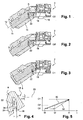
- FIG. 1 to 4 an embodiment of the antitheft device 2 according to the invention for a steering column of a motor vehicle.
- This device comprises in particular a key lock or similar member, not shown.
- the driver of the vehicle introduces the key into the lock, it rotates a rotor of the latter to turn the vehicle on and in operation.
- the device comprises in particular a bolt 8 having a general shape of rectangular parallelepiped and slidably mounted in a bolt guide 10. The sliding is carried out in a longitudinal direction 12 of the bolt.
- the bolt When in the extended position as shown in figure 1 , the bolt, by means of its distal end 14, engages with a member of the steering column of the vehicle to lock it in rotation about its axis of rotation.
- Actuation of the lock by means of the key makes it possible to control the position of the bolt and thus the blocking or unblocking of the steering column.
- Actuation of the lock by means of the key makes it possible to control the position of the bolt and thus the blocking or unblocking of the steering column.
- the device 2 comprises a housing 16 including in particular an actuator 18 for operating the bolt 8.
- the actuator 18 is formed in this case by a pull tab, which has an elongated rectilinear shape over most of its length. in a direction 20.
- the pull tab is slidably movable relative to the housing 16 in this direction.
- the actuator has a distal end 22 curved and engaged in a cavity 24 of a proximal end of the bolt.
- the bolt 8 has, in this case, two surfaces 26 and 28 forming ramps for the end 22 forming a follower intended to bear against these ramps.
- Each of the ramps 26 and 28 has, in this case, a preferentially flat shape.
- the two ramps extend opposite and at a distance from one another, and are inclined with respect to each other.
- the cavity having a general profile in "U”, the two ramps form the inner faces of the branches of the "U", the cavity being open downwards in this case.
- the bottom of the cavity has a rounded shape.
- the ramp 26, the leftmost on the figure 4 is directed to the right. It is used to actuate the bolt by the actuator for its placement in blocking position.
- the ramp 28, located rightmost and oriented to the left, is used to actuate the bolt by the actuator so that it leaves the locking position.
- the cavity 24 has a greater width in its middle part than in the lower part, at its open end.
- the median part is the part occupied by the follower 22 in the position of the Figures 1 and 4 . In this position, in fact, the width of the cavity and that of the follower, measured according to the direction 20, are such that the width of the cavity exceeds the distance m the width of the follower.
- the follower is in contact by its left face with the ramp 26 without being in contact by its right face with the ramp 28.
- the two ramps are approaching one another towards the lower end opening of the cavity.
- the device works as follows. It is assumed that the pieces are initially in the position of the figure 1 , which illustrates the bolt 8 and the actuator 18 before the start of the displacement. Both bodies are at the end of the race.
- the bolt 8 is in the position in which it blocks the operation of the column.
- the actuator 18 is in the position it has reached to place the bolt 8 in this blocking position.
- the follower 22 bears against the upper part of the ramp 26.
- the driver introduces the ignition key in the lock and turns the key, which in particular causes the unblocking of the steering column.
- the actuator 18 begins a movement in the opposite direction to that of the bolt, to the right in the figures.
- the first phase of this displacement places the actuator in the position illustrated in FIG. figure 2 . During this phase, he travels the distance m.
- the follower therefore leaves the ramp 26 and comes into contact with the ramp 28. During this movement, the bolt is not operated by the actuator.
- This first phase of displacement is therefore a dead race of the latter.
- the following is a second phase in which the pieces move from the position of the figure 2 to that of the figure 3 .
- the follower 22 remains in support on the ramp 28. It moves in the direction 20 and forces the bolt 8 to slide in the bolt guide 10 in the direction 14, in the figures up and to the right. The follower therefore travels the ramp 28 down. The bolt thus leaves the locking position and releases the column.
- the figure 3 illustrates the actuator 18 and the bolt 8 when they have reached their end of stroke.
- the follower 22 is at the lower end emerging from the cavity 24.
- the actuator 18 moves towards the bolt to the left.
- the follower 22 being from the start in contact with the ramp 26, the beginning of the movement of the actuator immediately begins a movement of the bolt towards its blocking position, without any dead stroke or with a slight clearance of about 0 , 5 mm between the follower and the ramp 26.
- the follower 22 rises along the ramp 26. This movement continues until the arrival of the bolt in its locking position as shown in FIG. figure 1 .
- t0, t0 'and t1 have been designated as the moments corresponding to Figures 1, 2 and 3 and by c0, c0 'and c1, the configurations of the pieces in these three figures.
- the line 30 illustrates the movement of the actuator 18 while the curve 32 formed of three straight segments illustrates the movement of the bolt.
- the movement of the actuator 18 is performed at the same speed to place the bolt in the locking position and to make it leave.
- the movement of the actuator is performed at a constant speed and without interruption or dead stroke in each direction of movement.
- the actuator moves while the bolt remains stationary.
- the two pieces move simultaneously.
- the figure 5 shows that the speed of the bolt is greater, between times t0 'and t1, namely to go from the configuration of the figure 2 to that of the figure 3 , that its speed in the opposite direction at any time of the displacement. This makes sense insofar as the bolt has remained stationary during the interval t0-t0 'and must therefore catch up during the next interval.
- the actuator 18 moves slightly to the right for example if the right part of the antitheft device has been broken. But the dead stroke of the bolt between times t0 and t0 'keeps the bolt stationary during the triggering of the super conviction function.
- the steering column remains immobilized. The mechanism thus incorporates somehow a retarder of the movement of the bolt relative to that of the actuator.
- a dead stroke m between 1.5 mm and 3 mm provides a particularly strong probability of such a super judgment of the bolt
- a further preferred interval for the race m is an interval ranging from 1.8 to 2.2 mm.
- the invention can materialize in a modification of the mechanical interaction between the bolt and the actuator without being modified the overall rise stroke of the latch in normal operation. Similarly, the trajectories of the parts remain the same. It is only the movement of the parts that is modified in the direction corresponding to the removal of the immobilization.
- Another type of interaction between the bolt and the actuator could be provided by ramp and follower cooperation.
- the two members may cooperate by means of at least one intermediate piece.
Landscapes
- Engineering & Computer Science (AREA)
- Mechanical Engineering (AREA)
- Lock And Its Accessories (AREA)
- Steering Controls (AREA)
Claims (10)
- Diebstahlschutzvorrichtung für eine Lenksäule eines Fahrzeuges, dadurch gekennzeichnet, dass sie Folgendes umfasst:- einen Bolzen (8), der eine Stellung zur Blockierung einer Lenksäule einnehmen kann; und- einen Aktuator (18) zum Betätigen des Bolzens,wobei die Vorrichtung derart angeordnet ist, dass eine Verschiebung des Aktuators (18), damit der Bolzen (8) die Blockierstellung verlässt, ausgehend von einer Stellung, in der er den Bolzen in die Blockierstellung platziert hat, mit einem Totgang (m) beginnt, der keine Verschiebung des Bolzens herbeiführt, und derart, dass jegliche Verschiebung des Aktuators (18) zum Platzieren des Bolzens (8) in die Blockierstellung ohne Totgang erfolgt.
- Vorrichtung nach dem vorhergehenden Anspruch, die derart angeordnet ist, dass bei gleicher Verschiebungsgeschwindigkeit des Aktuators (18) eine Verschiebung des Bolzens (8) mittels des Aktuators in einer Richtung aus der Blockierstellung bei einer sehr viel höheren Geschwindigkeit erfolgt, als in einer Richtung in diese Stellung.
- Vorrichtung nach mindestens einem der vorhergehenden Ansprüche, die derart angeordnet ist, dass der Aktuator (18) mit dem Bolzen (8) zu dessen Verschiebung direkt zusammenwirkt.
- Vorrichtung nach mindestens einem der vorhergehenden Ansprüche, die derart angeordnet ist, dass der Aktuator (18) mit dem Bolzen (8) über eine Rampenwirkung zusammenwirkt.
- Vorrichtung nach mindestens einem der vorhergehenden Ansprüche, wobei der Bolzen (8) mindestens eine Rampe (26, 28) aufweist.
- Vorrichtung nach mindestens einem der vorhergehenden Ansprüche, die mindestens eine ebene Rampe (26, 28) zum Betätigen des Bolzens (8) in Richtung der Blockierstellung und/oder in der Blockierstellung entgegengesetzter Richtung aufweist.
- Vorrichtung nach mindestens einem der vorhergehenden Ansprüche, die zum Betätigen des Bolzens (8) zwei bezüglich einander geneigte ebene Rampen (26, 28) aufweist.
- Vorrichtung nach mindestens einem der vorhergehenden Ansprüche, wobei sich der Aktuator (18) in einem Hohlraum (24) des Bolzens erstreckt.
- Vorrichtung nach einem der vorhergehenden Ansprüche, dadurch gekennzeichnet, dass der Totgang einen Wert zwischen 1,5 und 3 mm aufweist.
- Vorrichtung nach einem der vorhergehenden Ansprüche, dadurch gekennzeichnet, dass der Totgang einen Wert zwischen 1,8 und 2,2 mm aufweist.
Applications Claiming Priority (2)
| Application Number | Priority Date | Filing Date | Title |
|---|---|---|---|
| FR0905313A FR2952006B1 (fr) | 2009-11-05 | 2009-11-05 | Dispositif antivol pour colonne de direction de vehicule muni d'un actionnneur de pene a course morte |
| PCT/EP2010/065818 WO2011054672A1 (fr) | 2009-11-05 | 2010-10-20 | Dispositif antivol pour colonne de direction de véhicule muni d'un actionneur de pêne à course morte |
Publications (2)
| Publication Number | Publication Date |
|---|---|
| EP2496447A1 EP2496447A1 (de) | 2012-09-12 |
| EP2496447B1 true EP2496447B1 (de) | 2014-02-26 |
Family
ID=41688774
Family Applications (1)
| Application Number | Title | Priority Date | Filing Date |
|---|---|---|---|
| EP20100766294 Not-in-force EP2496447B1 (de) | 2009-11-05 | 2010-10-20 | Diebstahlschutzvorrichtung für eine lenksäule eines fahrzeuges mit einem antrieb für einen totgehenden riegel |
Country Status (9)
| Country | Link |
|---|---|
| US (1) | US20120266637A1 (de) |
| EP (1) | EP2496447B1 (de) |
| JP (1) | JP5669029B2 (de) |
| BR (1) | BR112012005332A2 (de) |
| ES (1) | ES2463829T3 (de) |
| FR (1) | FR2952006B1 (de) |
| IN (1) | IN2012DN02850A (de) |
| RU (1) | RU2552568C2 (de) |
| WO (1) | WO2011054672A1 (de) |
Families Citing this family (1)
| Publication number | Priority date | Publication date | Assignee | Title |
|---|---|---|---|---|
| EP2974912A1 (de) * | 2014-07-16 | 2016-01-20 | U-Shin France | Diebstahlsicherungsvorrichtung für die Lenksäule eines Fahrzeugs einem Bolzen, der sich mit einem niedrigen Schlüsseldrehmoment anhebt |
Family Cites Families (22)
| Publication number | Priority date | Publication date | Assignee | Title |
|---|---|---|---|---|
| US839584A (en) * | 1905-12-02 | 1906-12-25 | Samuel Hayford | Bicycle-lock. |
| FR2476003A2 (fr) * | 1980-01-14 | 1981-08-21 | Sodex Magister Expl Brevets Ne | Perfectionnements aux antivols pour vehicules automobiles |
| JP2537511Y2 (ja) * | 1991-03-15 | 1997-06-04 | 株式会社東海理化電機製作所 | ステアリングロック装置 |
| JP3585550B2 (ja) * | 1994-02-03 | 2004-11-04 | 本田技研工業株式会社 | 車両用キースイッチ装置 |
| FR2748054B1 (fr) * | 1996-04-29 | 1998-05-22 | Valeo Securite Habitacle | Dispositif de verrouillage motorise pour vehicule automobile comportant des moyens perfectionnes de limitation de la course du pene |
| FR2776976B1 (fr) * | 1998-04-07 | 2000-05-05 | Antivols Simplex Sa | Antivol pour une colonne de direction de vehicule comportant des moyens perfectionnes de fixation d'un mecanisme d'antivol |
| FR2799426B1 (fr) * | 1999-09-17 | 2001-12-07 | Valeo Securite Habitacle | Antivol de direction de vehicule automobile |
| US6467319B1 (en) * | 1999-11-08 | 2002-10-22 | Methode Electronics, Inc. | Remote key interlock system |
| DE10030688C1 (de) * | 2000-06-23 | 2001-10-18 | Huf Huelsbeck & Fuerst Gmbh | Schloß, insbesondere zum Verriegeln der Lenkspindel oder der Zahnstange des Lenkgetriebes oder der Ausgangswelle des Antriebsgetriebes eines Kraftfahrzeugs |
| DE10121714C1 (de) * | 2001-05-04 | 2003-01-02 | Huf Huelsbeck & Fuerst Gmbh | Schloß, insbesondere zum Verriegeln der Lenkspindel eines Kraftfahrzeugs |
| DE10247803B3 (de) * | 2002-10-14 | 2004-01-29 | Huf Hülsbeck & Fürst Gmbh & Co. Kg | Vorrichtung zum Sperren der Lenkspindel eines Kraftfahrzeugs |
| US7140213B2 (en) * | 2004-02-21 | 2006-11-28 | Strattec Security Corporation | Steering column lock apparatus and method |
| JP4348245B2 (ja) * | 2004-07-08 | 2009-10-21 | 株式会社東海理化電機製作所 | ステアリングロック装置 |
| FR2885632B1 (fr) * | 2005-05-13 | 2007-06-22 | Valeo Securite Habitacle Sas | Pene surmoule pour antivol de direction et son procede de fabrication |
| JP4671789B2 (ja) * | 2005-07-07 | 2011-04-20 | 株式会社ユーシン | ステアリングロック装置 |
| JP2007247314A (ja) * | 2006-03-17 | 2007-09-27 | Tokai Rika Co Ltd | ステアリングロック装置 |
| JP2008074306A (ja) * | 2006-09-22 | 2008-04-03 | Tokai Rika Co Ltd | ステアリングロック装置 |
| FR2909951B1 (fr) * | 2006-12-19 | 2009-03-20 | Valeo Securite Habitacle Sas | Antivol de securite pour vehicule. |
| JP2009133073A (ja) * | 2007-11-29 | 2009-06-18 | Yuhshin Co Ltd | ステアリングロック装置 |
| JP5465851B2 (ja) * | 2008-08-05 | 2014-04-09 | 株式会社アルファ | ステアリングロック装置 |
| JP5385724B2 (ja) * | 2008-08-29 | 2014-01-08 | 株式会社アルファ | ステアリングロック装置 |
| US8424348B2 (en) * | 2010-01-27 | 2013-04-23 | Strattec Security Corporation | Steering lock |
-
2009
- 2009-11-05 FR FR0905313A patent/FR2952006B1/fr not_active Expired - Fee Related
-
2010
- 2010-10-20 JP JP2012535746A patent/JP5669029B2/ja not_active Expired - Fee Related
- 2010-10-20 US US13/497,265 patent/US20120266637A1/en not_active Abandoned
- 2010-10-20 ES ES10766294T patent/ES2463829T3/es active Active
- 2010-10-20 EP EP20100766294 patent/EP2496447B1/de not_active Not-in-force
- 2010-10-20 BR BR112012005332A patent/BR112012005332A2/pt not_active IP Right Cessation
- 2010-10-20 WO PCT/EP2010/065818 patent/WO2011054672A1/fr not_active Ceased
- 2010-10-20 RU RU2012122995/11A patent/RU2552568C2/ru not_active IP Right Cessation
-
2012
- 2012-04-03 IN IN2850DEN2012 patent/IN2012DN02850A/en unknown
Also Published As
| Publication number | Publication date |
|---|---|
| WO2011054672A1 (fr) | 2011-05-12 |
| RU2552568C2 (ru) | 2015-06-10 |
| RU2012122995A (ru) | 2013-12-10 |
| ES2463829T3 (es) | 2014-05-29 |
| JP2013510028A (ja) | 2013-03-21 |
| BR112012005332A2 (pt) | 2016-03-22 |
| IN2012DN02850A (de) | 2015-07-24 |
| FR2952006B1 (fr) | 2012-01-06 |
| EP2496447A1 (de) | 2012-09-12 |
| US20120266637A1 (en) | 2012-10-25 |
| FR2952006A1 (fr) | 2011-05-06 |
| JP5669029B2 (ja) | 2015-02-12 |
Similar Documents
| Publication | Publication Date | Title |
|---|---|---|
| EP2611978B1 (de) | Fahrzeugtürgriff mit träger masse | |
| EP2496448B1 (de) | Diebstahlsicherungsvorrichtung für die lenksäule eines fahrzeugs mit supersperrung durch einen zwischenschwingarm | |
| EP2616616B1 (de) | Kraftfahrzeugsgriff mit einem trägheitskörper und einer sicherung | |
| FR2969200A1 (fr) | Procede d'actionnement d'un ensemble de battant d'un vehicule automobile | |
| EP1167135B1 (de) | Lenksäulendiebstahlsicherung mit Mittel zur Bolzenverriegelung | |
| EP2322812A1 (de) | Vorrichtung zur Klauenverriegelung mit Drehverriegelungskupplung | |
| EP3034723B1 (de) | Schloss für einen Öffnungsflügel eines Kraftfahrzeugs | |
| EP2341204B1 (de) | Verriegelungsvorrichtung für eine Motorhaube | |
| EP1863989B1 (de) | Schloss mit einem einzigen schalter | |
| FR2871125A1 (fr) | Dispositif de blocage de direction entraine par moteur | |
| EP2496447B1 (de) | Diebstahlschutzvorrichtung für eine lenksäule eines fahrzeuges mit einem antrieb für einen totgehenden riegel | |
| EP2496449B1 (de) | Lenkradschloss für eine fahrzeuglenksäule mit eine wegfahrsperre mittels ein kipphebel | |
| EP2750938B1 (de) | Diebstahlschutzeinrichtung für eine lenksäule und zugehörige lenksäule | |
| EP2736772B1 (de) | Diebstahlsicherung für eine lenksäule und zugehörige lenksäule | |
| EP1569828B1 (de) | Diebstahlvorrichtung, insbesondere eine elektronische, für ein kraftfahrzeug | |
| EP1637415B2 (de) | Elektrische Vorrichtung für das Verriegeln/Entriegeln einer Lenksäule | |
| FR3060091A1 (fr) | Dispositif de blocage mecanique d'un arbre de transmission d'un vehicule automobile | |
| FR3019847A1 (fr) | Systeme d'articulation a vitesse d'ouverture controlee, notamment pour ouverture de capot de vehicule automobile | |
| WO2016091587A1 (fr) | Serrure pour un ouvrant de véhicule automobile | |
| EP2704926B1 (de) | Diebstahlschutzvorrichtung für lenksäule und entsprechende lenksäule | |
| FR3077358A1 (fr) | Dispositif de blocage mecanique d'un arbre de transmission en position de parking | |
| FR2916139A1 (fr) | Meuble deplacable a roue motrice et directrice | |
| FR2884794A1 (fr) | Dispositif de centrage de train directionnel de vehicule reversible |
Legal Events
| Date | Code | Title | Description |
|---|---|---|---|
| PUAI | Public reference made under article 153(3) epc to a published international application that has entered the european phase |
Free format text: ORIGINAL CODE: 0009012 |
|
| 17P | Request for examination filed |
Effective date: 20120503 |
|
| AK | Designated contracting states |
Kind code of ref document: A1 Designated state(s): AL AT BE BG CH CY CZ DE DK EE ES FI FR GB GR HR HU IE IS IT LI LT LU LV MC MK MT NL NO PL PT RO RS SE SI SK SM TR |
|
| DAX | Request for extension of the european patent (deleted) | ||
| GRAP | Despatch of communication of intention to grant a patent |
Free format text: ORIGINAL CODE: EPIDOSNIGR1 |
|
| INTG | Intention to grant announced |
Effective date: 20130717 |
|
| GRAS | Grant fee paid |
Free format text: ORIGINAL CODE: EPIDOSNIGR3 |
|
| GRAA | (expected) grant |
Free format text: ORIGINAL CODE: 0009210 |
|
| AK | Designated contracting states |
Kind code of ref document: B1 Designated state(s): AL AT BE BG CH CY CZ DE DK EE ES FI FR GB GR HR HU IE IS IT LI LT LU LV MC MK MT NL NO PL PT RO RS SE SI SK SM TR |
|
| REG | Reference to a national code |
Ref country code: GB Ref legal event code: FG4D Free format text: NOT ENGLISH |
|
| REG | Reference to a national code |
Ref country code: CH Ref legal event code: EP |
|
| REG | Reference to a national code |
Ref country code: AT Ref legal event code: REF Ref document number: 653402 Country of ref document: AT Kind code of ref document: T Effective date: 20140315 |
|
| REG | Reference to a national code |
Ref country code: DE Ref legal event code: R096 Ref document number: 602010013806 Country of ref document: DE Effective date: 20140403 |
|
| REG | Reference to a national code |
Ref country code: IE Ref legal event code: FG4D Free format text: LANGUAGE OF EP DOCUMENT: FRENCH |
|
| RAP2 | Party data changed (patent owner data changed or rights of a patent transferred) |
Owner name: U-SHIN FRANCE |
|
| REG | Reference to a national code |
Ref country code: ES Ref legal event code: FG2A Ref document number: 2463829 Country of ref document: ES Kind code of ref document: T3 Effective date: 20140529 |
|
| REG | Reference to a national code |
Ref country code: NL Ref legal event code: VDEP Effective date: 20140226 |
|
| REG | Reference to a national code |
Ref country code: AT Ref legal event code: MK05 Ref document number: 653402 Country of ref document: AT Kind code of ref document: T Effective date: 20140226 |
|
| REG | Reference to a national code |
Ref country code: LT Ref legal event code: MG4D |
|
| PG25 | Lapsed in a contracting state [announced via postgrant information from national office to epo] |
Ref country code: NO Free format text: LAPSE BECAUSE OF FAILURE TO SUBMIT A TRANSLATION OF THE DESCRIPTION OR TO PAY THE FEE WITHIN THE PRESCRIBED TIME-LIMIT Effective date: 20140526 Ref country code: IS Free format text: LAPSE BECAUSE OF FAILURE TO SUBMIT A TRANSLATION OF THE DESCRIPTION OR TO PAY THE FEE WITHIN THE PRESCRIBED TIME-LIMIT Effective date: 20140626 Ref country code: LT Free format text: LAPSE BECAUSE OF FAILURE TO SUBMIT A TRANSLATION OF THE DESCRIPTION OR TO PAY THE FEE WITHIN THE PRESCRIBED TIME-LIMIT Effective date: 20140226 |
|
| PG25 | Lapsed in a contracting state [announced via postgrant information from national office to epo] |
Ref country code: CY Free format text: LAPSE BECAUSE OF FAILURE TO SUBMIT A TRANSLATION OF THE DESCRIPTION OR TO PAY THE FEE WITHIN THE PRESCRIBED TIME-LIMIT Effective date: 20140226 Ref country code: FI Free format text: LAPSE BECAUSE OF FAILURE TO SUBMIT A TRANSLATION OF THE DESCRIPTION OR TO PAY THE FEE WITHIN THE PRESCRIBED TIME-LIMIT Effective date: 20140226 Ref country code: SE Free format text: LAPSE BECAUSE OF FAILURE TO SUBMIT A TRANSLATION OF THE DESCRIPTION OR TO PAY THE FEE WITHIN THE PRESCRIBED TIME-LIMIT Effective date: 20140226 Ref country code: AT Free format text: LAPSE BECAUSE OF FAILURE TO SUBMIT A TRANSLATION OF THE DESCRIPTION OR TO PAY THE FEE WITHIN THE PRESCRIBED TIME-LIMIT Effective date: 20140226 Ref country code: PT Free format text: LAPSE BECAUSE OF FAILURE TO SUBMIT A TRANSLATION OF THE DESCRIPTION OR TO PAY THE FEE WITHIN THE PRESCRIBED TIME-LIMIT Effective date: 20140626 Ref country code: NL Free format text: LAPSE BECAUSE OF FAILURE TO SUBMIT A TRANSLATION OF THE DESCRIPTION OR TO PAY THE FEE WITHIN THE PRESCRIBED TIME-LIMIT Effective date: 20140226 |
|
| PG25 | Lapsed in a contracting state [announced via postgrant information from national office to epo] |
Ref country code: LV Free format text: LAPSE BECAUSE OF FAILURE TO SUBMIT A TRANSLATION OF THE DESCRIPTION OR TO PAY THE FEE WITHIN THE PRESCRIBED TIME-LIMIT Effective date: 20140226 Ref country code: HR Free format text: LAPSE BECAUSE OF FAILURE TO SUBMIT A TRANSLATION OF THE DESCRIPTION OR TO PAY THE FEE WITHIN THE PRESCRIBED TIME-LIMIT Effective date: 20140226 Ref country code: RS Free format text: LAPSE BECAUSE OF FAILURE TO SUBMIT A TRANSLATION OF THE DESCRIPTION OR TO PAY THE FEE WITHIN THE PRESCRIBED TIME-LIMIT Effective date: 20140226 |
|
| PG25 | Lapsed in a contracting state [announced via postgrant information from national office to epo] |
Ref country code: RO Free format text: LAPSE BECAUSE OF FAILURE TO SUBMIT A TRANSLATION OF THE DESCRIPTION OR TO PAY THE FEE WITHIN THE PRESCRIBED TIME-LIMIT Effective date: 20140226 Ref country code: CZ Free format text: LAPSE BECAUSE OF FAILURE TO SUBMIT A TRANSLATION OF THE DESCRIPTION OR TO PAY THE FEE WITHIN THE PRESCRIBED TIME-LIMIT Effective date: 20140226 Ref country code: EE Free format text: LAPSE BECAUSE OF FAILURE TO SUBMIT A TRANSLATION OF THE DESCRIPTION OR TO PAY THE FEE WITHIN THE PRESCRIBED TIME-LIMIT Effective date: 20140226 Ref country code: DK Free format text: LAPSE BECAUSE OF FAILURE TO SUBMIT A TRANSLATION OF THE DESCRIPTION OR TO PAY THE FEE WITHIN THE PRESCRIBED TIME-LIMIT Effective date: 20140226 |
|
| REG | Reference to a national code |
Ref country code: DE Ref legal event code: R097 Ref document number: 602010013806 Country of ref document: DE |
|
| PG25 | Lapsed in a contracting state [announced via postgrant information from national office to epo] |
Ref country code: PL Free format text: LAPSE BECAUSE OF FAILURE TO SUBMIT A TRANSLATION OF THE DESCRIPTION OR TO PAY THE FEE WITHIN THE PRESCRIBED TIME-LIMIT Effective date: 20140226 Ref country code: SK Free format text: LAPSE BECAUSE OF FAILURE TO SUBMIT A TRANSLATION OF THE DESCRIPTION OR TO PAY THE FEE WITHIN THE PRESCRIBED TIME-LIMIT Effective date: 20140226 |
|
| PLBE | No opposition filed within time limit |
Free format text: ORIGINAL CODE: 0009261 |
|
| STAA | Information on the status of an ep patent application or granted ep patent |
Free format text: STATUS: NO OPPOSITION FILED WITHIN TIME LIMIT |
|
| PGFP | Annual fee paid to national office [announced via postgrant information from national office to epo] |
Ref country code: GB Payment date: 20141015 Year of fee payment: 5 Ref country code: DE Payment date: 20141010 Year of fee payment: 5 Ref country code: ES Payment date: 20141021 Year of fee payment: 5 Ref country code: FR Payment date: 20141031 Year of fee payment: 5 |
|
| 26N | No opposition filed |
Effective date: 20141127 |
|
| REG | Reference to a national code |
Ref country code: DE Ref legal event code: R097 Ref document number: 602010013806 Country of ref document: DE Effective date: 20141127 |
|
| PGFP | Annual fee paid to national office [announced via postgrant information from national office to epo] |
Ref country code: IT Payment date: 20141017 Year of fee payment: 5 |
|
| PG25 | Lapsed in a contracting state [announced via postgrant information from national office to epo] |
Ref country code: LU Free format text: LAPSE BECAUSE OF FAILURE TO SUBMIT A TRANSLATION OF THE DESCRIPTION OR TO PAY THE FEE WITHIN THE PRESCRIBED TIME-LIMIT Effective date: 20141020 Ref country code: SI Free format text: LAPSE BECAUSE OF FAILURE TO SUBMIT A TRANSLATION OF THE DESCRIPTION OR TO PAY THE FEE WITHIN THE PRESCRIBED TIME-LIMIT Effective date: 20140226 Ref country code: MC Free format text: LAPSE BECAUSE OF FAILURE TO SUBMIT A TRANSLATION OF THE DESCRIPTION OR TO PAY THE FEE WITHIN THE PRESCRIBED TIME-LIMIT Effective date: 20140226 |
|
| REG | Reference to a national code |
Ref country code: CH Ref legal event code: PL |
|
| PG25 | Lapsed in a contracting state [announced via postgrant information from national office to epo] |
Ref country code: BE Free format text: LAPSE BECAUSE OF NON-PAYMENT OF DUE FEES Effective date: 20141031 |
|
| REG | Reference to a national code |
Ref country code: IE Ref legal event code: MM4A |
|
| PG25 | Lapsed in a contracting state [announced via postgrant information from national office to epo] |
Ref country code: CH Free format text: LAPSE BECAUSE OF NON-PAYMENT OF DUE FEES Effective date: 20141031 Ref country code: LI Free format text: LAPSE BECAUSE OF NON-PAYMENT OF DUE FEES Effective date: 20141031 |
|
| PG25 | Lapsed in a contracting state [announced via postgrant information from national office to epo] |
Ref country code: IE Free format text: LAPSE BECAUSE OF NON-PAYMENT OF DUE FEES Effective date: 20141020 |
|
| PG25 | Lapsed in a contracting state [announced via postgrant information from national office to epo] |
Ref country code: SM Free format text: LAPSE BECAUSE OF FAILURE TO SUBMIT A TRANSLATION OF THE DESCRIPTION OR TO PAY THE FEE WITHIN THE PRESCRIBED TIME-LIMIT Effective date: 20140226 |
|
| REG | Reference to a national code |
Ref country code: DE Ref legal event code: R119 Ref document number: 602010013806 Country of ref document: DE |
|
| GBPC | Gb: european patent ceased through non-payment of renewal fee |
Effective date: 20151020 |
|
| PG25 | Lapsed in a contracting state [announced via postgrant information from national office to epo] |
Ref country code: BG Free format text: LAPSE BECAUSE OF FAILURE TO SUBMIT A TRANSLATION OF THE DESCRIPTION OR TO PAY THE FEE WITHIN THE PRESCRIBED TIME-LIMIT Effective date: 20140226 Ref country code: GR Free format text: LAPSE BECAUSE OF FAILURE TO SUBMIT A TRANSLATION OF THE DESCRIPTION OR TO PAY THE FEE WITHIN THE PRESCRIBED TIME-LIMIT Effective date: 20140527 |
|
| PG25 | Lapsed in a contracting state [announced via postgrant information from national office to epo] |
Ref country code: MT Free format text: LAPSE BECAUSE OF FAILURE TO SUBMIT A TRANSLATION OF THE DESCRIPTION OR TO PAY THE FEE WITHIN THE PRESCRIBED TIME-LIMIT Effective date: 20140226 Ref country code: DE Free format text: LAPSE BECAUSE OF NON-PAYMENT OF DUE FEES Effective date: 20160503 Ref country code: TR Free format text: LAPSE BECAUSE OF FAILURE TO SUBMIT A TRANSLATION OF THE DESCRIPTION OR TO PAY THE FEE WITHIN THE PRESCRIBED TIME-LIMIT Effective date: 20140226 Ref country code: GB Free format text: LAPSE BECAUSE OF NON-PAYMENT OF DUE FEES Effective date: 20151020 Ref country code: IT Free format text: LAPSE BECAUSE OF NON-PAYMENT OF DUE FEES Effective date: 20151020 Ref country code: HU Free format text: LAPSE BECAUSE OF FAILURE TO SUBMIT A TRANSLATION OF THE DESCRIPTION OR TO PAY THE FEE WITHIN THE PRESCRIBED TIME-LIMIT; INVALID AB INITIO Effective date: 20101020 |
|
| REG | Reference to a national code |
Ref country code: FR Ref legal event code: ST Effective date: 20160630 |
|
| PG25 | Lapsed in a contracting state [announced via postgrant information from national office to epo] |
Ref country code: FR Free format text: LAPSE BECAUSE OF NON-PAYMENT OF DUE FEES Effective date: 20151102 |
|
| REG | Reference to a national code |
Ref country code: ES Ref legal event code: FD2A Effective date: 20161125 |
|
| PG25 | Lapsed in a contracting state [announced via postgrant information from national office to epo] |
Ref country code: ES Free format text: LAPSE BECAUSE OF NON-PAYMENT OF DUE FEES Effective date: 20151021 |
|
| PG25 | Lapsed in a contracting state [announced via postgrant information from national office to epo] |
Ref country code: MK Free format text: LAPSE BECAUSE OF FAILURE TO SUBMIT A TRANSLATION OF THE DESCRIPTION OR TO PAY THE FEE WITHIN THE PRESCRIBED TIME-LIMIT Effective date: 20140226 |
|
| PG25 | Lapsed in a contracting state [announced via postgrant information from national office to epo] |
Ref country code: AL Free format text: LAPSE BECAUSE OF FAILURE TO SUBMIT A TRANSLATION OF THE DESCRIPTION OR TO PAY THE FEE WITHIN THE PRESCRIBED TIME-LIMIT Effective date: 20140226 |