EP3666609A1 - Véhicule de travail - Google Patents
Véhicule de travail Download PDFInfo
- Publication number
- EP3666609A1 EP3666609A1 EP19211126.8A EP19211126A EP3666609A1 EP 3666609 A1 EP3666609 A1 EP 3666609A1 EP 19211126 A EP19211126 A EP 19211126A EP 3666609 A1 EP3666609 A1 EP 3666609A1
- Authority
- EP
- European Patent Office
- Prior art keywords
- link
- drive shaft
- braking
- axle
- pivot
- Prior art date
- Legal status (The legal status is an assumption and is not a legal conclusion. Google has not performed a legal analysis and makes no representation as to the accuracy of the status listed.)
- Granted
Links
Images



Classifications
-
- F—MECHANICAL ENGINEERING; LIGHTING; HEATING; WEAPONS; BLASTING
- F16—ENGINEERING ELEMENTS AND UNITS; GENERAL MEASURES FOR PRODUCING AND MAINTAINING EFFECTIVE FUNCTIONING OF MACHINES OR INSTALLATIONS; THERMAL INSULATION IN GENERAL
- F16H—GEARING
- F16H48/00—Differential gearings
- F16H48/20—Arrangements for suppressing or influencing the differential action, e.g. locking devices
- F16H48/24—Arrangements for suppressing or influencing the differential action, e.g. locking devices using positive clutches or brakes
-
- B—PERFORMING OPERATIONS; TRANSPORTING
- B60—VEHICLES IN GENERAL
- B60T—VEHICLE BRAKE CONTROL SYSTEMS OR PARTS THEREOF; BRAKE CONTROL SYSTEMS OR PARTS THEREOF, IN GENERAL; ARRANGEMENT OF BRAKING ELEMENTS ON VEHICLES IN GENERAL; PORTABLE DEVICES FOR PREVENTING UNWANTED MOVEMENT OF VEHICLES; VEHICLE MODIFICATIONS TO FACILITATE COOLING OF BRAKES
- B60T1/00—Arrangements of braking elements, i.e. of those parts where braking effect occurs specially for vehicles
- B60T1/02—Arrangements of braking elements, i.e. of those parts where braking effect occurs specially for vehicles acting by retarding wheels
- B60T1/06—Arrangements of braking elements, i.e. of those parts where braking effect occurs specially for vehicles acting by retarding wheels acting otherwise than on tread, e.g. employing rim, drum, disc, or transmission or on double wheels
- B60T1/062—Arrangements of braking elements, i.e. of those parts where braking effect occurs specially for vehicles acting by retarding wheels acting otherwise than on tread, e.g. employing rim, drum, disc, or transmission or on double wheels acting on transmission parts
-
- B—PERFORMING OPERATIONS; TRANSPORTING
- B60—VEHICLES IN GENERAL
- B60T—VEHICLE BRAKE CONTROL SYSTEMS OR PARTS THEREOF; BRAKE CONTROL SYSTEMS OR PARTS THEREOF, IN GENERAL; ARRANGEMENT OF BRAKING ELEMENTS ON VEHICLES IN GENERAL; PORTABLE DEVICES FOR PREVENTING UNWANTED MOVEMENT OF VEHICLES; VEHICLE MODIFICATIONS TO FACILITATE COOLING OF BRAKES
- B60T8/00—Arrangements for adjusting wheel-braking force to meet varying vehicular or ground-surface conditions, e.g. limiting or varying distribution of braking force
- B60T8/32—Arrangements for adjusting wheel-braking force to meet varying vehicular or ground-surface conditions, e.g. limiting or varying distribution of braking force responsive to a speed condition, e.g. acceleration or deceleration
- B60T8/321—Arrangements for adjusting wheel-braking force to meet varying vehicular or ground-surface conditions, e.g. limiting or varying distribution of braking force responsive to a speed condition, e.g. acceleration or deceleration deceleration
- B60T8/3215—Systems characterised by having means acting on components of the drive line, e.g. retarder, clutch or differential gear
-
- F—MECHANICAL ENGINEERING; LIGHTING; HEATING; WEAPONS; BLASTING
- F16—ENGINEERING ELEMENTS AND UNITS; GENERAL MEASURES FOR PRODUCING AND MAINTAINING EFFECTIVE FUNCTIONING OF MACHINES OR INSTALLATIONS; THERMAL INSULATION IN GENERAL
- F16H—GEARING
- F16H48/00—Differential gearings
- F16H48/06—Differential gearings with gears having orbital motion
- F16H48/08—Differential gearings with gears having orbital motion comprising bevel gears
Definitions
- the present invention relates to a working vehicle.
- a working vehicle which includes a left brake and a right brake for respectively braking left and right rear wheels and one of these brakes generates a braking force when a left brake pedal or a right brake pedal is depressed (e.g., see JP-A-11-192849 ).
- the left brake pedal and the right brake pedal can be connected to generate a braking force simultaneously on the left and right brakes.
- the present invention has been made in view of the above problem, and an object thereof is to provide a working vehicle having a compact braking device.
- a working vehicle (1) includes a drive shaft part (22) to which power generated by a power source (13) is transmitted and which transmits the power to drive wheels (8) via a differential device (25), and a drive shaft braking mechanism (20) which generates a braking force on the drive shaft part (22) when a brake pedal (81) is depressed.
- the braking device of the working vehicle can be made compact.
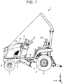
- FIG. 1 is a schematic side view of the working vehicle 1. Meanwhile, in the following description, a tractor 1 will be described as an example of the working vehicle 1.
- a front and rear direction with a positive Y-axis direction as the front side and a negative Y-axis direction as the rear side is defined, and a left and right direction with a positive X-axis direction as the right side and a negative X-axis direction as the left side is defined.
- an upper and lower direction with a positive Z-axis direction as the upper side and a negative Z-axis direction as the lower side is defined.
- front and rear direction refers to the front and rear direction of the tractor 1. More specifically, the front and rear direction refers to the travel direction when the tractor 1 goes straight.
- the front side in the travel direction is defined as “the front,” and the rear side is defined as “the rear.”
- the left hand side is “the left,” and the right hand side is “the right.”
- the tractor 1 includes a front axle 3 swingably attached to the front lower side of a vehicle body frame 2, a transmission case 4 swingably attached to the rear lower side of the vehicle body frame 2, and a pair of rear axle housings 5 extending in the left and right direction from the transmission case 4.
- the front axle 3 includes a pair of left and right front wheels 7.
- the rear axle housing 5 includes a pair of left and right rear wheels 8.
- the tractor 1 includes a step floor 9 at an intermediate portion of the vehicle body frame 2 in the front and rear direction.
- the seat 10 In the control part over the step floor 9, the seat 10, a control panel 11, a steering handle 12, various operation levers, and various operation pedals are provided.
- the tractor 1 includes an engine 13 (power source) supported on the vehicle body frame 2 in front of the step floor 9 and a bonnet 14 covering the engine 13.
- the tractor 1 is adapted to travel by transmitting the power generated by the engine 13 to the rear wheels 8 via a drive shaft part 22 (see FIG. 2 ) and the like.
- FIG. 2 is a view showing the configuration of the tractor 1 in the vicinity of the rear axle housing 5.
- the tractor 1 includes a drive shaft braking mechanism 20 and an axle braking mechanism 21.
- the drive shaft braking mechanism 20 brakes the rear wheels 8 by generating a braking force on the drive shaft part 22.
- the drive shaft part 22 includes a propeller shaft 23 to which the power generated by the engine 13 (see FIG. 1 ) is transmitted, and a gear part 24.
- the gear part 24 has a first gear 24b rotating together with a shaft 24a and a second gear 24c rotating together with the shaft 24a.
- the first gear 24b is a bevel gear and meshes with a bevel gear 23a provided at the tip of the propeller shaft 23.
- the second gear 24c is, for example, a spur gear and meshes with a final gear 25a of a differential device 25.
- the drive shaft braking mechanism 20 includes a disc 30 rotating together with the shaft 24a of the drive shaft part 22 and a clamping part 31 capable of clamping the disc 30 according to the pivoting of a drive shaft braking arm 15.
- the clamping part 31 has a fixed portion 31a and a movable portion 31b.
- the fixed portion 31a is fixed to the rear axle housing 5. Meanwhile, the fixed portion 31a supports the shaft 24a of the drive shaft part 22 to be rotatable via a bearing 17.
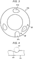
- the movable portion 31b is formed in an annular shape, as shown in FIG. 3 .
- the movable portion 31b has an engagement hole 31c with which the drive shaft braking arm 15 engages and a ball hole 31d in which a part of a ball 31e is accommodated.
- FIG. 3 is a schematic view showing the movable portion 31b.
- a plurality of ball holes 31d is formed.
- each of the ball holes 31d is formed so that its bottom surface is inclined.
- FIG. 4 is a sectional view taken along the line IV-IV in FIG. 3
- the movable portion 31b can be pivoted by the drive shaft braking arm 15.
- the movable portion 31b does not come into contact with the disc 30 when the balls 31e accommodated in the ball holes 31d are in a non-operation position where the depth of the ball holes 31d is deep. Therefore, in the case where the balls 31e are in the non-operation position, the drive shaft braking mechanism 20 does not generate a braking force on the drive shaft part 22, so that the rear wheels 8 do not brake.
- the movable portion 31b when the movable portion 31b is pivoted by the drive shaft braking arm 15 from the state where the balls 31e are in the non-operation position, the movable portion 31b moves toward the disc 30 along an axial direction of the shaft 24a with respect to the balls 31e and comes into contact with the disc 30. In this way, the clamping part 31 clamps the disc 30 and the drive shaft braking mechanism 20 generates a braking force on the drive shaft part 22 to brake the rear wheels 8.
- the axle braking mechanism 21 generates a braking force on one of axles 8a, 8b of the rear wheels 8. For example, the axle braking mechanism 21 generates a braking force on the axle 8a of the left rear wheel 8.
- the axle braking mechanism 21 includes a disc 40 rotating together with the axle 8a and a clamping part 41 capable of clamping the disc 40 according to the pivoting of an axle braking arm 16.
- the clamping part 41 has a fixed portion 41a and a movable portion 41b.
- the fixed portion 41a is fixed to the rear axle housing 5.
- the configuration of the movable portion 41b is the same as that of the movable portion 31b of the drive shaft braking mechanism 20, and detailed description thereof is omitted.
- the movable portion 41b does not come into contact with the disc 40 when balls 41c are in a non-operation position. Therefore, the axle braking mechanism 21 does not generate a braking force on the axle 8a, so that the rear wheels 8 do not brake.
- the movable portion 41b can be pivoted by the axle braking arm 16.
- the movable portion 41b moves toward the disc 40 along an axial direction of the axle 8a with respect to the balls 41c and comes into contact with the disc 40.
- the clamping part 41 clamps the disc 40 and the axle braking mechanism 21 generates a braking force on the axle 8a to brake the rear wheels 8.
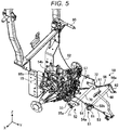
- FIG. 5 is a right front perspective view showing a part of the tractor 1.
- FIG. 6 is a left front perspective view showing a part of the tractor 1.
- the link mechanism 50 includes a first pivot part 51, a second pivot part 52, a first link 53, a second link 54, a third link 55, a fourth link 56, and a fifth link 57.
- the first pivot part 51 includes a pivot shaft 60, a first pivot plate 61, and a second pivot plate 62.
- the pivot shaft 60 extends in the left and right direction and is pivotably supported on the vehicle body frame 2, for example.
- the first pivot plate 61 is attached to a right end of the pivot shaft 60 and is pivoted integrally with the pivot shaft 60.
- a first mounting hole 61a and a second mounting hole (not shown) are formed in the first pivot plate 61.
- the first mounting hole 61a is a long hole.
- the second pivot plate 62 is attached to a left end of the pivot shaft 60 and is pivoted integrally with the pivot shaft 60.
- a mounting hole 62a is formed in the second pivot plate 62.
- the mounting hole 62a is a long hole.
- the second pivot part 52 includes a pivot shaft 70, a first pivot plate 71, and a second pivot plate 72.
- the pivot shaft 70 extends in the left and right direction and is pivotably supported on the vehicle body frame 2, for example.
- the first pivot plate 71 is attached to a right end of the pivot shaft 70 and is pivoted integrally with the pivot shaft 70.
- a mounting hole 71a is formed in the first pivot plate 71.
- the mounting hole 71a is a long hole.
- the second pivot plate 72 is attached to a left end of the pivot shaft 70 and is pivoted integrally with the pivot shaft 70.
- a first mounting hole (not shown) and a second mounting hole 72a are formed in the second pivot plate 72.
- the second mounting hole 72a is a long hole.
- the second pivot plate 72 is connected to a brake lever 80 via a wire 82.
- the wire 82 is attached to the first mounting hole.
- the first link 53 connects a brake pedal 81 and the first pivot part 51. Specifically, the first link 53 connects the brake pedal 81 and the first pivot plate 61 of the first pivot part 51. The first link 53 is pivotably attached to the brake pedal 81 and the first pivot plate 61.
- a first pin 53a is provided at a front end of the first link 53 and is pivotably inserted into a mounting hole (not shown) provided in the brake pedal 81.
- a second pin 53b is provided at a rear end of the first link 53 and is slidably inserted into the first mounting hole 61a of the first pivot plate 61, as shown in FIG. 6 .
- FIG. 6 schematically shows the relationship between the first mounting hole 61a and the second pin 53b of the first link 53 and does not limit the shape or the like of the first mounting hole 61a. The same applies to the other mounting holes 62a, 71a, 72a.
- the second pin 53b of the first link 53 is provided to contact with the front end of the first mounting hole 61a.
- the second link 54 connects the first pivot part 51 and the drive shaft braking arm 15. Specifically, the second link 54 connects the first pivot plate 61 of the first pivot part 51 and the drive shaft braking arm 15.
- the second link 54 is pivotably attached to the first pivot plate 61 and the drive shaft braking arm 15.
- a first pin 54a is provided at a front end of the second link 54 and is pivotably inserted into a second mounting hole (not shown) of the first pivot plate 61.
- a second pin 54b is provided at a rear end of the second link 54 and is pivotably inserted into a first mounting hole (not shown) of the drive shaft braking arm 15.
- the third link 55 connects the second pivot part 52 and the drive shaft braking arm 15. Specifically, the third link 55 connects the first pivot plate 71 of the second pivot part 52 and the drive shaft braking arm 15. The third link 55 is pivotably attached to the first pivot plate 71 and the drive shaft braking arm 15.
- a first pin 55a is provided at a front end of the third link 55 and is slidably inserted into the mounting hole 71a of the first pivot plate 71. In the released state, the first pin 55a of the third link 55 is provided to contact with the rear end of the mounting hole 71a.
- a second pin 55b is provided at a rear end of the third link 55 and is pivotably inserted into a second mounting hole (not shown) formed in the drive shaft braking arm 15.
- the fourth link 56 connects the first pivot part 51 and the axle braking arm 16. Specifically, the fourth link 56 connects the second pivot plate 62 of the first pivot part 51 and the axle braking arm 16. The fourth link 56 is pivotably attached to the second pivot plate 62 and the axle braking arm 16.
- a first pin 56a is provided at a front end of the fourth link 56 and is slidably inserted into the mounting hole 62a of the second pivot plate 62.
- the first pin 56a of the fourth link 56 is provided so that a gap is generated between the first pin 56a and the front end of the mounting hole 62a and between the first pin 56a and the rear end of the mounting hole 62a.
- a second pin 56b is provided at a rear end of the fourth link 56 and is pivotably inserted into a first mounting hole (not shown) formed in the axle braking arm 16.
- the fifth link 57 connects the second pivot part 52 and the axle braking arm 16. Specifically, the fifth link 57 connects the second pivot plate 72 of the second pivot part 52 and the axle braking arm 16. The fifth link 57 is pivotably attached to the second pivot plate 72 and the axle braking arm 16.
- a first pin 57a is provided at a front end of the fifth link 57 and is slidably inserted into the second mounting hole 72a of the second pivot plate 72.
- the first pin 57a of the fifth link 57 is provided so that a gap is generated between the first pin 57a and the front end of the second mounting hole 72a and between the first pin 57a and the rear end of the second mounting hole 72a.
- a second pin 57b is provided at a rear end of the fifth link 57 and is pivotably inserted into a second mounting hole (not shown) formed in the axle braking arm 16.
- the link mechanism 50 generates a braking force at different timings on the drive shaft braking mechanism 20 and the axle braking mechanism 21 when the brake pedal 81 or the brake lever 80 is operated.
- FIG. 7 is a view showing the operation of the link mechanism 50 when the brake pedal 81 is operated.
- the portion of the link mechanism 50 pivoting when the brake pedal 81 is operated is indicated by a solid arrow.
- the first link 53 moves forward from the position in the released state in response to the depression of the brake pedal 81. Since the second pin 53b of the first link 53 is in contact with the front end of the first mounting hole 61a of the first pivot plate 61 in the released state (see FIG. 6 ), the first pivot part 51 is pivoted forward.
- the second link 54 attached to the second mounting hole (not shown) of the first pivot plate 61 moves forward with the pivoting of the first pivot part 51, and the drive shaft braking arm 15 is pivoted forward.
- the drive shaft braking mechanism 20 (see FIG. 2 ) generates a braking force.
- the drive shaft braking mechanism 20 generates a braking force on the drive shaft part 22 as soon as the brake pedal 81 is depressed.
- the brake pedal 81 may have such a margin that a braking force is not generated for a predetermined depression amount from the released state.
- the axle braking mechanism 21 (see FIG. 2 ) generates a braking force. That is, when the brake pedal 81 is depressed, the link mechanism 50 generates a braking force by the axle braking mechanism 21 after generating a braking force by the drive shaft braking mechanism 20.
- a gap is formed between the first pin 55a of the third link 55 and the front end of the mounting hole 71a so that the first pin 55a of the third link 55 does not come into contact with the front end of the mounting hole 71a of the first pivot plate 71 of the second pivot part 52 even when the drive shaft braking arm 15 is pivoted forward via the second link 54 and the third link 55 moves forward with the drive shaft braking arm 15. Therefore, even when the brake pedal 81 is depressed and the drive shaft braking arm 15 is pivoted, the forward pivoting of the drive shaft braking arm 15 is not transmitted to the axle braking arm 16 via the third link 55 and the second pivot part 52.
- a gap is formed between the first pin 57a of the fifth link 57 and the front end of the second mounting hole 72a so that the first pin 57a of the fifth link 57 does not contact with the front end of the second mounting hole 72a of the second pivot plate 72 of the second pivot part 52 even when the axle braking arm 16 is pivoted via the fourth link 56. Therefore, even when the brake pedal 81 is depressed and the axle braking arm 16 is pivoted, the forward pivoting of the axle braking arm 16 is not transmitted to the second pivot part 52 via the fifth link 57.
- FIG. 8 is a view showing the operation of the link mechanism 50 when the brake lever 80 is operated.
- the portion of the link mechanism 50 pivoting when the brake lever 80 is operated is indicated by a solid arrow.
- the drive shaft braking mechanism 20 (see FIG. 2 ) generates a braking force.
- the drive shaft braking mechanism 20 generates a braking force as soon as the brake lever 80 is pulled upward.
- the brake lever 80 may have such a margin that a braking force is not generated for a predetermined pulled-up amount from the released state.
- the axle braking mechanism 21 (see FIG. 2 ) generates a braking force. That is, even when the brake lever 80 is pulled upward, a braking force is generated by the axle braking mechanism 21 after a braking force is generated by the drive shaft braking mechanism 20.
- a gap is formed between the first pin 56a of the fourth link 56 and the front end of the mounting hole 62a of the second pivot plate 62 of the first pivot part 51 even when the axle braking arm 16 is pivoted forward via the fifth link 57 and the fourth link 56 moves forward with the axle braking arm 16 (see FIG. 6 ). Therefore, even when the brake lever 80 is pulled upward and the axle braking arm 16 is pivoted forward, the pivoting of the axle braking arm 16 is not transmitted to the first pivot part 51 via the fourth link 56.
- a gap is formed between the first pin 53a of the first link 53 and the rear end of the first mounting hole 61a of the first pivot plate 61 of the first pivot part 51 even when the drive shaft braking arm 15 is pivoted forward via the third link 55 and the second link 54 moves forward with the drive shaft braking arm 15 (see FIG. 6 ). Therefore, even when the brake lever 80 is pulled upward and the drive shaft braking arm 15 is pivoted, the pivoting of the drive shaft braking arm 15 is not transmitted to the first link 53.
- the brake pedal 81 does not move even when the brake lever 80 is pulled upward. Therefore, in a situation where a worker does not operate the brake pedal 81 when the brake lever 80 is pulled upward, the brake pedal 81 does not move. In this way, the tractor 1 can suppress giving an uncomfortable feeling to the worker.
- the tractor 1 includes the drive shaft part 22 for transmitting the power generated by the engine 13 to the rear wheels 8 via the differential device 25 when the brake pedal 81 is depressed, and the drive shaft braking mechanism 20 for generating a braking force on the drive shaft part 22.
- the tractor 1 can generate a braking force on the drive shaft part 22 having a smaller torque than the axles 8a, 8b and can generate a braking force by the compact drive shaft braking mechanism 20. Therefore, the tractor 1 can be reduced in size. Further, the tractor 1 can brake the left and right rear wheels 8 by a single drive shaft braking mechanism 20.
- the tractor 1 includes the axle braking mechanism 21 for generating a braking force on the axle 8a when the brake lever 80 is pulled upward.
- the tractor 1 can generate a braking force by operating the brake lever 80. For example, it is possible to prevent the tractor 1 from moving while stopped. That is, the tractor 1 can use the axle braking mechanism 21 as a parking brake. Further, the tractor 1 can generate a braking force by the compact axle braking mechanism 21. Therefore, the tractor 1 can be reduced in size.
- the tractor 1 includes the link mechanism 50 that actuates the drive shaft braking mechanism 20 and the axle braking mechanism 21 when the brake pedal 81 is depressed.
- the tractor 1 can generate a braking force by two braking mechanisms 20, 21 by operating the brake pedal 81. Therefore, the tractor 1 can stably maintain its stationary state.
- the tractor 1 includes the link mechanism 50 that actuates the drive shaft braking mechanism 20 and the axle braking mechanism 21 when the brake lever 80 is pulled upward.
- the tractor 1 can generate a braking force by two braking mechanisms 20, 21 by operating the brake lever 80. Therefore, the tractor 1 can stably maintain its stationary state.
- the tractor 1 When the brake pedal 81 or the brake lever 80 is operated, the tractor 1 operates the axle braking mechanism 21 after operating the drive shaft braking mechanism 20.
- the tractor 1 can generate a braking force on the axle 8a after a braking force is generated on the drive shaft part 22 and a vehicle speed is sufficiently lowered or the tractor is stopped. Therefore, the tractor 1 can prevent a one-side brake that generates a braking force only on the axle 8a.
- the tractor 1 according to a modification may generate a braking force only by the drive shaft braking mechanism 20 when the brake pedal 81 is depressed. In this way, the tractor 1 according to the modification can prevent a one-side brake when the brake pedal 81 is depressed during travelling.
- the working vehicle (1) includes a drive shaft part (22) to which power generated by a power source (13) is transmitted and which transmits the power to drive wheels (8) via a differential device (25), and a drive shaft braking mechanism (20) which generates a braking force on the drive shaft part (22) when a brake pedal (81) is depressed.
Landscapes
- Engineering & Computer Science (AREA)
- Mechanical Engineering (AREA)
- Transportation (AREA)
- General Engineering & Computer Science (AREA)
- Braking Elements And Transmission Devices (AREA)
- Transmission Of Braking Force In Braking Systems (AREA)
- Braking Arrangements (AREA)
Applications Claiming Priority (1)
| Application Number | Priority Date | Filing Date | Title |
|---|---|---|---|
| JP2018233148A JP6859995B2 (ja) | 2018-12-13 | 2018-12-13 | 作業車両 |
Publications (2)
| Publication Number | Publication Date |
|---|---|
| EP3666609A1 true EP3666609A1 (fr) | 2020-06-17 |
| EP3666609B1 EP3666609B1 (fr) | 2023-02-22 |
Family
ID=68655316
Family Applications (1)
| Application Number | Title | Priority Date | Filing Date |
|---|---|---|---|
| EP19211126.8A Active EP3666609B1 (fr) | 2018-12-13 | 2019-11-25 | Véhicule de travail |
Country Status (3)
| Country | Link |
|---|---|
| US (1) | US11156282B2 (fr) |
| EP (1) | EP3666609B1 (fr) |
| JP (1) | JP6859995B2 (fr) |
Families Citing this family (1)
| Publication number | Priority date | Publication date | Assignee | Title |
|---|---|---|---|---|
| JP7584378B2 (ja) * | 2021-09-07 | 2024-11-15 | 株式会社クボタ | 作業車 |
Citations (8)
| Publication number | Priority date | Publication date | Assignee | Title |
|---|---|---|---|---|
| FR2355216A1 (fr) * | 1976-06-17 | 1978-01-13 | Etudes Rech Avancees | Ensemble de transmission a dispositif de freinage, notamment pour vehicules |
| JPS6112458A (ja) * | 1984-06-28 | 1986-01-20 | Yamaha Motor Co Ltd | 後二輪を有する車両のブレ−キ装置 |
| US5673776A (en) * | 1996-03-08 | 1997-10-07 | Dana Corporation | Pinion mounted parking brake |
| JPH11192849A (ja) | 1998-01-08 | 1999-07-21 | Iseki & Co Ltd | 作業車両の前輪駆動装置 |
| US6354421B1 (en) * | 1999-12-28 | 2002-03-12 | Shin Nippon Wheel Industries Co., Ltd. | Brake system in buggy |
| DE102011014290A1 (de) * | 2010-03-18 | 2012-02-02 | Kwang Yang Motor Co., Ltd. | Fahrzeug mit Rädern (Wheeled vehicle) |
| WO2016085369A1 (fr) * | 2014-11-28 | 2016-06-02 | Volvo Construction Equipment Ab | Procédé et unité de commande permettant d'empêcher une unité de tracteur d'une machine de travail de faire des tonneaux |
| WO2018210381A1 (fr) * | 2017-05-19 | 2018-11-22 | Lucas Automotive Gmbh | Système de frein de stationnement pour véhicule à moteur et véhicule à moteur |
Family Cites Families (4)
| Publication number | Priority date | Publication date | Assignee | Title |
|---|---|---|---|---|
| US3439785A (en) * | 1966-11-14 | 1969-04-22 | Ford Motor Co | Differential lock and axle brake |
| US8056697B2 (en) * | 2006-12-22 | 2011-11-15 | Deere & Company | Brake/differential lock pedal linkage |
| US8485304B2 (en) * | 2007-09-18 | 2013-07-16 | Yanmar Co., Ltd. | Brake operation structure and brake/differential-lock operation structure |
| US8376907B2 (en) * | 2009-06-02 | 2013-02-19 | Bombardier Recreational Products Inc. | Braking system and method for a vehicle |
-
2018
- 2018-12-13 JP JP2018233148A patent/JP6859995B2/ja active Active
-
2019
- 2019-11-25 EP EP19211126.8A patent/EP3666609B1/fr active Active
- 2019-12-12 US US16/711,759 patent/US11156282B2/en not_active Expired - Fee Related
Patent Citations (8)
| Publication number | Priority date | Publication date | Assignee | Title |
|---|---|---|---|---|
| FR2355216A1 (fr) * | 1976-06-17 | 1978-01-13 | Etudes Rech Avancees | Ensemble de transmission a dispositif de freinage, notamment pour vehicules |
| JPS6112458A (ja) * | 1984-06-28 | 1986-01-20 | Yamaha Motor Co Ltd | 後二輪を有する車両のブレ−キ装置 |
| US5673776A (en) * | 1996-03-08 | 1997-10-07 | Dana Corporation | Pinion mounted parking brake |
| JPH11192849A (ja) | 1998-01-08 | 1999-07-21 | Iseki & Co Ltd | 作業車両の前輪駆動装置 |
| US6354421B1 (en) * | 1999-12-28 | 2002-03-12 | Shin Nippon Wheel Industries Co., Ltd. | Brake system in buggy |
| DE102011014290A1 (de) * | 2010-03-18 | 2012-02-02 | Kwang Yang Motor Co., Ltd. | Fahrzeug mit Rädern (Wheeled vehicle) |
| WO2016085369A1 (fr) * | 2014-11-28 | 2016-06-02 | Volvo Construction Equipment Ab | Procédé et unité de commande permettant d'empêcher une unité de tracteur d'une machine de travail de faire des tonneaux |
| WO2018210381A1 (fr) * | 2017-05-19 | 2018-11-22 | Lucas Automotive Gmbh | Système de frein de stationnement pour véhicule à moteur et véhicule à moteur |
Also Published As
| Publication number | Publication date |
|---|---|
| US11156282B2 (en) | 2021-10-26 |
| US20200191249A1 (en) | 2020-06-18 |
| JP6859995B2 (ja) | 2021-04-14 |
| JP2020093672A (ja) | 2020-06-18 |
| EP3666609B1 (fr) | 2023-02-22 |
Similar Documents
| Publication | Publication Date | Title |
|---|---|---|
| EP2266849B1 (fr) | Dispositif à pédales pour véhicule à moteur | |
| EP3666609B1 (fr) | Véhicule de travail | |
| CN115923897A (zh) | 作业机械 | |
| CN103025966B (zh) | 驾驶室及机动平地机 | |
| JP4493925B2 (ja) | 車両用パーキングレバー装置 | |
| JP2007055281A (ja) | 走行速度操作装置 | |
| JP2001278168A (ja) | 車両用前後輪ブレーキ連動装置 | |
| US11400896B2 (en) | Vehicle | |
| JP5497602B2 (ja) | 移植機 | |
| JP6920955B2 (ja) | トラクタ | |
| JP2006076535A (ja) | ブレーキ装置 | |
| US12214765B2 (en) | Support structure for brake lever, and off-road vehicle | |
| JP6374766B2 (ja) | 作業車両 | |
| JP2006056422A (ja) | 作業車輌 | |
| JP2766129B2 (ja) | 作業車の旋回操作構造 | |
| JPH11334642A (ja) | 水田作業車 | |
| JP2010073109A (ja) | 車両用ペダル装置 | |
| JP3622326B2 (ja) | パーキングブレーキ | |
| JP6766765B2 (ja) | ペダル後退抑制機構 | |
| JP2025137098A (ja) | 車両用ペダル連結構造 | |
| JP3002332B2 (ja) | 作業車のサイドブレーキ操作構造 | |
| JPH11192854A (ja) | 乗用作業車のシフトレバーガイド | |
| JP2014082980A (ja) | 乗用型走行車両における地上操作具 | |
| JP2001080380A (ja) | 作業車の走行変速構造 | |
| JP2012140104A (ja) | ターンシグナル操作装置 |
Legal Events
| Date | Code | Title | Description |
|---|---|---|---|
| PUAI | Public reference made under article 153(3) epc to a published international application that has entered the european phase |
Free format text: ORIGINAL CODE: 0009012 |
|
| STAA | Information on the status of an ep patent application or granted ep patent |
Free format text: STATUS: THE APPLICATION HAS BEEN PUBLISHED |
|
| AK | Designated contracting states |
Kind code of ref document: A1 Designated state(s): AL AT BE BG CH CY CZ DE DK EE ES FI FR GB GR HR HU IE IS IT LI LT LU LV MC MK MT NL NO PL PT RO RS SE SI SK SM TR |
|
| AX | Request for extension of the european patent |
Extension state: BA ME |
|
| STAA | Information on the status of an ep patent application or granted ep patent |
Free format text: STATUS: REQUEST FOR EXAMINATION WAS MADE |
|
| 17P | Request for examination filed |
Effective date: 20201210 |
|
| RBV | Designated contracting states (corrected) |
Designated state(s): AL AT BE BG CH CY CZ DE DK EE ES FI FR GB GR HR HU IE IS IT LI LT LU LV MC MK MT NL NO PL PT RO RS SE SI SK SM TR |
|
| STAA | Information on the status of an ep patent application or granted ep patent |
Free format text: STATUS: EXAMINATION IS IN PROGRESS |
|
| 17Q | First examination report despatched |
Effective date: 20210428 |
|
| GRAP | Despatch of communication of intention to grant a patent |
Free format text: ORIGINAL CODE: EPIDOSNIGR1 |
|
| STAA | Information on the status of an ep patent application or granted ep patent |
Free format text: STATUS: GRANT OF PATENT IS INTENDED |
|
| INTG | Intention to grant announced |
Effective date: 20220708 |
|
| GRAS | Grant fee paid |
Free format text: ORIGINAL CODE: EPIDOSNIGR3 |
|
| GRAJ | Information related to disapproval of communication of intention to grant by the applicant or resumption of examination proceedings by the epo deleted |
Free format text: ORIGINAL CODE: EPIDOSDIGR1 |
|
| GRAL | Information related to payment of fee for publishing/printing deleted |
Free format text: ORIGINAL CODE: EPIDOSDIGR3 |
|
| STAA | Information on the status of an ep patent application or granted ep patent |
Free format text: STATUS: EXAMINATION IS IN PROGRESS |
|
| INTC | Intention to grant announced (deleted) | ||
| STAA | Information on the status of an ep patent application or granted ep patent |
Free format text: STATUS: GRANT OF PATENT IS INTENDED |
|
| GRAA | (expected) grant |
Free format text: ORIGINAL CODE: 0009210 |
|
| STAA | Information on the status of an ep patent application or granted ep patent |
Free format text: STATUS: THE PATENT HAS BEEN GRANTED |
|
| AK | Designated contracting states |
Kind code of ref document: B1 Designated state(s): AL AT BE BG CH CY CZ DE DK EE ES FI FR GB GR HR HU IE IS IT LI LT LU LV MC MK MT NL NO PL PT RO RS SE SI SK SM TR |
|
| REG | Reference to a national code |
Ref country code: GB Ref legal event code: FG4D |
|
| REG | Reference to a national code |
Ref country code: CH Ref legal event code: EP |
|
| REG | Reference to a national code |
Ref country code: DE Ref legal event code: R096 Ref document number: 602019025483 Country of ref document: DE |
|
| REG | Reference to a national code |
Ref country code: AT Ref legal event code: REF Ref document number: 1549317 Country of ref document: AT Kind code of ref document: T Effective date: 20230315 Ref country code: IE Ref legal event code: FG4D |
|
| REG | Reference to a national code |
Ref country code: LT Ref legal event code: MG9D |
|
| REG | Reference to a national code |
Ref country code: NL Ref legal event code: MP Effective date: 20230222 |
|
| REG | Reference to a national code |
Ref country code: AT Ref legal event code: MK05 Ref document number: 1549317 Country of ref document: AT Kind code of ref document: T Effective date: 20230222 |
|
| PG25 | Lapsed in a contracting state [announced via postgrant information from national office to epo] |
Ref country code: RS Free format text: LAPSE BECAUSE OF FAILURE TO SUBMIT A TRANSLATION OF THE DESCRIPTION OR TO PAY THE FEE WITHIN THE PRESCRIBED TIME-LIMIT Effective date: 20230222 Ref country code: PT Free format text: LAPSE BECAUSE OF FAILURE TO SUBMIT A TRANSLATION OF THE DESCRIPTION OR TO PAY THE FEE WITHIN THE PRESCRIBED TIME-LIMIT Effective date: 20230622 Ref country code: NO Free format text: LAPSE BECAUSE OF FAILURE TO SUBMIT A TRANSLATION OF THE DESCRIPTION OR TO PAY THE FEE WITHIN THE PRESCRIBED TIME-LIMIT Effective date: 20230522 Ref country code: NL Free format text: LAPSE BECAUSE OF FAILURE TO SUBMIT A TRANSLATION OF THE DESCRIPTION OR TO PAY THE FEE WITHIN THE PRESCRIBED TIME-LIMIT Effective date: 20230222 Ref country code: LV Free format text: LAPSE BECAUSE OF FAILURE TO SUBMIT A TRANSLATION OF THE DESCRIPTION OR TO PAY THE FEE WITHIN THE PRESCRIBED TIME-LIMIT Effective date: 20230222 Ref country code: LT Free format text: LAPSE BECAUSE OF FAILURE TO SUBMIT A TRANSLATION OF THE DESCRIPTION OR TO PAY THE FEE WITHIN THE PRESCRIBED TIME-LIMIT Effective date: 20230222 Ref country code: HR Free format text: LAPSE BECAUSE OF FAILURE TO SUBMIT A TRANSLATION OF THE DESCRIPTION OR TO PAY THE FEE WITHIN THE PRESCRIBED TIME-LIMIT Effective date: 20230222 Ref country code: ES Free format text: LAPSE BECAUSE OF FAILURE TO SUBMIT A TRANSLATION OF THE DESCRIPTION OR TO PAY THE FEE WITHIN THE PRESCRIBED TIME-LIMIT Effective date: 20230222 Ref country code: AT Free format text: LAPSE BECAUSE OF FAILURE TO SUBMIT A TRANSLATION OF THE DESCRIPTION OR TO PAY THE FEE WITHIN THE PRESCRIBED TIME-LIMIT Effective date: 20230222 |
|
| PG25 | Lapsed in a contracting state [announced via postgrant information from national office to epo] |
Ref country code: SE Free format text: LAPSE BECAUSE OF FAILURE TO SUBMIT A TRANSLATION OF THE DESCRIPTION OR TO PAY THE FEE WITHIN THE PRESCRIBED TIME-LIMIT Effective date: 20230222 Ref country code: PL Free format text: LAPSE BECAUSE OF FAILURE TO SUBMIT A TRANSLATION OF THE DESCRIPTION OR TO PAY THE FEE WITHIN THE PRESCRIBED TIME-LIMIT Effective date: 20230222 Ref country code: IS Free format text: LAPSE BECAUSE OF FAILURE TO SUBMIT A TRANSLATION OF THE DESCRIPTION OR TO PAY THE FEE WITHIN THE PRESCRIBED TIME-LIMIT Effective date: 20230622 Ref country code: GR Free format text: LAPSE BECAUSE OF FAILURE TO SUBMIT A TRANSLATION OF THE DESCRIPTION OR TO PAY THE FEE WITHIN THE PRESCRIBED TIME-LIMIT Effective date: 20230523 Ref country code: FI Free format text: LAPSE BECAUSE OF FAILURE TO SUBMIT A TRANSLATION OF THE DESCRIPTION OR TO PAY THE FEE WITHIN THE PRESCRIBED TIME-LIMIT Effective date: 20230222 |
|
| PG25 | Lapsed in a contracting state [announced via postgrant information from national office to epo] |
Ref country code: SM Free format text: LAPSE BECAUSE OF FAILURE TO SUBMIT A TRANSLATION OF THE DESCRIPTION OR TO PAY THE FEE WITHIN THE PRESCRIBED TIME-LIMIT Effective date: 20230222 Ref country code: RO Free format text: LAPSE BECAUSE OF FAILURE TO SUBMIT A TRANSLATION OF THE DESCRIPTION OR TO PAY THE FEE WITHIN THE PRESCRIBED TIME-LIMIT Effective date: 20230222 Ref country code: EE Free format text: LAPSE BECAUSE OF FAILURE TO SUBMIT A TRANSLATION OF THE DESCRIPTION OR TO PAY THE FEE WITHIN THE PRESCRIBED TIME-LIMIT Effective date: 20230222 Ref country code: DK Free format text: LAPSE BECAUSE OF FAILURE TO SUBMIT A TRANSLATION OF THE DESCRIPTION OR TO PAY THE FEE WITHIN THE PRESCRIBED TIME-LIMIT Effective date: 20230222 Ref country code: CZ Free format text: LAPSE BECAUSE OF FAILURE TO SUBMIT A TRANSLATION OF THE DESCRIPTION OR TO PAY THE FEE WITHIN THE PRESCRIBED TIME-LIMIT Effective date: 20230222 |
|
| REG | Reference to a national code |
Ref country code: DE Ref legal event code: R097 Ref document number: 602019025483 Country of ref document: DE |
|
| PG25 | Lapsed in a contracting state [announced via postgrant information from national office to epo] |
Ref country code: SK Free format text: LAPSE BECAUSE OF FAILURE TO SUBMIT A TRANSLATION OF THE DESCRIPTION OR TO PAY THE FEE WITHIN THE PRESCRIBED TIME-LIMIT Effective date: 20230222 |
|
| PLBE | No opposition filed within time limit |
Free format text: ORIGINAL CODE: 0009261 |
|
| STAA | Information on the status of an ep patent application or granted ep patent |
Free format text: STATUS: NO OPPOSITION FILED WITHIN TIME LIMIT |
|
| 26N | No opposition filed |
Effective date: 20231123 |
|
| PG25 | Lapsed in a contracting state [announced via postgrant information from national office to epo] |
Ref country code: SI Free format text: LAPSE BECAUSE OF FAILURE TO SUBMIT A TRANSLATION OF THE DESCRIPTION OR TO PAY THE FEE WITHIN THE PRESCRIBED TIME-LIMIT Effective date: 20230222 |
|
| PG25 | Lapsed in a contracting state [announced via postgrant information from national office to epo] |
Ref country code: IT Free format text: LAPSE BECAUSE OF FAILURE TO SUBMIT A TRANSLATION OF THE DESCRIPTION OR TO PAY THE FEE WITHIN THE PRESCRIBED TIME-LIMIT Effective date: 20230222 |
|
| REG | Reference to a national code |
Ref country code: CH Ref legal event code: PL |
|
| PG25 | Lapsed in a contracting state [announced via postgrant information from national office to epo] |
Ref country code: MC Free format text: LAPSE BECAUSE OF FAILURE TO SUBMIT A TRANSLATION OF THE DESCRIPTION OR TO PAY THE FEE WITHIN THE PRESCRIBED TIME-LIMIT Effective date: 20230222 |
|
| PG25 | Lapsed in a contracting state [announced via postgrant information from national office to epo] |
Ref country code: LU Free format text: LAPSE BECAUSE OF NON-PAYMENT OF DUE FEES Effective date: 20231125 |
|
| PG25 | Lapsed in a contracting state [announced via postgrant information from national office to epo] |
Ref country code: CH Free format text: LAPSE BECAUSE OF NON-PAYMENT OF DUE FEES Effective date: 20231130 |
|
| GBPC | Gb: european patent ceased through non-payment of renewal fee |
Effective date: 20231125 |
|
| PG25 | Lapsed in a contracting state [announced via postgrant information from national office to epo] |
Ref country code: MC Free format text: LAPSE BECAUSE OF FAILURE TO SUBMIT A TRANSLATION OF THE DESCRIPTION OR TO PAY THE FEE WITHIN THE PRESCRIBED TIME-LIMIT Effective date: 20230222 Ref country code: LU Free format text: LAPSE BECAUSE OF NON-PAYMENT OF DUE FEES Effective date: 20231125 Ref country code: CH Free format text: LAPSE BECAUSE OF NON-PAYMENT OF DUE FEES Effective date: 20231130 |
|
| REG | Reference to a national code |
Ref country code: BE Ref legal event code: MM Effective date: 20231130 |
|
| REG | Reference to a national code |
Ref country code: IE Ref legal event code: MM4A |
|
| PG25 | Lapsed in a contracting state [announced via postgrant information from national office to epo] |
Ref country code: IE Free format text: LAPSE BECAUSE OF NON-PAYMENT OF DUE FEES Effective date: 20231125 |
|
| PG25 | Lapsed in a contracting state [announced via postgrant information from national office to epo] |
Ref country code: GB Free format text: LAPSE BECAUSE OF NON-PAYMENT OF DUE FEES Effective date: 20231125 |
|
| PG25 | Lapsed in a contracting state [announced via postgrant information from national office to epo] |
Ref country code: BE Free format text: LAPSE BECAUSE OF NON-PAYMENT OF DUE FEES Effective date: 20231130 |
|
| PG25 | Lapsed in a contracting state [announced via postgrant information from national office to epo] |
Ref country code: IE Free format text: LAPSE BECAUSE OF NON-PAYMENT OF DUE FEES Effective date: 20231125 Ref country code: GB Free format text: LAPSE BECAUSE OF NON-PAYMENT OF DUE FEES Effective date: 20231125 Ref country code: BE Free format text: LAPSE BECAUSE OF NON-PAYMENT OF DUE FEES Effective date: 20231130 |
|
| PG25 | Lapsed in a contracting state [announced via postgrant information from national office to epo] |
Ref country code: BG Free format text: LAPSE BECAUSE OF FAILURE TO SUBMIT A TRANSLATION OF THE DESCRIPTION OR TO PAY THE FEE WITHIN THE PRESCRIBED TIME-LIMIT Effective date: 20230222 |
|
| PG25 | Lapsed in a contracting state [announced via postgrant information from national office to epo] |
Ref country code: BG Free format text: LAPSE BECAUSE OF FAILURE TO SUBMIT A TRANSLATION OF THE DESCRIPTION OR TO PAY THE FEE WITHIN THE PRESCRIBED TIME-LIMIT Effective date: 20230222 |
|
| PG25 | Lapsed in a contracting state [announced via postgrant information from national office to epo] |
Ref country code: CY Free format text: LAPSE BECAUSE OF FAILURE TO SUBMIT A TRANSLATION OF THE DESCRIPTION OR TO PAY THE FEE WITHIN THE PRESCRIBED TIME-LIMIT; INVALID AB INITIO Effective date: 20191125 |
|
| PG25 | Lapsed in a contracting state [announced via postgrant information from national office to epo] |
Ref country code: HU Free format text: LAPSE BECAUSE OF FAILURE TO SUBMIT A TRANSLATION OF THE DESCRIPTION OR TO PAY THE FEE WITHIN THE PRESCRIBED TIME-LIMIT; INVALID AB INITIO Effective date: 20191125 |
|
| PG25 | Lapsed in a contracting state [announced via postgrant information from national office to epo] |
Ref country code: TR Free format text: LAPSE BECAUSE OF FAILURE TO SUBMIT A TRANSLATION OF THE DESCRIPTION OR TO PAY THE FEE WITHIN THE PRESCRIBED TIME-LIMIT Effective date: 20230222 |
|
| PGFP | Annual fee paid to national office [announced via postgrant information from national office to epo] |
Ref country code: DE Payment date: 20251127 Year of fee payment: 7 |
|
| PGFP | Annual fee paid to national office [announced via postgrant information from national office to epo] |
Ref country code: FR Payment date: 20251120 Year of fee payment: 7 |