EP3666680B1 - Couche d'éléments en verre, paquet d'éléments en verre, et procédé d'emballage - Google Patents
Couche d'éléments en verre, paquet d'éléments en verre, et procédé d'emballage Download PDFInfo
- Publication number
- EP3666680B1 EP3666680B1 EP19215498.7A EP19215498A EP3666680B1 EP 3666680 B1 EP3666680 B1 EP 3666680B1 EP 19215498 A EP19215498 A EP 19215498A EP 3666680 B1 EP3666680 B1 EP 3666680B1
- Authority
- EP
- European Patent Office
- Prior art keywords
- thread
- glass
- glass body
- bodies
- body layer
- Prior art date
- Legal status (The legal status is an assumption and is not a legal conclusion. Google has not performed a legal analysis and makes no representation as to the accuracy of the status listed.)
- Active
Links
Images









Classifications
-
- B—PERFORMING OPERATIONS; TRANSPORTING
- B65—CONVEYING; PACKING; STORING; HANDLING THIN OR FILAMENTARY MATERIAL
- B65D—CONTAINERS FOR STORAGE OR TRANSPORT OF ARTICLES OR MATERIALS, e.g. BAGS, BARRELS, BOTTLES, BOXES, CANS, CARTONS, CRATES, DRUMS, JARS, TANKS, HOPPERS, FORWARDING CONTAINERS; ACCESSORIES, CLOSURES, OR FITTINGS THEREFOR; PACKAGING ELEMENTS; PACKAGES
- B65D85/00—Containers, packaging elements or packages, specially adapted for particular articles or materials
- B65D85/30—Containers, packaging elements or packages, specially adapted for particular articles or materials for articles particularly sensitive to damage by shock or pressure
-
- B—PERFORMING OPERATIONS; TRANSPORTING
- B65—CONVEYING; PACKING; STORING; HANDLING THIN OR FILAMENTARY MATERIAL
- B65D—CONTAINERS FOR STORAGE OR TRANSPORT OF ARTICLES OR MATERIALS, e.g. BAGS, BARRELS, BOTTLES, BOXES, CANS, CARTONS, CRATES, DRUMS, JARS, TANKS, HOPPERS, FORWARDING CONTAINERS; ACCESSORIES, CLOSURES, OR FITTINGS THEREFOR; PACKAGING ELEMENTS; PACKAGES
- B65D85/00—Containers, packaging elements or packages, specially adapted for particular articles or materials
- B65D85/30—Containers, packaging elements or packages, specially adapted for particular articles or materials for articles particularly sensitive to damage by shock or pressure
- B65D85/42—Containers, packaging elements or packages, specially adapted for particular articles or materials for articles particularly sensitive to damage by shock or pressure for ampoules; for lamp bulbs; for electronic valves or tubes
-
- B—PERFORMING OPERATIONS; TRANSPORTING
- B65—CONVEYING; PACKING; STORING; HANDLING THIN OR FILAMENTARY MATERIAL
- B65D—CONTAINERS FOR STORAGE OR TRANSPORT OF ARTICLES OR MATERIALS, e.g. BAGS, BARRELS, BOTTLES, BOXES, CANS, CARTONS, CRATES, DRUMS, JARS, TANKS, HOPPERS, FORWARDING CONTAINERS; ACCESSORIES, CLOSURES, OR FITTINGS THEREFOR; PACKAGING ELEMENTS; PACKAGES
- B65D85/00—Containers, packaging elements or packages, specially adapted for particular articles or materials
- B65D85/20—Containers, packaging elements or packages, specially adapted for particular articles or materials for incompressible or rigid rod-shaped or tubular articles
-
- B—PERFORMING OPERATIONS; TRANSPORTING
- B65—CONVEYING; PACKING; STORING; HANDLING THIN OR FILAMENTARY MATERIAL
- B65B—MACHINES, APPARATUS OR DEVICES FOR, OR METHODS OF, PACKAGING ARTICLES OR MATERIALS; UNPACKING
- B65B19/00—Packaging rod-shaped or tubular articles susceptible to damage by abrasion or pressure, e.g. cigarettes, cigars, macaroni, spaghetti, drinking straws or welding electrodes
- B65B19/34—Packaging other rod-shaped articles, e.g. sausages, macaroni, spaghetti, drinking straws, welding electrodes
-
- B—PERFORMING OPERATIONS; TRANSPORTING
- B65—CONVEYING; PACKING; STORING; HANDLING THIN OR FILAMENTARY MATERIAL
- B65B—MACHINES, APPARATUS OR DEVICES FOR, OR METHODS OF, PACKAGING ARTICLES OR MATERIALS; UNPACKING
- B65B23/00—Packaging fragile or shock-sensitive articles other than bottles; Unpacking eggs
- B65B23/22—Packaging glass ampoules, lamp bulbs, radio valves or tubes, or the like
-
- B—PERFORMING OPERATIONS; TRANSPORTING
- B65—CONVEYING; PACKING; STORING; HANDLING THIN OR FILAMENTARY MATERIAL
- B65D—CONTAINERS FOR STORAGE OR TRANSPORT OF ARTICLES OR MATERIALS, e.g. BAGS, BARRELS, BOTTLES, BOXES, CANS, CARTONS, CRATES, DRUMS, JARS, TANKS, HOPPERS, FORWARDING CONTAINERS; ACCESSORIES, CLOSURES, OR FITTINGS THEREFOR; PACKAGING ELEMENTS; PACKAGES
- B65D57/00—Internal frames or supports for flexible articles, e.g. stiffeners; Separators for articles packaged in stacks or groups, e.g. for preventing adhesion of sticky articles
-
- B—PERFORMING OPERATIONS; TRANSPORTING
- B65—CONVEYING; PACKING; STORING; HANDLING THIN OR FILAMENTARY MATERIAL
- B65D—CONTAINERS FOR STORAGE OR TRANSPORT OF ARTICLES OR MATERIALS, e.g. BAGS, BARRELS, BOTTLES, BOXES, CANS, CARTONS, CRATES, DRUMS, JARS, TANKS, HOPPERS, FORWARDING CONTAINERS; ACCESSORIES, CLOSURES, OR FITTINGS THEREFOR; PACKAGING ELEMENTS; PACKAGES
- B65D71/00—Bundles of articles held together by packaging elements for convenience of storage or transport, e.g. portable segregating carrier for plural receptacles such as beer cans or pop bottles; Bales of material
-
- B—PERFORMING OPERATIONS; TRANSPORTING
- B65—CONVEYING; PACKING; STORING; HANDLING THIN OR FILAMENTARY MATERIAL
- B65D—CONTAINERS FOR STORAGE OR TRANSPORT OF ARTICLES OR MATERIALS, e.g. BAGS, BARRELS, BOTTLES, BOXES, CANS, CARTONS, CRATES, DRUMS, JARS, TANKS, HOPPERS, FORWARDING CONTAINERS; ACCESSORIES, CLOSURES, OR FITTINGS THEREFOR; PACKAGING ELEMENTS; PACKAGES
- B65D71/00—Bundles of articles held together by packaging elements for convenience of storage or transport, e.g. portable segregating carrier for plural receptacles such as beer cans or pop bottles; Bales of material
- B65D71/02—Arrangements of flexible binders
-
- B—PERFORMING OPERATIONS; TRANSPORTING
- B65—CONVEYING; PACKING; STORING; HANDLING THIN OR FILAMENTARY MATERIAL
- B65D—CONTAINERS FOR STORAGE OR TRANSPORT OF ARTICLES OR MATERIALS, e.g. BAGS, BARRELS, BOTTLES, BOXES, CANS, CARTONS, CRATES, DRUMS, JARS, TANKS, HOPPERS, FORWARDING CONTAINERS; ACCESSORIES, CLOSURES, OR FITTINGS THEREFOR; PACKAGING ELEMENTS; PACKAGES
- B65D81/00—Containers, packaging elements, or packages, for contents presenting particular transport or storage problems, or adapted to be used for non-packaging purposes after removal of contents
- B65D81/02—Containers, packaging elements, or packages, for contents presenting particular transport or storage problems, or adapted to be used for non-packaging purposes after removal of contents specially adapted to protect contents from mechanical damage
-
- B—PERFORMING OPERATIONS; TRANSPORTING
- B65—CONVEYING; PACKING; STORING; HANDLING THIN OR FILAMENTARY MATERIAL
- B65D—CONTAINERS FOR STORAGE OR TRANSPORT OF ARTICLES OR MATERIALS, e.g. BAGS, BARRELS, BOTTLES, BOXES, CANS, CARTONS, CRATES, DRUMS, JARS, TANKS, HOPPERS, FORWARDING CONTAINERS; ACCESSORIES, CLOSURES, OR FITTINGS THEREFOR; PACKAGING ELEMENTS; PACKAGES
- B65D81/00—Containers, packaging elements, or packages, for contents presenting particular transport or storage problems, or adapted to be used for non-packaging purposes after removal of contents
- B65D81/02—Containers, packaging elements, or packages, for contents presenting particular transport or storage problems, or adapted to be used for non-packaging purposes after removal of contents specially adapted to protect contents from mechanical damage
- B65D81/05—Containers, packaging elements, or packages, for contents presenting particular transport or storage problems, or adapted to be used for non-packaging purposes after removal of contents specially adapted to protect contents from mechanical damage maintaining contents at spaced relation from package walls, or from other contents
-
- B—PERFORMING OPERATIONS; TRANSPORTING
- B65—CONVEYING; PACKING; STORING; HANDLING THIN OR FILAMENTARY MATERIAL
- B65D—CONTAINERS FOR STORAGE OR TRANSPORT OF ARTICLES OR MATERIALS, e.g. BAGS, BARRELS, BOTTLES, BOXES, CANS, CARTONS, CRATES, DRUMS, JARS, TANKS, HOPPERS, FORWARDING CONTAINERS; ACCESSORIES, CLOSURES, OR FITTINGS THEREFOR; PACKAGING ELEMENTS; PACKAGES
- B65D85/00—Containers, packaging elements or packages, specially adapted for particular articles or materials
- B65D85/30—Containers, packaging elements or packages, specially adapted for particular articles or materials for articles particularly sensitive to damage by shock or pressure
- B65D85/307—Local shock-absorbing elements, e.g. elastic rings
-
- B—PERFORMING OPERATIONS; TRANSPORTING
- B65—CONVEYING; PACKING; STORING; HANDLING THIN OR FILAMENTARY MATERIAL
- B65D—CONTAINERS FOR STORAGE OR TRANSPORT OF ARTICLES OR MATERIALS, e.g. BAGS, BARRELS, BOTTLES, BOXES, CANS, CARTONS, CRATES, DRUMS, JARS, TANKS, HOPPERS, FORWARDING CONTAINERS; ACCESSORIES, CLOSURES, OR FITTINGS THEREFOR; PACKAGING ELEMENTS; PACKAGES
- B65D85/00—Containers, packaging elements or packages, specially adapted for particular articles or materials
- B65D85/62—Containers, packaging elements or packages, specially adapted for particular articles or materials for stacks of articles; for special arrangements of groups of articles
-
- B—PERFORMING OPERATIONS; TRANSPORTING
- B65—CONVEYING; PACKING; STORING; HANDLING THIN OR FILAMENTARY MATERIAL
- B65D—CONTAINERS FOR STORAGE OR TRANSPORT OF ARTICLES OR MATERIALS, e.g. BAGS, BARRELS, BOTTLES, BOXES, CANS, CARTONS, CRATES, DRUMS, JARS, TANKS, HOPPERS, FORWARDING CONTAINERS; ACCESSORIES, CLOSURES, OR FITTINGS THEREFOR; PACKAGING ELEMENTS; PACKAGES
- B65D2571/00—Bundles of articles held together by packaging elements for convenience of storage or transport, e.g. portable segregating carrier for plural receptacles such as beer cans, pop bottles; Bales of material
- B65D2571/00123—Bundling wrappers or trays
- B65D2571/00648—Elements used to form the wrapper
- B65D2571/00672—Films
- B65D2571/00679—Shrink films
-
- D—TEXTILES; PAPER
- D05—SEWING; EMBROIDERING; TUFTING
- D05B—SEWING
- D05B23/00—Sewing apparatus or machines not otherwise provided for
Definitions
- the invention relates to a vitreous body layer according to the preamble of claim 1.
- the invention also relates to a vitreous body bundle and a packing method for producing a vitreous body layer.
- glass-to-glass contact occurs on the external surfaces during the manufacturing process. It begins with arranging the glass tubes into layers of glass tubes and then into a bundle of glass tubes, which is held in a rectangular shape by shrink caps at the ends. The arrangement is carried out in the tightest packaging possible. When the pipe surfaces are forced into contact, a linear contact (contact line) results. Surface injuries or scratches can occur at the contact points along the contact line.
- the pallet is lifted and lowered at least six to seven times. During this process, the pipe surfaces of the pipes move against each other. During transport to the customer, the movement of the transport means there is a high probability that the glass tube surfaces will rub against each other. The probability of surface damage to the glass tubes is very high.
- the tube bundles are broken down again in the reverse order as during packaging, down to the individual glass tube, which is then fed into the processing machine, e.g. B. a vial machine etc., is fed either by hand or by means of a robot.
- the processing machine e.g. B. a vial machine etc.
- the glass tubes are often surface-coated.
- the layer which is several nanometers thick, only offers protection as long as this layer is not scraped off by mutual contact becomes. Despite the coating, this often leads to surface damage and scratches. A surface coating cannot prevent scratches, but at best minimizes them.
- the surface damage significantly reduces the strength of the entire glass tube, which also applies to the pharmaceutical containers made from it.
- From the DE 27 29 966 is a container of tubes made of brittle material, such as glass or glass ceramic, whereby the tubes are packed tightly and in a rectangular arrangement and are exclusively covered at least at the ends and at the end faces by a shrink film in such a way that they are fixed in their position .
- the pipes lie on top of each other and can become scratched.
- the individual pipes can also be provided with an anti-slip coating, for example made of sprayed silicone, or with pushed-on rings made of polyethylene rubber or textile material.
- the DE 20 121 582 U1 discloses protective caps attached to both ends of a glass tube to prevent the tubes from coming into contact and scratching the surface during packaging and transportation.
- the protective caps serve both as spacers and to seal the open pipes.
- the DE 42 25 876 C2 discloses a packing holder for rod-shaped objects, such as glass tubes and glass rods.
- Two strips made of a film-like material enclose glass tubes arranged next to one another, thereby forming a multi-part belt which has receiving members for the engagement of one glass tube in each case.
- the adjacent receiving members are connected to one another via a two-layer intermediate web.
- the two strips are connected to one another using an adhesive and/or embossed seam.
- a layer of glass tubes has such a belt at a distance from the ends of the glass tubes. Layers of glass tubes stacked on top of each other touch each other in the area of the belts.
- the DD 224 555 A1 describes a method for packaging glass tubes using shrink film, in which a prefabricated, rectangular film sleeve made of plastic material is pushed onto the two ends of a glass tube package and these film sleeves are shrunk with appropriate shrink units. Before the prefabricated film covers are pushed on, the glass tube ends can be completely or partially surrounded with further stabilizing agents.
- the DD 82 301 discloses packaging for shock-sensitive, tubular glass bodies. Equally spaced, trapezoidal flaps are punched into a pallet made of corrugated cardboard material, which are arranged offset from one another in the opposite unfolding direction and are raised to one side of the surface of the pallet. The raised flaps form a lateral boundary of the packaging items and prevent lateral contact.
- the JP H09-295686 A discloses a spacer for a stack of glass tubes.
- the spacer has semicircular recesses that are separated by ribs and in each of which a glass tube can be arranged.
- the glass tubes can be arranged with an offset by the spacer, whereby more glass tubes can be arranged in the same total volume.
- the spacer of the JP H09-295686 A takes up a lot of space between the tubes, which means that only a small number of glass tubes can be arranged compared to the total volume of the stacked composite. The same applies to some of the... WO 2015/037361 A1 known spacers. In addition, the production of this type of spacer is complex.
- the WO 2015/037361 A1 but also reveals another possibility for a spacer. Accordingly, a band-shaped spacer made of paper or cardboard is arranged between the glass tubes. The spacer then takes on a wave shape. In this way, the distance between the glass tubes is reduced, so that more glass tubes can be arranged in the same volume.
- the US3373540 discloses a vitreous body layer according to the preamble of claim 1.
- the object of the invention is to provide a glass body layer and a glass body bundle in which surface injuries and scratches on glass bodies can be easily avoided from packaging to delivery to the customer. It is also the task to specify a method for producing such vitreous body layers.
- the glass body layer comprises at least two glass bodies which extend in a z-direction and which are arranged next to one another in an x-direction, with at least two spaced spacer positions being provided in the z-direction along the glass body, in which spacers are arranged between the glass bodies.
- the spacers are thread-like elements, with at least one thread-like element being provided in each spacer position.
- At least one thread-like element is arranged between all glass bodies in each spacer position.
- glass also includes thermally treated glass, in particular glass ceramic.
- a “thread-like element” is preferably understood to mean a thin structure made of twisted fibers or strips of material.
- the term “thread-like element” also includes cords, lines or ropes.
- the thread-like element is a round cord, an oval cord, a braided cord or a cord, for example. B. from twisted foil strips.
- the thread-like element can also be made from an extruded material.
- the material of the spacers is preferably chosen such that there is no contamination of the glass surface through the formation of deposits or abrasion. At the same time, the material and shape of the spacers should also be chosen in such a way that production is as cost-effective as possible.
- Between the glass bodies means that the spacers are arranged at least in the line of contact between the glass body surfaces of glass bodies arranged next to one another.
- the thread-like elements keep the vitreous bodies of a vitreous body layer at a distance.
- the thread tension should be chosen such that the vitreous body layer, which contains up to 30 vitreous bodies can include, to the extent that it is stabilized so that the vitreous body layer can be handled and can be stacked with further vitreous body layers to form a vitreous body bundle.
- a vitreous body bundle can have up to 30 layers of vitreous body.
- the thread-like elements do not have to have a holding or stabilizing function, since the necessary stability of the vitreous body bundle is preferably achieved by the coverings provided at the ends of the vitreous body bundle, for example by applied hoods, which can consist of shrink film, for example.
- thread-like elements has the advantage that prefabricated spacers, which have to be arranged between the glass bodies and/or the glass body layers, can be dispensed with. There is no need to transport the prefabricated spacers back from the customer to the manufacturer or to dispose of the prefabricated spacers after unpacking the vitreous body bundles.
- the thread-like elements also have to be disposed of or recycled, the volume of thread to be disposed of is very small.
- the load built up over the respective vitreous body layer is transferred through further vitreous body layers within a vitreous body bundle exclusively at the support points of the thread-like elements.
- a further advantage of the thread-like elements is that the production of vitreous layers can be automated and that unpacking the vitreous layers is simplified.
- the thread-like element preferably wraps around at least one glass body, in particular all glass bodies of the glass body layer, at least partially.
- “Wrap around” is preferably understood to mean gripping around the outer circumference of the glass body, with the thread-like element preferably also at least partially resting on the outer circumference of the glass body.
- two thread sections of the thread-like element or elements are arranged in each spacer position between two adjacent glass bodies.
- the thread sections as components of the thread-like element(s) form the spacers.
- Two thread sections between two adjacent glass bodies have the advantage that under load the force is distributed over two contact points, which reduces the risk of the glass bodies breaking.
- the glass bodies are preferably glass tubes or glass rods.
- Glass tubes and/or glass rods can be arranged in a glass body layer as glass bodies.
- glass rods are made of solid material.
- the glass bodies are preferably cylindrical.
- the thread-like element has a thread thickness S with 0.25 mm ⁇ S ⁇ 2.5 mm, in particular with 1.5 mm ⁇ S ⁇ 2.5 mm, preferably with 0.25 mm ⁇ S ⁇ 1.25 mm, particularly preferably with 0.5 mm ⁇ S ⁇ 1 mm.
- the thread-like element can have a thread thickness S of at least 0.5 mm, or a thread thickness S of at least 4.0 mm.
- the thread-like element has a thread thickness between at least 0.25 mm and at least 2.5 mm, in particular from at least 1.5 mm to at most 2.5 mm, preferably from at least 0.25 mm to at most 1.25 mm, preferably at most 1.0mm.
- the thread thickness of the thread-like element can be 0.1 mm, or 0.2 mm, or 0.3 mm, or 0.4 mm, or 0.5 mm, or 0.6 mm, or 0 .7mm, or 0.8mm, or 0.9mm, or 1.05mm, or 1.1mm, or 1.5mm.
- the thread thickness of the thread-like element can, for example, be determined in accordance with or based on the projection microscope method, for example described in DIN EN ISO 137.
- the thread-like element preferably consists of a plastic material.
- the plastic material preferably comprises polypropylene (PP), polyethylene (PE), preferably high density polyethylene (HDPE), polyethylene wax, polyamide (PA), styrene-acrylonitrile copolymer (SAN), polyester, polyethylene terephthalate (PET), polybutylene terephthalate (PBT), polyurethane (PU), acrylonitrile-butadiene-styrene copolymer (ABS), polyetheretherketone (PEEK) and/or polycarbonate (PC) or the plastic material consists of the polymer(s) mentioned in each case.
- PP polypropylene
- PE polyethylene
- HDPE high density polyethylene
- PA polyamide
- SAN styrene-acrylonitrile copolymer
- PET polyethylene terephthalate
- PBT polybutylene terephthalate
- PU polyurethane
- ABS acrylonitrile-butadiene-styrene copolymer
- PC polycarbonate
- the thread-like element can include polypropylene (PP), polyethylene, in particular high-density polyethylene (HDPE), polyethylene wax, polyamide (PA), styrene-acrylonitrile copolymer (SAN), polyester, polyethylene terephthalate (PET), polybutylene terephthalate (PBT), polyurethane (PU), acrylonitrile-butadiene-styrene copolymer (ABS), polyetheretherketone (PEEK) and/or polycarbonate (PC) or the thread-like element can consist of polypropylene (PP), polyethylene, in particular high-density polyethylene (HDPE), polyethylene wax, polyamide ( PA), styrene-acrylonitrile copolymer (SAN), polyester, polyethylene terephthalate (PET), polybutylene terephthalate (PBT), polyurethane (PU), acrylonitrile-butadiene-styrene copolymer (ABS), polyether
- the spacer positions are preferably arranged in the z direction at distances A in the range of 20 cm to 80 cm, in particular between 40 cm and 60 cm.
- the length of the glass bodies is preferably 1 to 4 m, in particular 1 to 2 m, so that preferably 4 to 10 spacer positions are provided and accordingly a corresponding number of thread-like elements is required.
- the diameters of the glass bodies are preferably in the range from 5 mm to 40 mm.
- the spacer positions can in particular be between at least 20 cm and at most 90 cm.
- the outer diameter of a glass body for example a glass tube
- the outer diameter can be between 6 mm and 50 mm, depending on the end product addressed.
- the outer diameter can be 6.85 mm, 8, 15 mm, 10.85 mm, 14.45 mm, 17.05 mm or 22.05 mm, in particular for a glass tube for a syringe body as an addressed end product, or 8.65 mm, 10.85 mm, 10.95 mm, 11.60 mm, 14.00 mm, 14.45 mm or 18.25 mm, especially for so-called cartridge tubes, or are between 6.8 mm and 8.9 mm, or between 9.0 mm and 14.9 mm, or between 15.0 mm and 17.9 mm, or between 18.0 mm and 19.9 mm, or between 20.0 mm and 24.9 mm, or between 25 .0 and 30.9 mm, or between 31.0 mm and 34.9 mm, or between 35.0 mm and 42.9 mm, or between 43.0 mm and 50.0 mm, especially for glass tubes for vials addressed end products, or between 9.0 mm and 14.9 mm, or between 15.0 and 17.9 mm, or between 18.0 mm, or
- the outer diameter is understood to mean the maximum distance from two points on the outer surface of the glass body, for example from two points on the outer surface of a glass tube.
- a glass body can in particular have a round cross section.
- a glass body is described as round within the scope of measurement accuracy if its roundness error is not greater than a certain value.
- the roundness error is a measure of the deviation of the vitreous body cross-section from the ideal shape of a circle, particularly in a direction perpendicular to the length of the vitreous body.
- the circumferential line of each cross section of the test specimen i.e. the glass body to be tested, must be between two concentric circles lying in the same plane and at a distance t from each other.
- a glass body is said to be round if its roundness error has a value less than or equal to t.
- the roundness error is calculated as half of the maximum outside diameter difference in a measuring plane.
- ovality is often used, which is the difference between the maximum and minimum outside diameter in a measuring plane, i.e. the maximum outside diameter difference. The ovality is therefore twice as high as the roundness error value.
- vitreous body such as B. Glass tubes have a curvature due to production, which can vary from manufacturer to manufacturer. Each manufacturer specifies a maximum curvature value for its products in its technical delivery conditions.
- the curvature is a product-specific parameter that is known for the respective product.
- the curvature for the glass tube lengths mentioned is typically in the range of 0.5 mm to 1.5 mm. Taking this known size into account, the distances and the thread thickness S should be chosen so that the glass bodies, for example. B. cannot touch when arranging next to each other or stacking on top of each other despite the existing curvature.
- the safety distance ensures that the cylindrical glass bodies do not touch each other, even if, for example, B. vibrations of the cylindrical glass body should occur during transport.
- the vibration behavior of the cylindrical glass bodies can e.g. B. can be determined by vibration tests on the relevant glass bodies, so that these findings can be taken into account when choosing the thread thickness S and the distances A.
- a thread-like element is arranged in each spacer position.
- this single-thread variant only one thread-like element is required for all vitreous bodies in the vitreous body layer in each spacer position.
- This single-thread variant has the advantage that the vitreous body layers can be produced in a simple manner.
- the two thread sections are sections of a thread-like element.
- the two thread sections which are arranged between two adjacent glass bodies in each spacer position, are preferably sections of this one thread-like element.
- the two thread sections extend at an angle ⁇ of 80° ⁇ ⁇ ⁇ 100° to the z-axis.
- Each thread section preferably wraps around at least 5% of the outer circumference of a glass body, in particular between 5% and 20% of the outer circumference.
- the two thread sections are preferably arranged in such a way that one thread section extends over at least 5% of the outer circumference of a glass body and the other thread section extends over at least 5% of the outer circumference of the adjacent glass body extends. This ensures that even if the glass body slips in the ⁇ direction within a glass body layer, the thread section always acts as a spacer.
- the two thread sections are preferably arranged next to one another in the z direction.
- the width B of the gap between the adjacent glass bodies therefore corresponds to the thread thickness S of the thread-like element.
- the thread-like element has a loop in the ⁇ direction under or above each vitreous body of the vitreous body layer.
- the loop is located along the thread-like element, preferably between the two thread sections, and serves as an additional or exclusive spacer between the vitreous bodies of adjacent vitreous body layers.
- the thread-like element preferably wraps around at least 70% of the outer circumference of the glass body, in particular at least 90% of the outer circumference of the glass body.
- the thread-like element thus lies - viewed in the ⁇ direction - on the bottom and/or top of the outer surface of the glass body and thus also serves as a spacer between the glass bodies of glass body layers stacked on top of one another.
- the two ends of the thread-like elements are not connected to one another.
- the thread ends hang down laterally on the vitreous body layer.
- the length of the thread-like elements is preferably so long that the ends of the thread-like elements hang down laterally on the vitreous body bundles. The ends of the thread-like elements can therefore be easily grasped when unpacking the vitreous bundles and/or the vitreous layer and the vitreous bodies can be separated.
- the vitreous body bundle is stable enough so that there is no risk that the bundles can be dissolved by pulling on the ends of the thread-like elements.
- a first thread-like element and a second thread-like element are arranged in each spacer position.
- This two-thread variant has the advantage that a more stable vitreous body layer can be produced.
- a thread section is a section of the first thread-like element and a thread section is a section of the second thread-like element.
- the two thread-like sections which are arranged between two adjacent glass bodies in each spacer position and form the spacers, are therefore sections of two thread-like elements.
- Each thread section preferably rests on the outer circumference of both adjacent glass bodies.
- the first thread-like element preferably wraps around the upper half and the second thread-like element wraps around the lower half of the outer circumference of the glass body.
- the first thread-like element forms the so-called upper thread and the second thread-like element forms the so-called lower thread.
- the two thread sections of the two thread-like elements preferably each form a loop.
- the loop of the second thread-like element is hooked into the loop of the first thread-like element and vice versa.
- the two thread sections preferably form a loop between the adjacent glass bodies, especially in the line of contact.
- the two thread sections preferably form a knotted entanglement between the adjacent glass bodies, especially in the line of contact.
- This knotted entanglement brings about a further improvement in terms of stability. Accidental slipping of vitreous bodies out of the wrappings and thus slipping out of the vitreous body position is effectively prevented.
- the two ends of the two thread-like elements are not connected to one another.
- the thread ends preferably hang down the side of the vitreous layer.
- the length of the thread-like elements is preferably so long that the ends of the thread-like elements hang down laterally on the vitreous body bundles. The ends of the thread-like elements can therefore be easily grasped when unpacking the vitreous body bundles and/or the vitreous body layer and the vitreous bodies can be separated when any covering that may be present has been removed.
- the vitreous body bundle according to the invention has at least two vitreous body layers according to the invention arranged one above the other in the ⁇ direction, the vitreous body layers being arranged offset one above the other.
- the vitreous bodies are arranged in the closest packing in the vitreous body bundle, which not only saves space, but also gives the vitreous body bundle improved stability.
- the vitreous body bundle preferably has 5 to 30 vitreous body layers.
- the thread-like elements of the vitreous body layers preferably also form the spacers between the vitreous bodies of adjacent vitreous body layers.
- the first embodiment of the vitreous body layer according to the invention is advantageous because the loops provided above or below the vitreous bodies provide additional support points that better distribute the load within a vitreous body bundle. This further reduces the risk of breakage in the vitreous bundle.
- the vitreous body bundle preferably has a covering at least at the ends of the vitreous body bundles.
- the ends of the vitreous bundle are located where the ends of the vitreous bodies are.
- the openings in glass tubes are also closed by means of the covering, so that the interior of the glass tubes, e.g. B. is not contaminated during transport.
- This covering can consist, for example, of shrink film.
- the task is also solved using a packing process.
- the packing method according to the invention for producing a glass body layer has the features of claim 9.
- the wrapping process is comparable to the single-thread chain stitch process known from sewing machines for producing seams.
- the sling can therefore also be used as a Chain sling can be called.
- step e) the glass bodies are wrapped in each spacer position with a first thread-like element and with a second thread-like element. This is a process for producing the two-thread version.
- the first thread-like element wraps around the upper half and the second thread-like element wraps around the lower half of the outer circumference of the glass bodies, the two thread-like elements being wrapped around each other between the glass bodies.
- This process works with the so-called upper thread and the so-called lower thread, forming entanglements.
- the wrapping process is comparable to the lockstitch process known from sewing machines for producing seams.
- the two thread-like elements can be additionally knotted between the glass bodies.
- the wrapping process essentially corresponds to the knotted lockstitch process.
- steps f) and g) Preferably, between steps f) and g), in a step f1) after wrapping around the last glass body of a glass body layer, the thread-like elements are severed.
- the ends of the thread-like elements are preferably left hanging freely so that the glass bodies can be unpacked in a simple manner without the aid of tools such as. B. knives or scissors.
- the ends of the first thread-like element can be connected to one another with the ends of the second thread-like element.
- the connection can be a knot or the ends can be welded together, especially in the case of thread-like elements made of plastic. Gluing or connecting using a clip is also possible.
- the methods are preferably carried out in such a way that at least two glass body layers, in particular a plurality of glass body layers, are continuously produced and packed one after the other.
- step f2) it is also possible not to cut the thread-like elements of a finished vitreous body layer and to continue packing the next vitreous body layer.
- steps f) and g) in a step f2) the wrapping process for wrapping around a further glass body layer is continued without prior separation of the thread-like elements after wrapping around the last glass body of a glass body layer.
- the vitreous body layers remain connected and form a band of vitreous body layers.
- the vitreous body layers do not have to be transported individually and placed on top of each other, but can be used, for example.
- B. be stored continuously in a container.
- the storage band in the container is folded alternately so that the glass body layers lie on top of each other.
- the glass body layers stacked one on top of the other to form a vitreous body bundle are provided with a covering at their ends.
- the present disclosure therefore also relates to a vitreous body bundle comprising at least two vitreous body layers, in particular vitreous body layers according to embodiments of the present application and/or vitreous body layers which are produced or can be produced in a packing process according to embodiments according to the present document.
- a vitreous body bundle 100 is shown schematically in perspective, which has six vitreous body layers 110.
- the glass body layers 110 lie in an xz plane, with the glass bodies 50 extending in the z direction and being arranged next to one another in the x direction.
- the glass body layers 110 are stacked one on top of the other in the ⁇ direction.
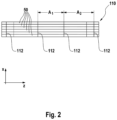
- Each glass body layer 110 has four spacer positions 112, which are arranged at a distance A. In the embodiment shown here, two different distances A1 and A2 are provided.
- a wrapping 120 made of a shrink film is arranged, which extends over an end section of the glass body layer 110 and thus over end sections of the glass body 50 and covers the end faces of the glass body bundle 100. Since the embodiment shown here involves glass tubes, the casing 120 also covers the tube openings, so that the interior of the glass tubes is protected from contamination.
- a top view of a glass body layer 110 is shown, which includes six glass bodies 50.
- a glass body layer 110 with only three glass bodies 50 is shown in perspective in order to explain the arrangement of a thread-like element 10. Only the sections of the glass body 50 are shown where, for example, a spacer position 112 is located.
- the distance between the glass bodies 50 is shown significantly larger and the thread-like element 10 is provided with arrows P in order to clarify the running direction of the thread-like element 10, which is in connection with the manufacturing process of the glass body layer 110 (see Figures 16 to 19 ) will be explained in more detail.
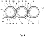
- FIG 4 is a top view of the in Figure 3 shown section of a vitreous body layer 110 can be seen.
- a single thread-like element 10 with the ends 11 and 12 wraps around all three glass bodies 50, whereby the thread-like element 10 does not have to rest against the outer surface of the glass bodies 50 everywhere. Whether the thread-like element 10 rests on the outer surface of the glass body 50 depends on the selected thread tension of the thread-like element 10 during the manufacturing process of the glass body layer 110. The distance between the adjacent glass bodies 50 can also be adjusted via the thread tension.
- center points MP of the glass body 50 are shown, which lie on a line L.
- the center lines ML of the glass bodies 50 lie in a common plane E, which intersects the outer surfaces of the glass bodies 50 in the so-called contact line 114.
- the glass bodies 50 arranged next to one another would contact each other at this contact line 114 if no spacers were provided.
- the thread-like element 10 wraps around the upper outer circumference of the glass bodies 50 and forms a loop 13 there, which merges into the thread section 14 in the area of the contact line 114, which forms the spacer between the glass bodies 50.
- each thread section 14 wraps around approximately 10% of the outer circumference of the glass body 50.
- the thread-like element 10 each has a loop 16, which is located with the first and second loop sections 17 and 18 under the respective glass bodies 50.
- the two loop sections 17 and 18 are connected to one another via a third loop section 19, which is essentially located in a lower wedge-shaped space 15.
- Two of the three loops 16 each wrap around a neighboring loop 16.
- the loop sections 17 and 18 of one loop 16 are passed through the neighboring loop 16. It is also possible to arrange the thread-like element 10 so that the loops 16 lie on the top of the glass body 50.
- the thread sections 14 form the spacers between adjacent glass bodies 50
- the loops 16, in particular the loop sections 17 and 18, are available as spacers between the glass bodies 50 of two glass body layers 110 lying one on top of the other in the ⁇ direction.
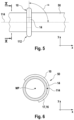
- Figure 5 shows the top view of a glass body section with a thread-like element 10, the thread section 14 forming an angle ⁇ of 90 ° with the z-axis and thus with the contact line 114.
- Figure 6 shows a section through the vitreous body 50 along the line XX in Figure 5 to illustrate the thread section 14 acting as a spacer.
- the in connection with the Figure 4 The mentioned ten percent coverage of the outer circumference of the glass body 50 means that the thread section 14 extends on both sides of the contact line 114 over approximately 5% of the outer circumference of the glass body 50. If adjacent glass bodies 50 slip in the ⁇ direction, the thread section 14 always prevents contact between the surfaces of the adjacent glass bodies 50.
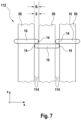
- the Figure 7 shows a top view of the vitreous body layer 110 Figure 3 , so that it can be seen that the distance B between adjacent glass bodies 50 corresponds to the thread thickness S of the thread sections 14.
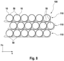
- FIG 8 the top view of the end face of a vitreous body bundle 100 is shown, which has three vitreous body layers 110 according to the Figures 3 to 7 having.
- the glass body layers 110 are arranged offset from one another, so that when the glass body layers 110 have assumed their final position, the closest packing of the glass bodies 50 is achieved.
- the vitreous body layers 110 have not yet reached their final position for a better representation of the thread courses. It can be seen that the loops 16 form spacers between glass bodies 50 lying one above the other.
- FIG. 9 are like in the Figure 3 the center points MP, the center lines ML, the line L, the plane E and the contact lines 114 are shown.
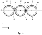
- Figure 10 is a top view of the in Figure 9 shown section of a vitreous body layer 110 can be seen.
- first thread-like element 20, which can also be referred to as the upper thread 20 wraps around the upper half of the outer circumference of the glass body 50 and forms an upper loop 25, while the second thread-like element 30, which can also be referred to as the lower thread 30, wraps around the lower half the outer circumference of the glass body 50 wraps around and forms a lower wrap 35.
- the ends 21, 23 of the upper thread 20 are connected to the ends 31, 33 of the lower thread 30, for example by welding or gluing.
- the thread sections 24 forming the spacers are located between the upper loops 25.
- the thread sections 34 forming the spacers are located between the lower loop 35.
- Each thread section 24, 34 rests both on the outer circumference of one glass body 50 and on the outer circumference of the adjacent glass body 50 .
- the thread sections 24, 34 are loops 27 which are hung one inside the other and form a loop 40.
- the thread sections 24, 34 are the spacers and are located with the loops 40 in the area of the contact line 114.
- the entanglement 40 is in Figure 11 shown enlarged.
- a modification of the tangle 40 is shown, referred to as a knotted tangle 40'.
- the thread section 24 is designed as a loop 26, with the thread section 24 crossing each other.
- the loop 27 of the thread section 34 is hooked into this loop 26 and when the loop 26 is closed, the thread section 34 is fixed in the loop 26.
- the Figure 13 shows a schematic top view of the vitreous body layer 110 Figure 9 , so that it can be seen that the distance B between the adjacent glass bodies is 50 due to the entanglement 40 can be larger than the thread thickness S of the thread sections 24,34.
- FIG 14 the end face of a vitreous body bundle 100 is shown, which has three vitreous body layers 110 stacked on top of one another in the Y direction according to FIG Figure 9 having.
- the glass body layers 110 are arranged offset from one another so that the closest packing is achieved.
- a packaging system 60 for producing glass body layers 110 and glass body bundles 100 is shown schematically.
- the glass bodies 50 are provided on an inclined plane 64 and taken over by a first conveyor belt 66 in a feed station 62.
- the individual glass bodies 50 are transferred to a second conveyor belt 70 and fed to a separation station 68.
- the isolated glass bodies 50 are fed with the conveyor belt 70 to a packing station 80, which has at least two wrapping stations 82.
- the wrapping stations 82 are arranged next to each other at a distance A which corresponds to the distance between the spacer positions 112 of the vitreous body layer 110, so that the wrapping process can be carried out in the spacer positions 112 of the vitreous body layer 110.
- the second conveyor belt 70 consists of several individual belts 71 arranged next to one another and operated synchronously, the number of which depends on the number of wrapping stations 82.
- three individual belts 71 are provided, which are arranged at a distance from one another.
- the space between the individual belts 71 is required for the needles 84 of the wrapping stations 82 to be pierced.
- the finished glass body layer 110 is then fed to a container 130 in a displacement station 95, in which the individual glass body layers 110 are stacked one on top of the other in the closest packing.
- a vitreous body bundle 100 in the container 130 which is transported away and in a wrapping station, not shown, is provided with a wrapping 120 by means of a shrink film at the ends 102, 104.
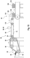
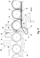
- such a wrapping station 82 according to a first embodiment is shown in a side view, which is preceded by the separating station 68.
- a separating tool 72 is provided, which is wedge-shaped and is inserted in the vertical direction between the glass bodies 50 arriving on the second conveyor belt 70 in order to separate the glass bodies 50.
- the isolated glass body 50 is then fixed on the second conveyor belt 70 by means of a hold-down device 83 and is wrapped in the wrapping station 82 with a thread-like element 10, which is fed from above to an eyelet 85 of a needle 84.
- the side view of an individual belt 71 of the second conveyor belt 70 can be seen.
- the needle 84 is located above the second conveyor belt 70 and is moved in a vertical direction.
- the needle 84 works together with a thread driver 86, which is arranged under the second conveyor belt 70.
- the thread driver 86 is a loop catcher 87, which captures the loop 16 of the thread-like element 10 extending through the space between two adjacent individual belts 71 of the second conveyor belt.
- the thread-like element 10 is guided through the existing loop 16 using the needle 84.
- the individual stages of the wrapping process are described in the Figures 17 to 19 explained in more detail.
- the method is characterized by a needle 84 moving up and down and a loop catcher 87 swinging back and forth.
- the wrapping process is comparable to the single-thread chain stitch process known from sewing machines.
- the needle 84 is lowered further and the loop catcher 87 releases the loop 16, as in Figure 18 can be seen, the needle 84 holds the loop 16 in place and stretches it until the needle 84 has entered the loop 16, which is held open.
- the loop catcher 87 is then retracted and releases the loop 16.
- the loop catcher 87 grasps the new loop 16, which is located in the previous loop 16 and ties it. The process then begins again in order to wrap around the subsequent glass body 50.
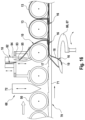
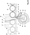
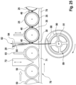
- a wrapping station 82 according to a second embodiment not according to the invention is shown in a side view, which is preceded by the separating station 68.
- a separating tool 72 is provided, which is wedge-shaped and is inserted in the vertical direction between the glass bodies 50 arriving on the second conveyor belt 70 in order to separate the glass bodies 50.
- the isolated glass body 50 is then fixed on the second conveyor belt 70 by means of a hold-down device 83 and wrapped in the wrapping station 82 with a first thread-like element 20 (upper thread) and a second thread-like element 30 (lower thread).
- the upper thread 20 is fed from above to an eyelet 85 of a needle 84, which is located above the second conveyor belt 70.
- the lower thread 30 is wound on a spool 89 and is fed to the glass bodies 50 from below through a gap between adjacent individual belts 71 of the second conveyor belt 70.
- the second conveyor belt 70 consists of two or more synchronously driven belt belts arranged in the direction of travel, which form the individual belts 71. These individual bands 71 are positioned in the axis of the glass bodies 50 so that the needles 84 can be positioned in the free spaces and are not hindered by the individual bands 71.
- the spool 89 is arranged in a spool housing 91, which is surrounded by an annular thread driver 86, which is also referred to as a ring gripper 88.
- the coil 89 and the ring gripper 88 rotate together in the direction of the arrow about a horizontal axis 90.
- the needle 84 is moved down into the area of the bobbin 89, whereby the upper thread 20 forms a loop 27, which is caught by the ring gripper 88 (see Fig. Fig. 21 , 22 ).
- the upper thread 20 is moved around Bobbin 89 is pulled around and the needle 84 is pulled back upwards, at the same time the lower thread 30 being inserted into the loop 27 of the upper thread 20 (see Fig. Fig. 23 ).
- the loop 27 of the upper thread 20 is then released by the ring gripper 88 (see Fig. Fig. 24 ). This creates the entanglement 40 (see Fig. Fig. 25 ).
- the process then begins again in order to wrap around the subsequent glass body 50.
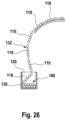
- FIG 26 the production of a vitreous body bundle 100 is shown.
- the individual vitreous body layers 110 are not separated from each other after the wrapping process has been carried out, as is the case in connection with Figure 15 was explained.
- a strip of layers 132 made of glass body layers 110 is fed to a U-shaped container 130, in which the strip of layers 132 is placed folded so that the individual glass body layers 110 lie on top of each other in the closest packing.
- the layer band 132 is separated between two glass body layers 110.
- the vitreous body bundle 100 is provided with a covering 120 from both ends and then removed from the container 130.
Landscapes
- Engineering & Computer Science (AREA)
- Mechanical Engineering (AREA)
- Packaging Frangible Articles (AREA)
- Buffer Packaging (AREA)
- Wrapping Of Specific Fragile Articles (AREA)
Claims (11)
- Couche de corps en verre (110) avec au moins deux corps en verre (50), qui s'étendent dans une direction z et sont disposés l'un à côté de l'autre dans une direction x,dans laquelle au moins deux positions d'élément d'écartement (112) espacées l'une de l'autre d'une distance A, dans lesquelles des éléments d'écartement sont disposés entre les corps en verre (50), sont prévues le long des corps en verre (50) dans la direction z,dans laquelle les éléments d'écartement sont des éléments en forme de fil (10) comprenant deux extrémités (11, 12), dans laquelle au moins un élément en forme de fil (10) est prévu dans chaque position d'élément d'écartement (112) et dans laquelle les deux extrémités (11, 12) du au moins un élément en forme de fil (10) ne sont pas reliées l'une à l'autre, caractérisée en ce que l'élément en forme de fil (10) présente une épaisseur de fil S avec 0,25 mm <= S <= 2,5 mm,que les deux extrémités (11, 12) du au moins un élément en forme de fil (10) pendent latéralement sur la couche de corps en verre (110),et que l'élément en forme de fil (10) présente dans la direction y au-dessous ou au-dessus de chaque corps en verre (50) de la couche de corps en verre (110) une boucle (16).
- Couche de corps en verre (110) selon la revendication 1, caractérisée en ce que l'élément en forme de fil (10) dans la position d'élément d'écartement (112) respective enlace respectivement au moins en partie tous les corps en verre (50) de la couche de corps en verre (110) et/ou que respectivement deux parties de fil (14) de l'élément ou des éléments en forme de fil (10) sont disposées dans chaque position d'élément d'écartement (112) entre deux corps en verre (50) voisins et/ou que les corps en verre (50) sont des tubes en verre ou des barres en verre.
- Couche de corps en verre (110) selon l'une quelconque des revendications précédentes, caractérisée en ce que l'élément en forme de fil (10) est constitué d'une matière plastique, dans laquelle de préférence la matière plastique présente du polypropylène (PP), de la cire de polyéthylène, ou du polyéthylène (PE), en particulier du polyéthylène haute densité (HDPE), du polyamide (PA), un copolymère styrène-acrylonitrile (SAN), du polyester, du polyéthylène téréphtalate (PET), du polybutylène téréphtalate (PBT), du polyuréthane (PU), un copolymère acrylonitrile-butadiène-styrène (ABS), du polyétheréthercétone (PEEK) et/ou du polycarbonate (PC) ou est constitué des polymères cités.
- Couche de corps en verre (110) selon l'une quelconque des revendications précédentes, caractérisée en ce que les positions d'élément d'écartement (112) sont prévues par intervalles A de 20 cm à 80 cm.
- Couche de corps en verre (110) selon l'une quelconque des revendications 2 à 4, caractérisée en ce que les deux parties de fil (14) sont les parties d'un élément en forme de fil (10), dans laquelle de manière particulièrement préférée les deux parties de fil (14) s'étendent selon un angle α avec 80 degrés ≤ α ≤ 100 degrés par rapport à l'axe z.
- Couche de corps en verre (110) selon la revendication 5, caractérisée en ce que chaque partie de fil (14) entoure au moins 5 % de la périphérie extérieure d'un corps en verre (50), et/ou que les parties de fil (14) sont disposées les unes à côté des autres dans la direction z et/ou que l'élément en forme de fil (10) enlace au moins 70 % de la périphérie extérieure des corps en verre (50).
- Paquet de corps en verre (100) avec au moins deux couches de corps en verre (110) selon l'une quelconque des revendications 1 à 6 disposées l'une sur l'autre dans la direction y, caractérisé en ce que les couches de corps en verre (110) sont disposées les unes au-dessus des autres de manière décalée.
- Paquet de corps en verre (100) selon la revendication 7, caractérisé en ce que les éléments en forme de fil (10) des couches de corps en verre (110) sont des éléments d'écartement entre les corps en verre (50) de couches de corps en verre (110) voisines et/ou que le paquet de corps en verre (100) présente au moins sur les deux extrémités (102, 104) du paquet de corps en verre (100) une enveloppe (120), dans lequel en particulier l'enveloppe (120) est constituée d'un film thermo-rétractable.
- Procédé d'emballage pour la fabrication d'une couche de corps en verre (110) avec au moins deux corps en verre (50) selon l'une quelconque des revendications 1 à 6 avec les étapes suivantes dans l'ordre suivant :a) la fourniture des corps en verre (50)b) l'amenée continue d'au moins deux corps en verre (50) et la séparation des corps en verre (50) dans un poste de séparation (68)c) l'amenée continue des corps en verre (50) séparés à un poste d'emballage (80) avec au moins deux postes d'enlacement (82) disposés dans des positions d'élément d'écartement (112) prédéfinies,d) l'amenée continue de respectivement un élément en forme de fil (10) à chaque poste d'enlacement (82)e) l'enlacement des corps en verre (50) sur les positions d'élément d'écartement (112) prédéfinies avec l'élément en forme de fil (10) au moyen d'un procédé d'enlacement,f) l'achèvement du processus d'enlacement etg) l'évacuation de la couche de corps en verre (110) dans lequell'élément en forme de fil (10) présente une épaisseur de fil S avec 0,25 mm <= S <= 2,5 mm et comprend deux extrémités (11, 12), les deux extrémités (11, 12) de l'élément en forme de fil (10) ne sont pas reliées l'une à l'autre et pendent latéralement sur la couche de corps en verre (110), et dans lequel un élément en forme de fil (10) est disposé dans chaque position d'élément d'écartement (112) et l'élément en forme de fil (10) présente dans la direction y au-dessous ou au-dessus de chaque corps en verre (50) de la couche de corps en verre (110) une boucle (16).
- Procédé selon la revendication 9, dans lequel dans l'étape e) le procédé d'enlacement dans chaque position d'élément d'écartement (112) entre les corps en verre (50) comprend la disposition de respectivement deux parties de fil (14) situées l'une à côté de l'autre.
- Procédé selon la revendication 9 ou 10, dans lequel entre l'étape f) et g) l'étape suivante est mise en oeuvre :
f1) le sectionnement de l'élément en forme de fil (10) après l'enlacement du dernier corps en verre (50) d'une couche de corps en verre (110) ou dans lequel entre l'étape f) et g) l'étape suivante est mise en oeuvre :
f2) la poursuite du procédé d'enlacement pour l'enlacement d'une autre couche de corps en verre (110) sans sectionnement préalable de l'élément en forme de fil (10) après l'enlacement du dernier corps en verre (50) d'une couche de corps en verre (110).
Applications Claiming Priority (1)
| Application Number | Priority Date | Filing Date | Title |
|---|---|---|---|
| DE102018221782.3A DE102018221782A1 (de) | 2018-12-14 | 2018-12-14 | Glaskörperlage, Glaskörperbündel sowie Packverfahren |
Publications (2)
| Publication Number | Publication Date |
|---|---|
| EP3666680A1 EP3666680A1 (fr) | 2020-06-17 |
| EP3666680B1 true EP3666680B1 (fr) | 2023-09-13 |
Family
ID=68887239
Family Applications (1)
| Application Number | Title | Priority Date | Filing Date |
|---|---|---|---|
| EP19215498.7A Active EP3666680B1 (fr) | 2018-12-14 | 2019-12-12 | Couche d'éléments en verre, paquet d'éléments en verre, et procédé d'emballage |
Country Status (5)
| Country | Link |
|---|---|
| US (1) | US11352197B2 (fr) |
| EP (1) | EP3666680B1 (fr) |
| JP (1) | JP7485508B2 (fr) |
| CN (1) | CN111319881B (fr) |
| DE (1) | DE102018221782A1 (fr) |
Families Citing this family (4)
| Publication number | Priority date | Publication date | Assignee | Title |
|---|---|---|---|---|
| DE102018221781A1 (de) | 2018-12-14 | 2020-06-18 | Schott Ag | Glaskörperlage, Glaskörperbündel sowie Herstellungsverfahren einer Glaskörperlage |
| JP2021138453A (ja) * | 2020-03-02 | 2021-09-16 | ショット アクチエンゲゼルシャフトSchott AG | 管状および/または棒状のガラス物品の束、その製造方法、ならびに該束を開梱する方法 |
| JP2021138454A (ja) * | 2020-03-02 | 2021-09-16 | ショット アクチエンゲゼルシャフトSchott AG | 管状および/または棒状のガラス物品の束、その製造方法、ならびに該束を開梱する方法 |
| CN115783525B (zh) * | 2022-11-18 | 2025-08-29 | 江苏苏钏科技有限公司 | 超薄玻璃装载治具 |
Citations (1)
| Publication number | Priority date | Publication date | Assignee | Title |
|---|---|---|---|---|
| US20140196402A1 (en) * | 2011-09-22 | 2014-07-17 | Lisec Austria Gmbh | Device for inserting distancing cords |
Family Cites Families (26)
| Publication number | Priority date | Publication date | Assignee | Title |
|---|---|---|---|---|
| DE224556C (fr) | ||||
| DD82301A (fr) | ||||
| DE82301C (fr) | ||||
| US2350752A (en) * | 1941-12-01 | 1944-06-06 | Electric Storage Battery Co | Plate for secondary or storage batteries |
| US3143266A (en) * | 1961-10-04 | 1964-08-04 | Imatake Midorl | Self-tightening article carrier |
| US3294225A (en) | 1965-04-26 | 1966-12-27 | Corning Glass Works | Combined shipping package and protective armor for glass pipe |
| US3373540A (en) * | 1965-07-13 | 1968-03-19 | Corning Glass Works | Method of bundling |
| US3611656A (en) | 1970-04-24 | 1971-10-12 | Container Corp | Method and apparatus for forming carriers for container groups |
| DE2729966C2 (de) | 1977-07-02 | 1985-10-03 | Schott-Ruhrglas GmbH, 8580 Bayreuth | Gebinde von Röhren aus sprödem Material |
| US4137821A (en) * | 1977-05-27 | 1979-02-06 | Tesseract Corporation | Article handling belt |
| US4385696A (en) * | 1981-08-21 | 1983-05-31 | Wayne H. Coloney Company, Inc. | Linked container article carrier |
| DE8317864U1 (de) | 1983-06-20 | 1984-03-08 | Georg J. Strasser Engineering + Konstruktion, 9215 Schönenberg | Rohrbuendel |
| DD224555A1 (de) | 1984-03-29 | 1985-07-10 | Jenaer Glaswerk Veb | Verfahren zum schrumpffolienverpacken von glasrohren oder glasstaeben |
| US4693167A (en) * | 1985-03-25 | 1987-09-15 | Howden Coloney, Inc. | Strap for linked container article carrier |
| DE3701556C1 (de) | 1987-01-21 | 1988-06-01 | Mannesmann Ag | Verfahren und Einrichtung zum Manipulieren von kleinkalibrigen Rohren sowie Fertigungseinrichtungen und eine Behandlungseinrichtung,insbesondere fuer Brems-,Kraftstoff- oder Hydraulikleitungen |
| US5294222A (en) | 1992-03-10 | 1994-03-15 | Mobil Oil Corporation | Method of preventing damage to pipe joints during shipment |
| DE4225876C2 (de) | 1992-08-05 | 2001-10-11 | Schott Rohrglas Gmbh | Packaufnahme und Verfahren sowie Vorrichtung zur Herstellung mindestens einer Packaufnahme für stabförmige Gegenstände |
| JPH09295686A (ja) | 1996-04-26 | 1997-11-18 | Nippon Electric Glass Co Ltd | ガラス管包装体 |
| US6915619B2 (en) | 2001-08-10 | 2005-07-12 | Baxa Corporation | Method for handling syringe bodies |
| DE20121582U1 (de) | 2001-08-24 | 2003-02-27 | Schott Glas, 55122 Mainz | Verpackung für Glasrohre |
| DE102005020892A1 (de) * | 2005-05-04 | 2006-11-09 | Saint-Gobain Isover G+H Ag | Verpackungseinheit für Rohrschalen |
| US8622440B2 (en) | 2010-10-05 | 2014-01-07 | Ideal Industries, Inc. | Knot tying device and cartridge system for providing tying filament thereto |
| CN106364794B (zh) * | 2010-11-30 | 2019-11-19 | 康宁股份有限公司 | 包装多个玻璃板的方法及玻璃板的包装 |
| JP2015054723A (ja) | 2013-09-13 | 2015-03-23 | 日本電気硝子株式会社 | ガラス管梱包体 |
| CN105501705B (zh) * | 2015-12-26 | 2018-01-26 | 宁波远志立方能源科技有限公司 | 一种用于玻璃运输的包装材料 |
| TWI720211B (zh) * | 2016-06-23 | 2021-03-01 | 美商康寧公司 | 用於包裝玻璃製品的方法及裝置 |
-
2018
- 2018-12-14 DE DE102018221782.3A patent/DE102018221782A1/de not_active Withdrawn
-
2019
- 2019-12-12 EP EP19215498.7A patent/EP3666680B1/fr active Active
- 2019-12-13 JP JP2019225425A patent/JP7485508B2/ja active Active
- 2019-12-16 CN CN201911294642.6A patent/CN111319881B/zh active Active
- 2019-12-16 US US16/715,872 patent/US11352197B2/en active Active
Patent Citations (1)
| Publication number | Priority date | Publication date | Assignee | Title |
|---|---|---|---|---|
| US20140196402A1 (en) * | 2011-09-22 | 2014-07-17 | Lisec Austria Gmbh | Device for inserting distancing cords |
Also Published As
| Publication number | Publication date |
|---|---|
| US20200189838A1 (en) | 2020-06-18 |
| EP3666680A1 (fr) | 2020-06-17 |
| US11352197B2 (en) | 2022-06-07 |
| CN111319881B (zh) | 2023-04-28 |
| JP2020097449A (ja) | 2020-06-25 |
| DE102018221782A1 (de) | 2020-06-18 |
| JP7485508B2 (ja) | 2024-05-16 |
| CN111319881A (zh) | 2020-06-23 |
Similar Documents
| Publication | Publication Date | Title |
|---|---|---|
| EP3666680A1 (fr) | Couche de corps vitré, faisceau de corps vitré ainsi que procédé d'emballage | |
| EP3666679A1 (fr) | Couche de corps vitré, ensemble de corps vitré et procédé de fabrication d'une couche de corps vitré | |
| DE3809635C2 (fr) | ||
| EP0149227B1 (fr) | Procédé de fabrication de paquets ou groupement d'articles emballés dans une feuille ainsi que dispositif pour la mise en oeuvre du procédé | |
| DE2843520A1 (de) | Kunststoffnetz, verfahren zum stabilisieren einer ladung auf einer palette mit hilfe eines solchen kunststoffnetzes sowie mit einem solchen kunststoffnetz umhuellte palettierte ladung | |
| WO2009068294A1 (fr) | Procédé de fabrication d'une unité d'emballage sans palette | |
| EP3774318A1 (fr) | Dispositif d'enroulement et système d'enroulement de rembourrage | |
| EP0141351B1 (fr) | Dispositif pour envelopper des paquets dans une feuille étirable | |
| DE102014001779A1 (de) | Vorrichtung zum Lagern von Filamentspulen | |
| EP4007722B1 (fr) | Dispositif et procédé de formation de paquets d'emballages individuels | |
| EP2248722A1 (fr) | Procédé et dispositif de fabrication d'une unité d'emballage sans palette et unité d'emballage sans palette | |
| DE69414778T2 (de) | Verpacken von Gegenständen | |
| DE69100691T2 (de) | Verfahren und Vorrichtung zum selbsttätigen Einwickeln von zylindrischen Gegenständen, insbesondere Kunststoffspülen. | |
| EP3738896A1 (fr) | Dispositif d'emballage pour articles ou groupes d'articles et procédé d'application d'un flan de carton sur un article ou un groupe d'articles | |
| DE29803049U1 (de) | Schlauchbeutelkette | |
| EP0672592B1 (fr) | Bande en matière plastique déformable élastiquement, procédé pour attacher des marchandises emballées et dispositif pour mettre en place et retirer cette bande | |
| DE4235007A1 (de) | Verfahren zum Wickeln und Vorrichtung zur Durchführung des Verfahrens | |
| DE19647543C2 (de) | Verpackungsfolie | |
| DE10217240A1 (de) | Verfahren und Vorrichtung zum Verpacken von Gegenständen | |
| WO2021032560A1 (fr) | Utilisation d'une unité d'emballage pour bandes de cerclage | |
| EP2876191B1 (fr) | Procédé et dispositif destinés au traitement de faisceaux de fibres | |
| DE102018119149A1 (de) | Verpackungsvorrichtung und Verfahren zur Herstellung von Stretchgebinden | |
| WO2025003268A1 (fr) | Système et procédé pour remplir des espaces vides dans des contenants de transport avec des unités de rembourrage en papier | |
| DE2827160A1 (de) | Rohrfoermige verpackung | |
| DE202023003088U1 (de) | Anordnung zum Füllen von Hohlräumen in Transportbehältern mit Polstereinheiten aus Papier |
Legal Events
| Date | Code | Title | Description |
|---|---|---|---|
| PUAI | Public reference made under article 153(3) epc to a published international application that has entered the european phase |
Free format text: ORIGINAL CODE: 0009012 |
|
| STAA | Information on the status of an ep patent application or granted ep patent |
Free format text: STATUS: THE APPLICATION HAS BEEN PUBLISHED |
|
| AK | Designated contracting states |
Kind code of ref document: A1 Designated state(s): AL AT BE BG CH CY CZ DE DK EE ES FI FR GB GR HR HU IE IS IT LI LT LU LV MC MK MT NL NO PL PT RO RS SE SI SK SM TR |
|
| AX | Request for extension of the european patent |
Extension state: BA ME |
|
| STAA | Information on the status of an ep patent application or granted ep patent |
Free format text: STATUS: REQUEST FOR EXAMINATION WAS MADE |
|
| 17P | Request for examination filed |
Effective date: 20200728 |
|
| RBV | Designated contracting states (corrected) |
Designated state(s): AL AT BE BG CH CY CZ DE DK EE ES FI FR GB GR HR HU IE IS IT LI LT LU LV MC MK MT NL NO PL PT RO RS SE SI SK SM TR |
|
| STAA | Information on the status of an ep patent application or granted ep patent |
Free format text: STATUS: EXAMINATION IS IN PROGRESS |
|
| 17Q | First examination report despatched |
Effective date: 20210326 |
|
| GRAP | Despatch of communication of intention to grant a patent |
Free format text: ORIGINAL CODE: EPIDOSNIGR1 |
|
| STAA | Information on the status of an ep patent application or granted ep patent |
Free format text: STATUS: GRANT OF PATENT IS INTENDED |
|
| INTG | Intention to grant announced |
Effective date: 20230525 |
|
| P01 | Opt-out of the competence of the unified patent court (upc) registered |
Effective date: 20230516 |
|
| GRAS | Grant fee paid |
Free format text: ORIGINAL CODE: EPIDOSNIGR3 |
|
| GRAA | (expected) grant |
Free format text: ORIGINAL CODE: 0009210 |
|
| STAA | Information on the status of an ep patent application or granted ep patent |
Free format text: STATUS: THE PATENT HAS BEEN GRANTED |
|
| AK | Designated contracting states |
Kind code of ref document: B1 Designated state(s): AL AT BE BG CH CY CZ DE DK EE ES FI FR GB GR HR HU IE IS IT LI LT LU LV MC MK MT NL NO PL PT RO RS SE SI SK SM TR |
|
| REG | Reference to a national code |
Ref country code: CH Ref legal event code: EP |
|
| REG | Reference to a national code |
Ref country code: DE Ref legal event code: R096 Ref document number: 502019009330 Country of ref document: DE |
|
| REG | Reference to a national code |
Ref country code: IE Ref legal event code: FG4D Free format text: LANGUAGE OF EP DOCUMENT: GERMAN |
|
| REG | Reference to a national code |
Ref country code: LT Ref legal event code: MG9D |
|
| REG | Reference to a national code |
Ref country code: NL Ref legal event code: MP Effective date: 20230913 |
|
| PG25 | Lapsed in a contracting state [announced via postgrant information from national office to epo] |
Ref country code: GR Free format text: LAPSE BECAUSE OF FAILURE TO SUBMIT A TRANSLATION OF THE DESCRIPTION OR TO PAY THE FEE WITHIN THE PRESCRIBED TIME-LIMIT Effective date: 20231214 |
|
| PG25 | Lapsed in a contracting state [announced via postgrant information from national office to epo] |
Ref country code: SE Free format text: LAPSE BECAUSE OF FAILURE TO SUBMIT A TRANSLATION OF THE DESCRIPTION OR TO PAY THE FEE WITHIN THE PRESCRIBED TIME-LIMIT Effective date: 20230913 Ref country code: RS Free format text: LAPSE BECAUSE OF FAILURE TO SUBMIT A TRANSLATION OF THE DESCRIPTION OR TO PAY THE FEE WITHIN THE PRESCRIBED TIME-LIMIT Effective date: 20230913 Ref country code: NO Free format text: LAPSE BECAUSE OF FAILURE TO SUBMIT A TRANSLATION OF THE DESCRIPTION OR TO PAY THE FEE WITHIN THE PRESCRIBED TIME-LIMIT Effective date: 20231213 Ref country code: LV Free format text: LAPSE BECAUSE OF FAILURE TO SUBMIT A TRANSLATION OF THE DESCRIPTION OR TO PAY THE FEE WITHIN THE PRESCRIBED TIME-LIMIT Effective date: 20230913 Ref country code: LT Free format text: LAPSE BECAUSE OF FAILURE TO SUBMIT A TRANSLATION OF THE DESCRIPTION OR TO PAY THE FEE WITHIN THE PRESCRIBED TIME-LIMIT Effective date: 20230913 Ref country code: HR Free format text: LAPSE BECAUSE OF FAILURE TO SUBMIT A TRANSLATION OF THE DESCRIPTION OR TO PAY THE FEE WITHIN THE PRESCRIBED TIME-LIMIT Effective date: 20230913 Ref country code: GR Free format text: LAPSE BECAUSE OF FAILURE TO SUBMIT A TRANSLATION OF THE DESCRIPTION OR TO PAY THE FEE WITHIN THE PRESCRIBED TIME-LIMIT Effective date: 20231214 Ref country code: FI Free format text: LAPSE BECAUSE OF FAILURE TO SUBMIT A TRANSLATION OF THE DESCRIPTION OR TO PAY THE FEE WITHIN THE PRESCRIBED TIME-LIMIT Effective date: 20230913 |
|
| PG25 | Lapsed in a contracting state [announced via postgrant information from national office to epo] |
Ref country code: NL Free format text: LAPSE BECAUSE OF FAILURE TO SUBMIT A TRANSLATION OF THE DESCRIPTION OR TO PAY THE FEE WITHIN THE PRESCRIBED TIME-LIMIT Effective date: 20230913 |
|
| PG25 | Lapsed in a contracting state [announced via postgrant information from national office to epo] |
Ref country code: IS Free format text: LAPSE BECAUSE OF FAILURE TO SUBMIT A TRANSLATION OF THE DESCRIPTION OR TO PAY THE FEE WITHIN THE PRESCRIBED TIME-LIMIT Effective date: 20240113 |
|
| PG25 | Lapsed in a contracting state [announced via postgrant information from national office to epo] |
Ref country code: ES Free format text: LAPSE BECAUSE OF FAILURE TO SUBMIT A TRANSLATION OF THE DESCRIPTION OR TO PAY THE FEE WITHIN THE PRESCRIBED TIME-LIMIT Effective date: 20230913 |
|
| PG25 | Lapsed in a contracting state [announced via postgrant information from national office to epo] |
Ref country code: SM Free format text: LAPSE BECAUSE OF FAILURE TO SUBMIT A TRANSLATION OF THE DESCRIPTION OR TO PAY THE FEE WITHIN THE PRESCRIBED TIME-LIMIT Effective date: 20230913 Ref country code: RO Free format text: LAPSE BECAUSE OF FAILURE TO SUBMIT A TRANSLATION OF THE DESCRIPTION OR TO PAY THE FEE WITHIN THE PRESCRIBED TIME-LIMIT Effective date: 20230913 Ref country code: IS Free format text: LAPSE BECAUSE OF FAILURE TO SUBMIT A TRANSLATION OF THE DESCRIPTION OR TO PAY THE FEE WITHIN THE PRESCRIBED TIME-LIMIT Effective date: 20240113 Ref country code: ES Free format text: LAPSE BECAUSE OF FAILURE TO SUBMIT A TRANSLATION OF THE DESCRIPTION OR TO PAY THE FEE WITHIN THE PRESCRIBED TIME-LIMIT Effective date: 20230913 Ref country code: EE Free format text: LAPSE BECAUSE OF FAILURE TO SUBMIT A TRANSLATION OF THE DESCRIPTION OR TO PAY THE FEE WITHIN THE PRESCRIBED TIME-LIMIT Effective date: 20230913 Ref country code: CZ Free format text: LAPSE BECAUSE OF FAILURE TO SUBMIT A TRANSLATION OF THE DESCRIPTION OR TO PAY THE FEE WITHIN THE PRESCRIBED TIME-LIMIT Effective date: 20230913 Ref country code: SK Free format text: LAPSE BECAUSE OF FAILURE TO SUBMIT A TRANSLATION OF THE DESCRIPTION OR TO PAY THE FEE WITHIN THE PRESCRIBED TIME-LIMIT Effective date: 20230913 Ref country code: PT Free format text: LAPSE BECAUSE OF FAILURE TO SUBMIT A TRANSLATION OF THE DESCRIPTION OR TO PAY THE FEE WITHIN THE PRESCRIBED TIME-LIMIT Effective date: 20240115 |
|
| PG25 | Lapsed in a contracting state [announced via postgrant information from national office to epo] |
Ref country code: PL Free format text: LAPSE BECAUSE OF FAILURE TO SUBMIT A TRANSLATION OF THE DESCRIPTION OR TO PAY THE FEE WITHIN THE PRESCRIBED TIME-LIMIT Effective date: 20230913 |
|
| REG | Reference to a national code |
Ref country code: DE Ref legal event code: R097 Ref document number: 502019009330 Country of ref document: DE |
|
| PG25 | Lapsed in a contracting state [announced via postgrant information from national office to epo] |
Ref country code: DK Free format text: LAPSE BECAUSE OF FAILURE TO SUBMIT A TRANSLATION OF THE DESCRIPTION OR TO PAY THE FEE WITHIN THE PRESCRIBED TIME-LIMIT Effective date: 20230913 |
|
| PLBE | No opposition filed within time limit |
Free format text: ORIGINAL CODE: 0009261 |
|
| STAA | Information on the status of an ep patent application or granted ep patent |
Free format text: STATUS: NO OPPOSITION FILED WITHIN TIME LIMIT |
|
| PG25 | Lapsed in a contracting state [announced via postgrant information from national office to epo] |
Ref country code: DK Free format text: LAPSE BECAUSE OF FAILURE TO SUBMIT A TRANSLATION OF THE DESCRIPTION OR TO PAY THE FEE WITHIN THE PRESCRIBED TIME-LIMIT Effective date: 20230913 |
|
| REG | Reference to a national code |
Ref country code: CH Ref legal event code: PL |
|
| 26N | No opposition filed |
Effective date: 20240614 |
|
| PG25 | Lapsed in a contracting state [announced via postgrant information from national office to epo] |
Ref country code: LU Free format text: LAPSE BECAUSE OF NON-PAYMENT OF DUE FEES Effective date: 20231212 |
|
| PG25 | Lapsed in a contracting state [announced via postgrant information from national office to epo] |
Ref country code: MC Free format text: LAPSE BECAUSE OF FAILURE TO SUBMIT A TRANSLATION OF THE DESCRIPTION OR TO PAY THE FEE WITHIN THE PRESCRIBED TIME-LIMIT Effective date: 20230913 |
|
| GBPC | Gb: european patent ceased through non-payment of renewal fee |
Effective date: 20231213 |
|
| REG | Reference to a national code |
Ref country code: BE Ref legal event code: MM Effective date: 20231231 |
|
| PG25 | Lapsed in a contracting state [announced via postgrant information from national office to epo] |
Ref country code: MC Free format text: LAPSE BECAUSE OF FAILURE TO SUBMIT A TRANSLATION OF THE DESCRIPTION OR TO PAY THE FEE WITHIN THE PRESCRIBED TIME-LIMIT Effective date: 20230913 Ref country code: LU Free format text: LAPSE BECAUSE OF NON-PAYMENT OF DUE FEES Effective date: 20231212 |
|
| REG | Reference to a national code |
Ref country code: IE Ref legal event code: MM4A |
|
| PG25 | Lapsed in a contracting state [announced via postgrant information from national office to epo] |
Ref country code: IE Free format text: LAPSE BECAUSE OF NON-PAYMENT OF DUE FEES Effective date: 20231212 |
|
| PG25 | Lapsed in a contracting state [announced via postgrant information from national office to epo] |
Ref country code: GB Free format text: LAPSE BECAUSE OF NON-PAYMENT OF DUE FEES Effective date: 20231213 |
|
| PG25 | Lapsed in a contracting state [announced via postgrant information from national office to epo] |
Ref country code: BE Free format text: LAPSE BECAUSE OF NON-PAYMENT OF DUE FEES Effective date: 20231231 |
|
| PG25 | Lapsed in a contracting state [announced via postgrant information from national office to epo] |
Ref country code: CH Free format text: LAPSE BECAUSE OF NON-PAYMENT OF DUE FEES Effective date: 20231231 |
|
| PG25 | Lapsed in a contracting state [announced via postgrant information from national office to epo] |
Ref country code: SI Free format text: LAPSE BECAUSE OF FAILURE TO SUBMIT A TRANSLATION OF THE DESCRIPTION OR TO PAY THE FEE WITHIN THE PRESCRIBED TIME-LIMIT Effective date: 20230913 |
|
| PG25 | Lapsed in a contracting state [announced via postgrant information from national office to epo] |
Ref country code: SI Free format text: LAPSE BECAUSE OF FAILURE TO SUBMIT A TRANSLATION OF THE DESCRIPTION OR TO PAY THE FEE WITHIN THE PRESCRIBED TIME-LIMIT Effective date: 20230913 Ref country code: IE Free format text: LAPSE BECAUSE OF NON-PAYMENT OF DUE FEES Effective date: 20231212 Ref country code: GB Free format text: LAPSE BECAUSE OF NON-PAYMENT OF DUE FEES Effective date: 20231213 Ref country code: CH Free format text: LAPSE BECAUSE OF NON-PAYMENT OF DUE FEES Effective date: 20231231 Ref country code: BE Free format text: LAPSE BECAUSE OF NON-PAYMENT OF DUE FEES Effective date: 20231231 |
|
| PG25 | Lapsed in a contracting state [announced via postgrant information from national office to epo] |
Ref country code: BG Free format text: LAPSE BECAUSE OF FAILURE TO SUBMIT A TRANSLATION OF THE DESCRIPTION OR TO PAY THE FEE WITHIN THE PRESCRIBED TIME-LIMIT Effective date: 20230913 |
|
| PG25 | Lapsed in a contracting state [announced via postgrant information from national office to epo] |
Ref country code: BG Free format text: LAPSE BECAUSE OF FAILURE TO SUBMIT A TRANSLATION OF THE DESCRIPTION OR TO PAY THE FEE WITHIN THE PRESCRIBED TIME-LIMIT Effective date: 20230913 |
|
| PG25 | Lapsed in a contracting state [announced via postgrant information from national office to epo] |
Ref country code: CY Free format text: LAPSE BECAUSE OF FAILURE TO SUBMIT A TRANSLATION OF THE DESCRIPTION OR TO PAY THE FEE WITHIN THE PRESCRIBED TIME-LIMIT; INVALID AB INITIO Effective date: 20191212 |
|
| PG25 | Lapsed in a contracting state [announced via postgrant information from national office to epo] |
Ref country code: HU Free format text: LAPSE BECAUSE OF FAILURE TO SUBMIT A TRANSLATION OF THE DESCRIPTION OR TO PAY THE FEE WITHIN THE PRESCRIBED TIME-LIMIT; INVALID AB INITIO Effective date: 20191212 |
|
| PG25 | Lapsed in a contracting state [announced via postgrant information from national office to epo] |
Ref country code: TR Free format text: LAPSE BECAUSE OF FAILURE TO SUBMIT A TRANSLATION OF THE DESCRIPTION OR TO PAY THE FEE WITHIN THE PRESCRIBED TIME-LIMIT Effective date: 20230913 |
|
| PGFP | Annual fee paid to national office [announced via postgrant information from national office to epo] |
Ref country code: DE Payment date: 20251211 Year of fee payment: 7 |
|
| PGFP | Annual fee paid to national office [announced via postgrant information from national office to epo] |
Ref country code: IT Payment date: 20251223 Year of fee payment: 7 |
|
| PGFP | Annual fee paid to national office [announced via postgrant information from national office to epo] |
Ref country code: FR Payment date: 20251229 Year of fee payment: 7 |
|
| REG | Reference to a national code |
Ref country code: AT Ref legal event code: MM01 Ref document number: 1611093 Country of ref document: AT Kind code of ref document: T Effective date: 20241212 |
|
| PG25 | Lapsed in a contracting state [announced via postgrant information from national office to epo] |
Ref country code: AT Free format text: LAPSE BECAUSE OF NON-PAYMENT OF DUE FEES Effective date: 20241212 |
|
| PGFP | Annual fee paid to national office [announced via postgrant information from national office to epo] |
Ref country code: AT Payment date: 20260410 Year of fee payment: 5 |