EP3666687B1 - Ausgabebehälter, kundenspezifisches ausgabesystem mit ausgabebehälter, und verfahren zur steuerung der ausgabe in einem ausgabebehälter - Google Patents
Ausgabebehälter, kundenspezifisches ausgabesystem mit ausgabebehälter, und verfahren zur steuerung der ausgabe in einem ausgabebehälter Download PDFInfo
- Publication number
- EP3666687B1 EP3666687B1 EP18845014.2A EP18845014A EP3666687B1 EP 3666687 B1 EP3666687 B1 EP 3666687B1 EP 18845014 A EP18845014 A EP 18845014A EP 3666687 B1 EP3666687 B1 EP 3666687B1
- Authority
- EP
- European Patent Office
- Prior art keywords
- discharge
- contents
- piston
- container
- inlet holes
- Prior art date
- Legal status (The legal status is an assumption and is not a legal conclusion. Google has not performed a legal analysis and makes no representation as to the accuracy of the status listed.)
- Active
Links
Images





Classifications
-
- B—PERFORMING OPERATIONS; TRANSPORTING
- B65—CONVEYING; PACKING; STORING; HANDLING THIN OR FILAMENTARY MATERIAL
- B65D—CONTAINERS FOR STORAGE OR TRANSPORT OF ARTICLES OR MATERIALS, e.g. BAGS, BARRELS, BOTTLES, BOXES, CANS, CARTONS, CRATES, DRUMS, JARS, TANKS, HOPPERS, FORWARDING CONTAINERS; ACCESSORIES, CLOSURES, OR FITTINGS THEREFOR; PACKAGING ELEMENTS; PACKAGES
- B65D83/00—Containers or packages with special means for dispensing contents
- B65D83/14—Containers for dispensing liquid or semi-liquid contents by internal gaseous pressure, i.e. aerosol containers comprising propellant
- B65D83/60—Containers for dispensing liquid or semi-liquid contents by internal gaseous pressure, i.e. aerosol containers comprising propellant with contents and propellant separated
- B65D83/64—Containers for dispensing liquid or semi-liquid contents by internal gaseous pressure, i.e. aerosol containers comprising propellant with contents and propellant separated by pistons
-
- A—HUMAN NECESSITIES
- A45—HAND OR TRAVELLING ARTICLES
- A45D—HAIRDRESSING OR SHAVING EQUIPMENT; EQUIPMENT FOR COSMETICS OR COSMETIC TREATMENTS, e.g. FOR MANICURING OR PEDICURING
- A45D34/00—Containers or accessories specially adapted for handling liquid toiletry or cosmetic substances, e.g. perfumes
- A45D34/04—Appliances specially adapted for applying liquid, e.g. using roller or ball
-
- B—PERFORMING OPERATIONS; TRANSPORTING
- B05—SPRAYING OR ATOMISING IN GENERAL; APPLYING FLUENT MATERIALS TO SURFACES, IN GENERAL
- B05B—SPRAYING APPARATUS; ATOMISING APPARATUS; NOZZLES
- B05B12/00—Arrangements for controlling delivery; Arrangements for controlling the spray area
- B05B12/14—Arrangements for controlling delivery; Arrangements for controlling the spray area for supplying a selected one of a plurality of liquids or other fluent materials or several in selected proportions to a spray apparatus, e.g. to a single spray outlet
- B05B12/1409—Arrangements for controlling delivery; Arrangements for controlling the spray area for supplying a selected one of a plurality of liquids or other fluent materials or several in selected proportions to a spray apparatus, e.g. to a single spray outlet the selection means being part of the discharge apparatus, e.g. part of the spray gun
-
- A—HUMAN NECESSITIES
- A45—HAND OR TRAVELLING ARTICLES
- A45D—HAIRDRESSING OR SHAVING EQUIPMENT; EQUIPMENT FOR COSMETICS OR COSMETIC TREATMENTS, e.g. FOR MANICURING OR PEDICURING
- A45D34/00—Containers or accessories specially adapted for handling liquid toiletry or cosmetic substances, e.g. perfumes
-
- A—HUMAN NECESSITIES
- A45—HAND OR TRAVELLING ARTICLES
- A45D—HAIRDRESSING OR SHAVING EQUIPMENT; EQUIPMENT FOR COSMETICS OR COSMETIC TREATMENTS, e.g. FOR MANICURING OR PEDICURING
- A45D34/00—Containers or accessories specially adapted for handling liquid toiletry or cosmetic substances, e.g. perfumes
- A45D34/06—Containers or accessories specially adapted for handling liquid toiletry or cosmetic substances, e.g. perfumes in combination with other toiletry or cosmetic articles
-
- B—PERFORMING OPERATIONS; TRANSPORTING
- B01—PHYSICAL OR CHEMICAL PROCESSES OR APPARATUS IN GENERAL
- B01F—MIXING, e.g. DISSOLVING, EMULSIFYING OR DISPERSING
- B01F33/00—Other mixers; Mixing plants; Combinations of mixers
- B01F33/50—Movable or transportable mixing devices or plants
- B01F33/501—Movable mixing devices, i.e. readily shifted or displaced from one place to another, e.g. portable during use
- B01F33/5011—Movable mixing devices, i.e. readily shifted or displaced from one place to another, e.g. portable during use portable during use, e.g. hand-held
-
- B—PERFORMING OPERATIONS; TRANSPORTING
- B01—PHYSICAL OR CHEMICAL PROCESSES OR APPARATUS IN GENERAL
- B01F—MIXING, e.g. DISSOLVING, EMULSIFYING OR DISPERSING
- B01F33/00—Other mixers; Mixing plants; Combinations of mixers
- B01F33/80—Mixing plants; Combinations of mixers
- B01F33/84—Mixing plants with mixing receptacles receiving material dispensed from several component receptacles, e.g. paint tins
-
- B—PERFORMING OPERATIONS; TRANSPORTING
- B01—PHYSICAL OR CHEMICAL PROCESSES OR APPARATUS IN GENERAL
- B01F—MIXING, e.g. DISSOLVING, EMULSIFYING OR DISPERSING
- B01F35/00—Accessories for mixers; Auxiliary operations or auxiliary devices; Parts or details of general application
- B01F35/75—Discharge mechanisms
- B01F35/754—Discharge mechanisms characterised by the means for discharging the components from the mixer
- B01F35/75425—Discharge mechanisms characterised by the means for discharging the components from the mixer using pistons or plungers
-
- B—PERFORMING OPERATIONS; TRANSPORTING
- B05—SPRAYING OR ATOMISING IN GENERAL; APPLYING FLUENT MATERIALS TO SURFACES, IN GENERAL
- B05B—SPRAYING APPARATUS; ATOMISING APPARATUS; NOZZLES
- B05B11/00—Single-unit hand-held apparatus in which flow of contents is produced by the muscular force of the operator at the moment of use
- B05B11/01—Single-unit hand-held apparatus in which flow of contents is produced by the muscular force of the operator at the moment of use characterised by the means producing the flow
- B05B11/10—Pump arrangements for transferring the contents from the container to a pump chamber by a sucking effect and forcing the contents out through the dispensing nozzle
- B05B11/1081—Arrangements for pumping several liquids or other fluent materials from several containers, e.g. for mixing them at the moment of pumping
- B05B11/1083—Arrangements for pumping several liquids or other fluent materials from several containers, e.g. for mixing them at the moment of pumping in adjustable proportion
-
- B—PERFORMING OPERATIONS; TRANSPORTING
- B05—SPRAYING OR ATOMISING IN GENERAL; APPLYING FLUENT MATERIALS TO SURFACES, IN GENERAL
- B05B—SPRAYING APPARATUS; ATOMISING APPARATUS; NOZZLES
- B05B12/00—Arrangements for controlling delivery; Arrangements for controlling the spray area
- B05B12/14—Arrangements for controlling delivery; Arrangements for controlling the spray area for supplying a selected one of a plurality of liquids or other fluent materials or several in selected proportions to a spray apparatus, e.g. to a single spray outlet
- B05B12/1472—Arrangements for controlling delivery; Arrangements for controlling the spray area for supplying a selected one of a plurality of liquids or other fluent materials or several in selected proportions to a spray apparatus, e.g. to a single spray outlet separate supply lines supplying different materials to separate outlets of the spraying apparatus
-
- B—PERFORMING OPERATIONS; TRANSPORTING
- B05—SPRAYING OR ATOMISING IN GENERAL; APPLYING FLUENT MATERIALS TO SURFACES, IN GENERAL
- B05C—APPARATUS FOR APPLYING FLUENT MATERIALS TO SURFACES, IN GENERAL
- B05C17/00—Hand tools or apparatus using hand held tools, for applying liquids or other fluent materials to, for spreading applied liquids or other fluent materials on, or for partially removing applied liquids or other fluent materials from, surfaces
- B05C17/005—Hand tools or apparatus using hand held tools, for applying liquids or other fluent materials to, for spreading applied liquids or other fluent materials on, or for partially removing applied liquids or other fluent materials from, surfaces for discharging material from a reservoir or container located in or on the hand tool through an outlet orifice by pressure without using surface contacting members like pads or brushes
- B05C17/00553—Hand tools or apparatus using hand held tools, for applying liquids or other fluent materials to, for spreading applied liquids or other fluent materials on, or for partially removing applied liquids or other fluent materials from, surfaces for discharging material from a reservoir or container located in or on the hand tool through an outlet orifice by pressure without using surface contacting members like pads or brushes with means allowing the stock of material to consist of at least two different components
-
- B—PERFORMING OPERATIONS; TRANSPORTING
- B05—SPRAYING OR ATOMISING IN GENERAL; APPLYING FLUENT MATERIALS TO SURFACES, IN GENERAL
- B05C—APPARATUS FOR APPLYING FLUENT MATERIALS TO SURFACES, IN GENERAL
- B05C17/00—Hand tools or apparatus using hand held tools, for applying liquids or other fluent materials to, for spreading applied liquids or other fluent materials on, or for partially removing applied liquids or other fluent materials from, surfaces
- B05C17/005—Hand tools or apparatus using hand held tools, for applying liquids or other fluent materials to, for spreading applied liquids or other fluent materials on, or for partially removing applied liquids or other fluent materials from, surfaces for discharging material from a reservoir or container located in or on the hand tool through an outlet orifice by pressure without using surface contacting members like pads or brushes
- B05C17/00553—Hand tools or apparatus using hand held tools, for applying liquids or other fluent materials to, for spreading applied liquids or other fluent materials on, or for partially removing applied liquids or other fluent materials from, surfaces for discharging material from a reservoir or container located in or on the hand tool through an outlet orifice by pressure without using surface contacting members like pads or brushes with means allowing the stock of material to consist of at least two different components
- B05C17/00556—Hand tools or apparatus using hand held tools, for applying liquids or other fluent materials to, for spreading applied liquids or other fluent materials on, or for partially removing applied liquids or other fluent materials from, surfaces for discharging material from a reservoir or container located in or on the hand tool through an outlet orifice by pressure without using surface contacting members like pads or brushes with means allowing the stock of material to consist of at least two different components with means for adjusting the proportions of the components
-
- B—PERFORMING OPERATIONS; TRANSPORTING
- B05—SPRAYING OR ATOMISING IN GENERAL; APPLYING FLUENT MATERIALS TO SURFACES, IN GENERAL
- B05C—APPARATUS FOR APPLYING FLUENT MATERIALS TO SURFACES, IN GENERAL
- B05C17/00—Hand tools or apparatus using hand held tools, for applying liquids or other fluent materials to, for spreading applied liquids or other fluent materials on, or for partially removing applied liquids or other fluent materials from, surfaces
- B05C17/005—Hand tools or apparatus using hand held tools, for applying liquids or other fluent materials to, for spreading applied liquids or other fluent materials on, or for partially removing applied liquids or other fluent materials from, surfaces for discharging material from a reservoir or container located in or on the hand tool through an outlet orifice by pressure without using surface contacting members like pads or brushes
- B05C17/00569—Hand tools or apparatus using hand held tools, for applying liquids or other fluent materials to, for spreading applied liquids or other fluent materials on, or for partially removing applied liquids or other fluent materials from, surfaces for discharging material from a reservoir or container located in or on the hand tool through an outlet orifice by pressure without using surface contacting members like pads or brushes with a pump in the hand tool
-
- B—PERFORMING OPERATIONS; TRANSPORTING
- B65—CONVEYING; PACKING; STORING; HANDLING THIN OR FILAMENTARY MATERIAL
- B65D—CONTAINERS FOR STORAGE OR TRANSPORT OF ARTICLES OR MATERIALS, e.g. BAGS, BARRELS, BOTTLES, BOXES, CANS, CARTONS, CRATES, DRUMS, JARS, TANKS, HOPPERS, FORWARDING CONTAINERS; ACCESSORIES, CLOSURES, OR FITTINGS THEREFOR; PACKAGING ELEMENTS; PACKAGES
- B65D81/00—Containers, packaging elements, or packages, for contents presenting particular transport or storage problems, or adapted to be used for non-packaging purposes after removal of contents
- B65D81/32—Containers, packaging elements, or packages, for contents presenting particular transport or storage problems, or adapted to be used for non-packaging purposes after removal of contents for packaging two or more different materials which must be maintained separate prior to use in admixture
- B65D81/3216—Rigid containers disposed one within the other
- B65D81/3227—Rigid containers disposed one within the other arranged parallel or concentrically and permitting simultaneous dispensing of the two materials without prior mixing
-
- B—PERFORMING OPERATIONS; TRANSPORTING
- B65—CONVEYING; PACKING; STORING; HANDLING THIN OR FILAMENTARY MATERIAL
- B65D—CONTAINERS FOR STORAGE OR TRANSPORT OF ARTICLES OR MATERIALS, e.g. BAGS, BARRELS, BOTTLES, BOXES, CANS, CARTONS, CRATES, DRUMS, JARS, TANKS, HOPPERS, FORWARDING CONTAINERS; ACCESSORIES, CLOSURES, OR FITTINGS THEREFOR; PACKAGING ELEMENTS; PACKAGES
- B65D81/00—Containers, packaging elements, or packages, for contents presenting particular transport or storage problems, or adapted to be used for non-packaging purposes after removal of contents
- B65D81/32—Containers, packaging elements, or packages, for contents presenting particular transport or storage problems, or adapted to be used for non-packaging purposes after removal of contents for packaging two or more different materials which must be maintained separate prior to use in admixture
- B65D81/3283—Cylindrical or polygonal containers, e.g. bottles, with two or more substantially axially offset, side-by-side compartments for simultaneous dispensing
- B65D81/3288—Cylindrical or polygonal containers, e.g. bottles, with two or more substantially axially offset, side-by-side compartments for simultaneous dispensing composed of two or more separate containers joined to each other
-
- B—PERFORMING OPERATIONS; TRANSPORTING
- B65—CONVEYING; PACKING; STORING; HANDLING THIN OR FILAMENTARY MATERIAL
- B65D—CONTAINERS FOR STORAGE OR TRANSPORT OF ARTICLES OR MATERIALS, e.g. BAGS, BARRELS, BOTTLES, BOXES, CANS, CARTONS, CRATES, DRUMS, JARS, TANKS, HOPPERS, FORWARDING CONTAINERS; ACCESSORIES, CLOSURES, OR FITTINGS THEREFOR; PACKAGING ELEMENTS; PACKAGES
- B65D83/00—Containers or packages with special means for dispensing contents
- B65D83/14—Containers for dispensing liquid or semi-liquid contents by internal gaseous pressure, i.e. aerosol containers comprising propellant
- B65D83/68—Dispensing two or more contents
- B65D83/682—Dispensing two or more contents initially separated and subsequently mixed
-
- A—HUMAN NECESSITIES
- A45—HAND OR TRAVELLING ARTICLES
- A45D—HAIRDRESSING OR SHAVING EQUIPMENT; EQUIPMENT FOR COSMETICS OR COSMETIC TREATMENTS, e.g. FOR MANICURING OR PEDICURING
- A45D34/00—Containers or accessories specially adapted for handling liquid toiletry or cosmetic substances, e.g. perfumes
- A45D2034/002—Accessories
-
- A—HUMAN NECESSITIES
- A45—HAND OR TRAVELLING ARTICLES
- A45D—HAIRDRESSING OR SHAVING EQUIPMENT; EQUIPMENT FOR COSMETICS OR COSMETIC TREATMENTS, e.g. FOR MANICURING OR PEDICURING
- A45D44/00—Other cosmetic or toiletry articles, e.g. for hairdressers' rooms
- A45D2044/007—Devices for determining the condition of hair or skin or for selecting the appropriate cosmetic or hair treatment
-
- A—HUMAN NECESSITIES
- A45—HAND OR TRAVELLING ARTICLES
- A45D—HAIRDRESSING OR SHAVING EQUIPMENT; EQUIPMENT FOR COSMETICS OR COSMETIC TREATMENTS, e.g. FOR MANICURING OR PEDICURING
- A45D2200/00—Details not otherwise provided for in A45D
- A45D2200/05—Details of containers
- A45D2200/054—Means for supplying liquid to the outlet of the container
- A45D2200/055—Piston or plunger for supplying the liquid to the applicator
-
- A—HUMAN NECESSITIES
- A45—HAND OR TRAVELLING ARTICLES
- A45D—HAIRDRESSING OR SHAVING EQUIPMENT; EQUIPMENT FOR COSMETICS OR COSMETIC TREATMENTS, e.g. FOR MANICURING OR PEDICURING
- A45D2200/00—Details not otherwise provided for in A45D
- A45D2200/05—Details of containers
- A45D2200/058—Means for mixing different substances prior to application
-
- B—PERFORMING OPERATIONS; TRANSPORTING
- B05—SPRAYING OR ATOMISING IN GENERAL; APPLYING FLUENT MATERIALS TO SURFACES, IN GENERAL
- B05B—SPRAYING APPARATUS; ATOMISING APPARATUS; NOZZLES
- B05B1/00—Nozzles, spray heads or other outlets, with or without auxiliary devices such as valves, heating means
- B05B1/30—Nozzles, spray heads or other outlets, with or without auxiliary devices such as valves, heating means designed to control volume of flow, e.g. with adjustable passages
- B05B1/32—Nozzles, spray heads or other outlets, with or without auxiliary devices such as valves, heating means designed to control volume of flow, e.g. with adjustable passages in which a valve member forms part of the outlet opening
- B05B1/326—Gate valves; Sliding valves; Cocks
-
- B—PERFORMING OPERATIONS; TRANSPORTING
- B05—SPRAYING OR ATOMISING IN GENERAL; APPLYING FLUENT MATERIALS TO SURFACES, IN GENERAL
- B05B—SPRAYING APPARATUS; ATOMISING APPARATUS; NOZZLES
- B05B12/00—Arrangements for controlling delivery; Arrangements for controlling the spray area
- B05B12/14—Arrangements for controlling delivery; Arrangements for controlling the spray area for supplying a selected one of a plurality of liquids or other fluent materials or several in selected proportions to a spray apparatus, e.g. to a single spray outlet
- B05B12/1418—Arrangements for controlling delivery; Arrangements for controlling the spray area for supplying a selected one of a plurality of liquids or other fluent materials or several in selected proportions to a spray apparatus, e.g. to a single spray outlet for supplying several liquids or other fluent materials in selected proportions to a single spray outlet
-
- B—PERFORMING OPERATIONS; TRANSPORTING
- B05—SPRAYING OR ATOMISING IN GENERAL; APPLYING FLUENT MATERIALS TO SURFACES, IN GENERAL
- B05B—SPRAYING APPARATUS; ATOMISING APPARATUS; NOZZLES
- B05B15/00—Details of spraying plant or spraying apparatus not otherwise provided for; Accessories
- B05B15/50—Arrangements for cleaning; Arrangements for preventing deposits, drying-out or blockage; Arrangements for detecting improper discharge caused by the presence of foreign matter
- B05B15/52—Arrangements for cleaning; Arrangements for preventing deposits, drying-out or blockage; Arrangements for detecting improper discharge caused by the presence of foreign matter for removal of clogging particles
-
- B—PERFORMING OPERATIONS; TRANSPORTING
- B05—SPRAYING OR ATOMISING IN GENERAL; APPLYING FLUENT MATERIALS TO SURFACES, IN GENERAL
- B05B—SPRAYING APPARATUS; ATOMISING APPARATUS; NOZZLES
- B05B9/00—Spraying apparatus for discharge of liquids or other fluent material, without essentially mixing with gas or vapour
- B05B9/03—Spraying apparatus for discharge of liquids or other fluent material, without essentially mixing with gas or vapour characterised by means for supplying liquid or other fluent material
- B05B9/04—Spraying apparatus for discharge of liquids or other fluent material, without essentially mixing with gas or vapour characterised by means for supplying liquid or other fluent material with pressurised or compressible container; with pump
- B05B9/08—Apparatus to be carried on or by a person, e.g. of knapsack type
- B05B9/0805—Apparatus to be carried on or by a person, e.g. of knapsack type comprising a pressurised or compressible container for liquid or other fluent material
- B05B9/0838—Apparatus to be carried on or by a person, e.g. of knapsack type comprising a pressurised or compressible container for liquid or other fluent material supply being effected by follower in container, e.g. membrane or floating piston, or by deformation of container
-
- B—PERFORMING OPERATIONS; TRANSPORTING
- B05—SPRAYING OR ATOMISING IN GENERAL; APPLYING FLUENT MATERIALS TO SURFACES, IN GENERAL
- B05B—SPRAYING APPARATUS; ATOMISING APPARATUS; NOZZLES
- B05B9/00—Spraying apparatus for discharge of liquids or other fluent material, without essentially mixing with gas or vapour
- B05B9/03—Spraying apparatus for discharge of liquids or other fluent material, without essentially mixing with gas or vapour characterised by means for supplying liquid or other fluent material
- B05B9/04—Spraying apparatus for discharge of liquids or other fluent material, without essentially mixing with gas or vapour characterised by means for supplying liquid or other fluent material with pressurised or compressible container; with pump
- B05B9/08—Apparatus to be carried on or by a person, e.g. of knapsack type
- B05B9/085—Apparatus to be carried on or by a person, e.g. of knapsack type with a liquid pump
- B05B9/0855—Apparatus to be carried on or by a person, e.g. of knapsack type with a liquid pump the pump being motor-driven
- B05B9/0861—Apparatus to be carried on or by a person, e.g. of knapsack type with a liquid pump the pump being motor-driven the motor being electric
Definitions
- the present invention relates to a discharge container including a plurality of storage portions, a customized discharge system including the discharge container, and a discharge control method for controlling discharge in the discharge container.
- a dispensing pack which is a small package for food that discharges a plurality of types of seasonings, is widely known.
- Patent Document 2 proposed a syringe assembly wherein two drugs are stored in two cartridges to push the drugs out of the cartridge and temporarily push them into the assembly so that the two drugs are injected out at the same time from the delivery needle.
- US7445372B1 discloses a device for blending and dispensing liquid compositions.
- the dispense pack is a disposable container that contains only one dispense, and multiple dispenses are not expected to be used.
- Patent Document 2 is required to be disposable, or for post-use cleaning and sterilization prior to a next use, in view of hygienic aspects.
- the present invention aims to provide a discharge container having a plurality of receiving portions that does not need to be cleaned inside the container after the discharge operation and prevents the contents from being volatilized other than during the discharge operation.
- the discharge container includes a container body having a discharge face, on which a discharge hole is formed, a cylinder part including a discharge space in communication with the discharge hole inside the container body, a piston movable between a first position and a second position, the second portion being farther than the first position from the discharge face in the discharge space, and a plurality of storage portions for storing contents, wherein a plurality of inlet holes respectively corresponding to the plurality of storage portions are formed in an inner wall of the discharge space, wherein, when the piston is at the second position, the plurality of inlet holes communicate with the discharge space between a top face of the piston and the discharge face, and the contents are ready to flow into the discharge space from the plurality of inlet holes, and wherein, when the piston is at the first position, the plurality of inlet holes are closed by the piston, and wherein the diameter of the discharge hole is substantially a same as an internal diameter of the cylinder part, and the first position is present at a
- the discharge container having a plurality of storage portions cleaning of the inside of the container after the discharge operation is not required, and the volatilization of the contents can be prevented other than during the discharge operation.
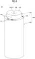
- FIG. 1 is an overall view of a discharge container according to a first embodiment of the present invention.
- the discharge container of the present invention contains, for example, a cosmetic agent (a basic cosmetic agent, a cosmetic agent for base makeup, and a cosmetic agent for point makeup), a kneaded perfume, a seasoning, and the like as contents.
- a cosmetic agent a basic cosmetic agent, a cosmetic agent for base makeup, and a cosmetic agent for point makeup
- a kneaded perfume a seasoning, and the like as contents.
- the discharge container 1 As illustrated in FIG. 1 , the discharge container 1 according to this embodiment is surrounded by a container body (cover, case) 10 having a discharge face 13 on which a discharge hole 15 is formed.
- the container body 10 is formed by combining cylinders of different diameters in a stepped shape.
- the container body 10 is formed of a discharging cylinder 11 and a receiving cylinder 12.
- the discharging cylinder 11 and the receiving cylinder 12 are illustrated to be in a cylindrical shape, but it may be in a shape of rectangular cylinder.
- an operation unit (operation switch) 101, a light emitting unit 102, and a power switch 103 are provided on the upper surface near the outer periphery of the receiving cylinder 12 as an example of the outer surface of the receiving cylinder 12.
- the operation unit 101 adjusts the discharge amount (mixing ratio) of the discharged contents.
- the light emitting unit 102 emits light so as to indicate a selected amount of discharge selected by the operation unit 1011.
- FIG. 1 a display example in which the discharge amount can be selected in three stages for a plurality of types of contents is illustrated.
- FIG. 1 illustrates two sets of an operation unit 1011 and the light emitting unit 102, three or more kinds of contents may be included in the discharge container 1.
- the discharge amount is selected in the three stages, for example, when none of the light emitting unit 102 is illuminated, the "no discharge" of the contents thereof is indicated; when one light is illuminated, the “discharge amount is small”; when two light are illuminated, the “discharge amount is medium”; and when three light is illuminated, the "discharge amount is large”.
- the number of operation units 101 may be increased or decreased depending on the number of types of contents inside the discharge container 1.
- the shape of the operation unit 1011 is illustrated as a triangle in FIG. 1 . However, the shape of the operation unit 1011 may be any other shape provided that the discharge amount of the contents can be manipulated.
- the power switch 103 turns ON/OFF the power supply 91 of the discharge container 1 (see FIG. 7 ).
- the upper surface of the container body 10 is the discharge face 13, and a recess 16 that is recessed inwardly is formed in a bowl-shaped (pan-shaped) around the discharge hole 15 on the discharge face 13.
- a piston 3 is provided in the discharge space 2 inside the discharge hole 15 (see FIG. 2A ).
- the circumference of the piston 3 provided in the discharge space 2 in communication with the discharge hole 15 and the discharge hole 15 are of the same size.
- the piston 3 is in the first position when the power supply is turned OFF or when the power is turned ON after discharge and in the standby position.
- the top face 31 of the piston 3 is substantially identical to the opening face 14 of the discharge hole 15 (see FIG. 2A ).
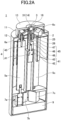
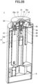
- FIGS. 2A and 2B are examples of cross-sectional views of the discharge container of FIG. 1 .
- a cylinder part 25 having a discharge space 2 is provided inside the container body 10, and a piston 3 is installed in the discharge space 2.
- the discharge space 2 that communicates with the discharge hole 15 (opens) inside the container body 10 and is surrounded by the inner wall 21 is formed.
- the piston 3 fits inside the inner wall 21 of the discharge space 2 and is movable between a first position illustrated in FIG. 2A and a second position illustrated in FIG. 2B that is apart from the discharge hole 15 by the first position thereof.
- the head of the piston 3 in FIGS. 2A and 2B is cylindrical or elliptical cylindrical, in which the side surface 32 is adhesive to the inner side (inner wall 21) of the discharge space 2.
- the container body 10 further includes a plurality of storage portions 5a to 5e for each of a plurality of storage portions of different types.
- FIGS. 2A and 2B are longitudinal cross-sectional views, the two front storage portions 5a and 5c are visible in the drawings.
- the five storage portions 5a, 5b, 5c, 5d, and 5e are provided in the discharge container 1 because the plurality of storage portions are also provided in the front and rear of the FIGS. 2A and 2B .
- Inlet holes 22a to 22e are formed in the inner wall 21 of the discharge space 2, respectively, corresponding to the storage portions 5a to 5e.
- the inlet holes 22a to 22e communicate with (are opened) the discharge space 2 between the top face 31 of the piston 3 and the discharge face 13, and the contents are respectively able to enter the discharge space 2 from the inlet holes 22a to 22e.
- a sealing portion 33 is provided in the portion in contact with the inlet holes 22a to 22e when the piston 3 is in the first position to improve sealing for sealing the inlet holes.
- the seal portion 33 of the piston 3 is made of HDPE (high density polyethylene) or PP (polypropylene) and the seal portion 33 of the piston 3 is made of a soft material such as NBR (nitrole rubber), silicone rubber, thermoplastic elastomer (olefinic, styrene).
- HDPE high density polyethylene
- PP polypropylene
- NBR nitrole rubber
- silicone rubber silicone rubber
- thermoplastic elastomer olefinic, styrene
- each of the storage portions 5a to 5e of the plurality of storage portions and each of the inlet holes 22a to 22e are connected, respectively, with a plurality of supply passages 6a to 6e through which each of the plurality of contents passes.
- discharge container 1 illustrated in FIGS. 2A and 2B is provided with the extrusion parts 7a to 7e at the lower side of the storage portions 5a to 5e.
- the piston 3 is driven to move by a piston driving unit 4 provided at the lower portion of the piston 3.
- the piston 3 can be moved up and down between the first position illustrated in FIG. 2A and the second position illustrated in FIG. 2B .
- the piston 3 moves up and down the inside of the cylinder part (cylinder portion) 25 constituting the discharge space 2.
- a stopper 26 is provided between the piston 3 and the piston drive unit 4 to regulate the position of the piston 3 when the piston 3 is in the lowest second position.
- the stopper 26 is generally cylindrical and is positioned so that the outer peripheral surface fits into a portion of the inner wall 21 of the cylinder part 25, and the upper surface of the stopper 26 functions as the bottom of the discharge space 2.
- the piston drive unit 4 includes a piston motor 41 which is a rotating motor (positioning gear motor) generating rotating force and a rotation conveyer 45 which is a connecting screw (rotation screw) interposed between the piston motor 41 and the piston 3.
- a piston motor 41 which is a rotating motor (positioning gear motor) generating rotating force
- a rotation conveyer 45 which is a connecting screw (rotation screw) interposed between the piston motor 41 and the piston 3.
- a piston rod 35 having the shape of an female threaded piston having a lower opening and a spiral groove on an inner peripheral surface is formed below the discharge hole 15 of the piston 3.
- a piston rod 35 is formed through the hollow portion of the stopper 26.
- the rotation conveyer 45 has a male threaded bearing shape, and a male screw 47, which is an upper protruding screw portion, is formed on the upper side of the rotation conveyer 45 that fits with the piston 3.
- a bearing hole 48 is formed in the threaded head portion 46 below the rotation conveyer 45 to engage the rotation shaft 43 which is driven to rotate by the motor portion 42 in the piston motor 41.
- the rotation conveyer 45 transmits the rotation force of the piston motor 41 as the movement force of the piston 3.
- a plurality of protrusions or grooves extending vertically are provided in an asymmetric manner, and the protrusions or grooves engage the grooves or protrusions extending vertically provided on the inner surface of the stopper 26.
- the piston drive unit 4 is configured by a piston motor (rotary motor) 41 and a rotation conveyer 45 configured by a rotation screw.
- a wound spring may be used in place of the rotation screw, or another drive motor may be used in place of the rotation motor.
- the plurality of extrusion parts 7a to 7e adjusts the supply amount (the inflow amount) of each contents from each storage portion to the discharge space 2, pushes out each content from each storage portion 5a to 5e, and transfers them to each inlet hole 22a to 22e via each supply passage 6a to 6e.
- the plurality of extrusion parts 7a to 7e are constructed, for example, of a gear motor and function as a plurality of extrusion-type transfer units.
- the extrusion parts will be described in detail with respect to FIGS. 5A-6 .
- the storage portions 5a to 5e each having the extrusion part (pusher portions) 7a to 7e at the bottom thereof have, for example, a dispenser structure and the storage portions 5a to 5e are lifted as one push to transfer the contents from the storage portions 5a to 5e to the inlet holes 22a to 22e in a predetermined amount.
- the extrusion parts 7a to 7e are pushed up by one push for a predetermined height and the storage portion 5a to 5e, so that the discharge amount per one push pushed out by the storage portions 5a to 5e is defined, and the number of pushes in one discharge operation can be increased or decreased according to the adjusted discharge amount.
- the extrusion parts 7a to 7e may be configured as an ejection type piston 54 (see FIG. 6 ) which moves inside the storage portions 5a to 5e in a manner similar to the piston drive unit 4 described above, and an ejection driving portion which drives the respective color pistons 54.
- the unwinding amount can be adjusted by adjusting the rotation amount of the extrusion parts 7a to 7e (the rotation shafts 72 of the motor 71) according to the adjusted discharge amount.
- the supply amount by the extrusion parts 7a to 7e is controlled by the controller 9.
- the control of the supply is described in detail with FIG. 7 .
- the circumference of the piston 3 and the discharge hole 15 are of the same size, and when the piston 3 is in the first position, the surface (the opening face 14) of the lowest portion of the recess 16 of the discharge face 13 and the top face (the upper face in the present embodiment) 31 of the piston 3 are substantially the same height.
- the contents contact only the upper surface of the piston without contacting the bottom surface 34 of the piston 3, ride on the top face 31 of the piston 3, and are conveyed to the position of the discharge face 13 of the container body 10 as the piston 3 rises.
- the discharge container of the present invention has no contents left in the discharge space 2 without cleaning the inside of the container, and no dust or the like is deposited. Therefore, when the discharge container is used by changing the mixing ratio during the next use, it is not necessary to perform the discharge operation without considering the mixing ratio status of the previous contents. In addition, because a plurality of holes is effectively sealed, the volatilization of the contents can be prevented except during the discharge operation.
- the diameter of the discharge hole 15 is consecutively with the internal diameter of the cylinder part 25 constituting the discharge space and is configured to be approximately the same size. That is, because the discharge hole 15 is configured with a dimension that can be closely adhered to the peripheral diameter of the piston 3, the contents riding on the top face 31 of the piston 3 are extruded on the top face 31 without being subjected to the pressure from the side while maintaining the same area as when the piston flowed in.
- the user can view the movement of the contents flowing in from the inlet holes 22a to 22e and the movement of the piston 3 in the discharge space 2, so that the user can enjoy the discharge operation of the discharge container 1.
- a piston rod 35 having the shape of a female screw is provided on the lower side of the piston 3, and the rotation conveyer 45 is a male threaded bearing.
- a male and a female screw may be opposite. That is, a male screw may be provided on the underside of the piston 3 and the rotating carrier may be a female threaded bearing.
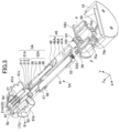
- FIG. 3 is a perspective view illustrating an exploded cross-sectional view of an internal configuration in which a case of a discharge container 1A in which a rotation conveyer 45A is made of a female threaded bearing is removed.
- a rotation conveyer 45A is made of a female threaded bearing is removed.
- FIG. 3 an example in which the piston 3A is disassembled in a first position is illustrated.
- only one storage portion and its periphery are illustrated for the storage portion 5A.
- the components hidden in FIGS. 2A and 2B will now be described with reference to FIG. 3 .
- the assembly of the +Z side illustrates the interior of the upper fixing support 17 (see FIG. 5A ), and the supply passages 6a to 6e are formed below the upper plate 17U of the upper fixing support 17, the cylinder part 25, the plurality of storage portion-side holders 61a to 61e, and the cylinder part 25 and the storage portion-side holders 61a to 61e respectively.
- FIG. 3 is a cross-sectional view. All of the main body side holders 61a to 61e on the storage portion side that are provided in the same number as the type of the contents are not illustrated, but only the number that can be appropriately viewed according to the angle, etc. are illustrated.
- the inner wall 21A of the cylinder part 25 is illustrated as the cylinder part 25.
- the assembly on the-Z side also illustrates the interior of the lower fixing support 18 and is provided with a rotor bearing holder 181 having a bearing rubber 182 mounted thereon above the upper plate 18U of the lower fixing support 18.
- Motor holders 75a to 75e (75a to 75d are illustrated) are provided below the upper plate 18U of the lower fixing support 18.
- An extruder motor 7a (see FIG. 6 ) shall be installed in the internal space ⁇ of the motor holder 75a to 75e.
- a piston motor 41 (see FIGS. 2A and 5B ) is installed in the central space ⁇ surrounded by the motor holders 75a to 75e, and the piston motor 41 is connected to the bearing hole 48 of the rotation conveyer 45A via a bearing held in the rotary bearing holder 181.
- piston 3A has a top face 31A and a cylindrical portion 32A.
- the top face 31A has a convex portion 311 and a front side portion (a flat portion) 312 around the convex portion 311 as a portion in contact with the contents. Further, in the example illustrated in FIG. 3 , the inlet hole 22 is blocked by the distal side portion 313 which is a side of a portion other than the convex portion 311 of the top face 31A. Therefore, the top face 31A is made of a soft material such as NBR, silicone rubber, thermoplastic elastomer, and the like as well as the seal portion 33 of FIG. 2B .
- the cylindrical portion 32A of the piston 3A is made of, for example, HDPE or PP.
- the distal end of the cylindrical portion 36 is provided with an engagement projection 38 for engaging the top face 31A.
- the inner wall 21A of the cylinder part 25 on the +Z side of FIG. 3 has a plurality of stretching grooves 27 extending along the vertical direction of the piston 3A in the direction of travel.
- the outer peripheral surface of the cylindrical portion 36 of the piston 3A is provided with a plurality of elongated projections 37 which engage the elongated grooves 27.
- the rotation conveyer 45A illustrated in FIG. 3 has an H-shaped female threaded bearing shape
- the distal end of the piston 3A has a female threaded configuration
- a rotation groove 49 is formed in the inner wall.
- a helical projection 39 is formed as a transmission portion under the outer circumference of the cylindrical portion 36 of the piston 3A.
- the end face of the female threaded portion in which the rotation groove 49 is formed functions as a stopper face 46As.
- the piston 3A is rotated from the H-shaped rotating carrier 45A by helical engagement, and the elongated projection 37 of the piston 3A moves along the elongated groove 27 within the inner wall 21A of the cylinder part 25 so that the piston 3A moves in the desired direction of progression without rotating and while the position is regulated.
- the main body cylinder 51 of the storage portion 5A is retained by a storage portion holder 57 having a fixed projection 58. Meanwhile, the bearing 56 fits into the fitting protrusion 52G formed inside the operation cylinder portion 52 of the storage portion 5A, and the rotation shaft 72 (see FIG. 6 ) of the extrusion part (extrusion drive part ) 7A is inserted into the bearing 56.
- a fixed projection 58 is formed in a storage portion holder 57 for holding main body cylinder 51.
- a groove 62 extending in up and down directions are formed in the main body side holder 61 (61a to 61e).
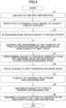
- FIG. 4 is a flow chart illustrating the operation of the discharge container of the present invention.
- the flow procedure is preset by a program stored in the controller 9.
- step S1 of Fig. 4 the user sets the mixing ratio of the contents and enters it into an instruction unit.
- the instruction unit is an operation unit 101.
- a user may input information through an information processing terminal connected by a network.
- step S2 the controller 9 determines a usage amount (discharge amount) of the plurality types of the contents based on the mixing ratio that is predetermined.
- step S3 in the discharge space 2, the piston 3 is moved from the first position to the second position. That is, in the discharge space 2, the piston 3 moves from a position in which the inlet holes 22a to 22e of the inner wall 21 of the cylinder part 25 are blocked to a position in which the inlet holes 22a to 22e are blocked, to a position in which the lower surface portion contacts the stopper 26 (or the stopper face 46As) and the inlet holes 22a to 22e are opened.
- step S4 the contents are transferred, so that a plurality of types of the contents enter into the discharge space 2 from a plurality of inlet holes 22a to 22e.
- step S4 in the case of an feed type extrusion part of the dispenser type, the extrusion part 7a to 7e push the contents from the storage portions 5a to 5e by pushing the storage portions 5a to 5e from the bottom toward the inlet holes 22a to 22e.
- the extruder (extrusion drive unit) 7A pushes the contents in the storage portion 5A toward the inlet holes 22a to 22e by pushing the contents in the storage portion 5A by each color piston 54 which is raised by rotation.
- the contents may be moved from the storage portions 50a to 50e (see FIGS. 9A and 9B ) to the inlet holes 22a to 22e by the pumps 8a to 8e in the supply passages 60a to 60e.
- the contents fed at the time of the previous use may reach the inlet holes 22a to 22e or the vicinity of the inlet holes 22a to 22e. Therefore, other than immediately after the start of use, the inlet holes 22a to 22e of the inner wall of the cylinder part 25 are opened by the movement of the piston 3 in step S3, and the contents are transferred by a transfer unit, so that the contents of the plurality of types immediately flow from the plurality of inlet holes 22a to 22e into the discharge space 2.
- the inlet from the plurality of inlet holes 22a to 22e to the discharge space 2 may be flowed simultaneously between the plurality of the contents, or the inlet from one or the plurality of the contents may be flowed at the respective timings in order.
- step S5 When a plurality of contents of a plurality of types enter the discharge space 2 in a predetermined amount (step S5), in step S6, the piston 3 is moved from a second position to a first position in the discharge space 2.
- step S6 As the piston 3 of step S6 moves, the plurality of contents in the discharge space 2 ride on the top face 31 of the piston 3 and are extruded to the same height as the discharge face 13 of the container body 10 (step S7).
- step S8 the user mixes a plurality of types of contents on the discharge face 13 (step S8) and uses the mixture (step S9).
- a user can enjoy mixing the contents by himself or herself.
- a recess 16 is formed in the discharge face 13 which is the upper surface of the container body 10, at a portion surrounding the discharge hole 15. Therefore, when the user mixes a plurality of extruded contents more inside the edge of the recess 16 with the recess 16 as a tray, the user can efficiently use the mixture.
- FIGS. 5A and 5B are diagrams illustrating the configuration of a plurality of extrusion part -type storage portion in which the receiving cylinder 12 of the discharge container 1 is removed.
- FIG. 5A is a side view of a plurality of extrusion receptacles with the receiving cylinder 12 of the discharge container 1 removed
- FIG. 5B is a view viewed from another angle with the fixing supports 17 and 18 removed from FIG. 5A .
- the discharge container 1 is provided with five storage portions 5a to 5e, the extrusion parts 7a to 7e, and the supply passages 6a to 6e.
- the inside of the receiving cylinder 12 is provided with a fixing support 17 for fixing the position of the tubular supply passages 6a to 6e in the vertical direction and the circumferential direction at the upper side, and a fixing support 18 for fixing the position of a part of the cylindrical storage portions 5a to 5e and the positions of the extrusion parts 7a to 7e at the lower side.
- FIG. 5A the upper side of the cylindrical storage portions 5a to 5e is provided with a dispenser part D of an upper discharge type, which is discharged upward by a push inside the fixing support 17.
- a dispenser part D of an upper discharge type which is discharged upward by a push inside the fixing support 17.
- FIG. 5A only the dispenser part D mounted to the storage portion 5a is illustrated. However, the dispenser part is similarly provided at the upper part of the other storage portions 5b to 5f.
- the extrusion parts 7a to 7e which are the push-up portions, are provided in a straight lines at the lower sides of the cylindrical storage portions 5a to 5e, and the cylindrical storage portions 5a to 5e are pushed up from the lower side to the upper side, so that the pump function of the dispenser D fixed to the inside of the fixing support 17 is activated.
- the contents accommodated in the storage portions 5a to 5e are absorbed by the dispenser D in a predetermined amount per a push by the extrusion parts 7a to 7e and pushed up into the supply passages 6a to 6e formed in the discharging cylinders 11 on the upper side.
- the storage portions 5a to 5e, the extrusion parts 7a to 7e, and the supply passages 6a to 6e are integrally provided in the discharge container 1. Therefore, when the contents are lost, the cartridge including "the storage portion + the extrusion part + the supply passage" is replaced as a unit.
- FIG. 6 illustrates a drawing in which one of an extending type extrusion way storage portion 5A and an extrusion part (extending drive part) 7A having a different configuration from FIG. 5 are drawn out.
- the storage portion 5A includes a main body cylinder 51 as a storage case and an operation cylinder 52 connected to the main body cylinder 51. Inside the main body cylinder 51 and the operation cylinder 52, a movable body 53 is contained so as to penetrate thereto.
- the main body cylinder 51 includes a filling area in which the contents C are filled.
- the operation cylinder 52 is disposed at a rear end of the main body cylinder 51 in a relative rotation manner.
- the main body cylinder 51 and the movable body 53 contained in the operation cylinder 52 move forward (in the left direction in FIG. 6 ), and when each color piston 54 provided at the distal end of the movable body 53 moves forward, the contents C are pushed out toward the distal end.
- the contents C are pushed into the supply passage 6 (6a to 6e) (see FIGS. 2A and 3 ) mounted to the diameter small portion 55 through the diameter small portion 55 at the distal end of the main body cylinder 51.
- the axial movable body 53 does not penetrate the piston 54, but exists only on the lower side of the piston 54 (the rear end side, to the right side of FIG. 6 ). Accordingly, the upper contents C of the piston 54 can be extruded without adhering to the movable body 53 because the movable body 53 is not present on the upper side of the piston 54 (the distal end (the left side of FIG. 6 ).
- the periphery of the small portion 55 on the upper side of the main body cylinder 51 can have a simple configuration. Therefore, when the diameter small portion 55 is inserted into the supply passages 6a to 6e through which the opening formed on the lower surface of the discharging cylinder portion 11 of the size suitable for the diameter small portion 55 is inserted, the contents C are pushed out by the piston 54 transmitting power from the lower side, without requiring a power source or a power transmission member on the side of the discharging cylinder portion 11 at the top face portion of the container body 10.
- the main body cylinder 51 is fixed by a storage portion holder 57 and a main body side holder 61 with respect to the receiving cylinder 12 regulated in rotation in a circumferential direction.
- a bearing 56 is provided in the tail plug portion which is at the lower end of the operation cylinder 52 and has a small inside diameter.
- a rotation shaft (output shaft) 72 of a motor 71 constituting an extrusion part 7A is connected to a bearing 56.
- the motor 71 which is an extrusion part of the acceleration type, is provided in a straight line under the storage portion 5A, when the motor 71 is set as illustrated in FIG. 3 and is mounted upright as illustrated in FIG. 1 , power is directly transmitted from the bottom to the operation cylinder 52 in the storage portion 5A. That is, when power is supplied from the wiring 73 and the motor 71 of the extrusion part 7A rotates the rotation shaft 72, the rotation force is transmitted to the operation cylinder 52 through the bearing 56, and the operation cylinder 52 rotates relative to the main body cylinder 51, so that each color piston 54 rises and the contents C is pushed out from the upper diameter small portion 55 to the supply passage 6.
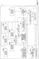
- FIG. 7 is an example of a control block diagram of the discharge container 1.
- a five-color cosmetic agent is illustrated as a cyan, magenta, yellow, black, or white cosmetic agent used in, for example, a point cosmetic agent.
- a piston motor 41 for driving the piston 3 is provided as a part of the piston drive unit 4.
- a cyan motor 7a, a magenta motor 7b, a yellow motor 7c, a black motor 7d, and a white motor 7e, which are extruding portions (pushing portions) for extruding the contents from each of the storage portions 5a to 5e, and a dispenser portion D for extruding the contents by pushing by these motors are provided as an extrusion part type transfer unit.
- a motor 71 constituting the extrusion part (extrusion drive part) 7A drives and rotates the piston, and each color piston 54 is provided as an extrusion type transfer unit to push the contents up.
- the control board 90 constituting the controller 9 includes a power supply 91, a main control unit 92, a piston control unit 93, and a supply control unit 94.
- the power supply 91 is a source of power for the entire discharge container 1 and is controlled by the power switch 103.
- the piston control unit 93 drives a piston motor 41.
- the supply control unit 94 sets the respective supply amounts of the plurality of contents that flow into the discharge space 2 through the plurality of supply paths and the plurality of inlet holes from the plurality of storage portions.
- the supply control unit 94 includes a mixing/discharge amount setting unit 95 and a parameter converting unit 96.
- the mixing/discharge amount setting unit 95 sets the mixing ratio of a plurality of contents based on the instruction of the information on the mixing and sets the supply amount of each of the plurality of contents.
- the parameter converting unit 96 converts the respective supply amount of the set plurality of contents to a parameter.
- the supply amount (the extrusion transfer amount) of the plurality of contents is adjusted by controlling the number of operation pushes and the operation time of each color motor (the extrusion part) 7a to 7e as the transfer unit as parameters. Then, based on the set parameters, power is supplied to each color motors 7a to 7e that are the extrusion part transfer unit.
- the main control unit 92 adjusts the timing for operating the supply control unit 94 and the piston control unit 93.
- the piston control unit 93 promptly supplies power to the piston motor 41 after receiving an instruction from the operation unit 101 to move the piston 3 from the first position to the second position.
- the supply control unit 94 drives the extrusion part (motors 7a to 7e) at a timing after the piston 3 moves to the second position to feed the set plurality of contents into the discharge space 2.
- the piston control unit 93 supplies power to the piston motor 41 and moves the piston 3 from the second position to the first position at a timing after the set plurality of contents are supplied to the discharge space 2.
- the operation unit 1011 is an instruction receiving unit according to the present embodiment and receives an instruction of information regarding the mixture of a plurality of contents.
- the light emitting unit 102 emits light to indicate the current state operated by the power switch 103 and the operation unit 101.
- the power switch 103 turns the power supply 91 on and off.
- FIG. 8 is an overall view of the discharge container 1B according to a second embodiment of the present invention, this second embodiment not being covered by the subject-matter of the claims.
- the diameter of the discharge hole 19 is smaller than the circumferential diameter of the piston 3B (see FIG. 9A ).
- a convex portion 311 is formed in the center of the top face 31B that is an end surface of the discharge hole side of the piston 3B (see FIG. 9A ).
- the top face of the convex portion 311 of the piston 3B is substantially the same as the opening face 14B of the discharge hole 19 (see FIG. 9A ) or higher than the opening face 14B.
- FIGS. 9A and 9B are an internal schematic views of the discharge container 1B of FIG. 8 , wherein FIG. 9A illustrates a state where the piston 3B is in a second position and FIG. 9B illustrates a state where the piston 3B is moving from a second position to a first position.
- the discharge space 2B, the piston 3B, the plurality of storage portions 50a and 50b, the supply passages 60a and 60b, and the pumps 8a and 8b are provided inside the discharge container 1B according to the present embodiment.
- the discharge space 2B communicates with the discharge hole 19 formed in the discharge face 13B.
- the top face of the convex portion 311 of the piston 3B is substantially at the same position as the opening face 14B of the discharge hole 19, and the distal face portion 312 other than the convex portion of the piston 3B is at a height that abuts the inner side surface (lower surface) 161 of the discharge face 13B or the recess 16.
- the distal face portion 312 of the piston 3B may have a shape corresponding to the inner surface shape of the discharge face 13B, be a plane surface as illustrated in FIG. 9B , be inclined so as to be high toward the convex portion 311 of the central portion as illustrated in FIG. 3 , or be inclined so as to be low toward the convex portion 311.
- the diameter of the discharge hole 19 is small, a plurality of types of the contents discharged are conveyed onto the discharge face 13B after receiving pressure. Therefore, in the discharge container 1B according to the present embodiment, the contents are extruded while being mixed slightly. Accordingly, the user can enjoy the gradual injection of a slightly mixed discharge, and can reduce the time required for the mixing of the contents extruded from the discharge hole on the discharge face 13B.
- the pumps 8a and 8b are used as a method of supplying the contents Ca and Cb from the storage portions 50a and 50b to the discharge space 2B.
- the pumps 8a and 8b are provided in each of the supply paths of the plurality of supply paths.
- the storage portions 50a and 50b there are two examples of the storage portions 50a and 50b, the corresponding pumps 8a and 8b, and the supply passages 60a and 60b.
- the number of storage containers may be any as long as plural.
- the pumps 8a and 8b are suction type transfer unit which adjusts the supply amount of each contents Ca and Cb flowing into the discharge space 2B from each of the storage portions 50a and 50b, draw each contents Ca and Cb from each of the storage portions 50a and 50b in each of the supply passages 60a and 60b, and transfer them to the inlet holes 22a and 22b.
- the pumps 8a and 8b are adjusted by the above-described supply control unit 94 to adjust the supply amounts of the respective contents Ca and Cb from the respective receiving units 50a and 50b to adjust the ratio of the plurality of contents when they are discharged from the discharge hole 19.
- the supply control unit 94 converts the respective supply amount of the set plurality of contents that are set into a parameter.
- the suction amounts of the pumps 8a and 8b which are the suction type transfer unit, are controlled to adjust the supply amounts (the suction transfer amount) of the plurality of the contents Ca and Cb.
- the piston 3B is moved to the first position to push a plurality of contents flowing into the discharge space 2B out of the discharge hole 19 to the discharge container 1B.
- the discharge hole 19 having a diameter smaller than the diameter of the discharge space 2B illustrated in FIG. 8 may be used as the discharge hole, and the extrusion parts 7a to 7e and 7A (a transfer drive with a dispenser type extrusion part or an extending type extrusion part) may be used as the transfer method of the contents as illustrated in FIG. 5A or FIG. 6 .
- the discharge hole 15 having a diameter substantially the same as that of the discharge space 2 may be used as the discharge hole, and the pumps 8a and 8b (suction way transfer driving) may be used as the transfer type of the contents as illustrated in the center portions of FIG. 9A and FIG. 9B .
- FIG. 10 is a diagram illustrating another use state of the discharge container of the present invention.
- the discharge containers 1, 1A, and 1B are disposed to be discharged upwardly.
- the direction of discharge is not limited to the upward direction but may be the downward direction as illustrated in FIG. 10 .
- the discharge container 1C when the discharge container 1C is arranged so as to be discharged downward, the contents may be discharged onto the hand of the user and mixed together on the palm of the hand, as in the case of a hand wash which is fixedly installed.
- the operation unit 101 and the light emitting unit 102 are disposed at a suitable position for easy viewing, such as a side surface, so that the operation unit 101 is visible to the user.
- the discharge face 13C on which the discharge hole 19C is formed is the lower surface of the container body 10C, as an example. Therefore, the piston inside the container can be moved up and down between the first position below and the second position above. In this configuration, when the power supply is turned OFF, or when the piston is in the discharge and standby positions, the piston is in the first position below, and the surface of the discharge face (lower surface) 13C and the lower surface of the piston are at approximately the same height.
- the contents when discharging the contents in the downward direction in the discharge container 1C, it is preferable that the contents have a high viscosity in consideration of gravity. In view of gravity, it is preferable that the configuration be smaller than the diameter of the discharge space communicated by the discharge hole 19C as illustrated in FIG. 8 .
- the circumference of the discharge hole 19C is not a structure in which the discharge hole 19C is concave as in the first and second embodiments, but a convex portion 16C protruding in a mountain-like manner from the discharging surface 13C.
- FIG. 10 a configuration to be discharged downwardly is illustrated, but the direction of discharge is not limited to the upward and downward directions but may be a lateral direction.
- the piston may be raised and lowered manually.
- the transfer unit when the transfer unit transfers the contents corresponding to the predetermined number of pushes, the rotation amount of the operation cylinder, and the amount of suction, which are used for one discharge, and a predetermined amount of the plurality of the contents is flowed into the discharge space, the transfer unit notifies the discharge space to that effect by sound or light. Then, a user pushes a button or pulls up or down a projection connected with the piston to move the piston and discharge the plurality of contents.
- FIG. 11 is a schematic diagram of a customized discharge system including a discharge container according to a fourth embodiment of the present invention.
- the user instructed the discharge amount (mixing ratio) by the operation unit 101 provided in the container body 10.
- the discharge container 1D it is possible to receive an instruction of information concerning the mixture of a plurality of contents from an information processing terminal which is an external device capable of communicating with the discharge container 1D via a network.
- a communication unit 97 (see FIG. 12 ) is provided at a part of the control board 90D of the discharge container 1D, and the communication unit 97 is capable of communicating with a computer 200 or a smartphone 300 that is an information processing terminal.
- the information processing terminals 200 and 300 have an instruction reception function for receiving an instruction of information on the mixture of a plurality of contents of the discharge container 1D by downloading an application in advance or the like.
- the user inputs information concerning the discharge amount (mixing) of the discharge container to the information processing terminal 200,300.
- the discharge container 1D and the information processing terminals 200 and 300 are called the customized discharge system 1000 in combination.
- the discharge container 1D includes, for example, a container body, a piston movable in the discharge space, a plurality of storage portions, a plurality of supply passages, a pushing type or extending type, extrusion way or suction way, transfer unit, a controller, and so on in a manner similar to any of the first to third embodiments described above, in the present embodiment.
- a plurality of inlet holes corresponding to the plurality of storage portions are formed in the inner wall of the discharge space, for example.
- the discharge container 1D sets the supply amount of each of the plurality of contents that flows from the plurality of the information processing terminals 200 and 300 into the discharge space through the plurality of supply paths and the plurality of inlet holes based on the instruction of the mixing information input to the information processing terminals 200 and 300.
- FIG. 11 an example in which an operation unit is not provided in the discharge container 1D that can be communicated is illustrated.
- an operation unit may be further provided in the discharge container that can be communicated in order to be operated even at hand in addition to instructions from the information processing terminals 200 and 300.
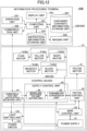
- FIG. 12 is a functional control block diagram of the customized discharge system 1000 in FIG. 11 .
- the discharge container 1D included in the customized discharge system 1000 is provided with a communication unit 97 as an instruction receiving unit that receives information transmitted by external devices (information processing terminals 200 and 300) capable of communicating via a network.
- the information processing terminal 200 includes a computing unit 201, a container internal content information storage unit 202, a display unit 203, an instruction information storage unit 204, and a communication unit 205.
- the ratio of the contents and the discharge amount may be directly set in the discharge container 1D in a manner similar to that in the operation unit 101.
- an operation unit 207 on the information processing terminal 200 and 300 may select the information based on the information after completion from the information separated from the information according to the application (information of the contents inside the container) stored in the information processing terminals 200 and 300.
- the information processing terminal 200 and 300 store in advance the ratio (mixing) of the discharge amount of each content and the completed color tone and skin feel after mixing in the inside of the container information storage unit 202. Then, the color taste and skin feel information after mixing in the predetermined ratio is displayed on the display unit 203, and the user selects the information based on the color taste and skin feel information after mixing. This selection reduces a load on the user to consider the mixing ratio of the contents.
- the information processing terminal 200 displays a plurality of model colors, for example, the skin colors of ochre, beige, and ivory after mixing, in a step-wise manner by the display unit 203. Then, the user selects the color on the screen, and the computing unit 201 calculates the mix of discharge in accordance with the selected image display color.
- the communication unit 205 transmits the calculated information to the discharge container 1D, and the discharge container 1D causes the contents of a plurality of different colors to be discharged simultaneously at a predetermined mixing ratio based on the information, and when the user mixes the contents, the color becomes a predetermined complete color.
- a cosmetic agent for partial makeup is prepared for the content (cosmetic agent) having different colors, for example, color of lucent (transparent), white, pink, red, purple, blue, green, brown, or the like may be selected in stages for each color.
- the information processing terminal 200 displays the model color of the color tone in the display unit 203 and selects the color on the screen, so that the computing unit 201 calculates the mix of discharge in accordance with the selected image display color.
- a cosmetic for partial make-up is prepared by mixing the above-described cosmetic agents, by changing the discharged color, multiple colors can be enjoyed in one discharge container, and by changing the color setting, multiple applications (for example, eye gross and lip gloss, highlight, shadow, cheek) can be used in one unit.
- the contents having different colors are described as the contents.
- the contents having different tactile feelings may be used.
- the mixing ratio of the contents that are suitable for the selection is calculated by selecting information such as "light”, “moisture”, “normal”, “sensitive”, “whitening”, “anti-acne”, and “for packing” on the information processing terminal 200 in accordance with the skin condition, the ambient air temperature and humidity, and the mood of the user.
- Contents with different tactile sensations are components that affect viscosity.
- the contents with different tactile sensations such as basic ingredients, thickened ingredients (moisturizing ingredients), astringent ingredients, whitening ingredients (vitamin C, etc.), acne control ingredients, etc., are previously contained in contents specializing in different functions.
- the discharge container 1D discharges the contents of the plurality of different viscosities (the tactile feeling on the skin) at the predetermined mixing ratio based on the information.
- the discharged contents are mixed to form a basic cosmetic agent that achieves a predetermined effect.
- the cosmetic agent for the base make when the cosmetic agent for the base make is discharged using the contents having different reflectivity of light, the cosmetic agent may be optionally selectable so that the cosmetic agent having different reflectivity of light to the skin can be discharged by adjusting the mixing ratio of the contents even in the same color by selecting "Natural”, “Gloss (shining)", or “Matte” according to the condition of the skin, the ambient air temperature and humidity, and the mood of the user.
- the contents are stored and transferred separately until the discharge space is reached. Therefore, it is possible to use the contents without deterioration or separation by mixing a plurality of contents which are separated or deteriorated immediately before use.
- Examples of the foregoing include a vitamin C containing cosmetic agent and a hairdressing agent.
- the optimum color combination may be automatically set in the computing unit 201 according to the camera's photographing result.
- an image capturing unit (camera) 206 may be incorporated in the smartphone 300 illustrated in FIG. 11 , or a camera may be mounted to the computer 200, and the skin may be captured by the image capturing unit 206, so that the completed color can be set in accordance with the color of the skin in the photographed image.
- the computing unit 201 of the smartphone 300 automatically selects the color according to the skin color and calculates the mixing ratio, and discharges the color according to the predetermined ratio from the discharge container 1D.
- the color of the make-up color suitable for the skin color may be automatically selected and displayed on the display unit 203 as a recommendation, so that the color can be selected.
- the discharge container of the present invention has been described with the assumption that the user will appropriately select the discharge container for use in the home, but the discharge container is also suitable for use in a counter at a dealer.
- the mixing ratio at the counter it is possible to set the contents of the mixing ratio according to the color and preference of each visitor.
- a cosmetic product that causes a visual change is used as the contents.
- a product having a liquid or viscous fragrance may be used as the contents.
- perfumes or kneaded perfumes By incorporating perfumes or kneaded perfumes into the contents, the user can customize the fragrance.
- contents have been described as a cosmetic as an example, a liquid or viscous seasoning may be contained as the contents.
- a liquid or viscous seasoning may be contained as the contents.
Landscapes
- Engineering & Computer Science (AREA)
- Mechanical Engineering (AREA)
- Chemical & Material Sciences (AREA)
- Chemical Kinetics & Catalysis (AREA)
- Dispersion Chemistry (AREA)
- Containers And Packaging Bodies Having A Special Means To Remove Contents (AREA)
Claims (12)
- Abgabebehälter (1), umfassend:einen Behälterkörper (10) mit einer Auslassfläche (13), in der eine Auslassöffnung (15) ausgebildet ist,einen Zylinderteil (25) mit einem Auslassraum (2), der mit der Auslassöffnung (15) im Inneren des Behälterkörpers (10) in Verbindung steht;einen Kolben (3), der zwischen einer ersten Position und einer zweiten Position beweglich ist, wobei die zweite Position weiter als die erste Position von der Auslassfläche (13) in dem Auslassraum (2) entfernt ist, undeine Vielzahl von Speicherabschnitten (5) zum Speichern von Inhalten,wobei eine Mehrzahl von Einlasslöchern (22), die jeweils der Mehrzahl von Speicherabschnitten (5a bis 5e) entsprechen, in einer Innenwand des Auslassraums (2) ausgebildet sind,wobei, wenn sich der Kolben (3) in der zweiten Position befindet, die Vielzahl von Einlasslöchern (22) mit dem Auslassraum (2) zwischen einer oberen Fläche (31) des Kolbens (3) und der Auslassfläche (13) in Verbindung steht und der Inhalt bereit ist, aus der Vielzahl von Einlasslöchern (22) in den Auslassraum (2) zu fließen, undwobei, wenn sich der Kolben (3) in der ersten Position befindet, die Vielzahl von Einlasslöchern (22) durch den Kolben (3) verschlossen sind, undwobei der Durchmesser der Auslassöffnung (15) im Wesentlichen derselbe ist wie ein Innendurchmesser des Zylinderteils (25), unddie erste Position sich an einer im Wesentlichen gleichen Position wie eine Öffnungsfläche (14) der Auslassöffnung (15) befindet.
- Abgabebehälter (1) nach Anspruch 1, ferner umfassend:eine Vielzahl von Zufuhrkanälen (6), durch die die Vielzahl von Speicherabschnitten (5) und die Vielzahl von Einlasslöchern (22) jeweils verbunden sind und durch die der Inhalt aus der Vielzahl von Speicherabschnitten fließt,wobei nach dem Bewegen des Kolbens (3) von der ersten Position in die zweite Position, um zu bewirken, dass die mehreren Zufuhrdurchgänge (6) und der Auslassraum (2) durch die mehreren Einlasslöcher (22) miteinander in Verbindung stehen und bewirken, dass der Inhalt in den Auslassraum (2) fließt, der Kolben (3) von der zweiten Position in die erste Position bewegt wird, so dass der innerhalb des Auslassraums (2) geflossene Inhalt aus der Auslassöffnung (15) aus dem Abgabebehälter (1) gedrückt wird.
- Abgabebehälter (1) nach Anspruch 2,
wobei in einem Fall, in dem eine Vielzahl von Inhalten unterschiedlicher Art jeweils in der Vielzahl von Speicherabschnitten (6) untergebracht sind, der Abgabebehälter (1) ferner umfasst:eine Befehlsempfangseinheit (97, 101), die einen Befehl über Informationen bezüglich der Mischung der mehreren Inhalte empfängt; undeine Zuführungssteuereinheit (94), die Zuführungsmengen der mehreren Inhalte, die von den mehreren Speicherabschnitten (5) durch die mehreren Zuführungsdurchgänge (6) und die mehreren Einlasslöcher (22) in den Auslassraum (2) strömen sollen, auf der Grundlage der Anweisung über die Informationen bezüglich der Mischung einstellt. - Abgabebehälter (1) nach Anspruch 3, ferner umfassend:eine Mehrzahl von Übergabeeinheiten zum Übergeben der Mehrzahl von Inhalten jeweils in den für jeden der Mehrzahl von eingestellten Inhalten eingestellten Zuführmengen aus der Mehrzahl von Speicherabschnitten (5) an die Mehrzahl von Zuflusslöchern,wobei die Zufuhrsteuereinheit (94) ein Mischungsverhältnis der mehreren Inhalte auf der Grundlage der Anweisung über die Informationen bezüglich der Mischung einstellt, die Zufuhrmengen der mehreren Inhalte einstellt, die eingestellten Zufuhrmengen jeweils in Parameter umwandelt und die mehreren Transfereinheiten jeweils auf der Grundlage der Parameter ansteuert.
- Abgabebehälter (1) nach Anspruch 1, ferner umfassend:
einen Dichtungsabschnitt (33), der an der äußeren Umfangsfläche des Kolbens (3) an einem Abschnitt vorgesehen ist, an dem der Kolben (3) die Einlasslöcher (22) berührt. - Abgabebehälter (1) nach Anspruch 1,
wobei in der Auslassfläche (13) ein Umfangsabschnitt der Auslauföffnung (15) schalenförmig nach innen vertieft ist. - Abgabebehälter (1) nach Anspruch 1,
wobei es sich bei dem Inhalt um Kosmetika handelt. - Abgabebehälter (1) nach Anspruch 3,
wobei die Befehlsempfangseinheit (97, 101) eine Bedieneinheit ist, die an einer Außenfläche des Behälterkörpers (10) angebracht ist. - Abgabebehälter (19) nach Anspruch 3,
wobei die Befehlsempfangseinheit (97, 101) eine Kommunikationseinheit ist, die Informationen empfängt, die von einer externen Vorrichtung übertragen werden, die in der Lage ist, über ein Netzwerk zu kommunizieren. - Kundenspezifisches Entladesystem (1000), umfassend:einen Abgabebehälter nach Anspruch 9; undein Informationsverarbeitungsterminal (200, 300), das in der Lage ist, mit dem Abgabebehälter (1) über das Netzwerk zu kommunizieren, wobei das Informationsverarbeitungsterminal (200, 300) eine Befehlsempfangsfunktion zum Empfangen von Befehlen über Informationen in Bezug auf die Mischung der Vielzahl von Inhalten umfasst.
- Abgabesteuerungsverfahren zum Steuern eines Abgabebehälters (1), der einen Zylinderteil (25) mit einem Auslassraum (2), der mit einer Auslassöffnung (15) in Verbindung steht, einen Kolben (3), der zwischen einer ersten Position und einer zweiten Position, die weiter als die erste Position von einer Auslassfläche (13) in dem Auslassraum (2) entfernt ist, beweglich ist, und eine Vielzahl von Speicherabschnitten (5), die Inhalte speichern, umfasst, wobei der Durchmesser der Auslassöffnung (15) im Wesentlichen derselbe wie ein Innendurchmesser des Zylinderteils (25) ist, und die erste Position sich an einer im Wesentlichen gleichen Position wie eine Öffnungsfläche (14) der Auslassöffnung (15) befindet,
das Verfahren zur Auslasssteuerung umfasst:einen Schritt des Bewegens des Kolbens (3) von der ersten Position in die zweite Position, um im Wesentlichen einen Verbindungszustand herzustellen, in dem eine Vielzahl von Zufuhrkanälen (6) zum Verbinden einer Vielzahl von Einlasslöchern (22), die in einer Innenwand des Auslassraums (2) vorgesehen sind, mit der Vielzahl von Speicherabschnitten (5) durch die Vielzahl von Einlasslöchern (22) mit dem Auslassraum (2) in Verbindung steht;einen Schritt des Bewirkens, dass eine Vielzahl des Inhalts von der Vielzahl der Einlasslöcher (22) in den Auslassraum (2) fließt, undeinen Schritt des Bewegens des Kolbens (3) von der zweiten Position in die erste Position, um den Inhalt, der in den Auslassraum (2) fließt, aus dem Abgabebehälter (1) aus der Auslassöffnung (15) herauszupressen. - Abgabesteuerungsverfahren nach Anspruch 11, wobei das Abgabesteuerungsverfahren in einem Fall, in dem die Mehrzahl von Inhalten unterschiedlicher Art jeweils in der Mehrzahl von Speicherabschnitten (5) untergebracht sind, ferner umfasst:einen Schritt des Empfangens einer Anweisung über Informationen, die sich auf die Mischung der Vielzahl von Inhalten beziehen; undeinen Schritt des Einstellens von Zufuhrmengen der Vielzahl von Inhalten, die in den Auslassraum (2) von der Vielzahl von Einlasslöchern (22) zu dem Auslassraum (2) strömen sollen.
Applications Claiming Priority (2)
| Application Number | Priority Date | Filing Date | Title |
|---|---|---|---|
| JP2017154523 | 2017-08-09 | ||
| PCT/JP2018/028893 WO2019031358A1 (ja) | 2017-08-09 | 2018-08-01 | 吐出容器、該吐出容器を有するカスタマイズ吐出システム、該吐出容器における吐出制御方法 |
Publications (3)
| Publication Number | Publication Date |
|---|---|
| EP3666687A1 EP3666687A1 (de) | 2020-06-17 |
| EP3666687A4 EP3666687A4 (de) | 2021-05-12 |
| EP3666687B1 true EP3666687B1 (de) | 2024-01-17 |
Family
ID=65271510
Family Applications (1)
| Application Number | Title | Priority Date | Filing Date |
|---|---|---|---|
| EP18845014.2A Active EP3666687B1 (de) | 2017-08-09 | 2018-08-01 | Ausgabebehälter, kundenspezifisches ausgabesystem mit ausgabebehälter, und verfahren zur steuerung der ausgabe in einem ausgabebehälter |
Country Status (7)
| Country | Link |
|---|---|
| US (1) | US11203483B2 (de) |
| EP (1) | EP3666687B1 (de) |
| JP (1) | JP7200112B2 (de) |
| KR (1) | KR20200039668A (de) |
| CN (1) | CN110997519B (de) |
| TW (1) | TW201910231A (de) |
| WO (1) | WO2019031358A1 (de) |
Families Citing this family (9)
| Publication number | Priority date | Publication date | Assignee | Title |
|---|---|---|---|---|
| JP7345486B2 (ja) * | 2018-09-10 | 2023-09-15 | 株式会社 資生堂 | 吐出装置及びカスタマイズ吐出システム |
| CN113710371B (zh) * | 2019-04-26 | 2023-11-03 | 株式会社资生堂 | 液状体排出装置及容器 |
| KR102222745B1 (ko) * | 2020-07-10 | 2021-03-04 | 주식회사 통인에이치앤씨 | IoT 기반의 액상 분사 장치 |
| CN112006417A (zh) * | 2020-09-05 | 2020-12-01 | 洽兴包装工业(中国)有限公司 | 按压式化妆笔 |
| JP7822957B2 (ja) * | 2020-11-30 | 2026-03-03 | 株式会社 資生堂 | 化粧料推奨装置、化粧料推奨システム、及び化粧料推奨システムにおける化粧料推奨方法 |
| WO2022124269A1 (ja) * | 2020-12-07 | 2022-06-16 | 株式会社資生堂 | 吐出システム |
| KR20230029260A (ko) * | 2021-08-24 | 2023-03-03 | (주)아모레퍼시픽 | 효소 손상을 방지하는 화장료 조성물 및 이를 저장하는 화장품 용기 |
| JP7835501B2 (ja) * | 2022-12-27 | 2026-03-25 | 株式会社 資生堂 | 化粧料吐出装置 |
| EP4467233A1 (de) * | 2023-05-25 | 2024-11-27 | Sensile Medical AG | Flüssigkeitsspender |
Citations (1)
| Publication number | Priority date | Publication date | Assignee | Title |
|---|---|---|---|---|
| US7445372B1 (en) * | 2004-10-01 | 2008-11-04 | Access Business Group International Llc | Custom cosmetic mixer |
Family Cites Families (27)
| Publication number | Priority date | Publication date | Assignee | Title |
|---|---|---|---|---|
| FR2299578A1 (fr) * | 1975-01-28 | 1976-08-27 | Secmer Sa | Tete pour le melange et le deversement sous pression d'au moins deux produits |
| DE3013237A1 (de) * | 1980-04-03 | 1981-10-08 | Bayer Ag, 5090 Leverkusen | Verfahren und vorrichtung zum herstellen eines aus mindestens zwei fliessfaehigen reaktionskomponenten und fuellstoffen bestehenden, massiv- oder schaumstoff bildenen gemisches |
| US4473531A (en) * | 1981-04-28 | 1984-09-25 | Regents Of The University Of Minnesota | Rim mixhead with high pressure recycle |
| DE3633343A1 (de) * | 1986-09-10 | 1988-03-17 | Bayer Ag | Verfahren und vorrichtung zum herstellen eines kunststoff, insbesondere schaumstoff bildenden, fliessfaehigen reaktionsgemisches aus mindestens zwei fliessfaehigen reaktionskomponenten im durchlauf |
| US5445781A (en) * | 1991-08-28 | 1995-08-29 | Centro Sviluppo Settori Impiego S.R.L. | Process for the injection molding of non-precatalyzed polymerizable resins at high-pressure and flow |
| US5270013A (en) * | 1992-05-06 | 1993-12-14 | Decker Herman W | Reactive fluid mixing head |
| IT1271538B (it) * | 1993-10-15 | 1997-05-30 | Sviluppo Settori Impiego Srl | Dispositivo per lo stampaggio di articoli di materiale composito e procedimento che utilizza tale dispositivo |
| US6047861A (en) * | 1998-04-15 | 2000-04-11 | Vir Engineering, Inc. | Two component fluid dispenser |
| JP2002515309A (ja) * | 1998-05-21 | 2002-05-28 | バクスター・インターナショナル・インコーポレイテッド | シーラントアプリケータおよび衝撃洗浄を使用する方法 |
| FR2791648B1 (fr) * | 1999-04-02 | 2001-05-25 | Oreal | Distributeur portatif pour le conditionnement et la distribution de produits cosmetiques colores |
| JP2004345738A (ja) * | 2003-04-28 | 2004-12-09 | Shiseido Co Ltd | 定量吐出容器 |
| JP4341516B2 (ja) * | 2003-10-03 | 2009-10-07 | 花王株式会社 | 吐出装置 |
| JP4798613B2 (ja) * | 2006-04-27 | 2011-10-19 | 株式会社吉野工業所 | 二液用吐出器 |
| JP5113409B2 (ja) | 2007-03-28 | 2013-01-09 | ホーユー株式会社 | 塗布具及び塗布具付吐出容器 |
| US8224481B2 (en) | 2009-01-19 | 2012-07-17 | Access Business Group International Llc | Method and apparatus for dispensing fluid compositions |
| EP2508217B1 (de) | 2011-04-05 | 2019-09-04 | Kpr U.S., Llc | Anästhesiespritze |
| US9239428B2 (en) * | 2011-09-28 | 2016-01-19 | Ksaria Corporation | Epoxy dispensing system and dispensing tip used therewith |
| KR20140079410A (ko) * | 2011-10-17 | 2014-06-26 | 술저 믹스팩 아게 | 다성분 카트리지 |
| KR101488340B1 (ko) * | 2013-04-10 | 2015-02-02 | (주)연우 | 이종 내용물 혼합용기 |
| GB201308810D0 (en) * | 2013-05-16 | 2013-07-03 | Mcgill Tech Ltd | Container with outlet |
| PL3117909T3 (pl) * | 2014-03-10 | 2026-02-16 | Musashi Engineering, Inc. | Urządzenie aplikujące i sposób aplikacji |
| EP4238637B1 (de) * | 2014-12-02 | 2025-10-29 | L'oreal | System zur ausgabe eines makeup-produkts |
| US10076175B2 (en) * | 2015-03-19 | 2018-09-18 | Jonathan Eng Jin Wee | Device for storing, mixing, and applying cosmetic, skincare, food, or pharmaceutical products |
| US20170144187A1 (en) * | 2015-11-25 | 2017-05-25 | Nordson Corporation | Integrated multicomponent dispensing system and associated methods |
| JP6485387B2 (ja) | 2016-02-29 | 2019-03-20 | トヨタ自動車株式会社 | ハイブリッド車両の制御装置 |
| CN205738644U (zh) * | 2016-05-11 | 2016-11-30 | 上海嘉亨日用化学品有限公司 | 一种化妆品瓶的出料装置 |
| DE102016012651A1 (de) * | 2016-10-24 | 2018-04-26 | Beiersdorf Ag | Mehrkomponentenapplikator |
-
2018
- 2018-08-01 EP EP18845014.2A patent/EP3666687B1/de active Active
- 2018-08-01 US US16/633,705 patent/US11203483B2/en active Active
- 2018-08-01 CN CN201880051115.XA patent/CN110997519B/zh active Active
- 2018-08-01 JP JP2019535144A patent/JP7200112B2/ja active Active
- 2018-08-01 WO PCT/JP2018/028893 patent/WO2019031358A1/ja not_active Ceased
- 2018-08-01 KR KR1020207003152A patent/KR20200039668A/ko not_active Withdrawn
- 2018-08-06 TW TW107127326A patent/TW201910231A/zh unknown
Patent Citations (1)
| Publication number | Priority date | Publication date | Assignee | Title |
|---|---|---|---|---|
| US7445372B1 (en) * | 2004-10-01 | 2008-11-04 | Access Business Group International Llc | Custom cosmetic mixer |
Also Published As
| Publication number | Publication date |
|---|---|
| US20200207538A1 (en) | 2020-07-02 |
| WO2019031358A1 (ja) | 2019-02-14 |
| EP3666687A4 (de) | 2021-05-12 |
| US11203483B2 (en) | 2021-12-21 |
| JP7200112B2 (ja) | 2023-01-06 |
| JPWO2019031358A1 (ja) | 2020-08-13 |
| CN110997519B (zh) | 2022-08-02 |
| TW201910231A (zh) | 2019-03-16 |
| CN110997519A (zh) | 2020-04-10 |
| KR20200039668A (ko) | 2020-04-16 |
| EP3666687A1 (de) | 2020-06-17 |
Similar Documents
| Publication | Publication Date | Title |
|---|---|---|
| US11203483B2 (en) | Discharge container, customized discharge system having discharge container, and discharge control method in discharge container | |
| CN106998876B (zh) | 具有至少两个出口界面的分配系统 | |
| JP6639504B2 (ja) | 化粧製品を分配するためのシステム | |
| CN106998884B (zh) | 分配至少一种化妆产品的系统及分配和评价化妆品的方法 | |
| JP7345486B2 (ja) | 吐出装置及びカスタマイズ吐出システム | |
| KR102118247B1 (ko) | 가변 색상의 혼합물을 이송하기 위한 분배 시스템 | |
| US11300437B2 (en) | Feed drive mechanism, dispenser including feed drive mechanism, customizing dispensing system including dispenser, and feed drive method in feed drive mechanism | |
| JP6522758B2 (ja) | エアブラシを備える組立体 | |
| CN118830701A (zh) | 一种具有多个单色油墨舱和一个混色腔的一体式美妆容器 |
Legal Events
| Date | Code | Title | Description |
|---|---|---|---|
| STAA | Information on the status of an ep patent application or granted ep patent |
Free format text: STATUS: THE INTERNATIONAL PUBLICATION HAS BEEN MADE |
|
| PUAI | Public reference made under article 153(3) epc to a published international application that has entered the european phase |
Free format text: ORIGINAL CODE: 0009012 |
|
| STAA | Information on the status of an ep patent application or granted ep patent |
Free format text: STATUS: REQUEST FOR EXAMINATION WAS MADE |
|
| 17P | Request for examination filed |
Effective date: 20200204 |
|
| AK | Designated contracting states |
Kind code of ref document: A1 Designated state(s): AL AT BE BG CH CY CZ DE DK EE ES FI FR GB GR HR HU IE IS IT LI LT LU LV MC MK MT NL NO PL PT RO RS SE SI SK SM TR |
|
| AX | Request for extension of the european patent |
Extension state: BA ME |
|
| DAV | Request for validation of the european patent (deleted) | ||
| DAX | Request for extension of the european patent (deleted) | ||
| A4 | Supplementary search report drawn up and despatched |
Effective date: 20210412 |
|
| RIC1 | Information provided on ipc code assigned before grant |
Ipc: B05B 12/14 20060101AFI20210406BHEP Ipc: B01F 13/10 20060101ALI20210406BHEP Ipc: B01F 15/02 20060101ALI20210406BHEP Ipc: B05C 17/005 20060101ALI20210406BHEP Ipc: B01F 13/00 20060101ALI20210406BHEP Ipc: B05B 9/08 20060101ALN20210406BHEP Ipc: B05B 15/52 20180101ALN20210406BHEP Ipc: B05B 1/32 20060101ALN20210406BHEP Ipc: A45D 34/04 20060101ALN20210406BHEP Ipc: A45D 44/00 20060101ALN20210406BHEP |
|
| STAA | Information on the status of an ep patent application or granted ep patent |
Free format text: STATUS: EXAMINATION IS IN PROGRESS |
|
| 17Q | First examination report despatched |
Effective date: 20221011 |
|
| REG | Reference to a national code |
Ref country code: DE Free format text: PREVIOUS MAIN CLASS: B65D0083760000 Ref country code: DE Ref legal event code: R079 Ref document number: 602018064328 Country of ref document: DE Free format text: PREVIOUS MAIN CLASS: B65D0083760000 Ipc: B05B0012140000 |
|
| GRAP | Despatch of communication of intention to grant a patent |
Free format text: ORIGINAL CODE: EPIDOSNIGR1 |
|
| STAA | Information on the status of an ep patent application or granted ep patent |
Free format text: STATUS: GRANT OF PATENT IS INTENDED |
|
| RIC1 | Information provided on ipc code assigned before grant |
Ipc: A45D 44/00 20060101ALN20230622BHEP Ipc: A45D 34/04 20060101ALN20230622BHEP Ipc: B05B 1/32 20060101ALN20230622BHEP Ipc: B05B 15/52 20180101ALN20230622BHEP Ipc: B05B 9/08 20060101ALN20230622BHEP Ipc: B01F 35/75 20220101ALI20230622BHEP Ipc: B05C 17/005 20060101ALI20230622BHEP Ipc: B01F 33/501 20220101ALI20230622BHEP Ipc: B01F 33/84 20220101ALI20230622BHEP Ipc: B05B 12/14 20060101AFI20230622BHEP |
|
| RIC1 | Information provided on ipc code assigned before grant |
Ipc: A45D 44/00 20060101ALN20230626BHEP Ipc: A45D 34/04 20060101ALN20230626BHEP Ipc: B05B 1/32 20060101ALN20230626BHEP Ipc: B05B 15/52 20180101ALN20230626BHEP Ipc: B05B 9/08 20060101ALN20230626BHEP Ipc: B01F 35/75 20220101ALI20230626BHEP Ipc: B05C 17/005 20060101ALI20230626BHEP Ipc: B01F 33/501 20220101ALI20230626BHEP Ipc: B01F 33/84 20220101ALI20230626BHEP Ipc: B05B 12/14 20060101AFI20230626BHEP |
|
| RIC1 | Information provided on ipc code assigned before grant |
Ipc: A45D 44/00 20060101ALN20230713BHEP Ipc: A45D 34/04 20060101ALN20230713BHEP Ipc: B05B 1/32 20060101ALN20230713BHEP Ipc: B05B 15/52 20180101ALN20230713BHEP Ipc: B05B 9/08 20060101ALN20230713BHEP Ipc: B01F 35/75 20220101ALI20230713BHEP Ipc: B05C 17/005 20060101ALI20230713BHEP Ipc: B01F 33/501 20220101ALI20230713BHEP Ipc: B01F 33/84 20220101ALI20230713BHEP Ipc: B05B 12/14 20060101AFI20230713BHEP |
|
| INTG | Intention to grant announced |
Effective date: 20230726 |
|
| RIC1 | Information provided on ipc code assigned before grant |
Ipc: A45D 44/00 20060101ALN20230714BHEP Ipc: A45D 34/04 20060101ALN20230714BHEP Ipc: B05B 1/32 20060101ALN20230714BHEP Ipc: B05B 15/52 20180101ALN20230714BHEP Ipc: B05B 9/08 20060101ALN20230714BHEP Ipc: B01F 35/75 20220101ALI20230714BHEP Ipc: B05C 17/005 20060101ALI20230714BHEP Ipc: B01F 33/501 20220101ALI20230714BHEP Ipc: B01F 33/84 20220101ALI20230714BHEP Ipc: B05B 12/14 20060101AFI20230714BHEP |
|
| GRAS | Grant fee paid |
Free format text: ORIGINAL CODE: EPIDOSNIGR3 |
|
| GRAA | (expected) grant |
Free format text: ORIGINAL CODE: 0009210 |
|
| STAA | Information on the status of an ep patent application or granted ep patent |
Free format text: STATUS: THE PATENT HAS BEEN GRANTED |
|
| AK | Designated contracting states |
Kind code of ref document: B1 Designated state(s): AL AT BE BG CH CY CZ DE DK EE ES FI FR GB GR HR HU IE IS IT LI LT LU LV MC MK MT NL NO PL PT RO RS SE SI SK SM TR |
|
| REG | Reference to a national code |
Ref country code: GB Ref legal event code: FG4D |
|
| P01 | Opt-out of the competence of the unified patent court (upc) registered |
Effective date: 20231215 |
|
| REG | Reference to a national code |
Ref country code: CH Ref legal event code: EP |
|
| REG | Reference to a national code |
Ref country code: DE Ref legal event code: R096 Ref document number: 602018064328 Country of ref document: DE |
|
| REG | Reference to a national code |
Ref country code: IE Ref legal event code: FG4D |
|
| REG | Reference to a national code |
Ref country code: LT Ref legal event code: MG9D |
|
| REG | Reference to a national code |
Ref country code: NL Ref legal event code: MP Effective date: 20240117 |
|
| REG | Reference to a national code |
Ref country code: AT Ref legal event code: MK05 Ref document number: 1650208 Country of ref document: AT Kind code of ref document: T Effective date: 20240117 |
|
| PG25 | Lapsed in a contracting state [announced via postgrant information from national office to epo] |
Ref country code: NL Free format text: LAPSE BECAUSE OF FAILURE TO SUBMIT A TRANSLATION OF THE DESCRIPTION OR TO PAY THE FEE WITHIN THE PRESCRIBED TIME-LIMIT Effective date: 20240117 |
|
| PG25 | Lapsed in a contracting state [announced via postgrant information from national office to epo] |
Ref country code: NL Free format text: LAPSE BECAUSE OF FAILURE TO SUBMIT A TRANSLATION OF THE DESCRIPTION OR TO PAY THE FEE WITHIN THE PRESCRIBED TIME-LIMIT Effective date: 20240117 |
|
| PG25 | Lapsed in a contracting state [announced via postgrant information from national office to epo] |
Ref country code: IS Free format text: LAPSE BECAUSE OF FAILURE TO SUBMIT A TRANSLATION OF THE DESCRIPTION OR TO PAY THE FEE WITHIN THE PRESCRIBED TIME-LIMIT Effective date: 20240517 |
|
| PG25 | Lapsed in a contracting state [announced via postgrant information from national office to epo] |
Ref country code: LT Free format text: LAPSE BECAUSE OF FAILURE TO SUBMIT A TRANSLATION OF THE DESCRIPTION OR TO PAY THE FEE WITHIN THE PRESCRIBED TIME-LIMIT Effective date: 20240117 |
|
| PG25 | Lapsed in a contracting state [announced via postgrant information from national office to epo] |
Ref country code: GR Free format text: LAPSE BECAUSE OF FAILURE TO SUBMIT A TRANSLATION OF THE DESCRIPTION OR TO PAY THE FEE WITHIN THE PRESCRIBED TIME-LIMIT Effective date: 20240418 |
|
| PG25 | Lapsed in a contracting state [announced via postgrant information from national office to epo] |
Ref country code: RS Free format text: LAPSE BECAUSE OF FAILURE TO SUBMIT A TRANSLATION OF THE DESCRIPTION OR TO PAY THE FEE WITHIN THE PRESCRIBED TIME-LIMIT Effective date: 20240417 Ref country code: HR Free format text: LAPSE BECAUSE OF FAILURE TO SUBMIT A TRANSLATION OF THE DESCRIPTION OR TO PAY THE FEE WITHIN THE PRESCRIBED TIME-LIMIT Effective date: 20240117 |
|
| PG25 | Lapsed in a contracting state [announced via postgrant information from national office to epo] |
Ref country code: ES Free format text: LAPSE BECAUSE OF FAILURE TO SUBMIT A TRANSLATION OF THE DESCRIPTION OR TO PAY THE FEE WITHIN THE PRESCRIBED TIME-LIMIT Effective date: 20240117 |
|
| PG25 | Lapsed in a contracting state [announced via postgrant information from national office to epo] |
Ref country code: AT Free format text: LAPSE BECAUSE OF FAILURE TO SUBMIT A TRANSLATION OF THE DESCRIPTION OR TO PAY THE FEE WITHIN THE PRESCRIBED TIME-LIMIT Effective date: 20240117 |
|
| PG25 | Lapsed in a contracting state [announced via postgrant information from national office to epo] |
Ref country code: RS Free format text: LAPSE BECAUSE OF FAILURE TO SUBMIT A TRANSLATION OF THE DESCRIPTION OR TO PAY THE FEE WITHIN THE PRESCRIBED TIME-LIMIT Effective date: 20240417 Ref country code: NO Free format text: LAPSE BECAUSE OF FAILURE TO SUBMIT A TRANSLATION OF THE DESCRIPTION OR TO PAY THE FEE WITHIN THE PRESCRIBED TIME-LIMIT Effective date: 20240417 Ref country code: LT Free format text: LAPSE BECAUSE OF FAILURE TO SUBMIT A TRANSLATION OF THE DESCRIPTION OR TO PAY THE FEE WITHIN THE PRESCRIBED TIME-LIMIT Effective date: 20240117 Ref country code: IS Free format text: LAPSE BECAUSE OF FAILURE TO SUBMIT A TRANSLATION OF THE DESCRIPTION OR TO PAY THE FEE WITHIN THE PRESCRIBED TIME-LIMIT Effective date: 20240517 Ref country code: HR Free format text: LAPSE BECAUSE OF FAILURE TO SUBMIT A TRANSLATION OF THE DESCRIPTION OR TO PAY THE FEE WITHIN THE PRESCRIBED TIME-LIMIT Effective date: 20240117 Ref country code: GR Free format text: LAPSE BECAUSE OF FAILURE TO SUBMIT A TRANSLATION OF THE DESCRIPTION OR TO PAY THE FEE WITHIN THE PRESCRIBED TIME-LIMIT Effective date: 20240418 Ref country code: FI Free format text: LAPSE BECAUSE OF FAILURE TO SUBMIT A TRANSLATION OF THE DESCRIPTION OR TO PAY THE FEE WITHIN THE PRESCRIBED TIME-LIMIT Effective date: 20240117 Ref country code: ES Free format text: LAPSE BECAUSE OF FAILURE TO SUBMIT A TRANSLATION OF THE DESCRIPTION OR TO PAY THE FEE WITHIN THE PRESCRIBED TIME-LIMIT Effective date: 20240117 Ref country code: BG Free format text: LAPSE BECAUSE OF FAILURE TO SUBMIT A TRANSLATION OF THE DESCRIPTION OR TO PAY THE FEE WITHIN THE PRESCRIBED TIME-LIMIT Effective date: 20240117 Ref country code: AT Free format text: LAPSE BECAUSE OF FAILURE TO SUBMIT A TRANSLATION OF THE DESCRIPTION OR TO PAY THE FEE WITHIN THE PRESCRIBED TIME-LIMIT Effective date: 20240117 |
|
| PG25 | Lapsed in a contracting state [announced via postgrant information from national office to epo] |
Ref country code: PT Free format text: LAPSE BECAUSE OF FAILURE TO SUBMIT A TRANSLATION OF THE DESCRIPTION OR TO PAY THE FEE WITHIN THE PRESCRIBED TIME-LIMIT Effective date: 20240517 Ref country code: PL Free format text: LAPSE BECAUSE OF FAILURE TO SUBMIT A TRANSLATION OF THE DESCRIPTION OR TO PAY THE FEE WITHIN THE PRESCRIBED TIME-LIMIT Effective date: 20240117 |
|
| PG25 | Lapsed in a contracting state [announced via postgrant information from national office to epo] |
Ref country code: SE Free format text: LAPSE BECAUSE OF FAILURE TO SUBMIT A TRANSLATION OF THE DESCRIPTION OR TO PAY THE FEE WITHIN THE PRESCRIBED TIME-LIMIT Effective date: 20240117 Ref country code: PT Free format text: LAPSE BECAUSE OF FAILURE TO SUBMIT A TRANSLATION OF THE DESCRIPTION OR TO PAY THE FEE WITHIN THE PRESCRIBED TIME-LIMIT Effective date: 20240517 Ref country code: PL Free format text: LAPSE BECAUSE OF FAILURE TO SUBMIT A TRANSLATION OF THE DESCRIPTION OR TO PAY THE FEE WITHIN THE PRESCRIBED TIME-LIMIT Effective date: 20240117 Ref country code: LV Free format text: LAPSE BECAUSE OF FAILURE TO SUBMIT A TRANSLATION OF THE DESCRIPTION OR TO PAY THE FEE WITHIN THE PRESCRIBED TIME-LIMIT Effective date: 20240117 |
|
| PG25 | Lapsed in a contracting state [announced via postgrant information from national office to epo] |
Ref country code: DK Free format text: LAPSE BECAUSE OF FAILURE TO SUBMIT A TRANSLATION OF THE DESCRIPTION OR TO PAY THE FEE WITHIN THE PRESCRIBED TIME-LIMIT Effective date: 20240117 |
|
| PG25 | Lapsed in a contracting state [announced via postgrant information from national office to epo] |
Ref country code: SM Free format text: LAPSE BECAUSE OF FAILURE TO SUBMIT A TRANSLATION OF THE DESCRIPTION OR TO PAY THE FEE WITHIN THE PRESCRIBED TIME-LIMIT Effective date: 20240117 |
|
| REG | Reference to a national code |
Ref country code: DE Ref legal event code: R097 Ref document number: 602018064328 Country of ref document: DE |
|
| PG25 | Lapsed in a contracting state [announced via postgrant information from national office to epo] |
Ref country code: EE Free format text: LAPSE BECAUSE OF FAILURE TO SUBMIT A TRANSLATION OF THE DESCRIPTION OR TO PAY THE FEE WITHIN THE PRESCRIBED TIME-LIMIT Effective date: 20240117 Ref country code: CZ Free format text: LAPSE BECAUSE OF FAILURE TO SUBMIT A TRANSLATION OF THE DESCRIPTION OR TO PAY THE FEE WITHIN THE PRESCRIBED TIME-LIMIT Effective date: 20240117 |
|
| PG25 | Lapsed in a contracting state [announced via postgrant information from national office to epo] |
Ref country code: SK Free format text: LAPSE BECAUSE OF FAILURE TO SUBMIT A TRANSLATION OF THE DESCRIPTION OR TO PAY THE FEE WITHIN THE PRESCRIBED TIME-LIMIT Effective date: 20240117 |
|
| PG25 | Lapsed in a contracting state [announced via postgrant information from national office to epo] |
Ref country code: SM Free format text: LAPSE BECAUSE OF FAILURE TO SUBMIT A TRANSLATION OF THE DESCRIPTION OR TO PAY THE FEE WITHIN THE PRESCRIBED TIME-LIMIT Effective date: 20240117 Ref country code: SK Free format text: LAPSE BECAUSE OF FAILURE TO SUBMIT A TRANSLATION OF THE DESCRIPTION OR TO PAY THE FEE WITHIN THE PRESCRIBED TIME-LIMIT Effective date: 20240117 Ref country code: RO Free format text: LAPSE BECAUSE OF FAILURE TO SUBMIT A TRANSLATION OF THE DESCRIPTION OR TO PAY THE FEE WITHIN THE PRESCRIBED TIME-LIMIT Effective date: 20240117 Ref country code: EE Free format text: LAPSE BECAUSE OF FAILURE TO SUBMIT A TRANSLATION OF THE DESCRIPTION OR TO PAY THE FEE WITHIN THE PRESCRIBED TIME-LIMIT Effective date: 20240117 Ref country code: DK Free format text: LAPSE BECAUSE OF FAILURE TO SUBMIT A TRANSLATION OF THE DESCRIPTION OR TO PAY THE FEE WITHIN THE PRESCRIBED TIME-LIMIT Effective date: 20240117 Ref country code: CZ Free format text: LAPSE BECAUSE OF FAILURE TO SUBMIT A TRANSLATION OF THE DESCRIPTION OR TO PAY THE FEE WITHIN THE PRESCRIBED TIME-LIMIT Effective date: 20240117 |
|
| PLBE | No opposition filed within time limit |
Free format text: ORIGINAL CODE: 0009261 |
|
| STAA | Information on the status of an ep patent application or granted ep patent |
Free format text: STATUS: NO OPPOSITION FILED WITHIN TIME LIMIT |
|
| PG25 | Lapsed in a contracting state [announced via postgrant information from national office to epo] |
Ref country code: IT Free format text: LAPSE BECAUSE OF FAILURE TO SUBMIT A TRANSLATION OF THE DESCRIPTION OR TO PAY THE FEE WITHIN THE PRESCRIBED TIME-LIMIT Effective date: 20240117 |
|
| 26N | No opposition filed |
Effective date: 20241018 |
|
| PG25 | Lapsed in a contracting state [announced via postgrant information from national office to epo] |
Ref country code: IT Free format text: LAPSE BECAUSE OF FAILURE TO SUBMIT A TRANSLATION OF THE DESCRIPTION OR TO PAY THE FEE WITHIN THE PRESCRIBED TIME-LIMIT Effective date: 20240117 |
|
| REG | Reference to a national code |
Ref country code: DE Ref legal event code: R119 Ref document number: 602018064328 Country of ref document: DE |
|
| REG | Reference to a national code |
Ref country code: CH Ref legal event code: PL |
|
| PG25 | Lapsed in a contracting state [announced via postgrant information from national office to epo] |
Ref country code: LU Free format text: LAPSE BECAUSE OF NON-PAYMENT OF DUE FEES Effective date: 20240801 |
|
| GBPC | Gb: european patent ceased through non-payment of renewal fee |
Effective date: 20240801 |
|
| PG25 | Lapsed in a contracting state [announced via postgrant information from national office to epo] |
Ref country code: CH Free format text: LAPSE BECAUSE OF NON-PAYMENT OF DUE FEES Effective date: 20240831 Ref country code: SI Free format text: LAPSE BECAUSE OF FAILURE TO SUBMIT A TRANSLATION OF THE DESCRIPTION OR TO PAY THE FEE WITHIN THE PRESCRIBED TIME-LIMIT Effective date: 20240117 Ref country code: MC Free format text: LAPSE BECAUSE OF FAILURE TO SUBMIT A TRANSLATION OF THE DESCRIPTION OR TO PAY THE FEE WITHIN THE PRESCRIBED TIME-LIMIT Effective date: 20240117 |
|
| REG | Reference to a national code |
Ref country code: BE Ref legal event code: MM Effective date: 20240831 |
|
| PG25 | Lapsed in a contracting state [announced via postgrant information from national office to epo] |
Ref country code: DE Free format text: LAPSE BECAUSE OF NON-PAYMENT OF DUE FEES Effective date: 20250301 |
|
| PG25 | Lapsed in a contracting state [announced via postgrant information from national office to epo] |
Ref country code: GB Free format text: LAPSE BECAUSE OF NON-PAYMENT OF DUE FEES Effective date: 20240801 |
|
| PG25 | Lapsed in a contracting state [announced via postgrant information from national office to epo] |
Ref country code: BE Free format text: LAPSE BECAUSE OF NON-PAYMENT OF DUE FEES Effective date: 20240831 |
|
| PG25 | Lapsed in a contracting state [announced via postgrant information from national office to epo] |
Ref country code: IE Free format text: LAPSE BECAUSE OF NON-PAYMENT OF DUE FEES Effective date: 20240801 |
|
| PGFP | Annual fee paid to national office [announced via postgrant information from national office to epo] |
Ref country code: FR Payment date: 20250723 Year of fee payment: 8 |
|
| PG25 | Lapsed in a contracting state [announced via postgrant information from national office to epo] |
Ref country code: CY Free format text: LAPSE BECAUSE OF FAILURE TO SUBMIT A TRANSLATION OF THE DESCRIPTION OR TO PAY THE FEE WITHIN THE PRESCRIBED TIME-LIMIT; INVALID AB INITIO Effective date: 20180801 |
|
| PG25 | Lapsed in a contracting state [announced via postgrant information from national office to epo] |
Ref country code: HU Free format text: LAPSE BECAUSE OF FAILURE TO SUBMIT A TRANSLATION OF THE DESCRIPTION OR TO PAY THE FEE WITHIN THE PRESCRIBED TIME-LIMIT; INVALID AB INITIO Effective date: 20180801 |
|
| PG25 | Lapsed in a contracting state [announced via postgrant information from national office to epo] |
Ref country code: TR Free format text: LAPSE BECAUSE OF FAILURE TO SUBMIT A TRANSLATION OF THE DESCRIPTION OR TO PAY THE FEE WITHIN THE PRESCRIBED TIME-LIMIT Effective date: 20240117 |