EP3667030A1 - Modulare variable leitschaufelanordnung für einen verdichterabschnitt eines gasturbinentriebwerks - Google Patents
Modulare variable leitschaufelanordnung für einen verdichterabschnitt eines gasturbinentriebwerks Download PDFInfo
- Publication number
- EP3667030A1 EP3667030A1 EP19214980.5A EP19214980A EP3667030A1 EP 3667030 A1 EP3667030 A1 EP 3667030A1 EP 19214980 A EP19214980 A EP 19214980A EP 3667030 A1 EP3667030 A1 EP 3667030A1
- Authority
- EP
- European Patent Office
- Prior art keywords
- outer case
- extends
- retainer
- airfoil
- opening
- Prior art date
- Legal status (The legal status is an assumption and is not a legal conclusion. Google has not performed a legal analysis and makes no representation as to the accuracy of the status listed.)
- Granted
Links
Images

Classifications
-
- F—MECHANICAL ENGINEERING; LIGHTING; HEATING; WEAPONS; BLASTING
- F01—MACHINES OR ENGINES IN GENERAL; ENGINE PLANTS IN GENERAL; STEAM ENGINES
- F01D—NON-POSITIVE DISPLACEMENT MACHINES OR ENGINES, e.g. STEAM TURBINES
- F01D17/00—Regulating or controlling by varying flow
- F01D17/10—Final actuators
- F01D17/12—Final actuators arranged in stator parts
- F01D17/14—Final actuators arranged in stator parts varying effective cross-sectional area of nozzles or guide conduits
- F01D17/16—Final actuators arranged in stator parts varying effective cross-sectional area of nozzles or guide conduits by means of nozzle vanes
- F01D17/162—Final actuators arranged in stator parts varying effective cross-sectional area of nozzles or guide conduits by means of nozzle vanes for axial flow, i.e. the vanes turning around axes which are essentially perpendicular to the rotor centre line
-
- F—MECHANICAL ENGINEERING; LIGHTING; HEATING; WEAPONS; BLASTING
- F04—POSITIVE - DISPLACEMENT MACHINES FOR LIQUIDS; PUMPS FOR LIQUIDS OR ELASTIC FLUIDS
- F04D—NON-POSITIVE-DISPLACEMENT PUMPS
- F04D29/00—Details, component parts, or accessories
- F04D29/40—Casings; Connections of working fluid
- F04D29/52—Casings; Connections of working fluid for axial pumps
- F04D29/54—Fluid-guiding means, e.g. diffusers
- F04D29/56—Fluid-guiding means, e.g. diffusers adjustable
- F04D29/563—Fluid-guiding means, e.g. diffusers adjustable specially adapted for elastic fluid pumps
-
- F—MECHANICAL ENGINEERING; LIGHTING; HEATING; WEAPONS; BLASTING
- F01—MACHINES OR ENGINES IN GENERAL; ENGINE PLANTS IN GENERAL; STEAM ENGINES
- F01D—NON-POSITIVE DISPLACEMENT MACHINES OR ENGINES, e.g. STEAM TURBINES
- F01D9/00—Stators
- F01D9/02—Nozzles; Nozzle boxes; Stator blades; Guide conduits, e.g. individual nozzles
- F01D9/04—Nozzles; Nozzle boxes; Stator blades; Guide conduits, e.g. individual nozzles forming ring or sector
- F01D9/041—Nozzles; Nozzle boxes; Stator blades; Guide conduits, e.g. individual nozzles forming ring or sector using blades
-
- F—MECHANICAL ENGINEERING; LIGHTING; HEATING; WEAPONS; BLASTING
- F05—INDEXING SCHEMES RELATING TO ENGINES OR PUMPS IN VARIOUS SUBCLASSES OF CLASSES F01-F04
- F05D—INDEXING SCHEME FOR ASPECTS RELATING TO NON-POSITIVE-DISPLACEMENT MACHINES OR ENGINES, GAS-TURBINES OR JET-PROPULSION PLANTS
- F05D2220/00—Application
- F05D2220/30—Application in turbines
- F05D2220/32—Application in turbines in gas turbines
- F05D2220/321—Application in turbines in gas turbines for a special turbine stage
- F05D2220/3216—Application in turbines in gas turbines for a special turbine stage for a special compressor stage
- F05D2220/3217—Application in turbines in gas turbines for a special turbine stage for a special compressor stage for the first stage of a compressor or a low pressure compressor
-
- F—MECHANICAL ENGINEERING; LIGHTING; HEATING; WEAPONS; BLASTING
- F05—INDEXING SCHEMES RELATING TO ENGINES OR PUMPS IN VARIOUS SUBCLASSES OF CLASSES F01-F04
- F05D—INDEXING SCHEME FOR ASPECTS RELATING TO NON-POSITIVE-DISPLACEMENT MACHINES OR ENGINES, GAS-TURBINES OR JET-PROPULSION PLANTS
- F05D2240/00—Components
- F05D2240/10—Stators
- F05D2240/12—Fluid guiding means, e.g. vanes
-
- F—MECHANICAL ENGINEERING; LIGHTING; HEATING; WEAPONS; BLASTING
- F05—INDEXING SCHEMES RELATING TO ENGINES OR PUMPS IN VARIOUS SUBCLASSES OF CLASSES F01-F04
- F05D—INDEXING SCHEME FOR ASPECTS RELATING TO NON-POSITIVE-DISPLACEMENT MACHINES OR ENGINES, GAS-TURBINES OR JET-PROPULSION PLANTS
- F05D2240/00—Components
- F05D2240/10—Stators
- F05D2240/12—Fluid guiding means, e.g. vanes
- F05D2240/128—Nozzles
Definitions
- a gas turbine engine may be provided with a variable vane that may pivot about an axis to vary the angle of the vane airfoil to optimize compressor operability and/or efficiency at various compressor rotational speeds.
- Variable vanes enable optimized compressor efficiency and/or operability by providing a close-coupled direction of the gas flow into the adjacent downstream compressor stage and/or may introduce swirl into the compressor stage to improve low speed operability of the compressor as well as to increase the flow capacity at high speeds.
- the gas turbine engine having a central longitudinal axis.
- the gas turbine engine includes an inner case, an outer case spaced apart from the inner case, and a modular variable vane assembly.
- the modular variable vane assembly includes an airfoil and a drive system.
- the airfoil extends between the inner case and the outer case along an axis that is disposed transverse to the central longitudinal axis.
- the airfoil has a connector that extends from a first end of the airfoil and into the outer case and a pivot member that extends from a second end of the airfoil and into the inner case.
- the drive system extends at least partially through the outer case and is connected to the connector. The drive system is arranged to pivot the airfoil about the axis.
- a trunnion arm and a trunnion head extending from the trunnion arm, the trunnion head arranged to engage the connector of the airfoil.
- the trunnion head extends at least partially into the connector.
- a retainer disposed on the outer case and at least partially disposed about the trunnion arm.
- the retainer being arranged to retain the trunnion head between the retainer and the outer case.
- the modular variable vane assembly for a compressor section of a gas turbine engine.
- the modular variable vane assembly includes an airfoil, an inner case, and an outer case.
- the airfoil extends between a first end and a second end along an axis.
- the airfoil has a connector that extends from the first end and a pivot member that extends from the second end.
- the inner case defines a pivot opening that is arranged to receive the pivot member.
- the outer case defines a first opening that extends from a first outer case surface towards a second outer case surface along the axis. The first opening is arranged to receive the connector.
- the modular variable vane assembly for a compressor section may have one or more of the features recited previously for the above mentioned gas turbine engine and equally the gas turbine engine may have a modular vane assembly with one or more of the features recited above or as follows.
- the connector is aligned with the pivot member along the axis.
- the first outer case surface disposed closer to the inner case than the second outer case surface.
- the outer case defining a first cavity that extends from the second outer case surface towards the first opening.
- a drive system provided with a trunnion arm having a trunnion head that extends along the axis through the first cavity and into the connector.
- a retainer having a first retainer surface disposed on the outer case and a second retainer surface disposed opposite the first retainer surface.
- the retainer defining a second opening that extends from the second retainer surface towards the first retainer surface.
- the retainer defining a second cavity that extends from the first retainer surface towards the second opening.
- the trunnion head extends between the first cavity and the second cavity.
- the modular variable vane assembly includes an airfoil, an outer case, a retainer, and a trunnion arm.
- the airfoil has a connector that extends from a first end of the airfoil.
- the outer case defines a first opening that extends from a first outer case surface towards a second outer case surface. The first opening is arranged to receive the connector.
- the retainer defines a second opening that extends from a second retainer surface disposed opposite a first retainer surface that engages the second outer case surface.
- the trunnion arm extends through the second opening.
- the trunnion arm has a trunnion head that extends into the connector.
- the modular variable vane assembly may have one or more of the features recited previously for the above mentioned gas turbine engine and/or the above mentioned modular variable vane assembly for a compressor section and equally the gas turbine engine and modular variable vane assembly for a compressor section may have one or more of the features of the modular vane assembly recited above or as follows.
- the outer case defining a first cavity that extends from the second outer case surface towards the first opening.
- the retainer defining a second cavity that extends from the first retainer surface towards the second opening.
- the trunnion head is retained between the first cavity and the second cavity by the retainer.
- FIG. 1 schematically illustrates a gas turbine engine 20.
- the gas turbine engine 20 is disclosed herein as a two-spool turbofan that generally incorporates a fan section 22, a compressor section 24, a combustor section 26 and a turbine section 28.
- Alternative engines might include other systems or features.
- the fan section 22 drives air along a bypass flow path B in a bypass duct, while the compressor section 24 drives air along a core flow path C for compression and communication into the combustor section 26 then expansion through the turbine section 28.
- FIG. 1 schematically illustrates a gas turbine engine 20.
- the gas turbine engine 20 is disclosed herein as a two-spool turbofan that generally incorporates a fan section 22, a compressor section 24, a combustor section 26 and a turbine section 28.
- Alternative engines might include other systems or features.
- the fan section 22 drives air along a bypass flow path B in a bypass duct
- the compressor section 24 drives air along a core flow path C for compression and communication into the combustor section 26
- the exemplary engine 20 generally includes a low speed spool 30 and a high speed spool 32 mounted for rotation about an engine central longitudinal axis A relative to an engine static structure 36 via several bearing systems 38. It should be understood that various bearing systems 38 at various locations may alternatively or additionally be provided, and the location of bearing systems 38 may be varied as appropriate to the application.
- the low speed spool 30 generally includes an inner shaft 40 that interconnects a fan 42, a low pressure compressor 44 and a low pressure turbine 46.
- the inner shaft 40 is connected to the fan 42 through a speed change mechanism, which in exemplary gas turbine engine 20 is illustrated as a geared architecture 48 to drive the fan 42 at a lower speed than the low speed spool 30.
- the high speed spool 32 includes an outer shaft 50 that interconnects a high pressure compressor 52 and high pressure turbine 54.
- a combustor 56 is arranged in exemplary gas turbine 20 between the high pressure compressor 52 and the high pressure turbine 54.
- An engine static structure 36 is arranged generally between the high pressure turbine 54 and the low pressure turbine 46.
- the engine static structure 36 further supports bearing systems 38 in the turbine section 28.
- the inner shaft 40 and the outer shaft 50 are concentric and rotate via bearing systems 38 about the engine central longitudinal axis A which is collinear with their longitudinal axes.
- each of the positions of the fan section 22, compressor section 24, combustor section 26, turbine section 28, and fan drive gear system 48 may be varied.
- gear system 48 may be located aft of combustor section 26 or even aft of turbine section 28, and fan section 22 may be positioned forward or aft of the location of gear system 48.
- the engine 20 in one example is a high-bypass geared aircraft engine.
- the engine 20 bypass ratio is greater than about six (6), with an example embodiment being greater than about ten (10)
- the geared architecture 48 is an epicyclic gear train, such as a planetary gear system or other gear system, with a gear reduction ratio of greater than about 2.3 and the low pressure turbine 46 has a pressure ratio that is greater than about five.
- the engine 20 bypass ratio is greater than about ten (10:1)
- the fan diameter is significantly larger than that of the low pressure compressor 44
- the low pressure turbine 46 has a pressure ratio that is greater than about five (5:1).
- Low pressure turbine 46 pressure ratio is pressure measured prior to inlet of low pressure turbine 46 as related to the pressure at the outlet of the low pressure turbine 46 prior to an exhaust nozzle.
- the geared architecture 48 may be an epicyclic gear train, such as a planetary gear system or other gear system, with a gear reduction ratio of greater than about 2.3:1. It should be understood, however, that the above parameters are only exemplary of one embodiment of a geared architecture engine and that the present disclosure is applicable to other gas turbine engines including direct drive turbofans.
- the fan section 22 of the engine 20 is designed for a particular flight condition--typically cruise at about 0.8 Mach and about 35,000 feet (10,668 meters).
- 'TSFC' Thrust Specific Fuel Consumption
- Low fan pressure ratio is the pressure ratio across the fan blade alone, without a Fan Exit Guide Vane (“FEGV”) system.
- the low fan pressure ratio as disclosed herein according to one non-limiting embodiment is less than about 1.45.
- Low corrected fan tip speed is the actual fan tip speed in ft/sec divided by an industry standard temperature correction of [(Tram °R)/(518.7 °R)] 0.5 .
- the "Low corrected fan tip speed” as disclosed herein according to one non-limiting embodiment is less than about 1150 ft/second (350.5 m/sec).
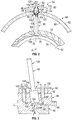
- the compressor section 24 may be provided with a modular variable vane assembly 60.
- the modular variable vane assembly 60 may be an inlet guide vane assembly that is located upstream of a rotor of a stage of at least one of the low pressure compressor 44 or the high pressure compressor 52.
- the modular variable vane assembly 60 extends between an inner case 62 and an outer case 64 of the compressor section 24.
- the inner case 62 is disposed about the central longitudinal axis A of the gas turbine engine 20.
- the inner case 62 may be a portion of an inner shroud.
- the inner case 62 defines a pivot opening 70 that extends from an inner case first surface 72 towards an inner case second surface 74 along an axis 76 that is disposed transverse to the central longitudinal axis A.
- the outer case 64 is spaced apart from the inner case 62 and is disposed about the inner case 62.
- the outer case 64 is further away from axis A than the inner case 62.
- the outer case 64 includes a first outer case surface 80 and a second outer case surface 82.
- the first outer case surface 80 is disposed closer to the inner case 62 than the second outer case surface 82.
- the outer case 64 defines a first opening 84, a first cavity 86, and a first shoulder 88.
- the first opening 84 extends from the first outer case surface 80 towards the second outer case surface 82 along the axis 76.
- the first cavity 86 extends from the second outer case surface 82 towards the first opening 84.
- the first cavity 86 has a cross-sectional form that is greater than the cross-sectional form of the first opening 84.
- the first shoulder 88 extends between ends of the first opening 84 and the first cavity 86.
- the modular variable vane assembly 60 includes an airfoil 90, a drive system 92, and a retainer 94.
- the airfoil 90 radially extends between the inner case 62 and the outer case 64.
- the airfoil 90 radially extends between a first end 100 that is disposed proximate the first outer case surface 80 of the outer case 64 and a second end 102 that is disposed proximate the inner case first surface 72 of the inner case 62 along the axis 76.
- the first end 100 of the airfoil 90 is disposed at a further radial distance from the axis A and the second end 102 of the airfoil 90.
- the airfoil 90 includes a connector 104 and a pivot member 106.
- the connector 104 extends from the first end 100 of the airfoil 90 into the first opening 84 of the outer case 64.
- the connector 104 may be referred to as an outer diameter button.
- the outer diameter button may be integrally formed with the airfoil 90.
- the outer diameter button of the present disclosure has a low profile such that the outer diameter button or connector 104 may be inserted into the first opening 84 of the outer case 64.
- the connector 104 may be a female connector, as illustrated in FIGS. 2 and 3 , or may be a male connector in other arrangements.
- the connector 104 defines a receiving pocket 110 having a pocket floor 112.
- the receiving pocket 110 is arranged to receive at least a portion of the drive system 92.
- the receiving pocket 110 may define a polygon drive interface.
- the pocket floor 112 may be disposed substantially flush with the first outer case surface 80, as shown in FIG. 2 , or may be disposed radially outboard of the first outer case surface 80 such that the pocket floor 112 is radially disposed between the first outer case surface 80 and the second outer case surface 82, as shown in FIG. 3 .
- Such an arrangement moves the drive system 92 away from the flow path that is defined between the outer case 64 and the inner case 62.
- the pivot member 106 extends from the second end 102 of the airfoil 90 and extends into the pivot opening 70 of the inner case 62.
- the pivot member 106 may be referred to as an inner diameter button that may be integrally formed with the airfoil 90.
- the inner diameter button or the pivot member 106 is arranged to facilitate the pivoting of the airfoil 90 about the axis 76.
- the pivot member 106 and the connector 104 are aligned with each other along the axis 76 such that through operation of the drive system 92, the airfoil 90 may be pivoted or rotated about the axis 76.
- the drive system 92 extends at least partially through the outer case 64 and is arranged to pivot the airfoil 90 about the axis 76.
- the drive system 92 includes a trunnion having a trunnion arm 120 and a trunnion head 122 that extends from the trunnion arm 120.
- the trunnion arm 120 extends through an opening that is defined by the retainer 94 along the axis 76.
- the trunnion arm 120 is connected to a transmission or other device that is arranged to rotate the trunnion arm 122 about the axis 76.
- the trunnion head 122 may be an enlarged head having a cross-sectional form that is larger than the trunnion arm 120.
- the trunnion head 122 extends along the axis 76 through the first cavity 86 and into the connector 104.
- a first end of the trunnion head 122 may be disposed generally parallel to the first shoulder 88 of the outer case 64.
- the first end of the trunnion head 122 may be arranged to engage the first shoulder 88 of the outer case 64.
- the trunnion head 122 defines connecting head 124 having a cross-sectional form that is less than the cross-sectional form of the trunnion head 122.
- the connecting head 124 extends into the receiving pocket 110.
- the connecting head 124 may have a mating polygon drive that mates with the polygon drive interface of the receiving pocket 110 of the connector 104 to facilitate the driving of the airfoil 90 about the axis 76.
- the connecting head 124 may act as a male connector that extends into the female connector defined by the connector 104 of the airfoil 90.
- the trunnion head 122 and the connecting head 124 are each spaced apart from and do not extend beyond the first outer case surface 80 towards the inner case 62.
- the retainer 94 is disposed on the second outer case surface 82 of the outer case 64 and is at least partially disposed about the trunnion arm 120 to retain the trunnion head 122 between the retainer 94 and the outer case 64.
- the retainer 94 may be secured to the outer case 64 by fasteners that extend through the retainer 94 and extend into the outer case 64.
- the retainer 94 includes a first retainer surface 130 that engages the second outer case surface 82 and a second retainer surface 132 that is disposed opposite the first retainer surface 130.
- the retainer 94 defines a second opening 140, a second cavity 142, and a second shoulder 144 that extends between the second opening 140 and the second cavity 142.
- the second opening 140 extends from the second retainer surface 132 towards the first retainer surface 130.
- the second cavity 142 extends from the first retainer surface 130 towards the second opening 140.
- the second shoulder 144 extends between ends of the second opening 140 and the second cavity 142.
- a second end of the trunnion head 122 that is disposed opposite the connecting head 124 may be disposed generally parallel to the second shoulder 144 of the retainer 94.
- the second end of the trunnion head 122 may be arranged to engage the second shoulder 144 of the retainer 94.
- the trunnion head 122 is disposed within or extends between the first cavity 86 of the outer case 64 and the second cavity 142 of the retainer 94.
- the connecting head 124 extends beyond the second cavity 142 and extends into the first opening 84 of the outer case 64 such that the connecting head 124 is received within the receiving pocket 110 of the connector 104 of the airfoil 90.
- variable vane assembly enables the trunnion arm 120 and the trunnion head 122 of the drive system 92 to be inserted into the first end 100 of the airfoil 90. This arrangement reduces the complexity of the design and moves the drive system 92 away from the flow path that is defined between the inner case 62 and the outer case 64.
Landscapes
- Engineering & Computer Science (AREA)
- Mechanical Engineering (AREA)
- General Engineering & Computer Science (AREA)
- Structures Of Non-Positive Displacement Pumps (AREA)
Applications Claiming Priority (1)
| Application Number | Priority Date | Filing Date | Title |
|---|---|---|---|
| US16/214,829 US10830087B2 (en) | 2018-12-10 | 2018-12-10 | Modular variable vane assembly |
Publications (2)
| Publication Number | Publication Date |
|---|---|
| EP3667030A1 true EP3667030A1 (de) | 2020-06-17 |
| EP3667030B1 EP3667030B1 (de) | 2023-04-05 |
Family
ID=68848135
Family Applications (1)
| Application Number | Title | Priority Date | Filing Date |
|---|---|---|---|
| EP19214980.5A Active EP3667030B1 (de) | 2018-12-10 | 2019-12-10 | Modulare variable leitschaufelanordnung für einen verdichterabschnitt eines gasturbinentriebwerks |
Country Status (2)
| Country | Link |
|---|---|
| US (1) | US10830087B2 (de) |
| EP (1) | EP3667030B1 (de) |
Citations (4)
| Publication number | Priority date | Publication date | Assignee | Title |
|---|---|---|---|---|
| US20070160464A1 (en) * | 2006-01-06 | 2007-07-12 | Snecma | Anti-wear device for a guide pivot of a variable-pitch vane of a turbomachine compressor |
| EP1892422A1 (de) * | 2006-08-25 | 2008-02-27 | Siemens Aktiengesellschaft | Verdichterleitschauffel für einen Verdichter und Verfahren zum Wiederherstellen eines Verdichters |
| EP2407673A1 (de) * | 2010-07-12 | 2012-01-18 | Siemens Aktiengesellschaft | Verdichter |
| US20140169950A1 (en) * | 2012-12-18 | 2014-06-19 | United Technologies Corporation | Variable vane having body formed of first material and trunnion formed of second material |
Family Cites Families (12)
| Publication number | Priority date | Publication date | Assignee | Title |
|---|---|---|---|---|
| CA1040535A (en) * | 1976-02-09 | 1978-10-17 | Westinghouse Electric Corporation | Variable vane and flowpath support assembly for a gas turbine |
| JPS55114883A (en) * | 1979-02-28 | 1980-09-04 | Toshiba Corp | Side gap adjusting method and device for guide vane |
| FR2583820B1 (fr) * | 1985-06-20 | 1989-04-28 | Snecma | Dispositif de variation de section de passage d'un distributeur de turbine |
| JPH09203371A (ja) * | 1996-01-26 | 1997-08-05 | Hitachi Ltd | 土砂摩耗対応水力機器 |
| US6450763B1 (en) | 2000-11-17 | 2002-09-17 | General Electric Company | Replaceable variable stator vane for gas turbines |
| GB2402179B (en) * | 2003-05-27 | 2006-02-22 | Rolls Royce Plc | A variable vane arrangement for a turbomachine |
| GB0312098D0 (en) * | 2003-05-27 | 2004-05-05 | Rolls Royce Plc | A variable arrangement for a turbomachine |
| US7131815B2 (en) * | 2003-07-11 | 2006-11-07 | Rolls-Royce Plc | Inlet guide vane |
| GB0505147D0 (en) * | 2005-03-12 | 2005-04-20 | Rolls Royce Plc | Securing arrangement |
| US8033785B2 (en) | 2008-09-12 | 2011-10-11 | General Electric Company | Features to properly orient inlet guide vanes |
| US9074489B2 (en) * | 2012-03-26 | 2015-07-07 | Pratt & Whitney Canada Corp. | Connector assembly for variable inlet guide vanes and method |
| US10036282B2 (en) * | 2014-05-28 | 2018-07-31 | United Technologies Corporation | Vane support systems |
-
2018
- 2018-12-10 US US16/214,829 patent/US10830087B2/en active Active
-
2019
- 2019-12-10 EP EP19214980.5A patent/EP3667030B1/de active Active
Patent Citations (4)
| Publication number | Priority date | Publication date | Assignee | Title |
|---|---|---|---|---|
| US20070160464A1 (en) * | 2006-01-06 | 2007-07-12 | Snecma | Anti-wear device for a guide pivot of a variable-pitch vane of a turbomachine compressor |
| EP1892422A1 (de) * | 2006-08-25 | 2008-02-27 | Siemens Aktiengesellschaft | Verdichterleitschauffel für einen Verdichter und Verfahren zum Wiederherstellen eines Verdichters |
| EP2407673A1 (de) * | 2010-07-12 | 2012-01-18 | Siemens Aktiengesellschaft | Verdichter |
| US20140169950A1 (en) * | 2012-12-18 | 2014-06-19 | United Technologies Corporation | Variable vane having body formed of first material and trunnion formed of second material |
Also Published As
| Publication number | Publication date |
|---|---|
| US20200182082A1 (en) | 2020-06-11 |
| EP3667030B1 (de) | 2023-04-05 |
| US10830087B2 (en) | 2020-11-10 |
Similar Documents
| Publication | Publication Date | Title |
|---|---|---|
| US9790861B2 (en) | Gas turbine engine having support structure with swept leading edge | |
| EP2809929B1 (de) | Lüfteraustrittsstator mit hoher drehung | |
| US10370974B2 (en) | Gas turbine engine airfoil | |
| US10358925B2 (en) | Gas turbine engine airfoil | |
| EP3054138A1 (de) | Turboverdichter mit getriebefan | |
| EP3536908A1 (de) | Plattformanordnung für einen fan eines gasturbinenmotors | |
| EP3453830B1 (de) | Turbinenleitschaufelanordnung mit variablem bereich | |
| US11002147B2 (en) | Fixed vane pack retaining ring | |
| US11286797B2 (en) | Gas turbine engine stator vane base shape | |
| EP3670835A1 (de) | Gasturbinenmotorrotorschaufel mit einer lokalen druckseitigen schaufelblattspitzenneigung | |
| EP3667030B1 (de) | Modulare variable leitschaufelanordnung für einen verdichterabschnitt eines gasturbinentriebwerks | |
| EP3896262B1 (de) | Turbinenschaufelkühlöffnung für eine seitenwand | |
| EP3453837B1 (de) | Rückhaltesystem eines statoranordnung eines gebläseaustritts | |
| EP3693544A1 (de) | Tangentialeinspritzdüse einer gasturbine mit durchgehender umlenkdüse | |
| EP3907373B1 (de) | Kühllochkombination für turbinenschaufel | |
| EP3483393A1 (de) | Lüfteranordnung eines gasturbinenmotors mit einem spitzendeckband | |
| EP3919721B1 (de) | Kühlsystem für ein gasturbinentriebwerk | |
| EP3008290B1 (de) | Turbinenschaufel mit variablem austrittskanten-innenradius | |
| EP4495402A1 (de) | Bifurkationsluftschaufel für gasturbinenmotor | |
| EP3715641B1 (de) | Gekerbter axialflansch für einen kompressor mit geteiltem gehäuse | |
| EP3789586A1 (de) | Aerodynamische element-montage für ein gasturbinentriebwerk | |
| EP3428404A1 (de) | Leitschaufelanordnung für einen gasturbinenmotor |
Legal Events
| Date | Code | Title | Description |
|---|---|---|---|
| PUAI | Public reference made under article 153(3) epc to a published international application that has entered the european phase |
Free format text: ORIGINAL CODE: 0009012 |
|
| STAA | Information on the status of an ep patent application or granted ep patent |
Free format text: STATUS: THE APPLICATION HAS BEEN PUBLISHED |
|
| AK | Designated contracting states |
Kind code of ref document: A1 Designated state(s): AL AT BE BG CH CY CZ DE DK EE ES FI FR GB GR HR HU IE IS IT LI LT LU LV MC MK MT NL NO PL PT RO RS SE SI SK SM TR |
|
| AX | Request for extension of the european patent |
Extension state: BA ME |
|
| STAA | Information on the status of an ep patent application or granted ep patent |
Free format text: STATUS: REQUEST FOR EXAMINATION WAS MADE |
|
| 17P | Request for examination filed |
Effective date: 20201216 |
|
| RBV | Designated contracting states (corrected) |
Designated state(s): AL AT BE BG CH CY CZ DE DK EE ES FI FR GB GR HR HU IE IS IT LI LT LU LV MC MK MT NL NO PL PT RO RS SE SI SK SM TR |
|
| STAA | Information on the status of an ep patent application or granted ep patent |
Free format text: STATUS: EXAMINATION IS IN PROGRESS |
|
| 17Q | First examination report despatched |
Effective date: 20210129 |
|
| RAP1 | Party data changed (applicant data changed or rights of an application transferred) |
Owner name: RAYTHEON TECHNOLOGIES CORPORATION |
|
| GRAP | Despatch of communication of intention to grant a patent |
Free format text: ORIGINAL CODE: EPIDOSNIGR1 |
|
| STAA | Information on the status of an ep patent application or granted ep patent |
Free format text: STATUS: GRANT OF PATENT IS INTENDED |
|
| INTG | Intention to grant announced |
Effective date: 20221019 |
|
| GRAS | Grant fee paid |
Free format text: ORIGINAL CODE: EPIDOSNIGR3 |
|
| GRAA | (expected) grant |
Free format text: ORIGINAL CODE: 0009210 |
|
| STAA | Information on the status of an ep patent application or granted ep patent |
Free format text: STATUS: THE PATENT HAS BEEN GRANTED |
|
| AK | Designated contracting states |
Kind code of ref document: B1 Designated state(s): AL AT BE BG CH CY CZ DE DK EE ES FI FR GB GR HR HU IE IS IT LI LT LU LV MC MK MT NL NO PL PT RO RS SE SI SK SM TR |
|
| REG | Reference to a national code |
Ref country code: GB Ref legal event code: FG4D |
|
| REG | Reference to a national code |
Ref country code: CH Ref legal event code: EP |
|
| REG | Reference to a national code |
Ref country code: AT Ref legal event code: REF Ref document number: 1558397 Country of ref document: AT Kind code of ref document: T Effective date: 20230415 |
|
| REG | Reference to a national code |
Ref country code: DE Ref legal event code: R096 Ref document number: 602019027143 Country of ref document: DE |
|
| REG | Reference to a national code |
Ref country code: IE Ref legal event code: FG4D |
|
| P01 | Opt-out of the competence of the unified patent court (upc) registered |
Effective date: 20230521 |
|
| REG | Reference to a national code |
Ref country code: LT Ref legal event code: MG9D |
|
| REG | Reference to a national code |
Ref country code: NL Ref legal event code: MP Effective date: 20230405 |
|
| REG | Reference to a national code |
Ref country code: AT Ref legal event code: MK05 Ref document number: 1558397 Country of ref document: AT Kind code of ref document: T Effective date: 20230405 |
|
| PG25 | Lapsed in a contracting state [announced via postgrant information from national office to epo] |
Ref country code: NL Free format text: LAPSE BECAUSE OF FAILURE TO SUBMIT A TRANSLATION OF THE DESCRIPTION OR TO PAY THE FEE WITHIN THE PRESCRIBED TIME-LIMIT Effective date: 20230405 |
|
| PG25 | Lapsed in a contracting state [announced via postgrant information from national office to epo] |
Ref country code: SE Free format text: LAPSE BECAUSE OF FAILURE TO SUBMIT A TRANSLATION OF THE DESCRIPTION OR TO PAY THE FEE WITHIN THE PRESCRIBED TIME-LIMIT Effective date: 20230405 Ref country code: PT Free format text: LAPSE BECAUSE OF FAILURE TO SUBMIT A TRANSLATION OF THE DESCRIPTION OR TO PAY THE FEE WITHIN THE PRESCRIBED TIME-LIMIT Effective date: 20230807 Ref country code: NO Free format text: LAPSE BECAUSE OF FAILURE TO SUBMIT A TRANSLATION OF THE DESCRIPTION OR TO PAY THE FEE WITHIN THE PRESCRIBED TIME-LIMIT Effective date: 20230705 Ref country code: ES Free format text: LAPSE BECAUSE OF FAILURE TO SUBMIT A TRANSLATION OF THE DESCRIPTION OR TO PAY THE FEE WITHIN THE PRESCRIBED TIME-LIMIT Effective date: 20230405 Ref country code: AT Free format text: LAPSE BECAUSE OF FAILURE TO SUBMIT A TRANSLATION OF THE DESCRIPTION OR TO PAY THE FEE WITHIN THE PRESCRIBED TIME-LIMIT Effective date: 20230405 |
|
| RAP4 | Party data changed (patent owner data changed or rights of a patent transferred) |
Owner name: RTX CORPORATION |
|
| PG25 | Lapsed in a contracting state [announced via postgrant information from national office to epo] |
Ref country code: RS Free format text: LAPSE BECAUSE OF FAILURE TO SUBMIT A TRANSLATION OF THE DESCRIPTION OR TO PAY THE FEE WITHIN THE PRESCRIBED TIME-LIMIT Effective date: 20230405 Ref country code: PL Free format text: LAPSE BECAUSE OF FAILURE TO SUBMIT A TRANSLATION OF THE DESCRIPTION OR TO PAY THE FEE WITHIN THE PRESCRIBED TIME-LIMIT Effective date: 20230405 Ref country code: LV Free format text: LAPSE BECAUSE OF FAILURE TO SUBMIT A TRANSLATION OF THE DESCRIPTION OR TO PAY THE FEE WITHIN THE PRESCRIBED TIME-LIMIT Effective date: 20230405 Ref country code: LT Free format text: LAPSE BECAUSE OF FAILURE TO SUBMIT A TRANSLATION OF THE DESCRIPTION OR TO PAY THE FEE WITHIN THE PRESCRIBED TIME-LIMIT Effective date: 20230405 Ref country code: IS Free format text: LAPSE BECAUSE OF FAILURE TO SUBMIT A TRANSLATION OF THE DESCRIPTION OR TO PAY THE FEE WITHIN THE PRESCRIBED TIME-LIMIT Effective date: 20230805 Ref country code: HR Free format text: LAPSE BECAUSE OF FAILURE TO SUBMIT A TRANSLATION OF THE DESCRIPTION OR TO PAY THE FEE WITHIN THE PRESCRIBED TIME-LIMIT Effective date: 20230405 Ref country code: GR Free format text: LAPSE BECAUSE OF FAILURE TO SUBMIT A TRANSLATION OF THE DESCRIPTION OR TO PAY THE FEE WITHIN THE PRESCRIBED TIME-LIMIT Effective date: 20230706 Ref country code: AL Free format text: LAPSE BECAUSE OF FAILURE TO SUBMIT A TRANSLATION OF THE DESCRIPTION OR TO PAY THE FEE WITHIN THE PRESCRIBED TIME-LIMIT Effective date: 20230405 |
|
| PG25 | Lapsed in a contracting state [announced via postgrant information from national office to epo] |
Ref country code: FI Free format text: LAPSE BECAUSE OF FAILURE TO SUBMIT A TRANSLATION OF THE DESCRIPTION OR TO PAY THE FEE WITHIN THE PRESCRIBED TIME-LIMIT Effective date: 20230405 |
|
| REG | Reference to a national code |
Ref country code: DE Ref legal event code: R097 Ref document number: 602019027143 Country of ref document: DE |
|
| PG25 | Lapsed in a contracting state [announced via postgrant information from national office to epo] |
Ref country code: SK Free format text: LAPSE BECAUSE OF FAILURE TO SUBMIT A TRANSLATION OF THE DESCRIPTION OR TO PAY THE FEE WITHIN THE PRESCRIBED TIME-LIMIT Effective date: 20230405 |
|
| PG25 | Lapsed in a contracting state [announced via postgrant information from national office to epo] |
Ref country code: SM Free format text: LAPSE BECAUSE OF FAILURE TO SUBMIT A TRANSLATION OF THE DESCRIPTION OR TO PAY THE FEE WITHIN THE PRESCRIBED TIME-LIMIT Effective date: 20230405 Ref country code: SK Free format text: LAPSE BECAUSE OF FAILURE TO SUBMIT A TRANSLATION OF THE DESCRIPTION OR TO PAY THE FEE WITHIN THE PRESCRIBED TIME-LIMIT Effective date: 20230405 Ref country code: RO Free format text: LAPSE BECAUSE OF FAILURE TO SUBMIT A TRANSLATION OF THE DESCRIPTION OR TO PAY THE FEE WITHIN THE PRESCRIBED TIME-LIMIT Effective date: 20230405 Ref country code: EE Free format text: LAPSE BECAUSE OF FAILURE TO SUBMIT A TRANSLATION OF THE DESCRIPTION OR TO PAY THE FEE WITHIN THE PRESCRIBED TIME-LIMIT Effective date: 20230405 Ref country code: DK Free format text: LAPSE BECAUSE OF FAILURE TO SUBMIT A TRANSLATION OF THE DESCRIPTION OR TO PAY THE FEE WITHIN THE PRESCRIBED TIME-LIMIT Effective date: 20230405 Ref country code: CZ Free format text: LAPSE BECAUSE OF FAILURE TO SUBMIT A TRANSLATION OF THE DESCRIPTION OR TO PAY THE FEE WITHIN THE PRESCRIBED TIME-LIMIT Effective date: 20230405 |
|
| PLBE | No opposition filed within time limit |
Free format text: ORIGINAL CODE: 0009261 |
|
| STAA | Information on the status of an ep patent application or granted ep patent |
Free format text: STATUS: NO OPPOSITION FILED WITHIN TIME LIMIT |
|
| 26N | No opposition filed |
Effective date: 20240108 |
|
| PG25 | Lapsed in a contracting state [announced via postgrant information from national office to epo] |
Ref country code: SI Free format text: LAPSE BECAUSE OF FAILURE TO SUBMIT A TRANSLATION OF THE DESCRIPTION OR TO PAY THE FEE WITHIN THE PRESCRIBED TIME-LIMIT Effective date: 20230405 |
|
| PG25 | Lapsed in a contracting state [announced via postgrant information from national office to epo] |
Ref country code: SI Free format text: LAPSE BECAUSE OF FAILURE TO SUBMIT A TRANSLATION OF THE DESCRIPTION OR TO PAY THE FEE WITHIN THE PRESCRIBED TIME-LIMIT Effective date: 20230405 Ref country code: IT Free format text: LAPSE BECAUSE OF FAILURE TO SUBMIT A TRANSLATION OF THE DESCRIPTION OR TO PAY THE FEE WITHIN THE PRESCRIBED TIME-LIMIT Effective date: 20230405 |
|
| REG | Reference to a national code |
Ref country code: CH Ref legal event code: PL |
|
| PG25 | Lapsed in a contracting state [announced via postgrant information from national office to epo] |
Ref country code: LU Free format text: LAPSE BECAUSE OF NON-PAYMENT OF DUE FEES Effective date: 20231210 |
|
| PG25 | Lapsed in a contracting state [announced via postgrant information from national office to epo] |
Ref country code: MC Free format text: LAPSE BECAUSE OF FAILURE TO SUBMIT A TRANSLATION OF THE DESCRIPTION OR TO PAY THE FEE WITHIN THE PRESCRIBED TIME-LIMIT Effective date: 20230405 |
|
| REG | Reference to a national code |
Ref country code: BE Ref legal event code: MM Effective date: 20231231 |
|
| PG25 | Lapsed in a contracting state [announced via postgrant information from national office to epo] |
Ref country code: MC Free format text: LAPSE BECAUSE OF FAILURE TO SUBMIT A TRANSLATION OF THE DESCRIPTION OR TO PAY THE FEE WITHIN THE PRESCRIBED TIME-LIMIT Effective date: 20230405 Ref country code: LU Free format text: LAPSE BECAUSE OF NON-PAYMENT OF DUE FEES Effective date: 20231210 |
|
| REG | Reference to a national code |
Ref country code: IE Ref legal event code: MM4A |
|
| PG25 | Lapsed in a contracting state [announced via postgrant information from national office to epo] |
Ref country code: IE Free format text: LAPSE BECAUSE OF NON-PAYMENT OF DUE FEES Effective date: 20231210 |
|
| PG25 | Lapsed in a contracting state [announced via postgrant information from national office to epo] |
Ref country code: BE Free format text: LAPSE BECAUSE OF NON-PAYMENT OF DUE FEES Effective date: 20231231 |
|
| PG25 | Lapsed in a contracting state [announced via postgrant information from national office to epo] |
Ref country code: CH Free format text: LAPSE BECAUSE OF NON-PAYMENT OF DUE FEES Effective date: 20231231 |
|
| PG25 | Lapsed in a contracting state [announced via postgrant information from national office to epo] |
Ref country code: IE Free format text: LAPSE BECAUSE OF NON-PAYMENT OF DUE FEES Effective date: 20231210 Ref country code: CH Free format text: LAPSE BECAUSE OF NON-PAYMENT OF DUE FEES Effective date: 20231231 Ref country code: BE Free format text: LAPSE BECAUSE OF NON-PAYMENT OF DUE FEES Effective date: 20231231 |
|
| PG25 | Lapsed in a contracting state [announced via postgrant information from national office to epo] |
Ref country code: BG Free format text: LAPSE BECAUSE OF FAILURE TO SUBMIT A TRANSLATION OF THE DESCRIPTION OR TO PAY THE FEE WITHIN THE PRESCRIBED TIME-LIMIT Effective date: 20230405 |
|
| PG25 | Lapsed in a contracting state [announced via postgrant information from national office to epo] |
Ref country code: BG Free format text: LAPSE BECAUSE OF FAILURE TO SUBMIT A TRANSLATION OF THE DESCRIPTION OR TO PAY THE FEE WITHIN THE PRESCRIBED TIME-LIMIT Effective date: 20230405 |
|
| PG25 | Lapsed in a contracting state [announced via postgrant information from national office to epo] |
Ref country code: CY Free format text: LAPSE BECAUSE OF FAILURE TO SUBMIT A TRANSLATION OF THE DESCRIPTION OR TO PAY THE FEE WITHIN THE PRESCRIBED TIME-LIMIT; INVALID AB INITIO Effective date: 20191210 |
|
| PG25 | Lapsed in a contracting state [announced via postgrant information from national office to epo] |
Ref country code: HU Free format text: LAPSE BECAUSE OF FAILURE TO SUBMIT A TRANSLATION OF THE DESCRIPTION OR TO PAY THE FEE WITHIN THE PRESCRIBED TIME-LIMIT; INVALID AB INITIO Effective date: 20191210 |
|
| REG | Reference to a national code |
Ref country code: DE Ref legal event code: R081 Ref document number: 602019027143 Country of ref document: DE Owner name: RTX CORPORATION (N.D.GES.D. STAATES DELAWARE),, US Free format text: FORMER OWNER: RAYTHEON TECHNOLOGIES CORPORATION, FARMINGTON, CT, US |
|
| PG25 | Lapsed in a contracting state [announced via postgrant information from national office to epo] |
Ref country code: TR Free format text: LAPSE BECAUSE OF FAILURE TO SUBMIT A TRANSLATION OF THE DESCRIPTION OR TO PAY THE FEE WITHIN THE PRESCRIBED TIME-LIMIT Effective date: 20230405 |
|
| PGFP | Annual fee paid to national office [announced via postgrant information from national office to epo] |
Ref country code: DE Payment date: 20251126 Year of fee payment: 7 |
|
| PGFP | Annual fee paid to national office [announced via postgrant information from national office to epo] |
Ref country code: GB Payment date: 20251119 Year of fee payment: 7 |
|
| PGFP | Annual fee paid to national office [announced via postgrant information from national office to epo] |
Ref country code: FR Payment date: 20251120 Year of fee payment: 7 |