EP3667053A1 - Circuit de carburant d'enrichissement pour un carburateur - Google Patents
Circuit de carburant d'enrichissement pour un carburateur Download PDFInfo
- Publication number
- EP3667053A1 EP3667053A1 EP19215295.7A EP19215295A EP3667053A1 EP 3667053 A1 EP3667053 A1 EP 3667053A1 EP 19215295 A EP19215295 A EP 19215295A EP 3667053 A1 EP3667053 A1 EP 3667053A1
- Authority
- EP
- European Patent Office
- Prior art keywords
- fuel
- air
- carburettor
- nozzle
- bore
- Prior art date
- Legal status (The legal status is an assumption and is not a legal conclusion. Google has not performed a legal analysis and makes no representation as to the accuracy of the status listed.)
- Granted
Links
Images










Classifications
-
- F—MECHANICAL ENGINEERING; LIGHTING; HEATING; WEAPONS; BLASTING
- F02—COMBUSTION ENGINES; HOT-GAS OR COMBUSTION-PRODUCT ENGINE PLANTS
- F02M—SUPPLYING COMBUSTION ENGINES IN GENERAL WITH COMBUSTIBLE MIXTURES OR CONSTITUENTS THEREOF
- F02M1/00—Carburettors with means for facilitating engine's starting or its idling below operational temperatures
- F02M1/04—Carburettors with means for facilitating engine's starting or its idling below operational temperatures the means to facilitate starting or idling being auxiliary carburetting apparatus able to be put into, and out of, operation, e.g. having automatically-operated disc valves
- F02M1/043—Auxiliary carburetting apparatus controlled by rotary sliding valves
-
- F—MECHANICAL ENGINEERING; LIGHTING; HEATING; WEAPONS; BLASTING
- F02—COMBUSTION ENGINES; HOT-GAS OR COMBUSTION-PRODUCT ENGINE PLANTS
- F02M—SUPPLYING COMBUSTION ENGINES IN GENERAL WITH COMBUSTIBLE MIXTURES OR CONSTITUENTS THEREOF
- F02M19/00—Details, component parts, or accessories of carburettors, not provided for in, or of interest apart from, the apparatus of groups F02M1/00 - F02M17/00
- F02M19/03—Fuel atomising nozzles; Arrangement of emulsifying air conduits
-
- F—MECHANICAL ENGINEERING; LIGHTING; HEATING; WEAPONS; BLASTING
- F02—COMBUSTION ENGINES; HOT-GAS OR COMBUSTION-PRODUCT ENGINE PLANTS
- F02M—SUPPLYING COMBUSTION ENGINES IN GENERAL WITH COMBUSTIBLE MIXTURES OR CONSTITUENTS THEREOF
- F02M19/00—Details, component parts, or accessories of carburettors, not provided for in, or of interest apart from, the apparatus of groups F02M1/00 - F02M17/00
- F02M19/12—External control gear, e.g. having dash-pots
-
- F—MECHANICAL ENGINEERING; LIGHTING; HEATING; WEAPONS; BLASTING
- F02—COMBUSTION ENGINES; HOT-GAS OR COMBUSTION-PRODUCT ENGINE PLANTS
- F02M—SUPPLYING COMBUSTION ENGINES IN GENERAL WITH COMBUSTIBLE MIXTURES OR CONSTITUENTS THEREOF
- F02M3/00—Idling devices for carburettors
-
- F—MECHANICAL ENGINEERING; LIGHTING; HEATING; WEAPONS; BLASTING
- F02—COMBUSTION ENGINES; HOT-GAS OR COMBUSTION-PRODUCT ENGINE PLANTS
- F02M—SUPPLYING COMBUSTION ENGINES IN GENERAL WITH COMBUSTIBLE MIXTURES OR CONSTITUENTS THEREOF
- F02M7/00—Carburettors with means for influencing, e.g. enriching or keeping constant, fuel/air ratio of charge under varying conditions
- F02M7/04—Means for enriching charge at high combustion-air flow
-
- F—MECHANICAL ENGINEERING; LIGHTING; HEATING; WEAPONS; BLASTING
- F02—COMBUSTION ENGINES; HOT-GAS OR COMBUSTION-PRODUCT ENGINE PLANTS
- F02M—SUPPLYING COMBUSTION ENGINES IN GENERAL WITH COMBUSTIBLE MIXTURES OR CONSTITUENTS THEREOF
- F02M7/00—Carburettors with means for influencing, e.g. enriching or keeping constant, fuel/air ratio of charge under varying conditions
- F02M7/23—Fuel aerating devices
Definitions
- the present invention relates to a diaphragm carburettor, and in particular to novel arrangements for facilitating fuel flow during acceleration of an engine to which the carburettor is fitted.
- the present invention is especially but not exclusively applicable to a carburettor for supplying fuel to low capacity two-stroke or four-stroke engines designed for use on, for example, chain saws, concrete saws, trimmers, lawn mowers and karts and the like.
- Carburettors are well known devices that function to supply a fuel/air mixture to the one or more cylinders of two-stroke and four-stroke engines.
- acceleration problems due to a carburettor supplying insufficient fuel on acceleration. This conventionally arises from the inertia of moving components within the carburettor, imperfect machining within the carburettor, limitations on the location of components arising from various design and/or cost constraints, as well as elevated temperatures and vibration transmitted from the engine.
- Ultra-lean acceleration will deprive the engine of proper cooling leading to various issues.
- Current designs include a series of progression holes allowing fuel to flow into the throttle bore to mix with the air. This type of arrangement has limitations in terms of the location at which the progress holes can be machined, resulting in acceleration issues.
- Part throttle jets have also been used but again have limitations in relation to the possible location of the jets.
- Angled fuel nozzles have been used to improve acceleration but the delivery of fuel from these nozzles can be quite coarse resulting in the engine hesitating during acceleration due to an over-supply of fuel.
- the present invention has therefore been developed to solve the above problems and is primarily intended to provide a carburettor with the ability to supply an improved mixture of fuel as required from a partially open throttle to a wide open throttle allowing the engine to have stable operation across that throttle range.
- the present invention includes a carburettor which has three fuel circuits, fuel circuit one is an idle fuel circuit which is controlled by an idle adjustment needle for low engine speed, fuel circuit two is an enrichment fuel circuit which takes fuel from a fuel metering chamber and fuel circuit three is a high fuel circuit which is controlled by a high speed needle for maximum engine speed.
- Fuel circuit one supplies fuel to a first nozzle. There is one air circuit that flows air from the throttle bore to the first nozzle. The design of the nozzle allows the air and fuel to mix prior to exiting the nozzle at high velocity resulting in a more complete mixture of air and fuel to form a mist. This premix of air and fuel is released into the throttle bore where further mixing of air occurs. This results in a more accurate supply of air and fuel to the engine during the acceleration modes and wide open throttle.
- a carburettor comprising a throttle bore; a fuel chamber; an idle fuel circuit extending between the fuel chamber and the throttle bore and controllable by an idle adjustment member; a high speed fuel circuit extending between the fuel chamber and the throttle bore and controllable by a high speed adjustment member; and an enrichment fuel circuit extending between the fuel chamber and the throttle bore for supplying fuel to the throttle bore independently of the idle and high speed fuel circuits.
- the idle fuel circuit comprises a first nozzle operable to delivery fuel to the throttle bore.
- the carburettor comprises a first air delivery passage arranged to supply air to the first nozzle.
- the high speed fuel circuit comprises a second nozzle operable to deliver fuel to the throttle bore.
- the carburettor comprises a second air delivery passage arranged to supply air to the second nozzle.
- the enrichment fuel circuit comprises a third nozzle operable to deliver fuel to the throttle bore.
- the carburettor comprises a third air delivery passage arranged to supply air to the third nozzle.
- one or more of the nozzles defines an airflow path arranged to combine air with fuel flowing through the nozzle.
- one or more of the nozzles comprises a fixed jet arranged to control the flow of fuel or air into the nozzle.
- the carburettor comprises a choke bore in communication with the throttle bore, at least one portion of a sidewall of the choke bore being adapted to modify air flow through the choke bore.
- At least one portion of the choke bore sidewall is adapted to rotate about a longitudinal axis of the choke bore in order to modify the airflow.
- the carburettor comprises drive means operable to effect rotation of the at least one portion of choke bore sidewall.
- the choke bore sidewall comprises multiple sidewall portions of different profiles.
- the carburettor comprises a throttle valve operable to regulate air flow through the throttle bore, wherein the throttle valve is in operative association with an enrichment valve operable to regulate delivery of fuel to the fuel enrichment circuit.
- the carburettor comprises a cam displaceable by a throttle valve shaft such as to effect regulation of the delivery of fuel to the fuel enrichment circuit, the cam being operable to displace a shuttle valve between a closed position disabling the fuel enrichment circuit and an open position enabling the fuel enrichment circuit.
- Figure 1 illustrates a body 1 of the diaphragm carburettor of the invention, including a fuel metering chamber 2 formed in an upper portion of the body 1. It will be appreciated that a suitable fuel reservoir in the form of a container may be provided about said upper portion of the body 1 to enclose and further define the fuel metering chamber 2.
- the body 1 has a first air and fuel nozzle 3a that forms part of an idle fuel circuit extending between the fuel-metering chamber 2 and a throttle bore 4 which extends through the interior of the body 1 in conventional fashion.
- the air fuel nozzle 3a is arranged to combine liquid fuel and air to issue as a mist or atomised dispersion of fuel in air, into the throttle bore for onward delivery to one or more cylinders of the associated engine for combustion.
- the carburettor is illustrated in Figure 1 .
- the body 1 also has a second air and fuel nozzle 3b that forms part of a high-speed fuel circuit likewise extending between the fuel-metering chamber 2 and the throttle bore 4.
- the high speed fuel circuit is arranged to supply fuel from the fuel metering chamber 2 to a throat of the throttle bore 4, which will often have a venturi type cross section as illustrated, and again as an atomised dispersion of the liquid fuel in air.
- a third air fuel nozzle 3c is also provided and forms part of an enrichment fuel circuit extending between the fuel-metering chamber 2 and the throttle bore 4 as hereinafter described in greater detail.
- the fuel enrichment circuit is arranged to supply fuel from the fuel metering chamber 2 to the throttle bore 4 at a location upstream of the outlet of the high speed fuel circuit.
- Figure 2 shows a flow path in the form of a transfer journal 5 that is connected to a machined hole 6 that is drilled in to the metering chamber 2. Another connection hole 7 is machined from the transfer journal 5 in to the air and fuel nozzle 3c. The air and fuel nozzle 3c is assembled into the body 1 such as to project into the throttle bore 4 and intersects the connection hole 7. A fuel flow path is therefore defined between the fuel metering chamber 2 and the throttle bore 4 via the hole 6, journal 5, connection hole 7 and the air and fuel nozzle 3c, collectively forming the enrichment fuel circuit.
- the air and fuel nozzle 3c is assembled in to the body 1 by a press fit.
- the press fit ensures that fuel does not leak external to the body 1.
- the air and fuel nozzle 3c could also be threaded in to the body 1 if required, or secured in any other suitable fashion.
- the transfer journal 5 and/or connection hole 7 could also be replaced by external machining or pipework (not shown) outside the body 1, or any other functional alternative, which facilitates fluid communication between the fuel-metering chamber 2 and the air and fuel nozzle 3c.
- Figure 3 shows the air and fuel nozzle 3c in a non-working status. Fuel cannot flow from the metering chamber 2 into the transfer journal 5, the air and fuel nozzle 3c and on to the throttle bore 4. This is due to the absence of a vacuum on the air and fuel nozzle 3c because a throttle valve in the form of a throttle shutter 8 is in the closed position.
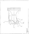
- FIG. 4 shows the air and fuel nozzle 3c in the open working status.
- the throttle shutter 8 now in an opened position the air and fuel nozzle 3c receives a vacuum signal in throttle bore 4. This allows fuel to flow from the metering chamber 2 in to the transfer journal 5, in to the air and fuel nozzle 3c and in to the throttle bore 4.
- the air and fuel nozzle 3c can also pull air from an airflow path in the form of a feedhole 10 extending from the throttle bore 4 to the air and fuel nozzle 3c.
- the quantity of fuel and air entering the air and fuel nozzle 3c is controlled by the feed hole 9 and 10 respectively.
- a jet (not shown) or both a feedhole and jet can control the quantity of fuel and air supplied to the air and fuel nozzle 3c.
- Figure 5 shows a section of the body 1 with the air and fuel nozzle 3c flowing both fuel and air together in to the throttle bore 4 when the throttle shutter 8 is in the opened position.
- Figure 6 shows the direction of fuel flow through the body 1 in to the throttle bore 4.
- Figure 7 illustrates an air nozzle 11 forming part of the air and fuel nozzles 3a, 3b, 3c that has an air entry hole 12 and a air exit hole 13 for the air to flow through.
- the fuel transfer ports 14 show the fuel direction flow.
- Figure 8 is a front elevation of the air nozzle 11 where the fuel transfer ports 14 and the exit hole 13 can be seen in more detail.
- This air nozzle 11 can also be reversed to flow fuel instead of air depending on the application and engine requirements.
- Figure 9 shows a fuel nozzle 15 forming part of the air and fuel nozzles 3a, 3b, 3c with the fuel entry hole 16 and an exit hole 17.
- the fuel nozzle 15 surrounds the air nozzle 11 to form the air and fuel nozzles 3a, 3b, 3c.
- Figure 10 shows the assembly of nozzle 11 and 15 to form the air and fuel nozzles 3a, 3b, 3c.
- Figure 11 shows a cross-section through the diaphragm carburettor body 1 in which the air and fuel nozzles 3a, 3b, 3c have been omitted from the idle fuel circuit, high speed fuel circuit and the enrichment fuel circuit.
- This shows the transfer journal 5 that forms part of the enrichment fuel circuit.
- a hole 18 is machined from the transfer journal 5 in to the metering chamber 2.
- Another hole 9 is machined from the transfer journal 5 in to an air and fuel journal 37 which replaces the air and fuel nozzle 3c.
- the air feedhole 10 is machined or otherwise formed in the body 1 and extending from the throttle bore 4 in to the air and fuel journal 37.
- the air and fuel journal 37 remains independent of both the idle fuel circuit 19 and high speed fuel circuit 20.
- Figure 12 shows a cross-section through the diaphragm carburettor body 1.
- Figure 12 shows the air and fuel nozzle 3c forming part of the fuel enrichment circuit, the air and fuel nozzle 3a forming part of the idle fuel circuit 19, and the air and fuel nozzle 3b forming part of the high speed fuel circuit 20.
- An air feedhole 21 is provided from the throttle bore 4 to supply air to the air and fuel nozzle 3a.
- An air feedhole 22 is provided from a choke bore 40 to supply air to the air and fuel nozzle 3b.
- the choke bore 40 is located upstream of and in communication with the throttle bore 4, and together they define a through passage in the body 1.
- air can be supplied to the respective nozzle 3a, 3b, 3c to mix with the fuel flow through the nozzle in order to generate an atomised dispersion of fuel in the air, which is then supplied to the throttle bore 4 for onward supply and combustion within the cylinder(s) of the engine (not shown).
- Figure 13 shows a further cross-section through the diaphragm carburettor body 1.
- This arrangement illustrates that the air feedholes can be included or removed depending on the engine requirements. In some cases the air and fuel nozzle 3a, 3b, 3c will only require a partial quantity of air so all air feedholes are not required.
- the air and fuel nozzle 3b and 3c have no air feedholes and the air and fuel nozzle 3a has the air feedhole 21.
- This arrangement serves to illustrate that the air and fuel nozzle 3a, 3b, 3c can include and exclude the air feedholes as required.
- Figure 14 shows the enrichment fuel circuit with an assembled jet 23 to control the quantity of fuel flow in to the air and fuel nozzle 3c.
- the assembled jet 23 can be applied to all or some of the air and fuel nozzles 3a, 3b, 3c either through the air or fuel pathway depending on the engine requirements, and the jet 23 can be of conventional form and dimensioned to provide the requisite fuel metering function.
- Figure 15 shows an end elevation of the carburettor according to the invention, as viewed from the choke bore 40 end.
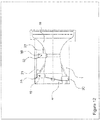
- a sidewall of the choke bore 40 comprises a sidewall profile made up of two different wall profiles 24 and 25 in order to speed up or slow down the velocity of air flowing through the choke bore 40 extending through the body 1. This helps the atomisation of fuel at various part throttles leading to improved acceleration.
- Various surface features, shapes, and/or profiles of the choke bore 40 sidewall may thus be utilised to modify the airflow through the choke bore, such as to for example to generate increased turbulence and therefore mixing of the fuel and air.
- Figure 16 shows a cross-section through the sidewall profile 24.
- Profile 24 is not confined to this shape but can be either regular or irregular in the profile shape and surface finish.
- This profile can be machined or otherwise formed into the body 1 or provided as a separate component to be fitted into the body 1 by any suitable means.
- Figure 17 shows a cross-section through the profile 25.
- Profile 25 is not confined to this shape but can be either regular or irregular in the profile shape and surface finish.
- This profile can be machined into the body 1 or provided as a separate component to be fitted into the body 1 by any suitable means.
- Figure 18 shows the profile 24 assembled onto some form of a bearing 37.
- the bearing 37 is assembled into the body 1. This assemble forms an air gap 38 that allows the profile 24 to rotate with the body 1 about a longitudinal axis of the choke bore 40.
- the bearing 37 can also be applied to the profile 25. The rotation of profile 24 and 25 will speed up the velocity of air entering the carburettor that will allow for better atomisation of the fuel leading to improvement acceleration and power delivery.
- Figure 19 shows the profile 24 with more than one bearing 37a and 37b for additional support. This also applies to profile 25.
- Figure 20 shows the profile 24 connected up to drive means in the form of an electric motor 47 so that the rotation speed of profile 24 can be increased or decrease. This also applies to profile 25.
- the electric motor can be fitted into the body 1 or external to the body 1.
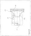
- Figure 21 shows an end view cross-section through the body 1 illustrating the throttle shutter 8 connected between opposed portions of a throttle shaft 26 and 27 in order to allow the shutter 8 to be pivoted between the open and closed positions.
- the throttle shaft 26, 27 is rotated by the throttle lever assembly 28 which determines the positions from closed to open of the throttle shutter 8.
- the throttle lever assembly 28 may be actuated by any suitable means, for example cable actuated or the like.
- Mounted at one end of the throttle shaft 26, 27 is a cam 29 that is in contact with an enrichment valve in the form of a piston 48.
- a spring 31 applies a force on the piston 48 to bias the piston 48 into contact with the cam 29.
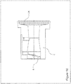
- Figure 22 shows a longitudinal cross-section through the body 1 of the carburettor and showing the same arrangement of features as illustrated in Figure 21 .
- the throttle shutter 8 is in the closed position.
- a journal 30 is machined from the fuel-metering chamber 2 to a piston journal 35.
- a conduit 32 is provided from the piston journal 35 to the air fuel nozzle 3c.
- the piston 48 has two seals 33 and 34. Seal 34 prevents fuel from flowing into the conduit 32 while the throttle shutter 8 is in the closed position as the cam 29 is arranged to position the piston 38 such that the seal 34 is upstream of and thus blocking access to the conduit 32..
- Figure 23 shows a cross-section through the body 1.
- the throttle shutter 8 is in the opened position. As the throttle shutter 8 starts the cam 29 rotates and this action displaces the piston 48 against the bias of the spring 31. The seal 34 is therefore displaced beyond the conduit 32 and now allows fuel to flow from the piston journal 35 to the air fuel nozzle 3c through the conduit 32.
- the cam 29 can be calibrated to deliver fuel to the engine with more precision through the range of throttle shutter 8 positions and engine rpm.
- air and fuel nozzle 3c can also be a standard nozzle or a machined exit hole or any other suitable functional form operable to deliver fuel. In this way position dependent fuel enrichment can be implemented and linked to throttle position, or more particularly to the position of the throttle shutter 8.
- Figure 24 shows in detail the piston 48 and its seal 33 and 34 which each comprises a captured O-ring but can be of any other suitable form.
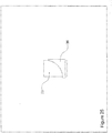
- FIG. 25 shows in detail the cam 29.
- Cam 29 has a cam profile 36 that is used to move the piston 48.
- Cam profile 36 can be adjusted to different shapes in order to deliver the correct quantity of fuel to the engine for calibration. Note the cam is an example but some other form of mechanism can be used to move the piston.
Landscapes
- Engineering & Computer Science (AREA)
- Chemical & Material Sciences (AREA)
- Combustion & Propulsion (AREA)
- Mechanical Engineering (AREA)
- General Engineering & Computer Science (AREA)
- Control Of The Air-Fuel Ratio Of Carburetors (AREA)
Applications Claiming Priority (1)
| Application Number | Priority Date | Filing Date | Title |
|---|---|---|---|
| IES20180565 | 2018-12-11 |
Publications (3)
| Publication Number | Publication Date |
|---|---|
| EP3667053A1 true EP3667053A1 (fr) | 2020-06-17 |
| EP3667053C0 EP3667053C0 (fr) | 2024-01-24 |
| EP3667053B1 EP3667053B1 (fr) | 2024-01-24 |
Family
ID=89433483
Family Applications (1)
| Application Number | Title | Priority Date | Filing Date |
|---|---|---|---|
| EP19215295.7A Active EP3667053B1 (fr) | 2018-12-11 | 2019-12-11 | Circuit de carburant d'enrichissement pour un carburateur |
Country Status (2)
| Country | Link |
|---|---|
| EP (1) | EP3667053B1 (fr) |
| IE (1) | IES87109Y1 (fr) |
Citations (6)
| Publication number | Priority date | Publication date | Assignee | Title |
|---|---|---|---|---|
| BE337997A (fr) * | 1925-11-11 | 1926-12-28 | Carburateur reglable | |
| US1895470A (en) * | 1929-04-30 | 1933-01-31 | Mathieu Eugene | Carburetor |
| US1984327A (en) * | 1930-09-17 | 1934-12-11 | Detroit Lubricator Co | Carburetor |
| GB1281218A (en) * | 1968-08-09 | 1972-07-12 | Acf Ind Inc | Carburettors for internal combustion engines |
| US4329964A (en) * | 1978-03-17 | 1982-05-18 | Morris George Q | Liquid fuel carburetion system |
| US4411233A (en) * | 1980-07-17 | 1983-10-25 | Societe Industrielle De Brevets Et D'etudes S.I.B.E. | Carburation devices for internal combustion engines |
-
2019
- 2019-12-10 IE IE20190222A patent/IES87109Y1/en unknown
- 2019-12-11 EP EP19215295.7A patent/EP3667053B1/fr active Active
Patent Citations (6)
| Publication number | Priority date | Publication date | Assignee | Title |
|---|---|---|---|---|
| BE337997A (fr) * | 1925-11-11 | 1926-12-28 | Carburateur reglable | |
| US1895470A (en) * | 1929-04-30 | 1933-01-31 | Mathieu Eugene | Carburetor |
| US1984327A (en) * | 1930-09-17 | 1934-12-11 | Detroit Lubricator Co | Carburetor |
| GB1281218A (en) * | 1968-08-09 | 1972-07-12 | Acf Ind Inc | Carburettors for internal combustion engines |
| US4329964A (en) * | 1978-03-17 | 1982-05-18 | Morris George Q | Liquid fuel carburetion system |
| US4411233A (en) * | 1980-07-17 | 1983-10-25 | Societe Industrielle De Brevets Et D'etudes S.I.B.E. | Carburation devices for internal combustion engines |
Also Published As
| Publication number | Publication date |
|---|---|
| EP3667053C0 (fr) | 2024-01-24 |
| IE20190222U1 (en) | 2020-06-10 |
| EP3667053B1 (fr) | 2024-01-24 |
| IES87109Y1 (en) | 2020-06-10 |
Similar Documents
| Publication | Publication Date | Title |
|---|---|---|
| US6585235B2 (en) | Fuel regulating mechanism and method for a rotary throttle valve type carburetor | |
| US5709822A (en) | Fuel regulating mechanism for a rotary throttle valve type carburetor | |
| US5386145A (en) | Fuel delivery means for carburetors for internal combustion engines and method for installing same | |
| IES87109B2 (en) | Enrichment fuel circuit for a carburettor | |
| IES20190222A2 (en) | Enrichment fuel circuit for a carburettor | |
| EP3667053B1 (fr) | Circuit de carburant d'enrichissement pour un carburateur | |
| US6123322A (en) | Single screw carburetor | |
| JP2004225694A (ja) | 2サイクルエンジンおよびその作動方法 | |
| US5128071A (en) | Carburetor | |
| US10415508B2 (en) | Charge forming device with air bleed control valve | |
| US7028993B2 (en) | Charge forming apparatus | |
| CN105464841B (zh) | 化油器 | |
| US4404151A (en) | Down-draft carburetor | |
| DE60034549T2 (de) | Brennkraftmaschine mit Vergaser mit Leerlaufkanalanordnung | |
| JP4511068B2 (ja) | ベンチュリーピストン及びそれを用いた可変ベンチュリー型キャブレター | |
| US6164631A (en) | Carburetor with elliptical venturi | |
| US1262243A (en) | Carbureter. | |
| US6715738B1 (en) | Fuel-air mixture control apparatus | |
| US6234457B1 (en) | Method of operating a diaphragm-type carburetor | |
| US2065582A (en) | Charge forming device | |
| US20030168753A1 (en) | Carburetor with idle fuel supply arrangement | |
| JPH06336955A (ja) | エンジンの燃料調量装置 | |
| JP2605532B2 (ja) | 可変ベンチュリ型キャブレタ | |
| JP2006189043A (ja) | キャブレータ及びその製作方法 | |
| JPH07293343A (ja) | ダイアフラム式キャブレター |
Legal Events
| Date | Code | Title | Description |
|---|---|---|---|
| PUAI | Public reference made under article 153(3) epc to a published international application that has entered the european phase |
Free format text: ORIGINAL CODE: 0009012 |
|
| STAA | Information on the status of an ep patent application or granted ep patent |
Free format text: STATUS: THE APPLICATION HAS BEEN PUBLISHED |
|
| AK | Designated contracting states |
Kind code of ref document: A1 Designated state(s): AL AT BE BG CH CY CZ DE DK EE ES FI FR GB GR HR HU IE IS IT LI LT LU LV MC MK MT NL NO PL PT RO RS SE SI SK SM TR |
|
| AX | Request for extension of the european patent |
Extension state: BA ME |
|
| STAA | Information on the status of an ep patent application or granted ep patent |
Free format text: STATUS: REQUEST FOR EXAMINATION WAS MADE |
|
| 17P | Request for examination filed |
Effective date: 20201216 |
|
| RBV | Designated contracting states (corrected) |
Designated state(s): AL AT BE BG CH CY CZ DE DK EE ES FI FR GB GR HR HU IE IS IT LI LT LU LV MC MK MT NL NO PL PT RO RS SE SI SK SM TR |
|
| STAA | Information on the status of an ep patent application or granted ep patent |
Free format text: STATUS: EXAMINATION IS IN PROGRESS |
|
| 17Q | First examination report despatched |
Effective date: 20210520 |
|
| GRAP | Despatch of communication of intention to grant a patent |
Free format text: ORIGINAL CODE: EPIDOSNIGR1 |
|
| STAA | Information on the status of an ep patent application or granted ep patent |
Free format text: STATUS: GRANT OF PATENT IS INTENDED |
|
| INTG | Intention to grant announced |
Effective date: 20230926 |
|
| GRAS | Grant fee paid |
Free format text: ORIGINAL CODE: EPIDOSNIGR3 |
|
| GRAA | (expected) grant |
Free format text: ORIGINAL CODE: 0009210 |
|
| STAA | Information on the status of an ep patent application or granted ep patent |
Free format text: STATUS: THE PATENT HAS BEEN GRANTED |
|
| AK | Designated contracting states |
Kind code of ref document: B1 Designated state(s): AL AT BE BG CH CY CZ DE DK EE ES FI FR GB GR HR HU IE IS IT LI LT LU LV MC MK MT NL NO PL PT RO RS SE SI SK SM TR |
|
| REG | Reference to a national code |
Ref country code: GB Ref legal event code: FG4D |
|
| REG | Reference to a national code |
Ref country code: CH Ref legal event code: EP |
|
| REG | Reference to a national code |
Ref country code: IE Ref legal event code: FG4D |
|
| REG | Reference to a national code |
Ref country code: DE Ref legal event code: R096 Ref document number: 602019045508 Country of ref document: DE |
|
| U01 | Request for unitary effect filed |
Effective date: 20240206 |
|
| U07 | Unitary effect registered |
Designated state(s): AT BE BG DE DK EE FI FR IT LT LU LV MT NL PT SE SI Effective date: 20240214 |
|
| PG25 | Lapsed in a contracting state [announced via postgrant information from national office to epo] |
Ref country code: IS Free format text: LAPSE BECAUSE OF FAILURE TO SUBMIT A TRANSLATION OF THE DESCRIPTION OR TO PAY THE FEE WITHIN THE PRESCRIBED TIME-LIMIT Effective date: 20240524 |
|
| PG25 | Lapsed in a contracting state [announced via postgrant information from national office to epo] |
Ref country code: GR Free format text: LAPSE BECAUSE OF FAILURE TO SUBMIT A TRANSLATION OF THE DESCRIPTION OR TO PAY THE FEE WITHIN THE PRESCRIBED TIME-LIMIT Effective date: 20240425 |
|
| PG25 | Lapsed in a contracting state [announced via postgrant information from national office to epo] |
Ref country code: HR Free format text: LAPSE BECAUSE OF FAILURE TO SUBMIT A TRANSLATION OF THE DESCRIPTION OR TO PAY THE FEE WITHIN THE PRESCRIBED TIME-LIMIT Effective date: 20240124 Ref country code: RS Free format text: LAPSE BECAUSE OF FAILURE TO SUBMIT A TRANSLATION OF THE DESCRIPTION OR TO PAY THE FEE WITHIN THE PRESCRIBED TIME-LIMIT Effective date: 20240424 |
|
| PG25 | Lapsed in a contracting state [announced via postgrant information from national office to epo] |
Ref country code: ES Free format text: LAPSE BECAUSE OF FAILURE TO SUBMIT A TRANSLATION OF THE DESCRIPTION OR TO PAY THE FEE WITHIN THE PRESCRIBED TIME-LIMIT Effective date: 20240124 |
|
| PG25 | Lapsed in a contracting state [announced via postgrant information from national office to epo] |
Ref country code: RS Free format text: LAPSE BECAUSE OF FAILURE TO SUBMIT A TRANSLATION OF THE DESCRIPTION OR TO PAY THE FEE WITHIN THE PRESCRIBED TIME-LIMIT Effective date: 20240424 Ref country code: NO Free format text: LAPSE BECAUSE OF FAILURE TO SUBMIT A TRANSLATION OF THE DESCRIPTION OR TO PAY THE FEE WITHIN THE PRESCRIBED TIME-LIMIT Effective date: 20240424 Ref country code: IS Free format text: LAPSE BECAUSE OF FAILURE TO SUBMIT A TRANSLATION OF THE DESCRIPTION OR TO PAY THE FEE WITHIN THE PRESCRIBED TIME-LIMIT Effective date: 20240524 Ref country code: HR Free format text: LAPSE BECAUSE OF FAILURE TO SUBMIT A TRANSLATION OF THE DESCRIPTION OR TO PAY THE FEE WITHIN THE PRESCRIBED TIME-LIMIT Effective date: 20240124 Ref country code: GR Free format text: LAPSE BECAUSE OF FAILURE TO SUBMIT A TRANSLATION OF THE DESCRIPTION OR TO PAY THE FEE WITHIN THE PRESCRIBED TIME-LIMIT Effective date: 20240425 Ref country code: ES Free format text: LAPSE BECAUSE OF FAILURE TO SUBMIT A TRANSLATION OF THE DESCRIPTION OR TO PAY THE FEE WITHIN THE PRESCRIBED TIME-LIMIT Effective date: 20240124 |
|
| PG25 | Lapsed in a contracting state [announced via postgrant information from national office to epo] |
Ref country code: PL Free format text: LAPSE BECAUSE OF FAILURE TO SUBMIT A TRANSLATION OF THE DESCRIPTION OR TO PAY THE FEE WITHIN THE PRESCRIBED TIME-LIMIT Effective date: 20240124 |
|
| PG25 | Lapsed in a contracting state [announced via postgrant information from national office to epo] |
Ref country code: PL Free format text: LAPSE BECAUSE OF FAILURE TO SUBMIT A TRANSLATION OF THE DESCRIPTION OR TO PAY THE FEE WITHIN THE PRESCRIBED TIME-LIMIT Effective date: 20240124 |
|
| PG25 | Lapsed in a contracting state [announced via postgrant information from national office to epo] |
Ref country code: SM Free format text: LAPSE BECAUSE OF FAILURE TO SUBMIT A TRANSLATION OF THE DESCRIPTION OR TO PAY THE FEE WITHIN THE PRESCRIBED TIME-LIMIT Effective date: 20240124 |
|
| PG25 | Lapsed in a contracting state [announced via postgrant information from national office to epo] |
Ref country code: CZ Free format text: LAPSE BECAUSE OF FAILURE TO SUBMIT A TRANSLATION OF THE DESCRIPTION OR TO PAY THE FEE WITHIN THE PRESCRIBED TIME-LIMIT Effective date: 20240124 |
|
| REG | Reference to a national code |
Ref country code: DE Ref legal event code: R097 Ref document number: 602019045508 Country of ref document: DE |
|
| PG25 | Lapsed in a contracting state [announced via postgrant information from national office to epo] |
Ref country code: SK Free format text: LAPSE BECAUSE OF FAILURE TO SUBMIT A TRANSLATION OF THE DESCRIPTION OR TO PAY THE FEE WITHIN THE PRESCRIBED TIME-LIMIT Effective date: 20240124 |
|
| PG25 | Lapsed in a contracting state [announced via postgrant information from national office to epo] |
Ref country code: SM Free format text: LAPSE BECAUSE OF FAILURE TO SUBMIT A TRANSLATION OF THE DESCRIPTION OR TO PAY THE FEE WITHIN THE PRESCRIBED TIME-LIMIT Effective date: 20240124 Ref country code: SK Free format text: LAPSE BECAUSE OF FAILURE TO SUBMIT A TRANSLATION OF THE DESCRIPTION OR TO PAY THE FEE WITHIN THE PRESCRIBED TIME-LIMIT Effective date: 20240124 Ref country code: RO Free format text: LAPSE BECAUSE OF FAILURE TO SUBMIT A TRANSLATION OF THE DESCRIPTION OR TO PAY THE FEE WITHIN THE PRESCRIBED TIME-LIMIT Effective date: 20240124 Ref country code: CZ Free format text: LAPSE BECAUSE OF FAILURE TO SUBMIT A TRANSLATION OF THE DESCRIPTION OR TO PAY THE FEE WITHIN THE PRESCRIBED TIME-LIMIT Effective date: 20240124 |
|
| PLBE | No opposition filed within time limit |
Free format text: ORIGINAL CODE: 0009261 |
|
| STAA | Information on the status of an ep patent application or granted ep patent |
Free format text: STATUS: NO OPPOSITION FILED WITHIN TIME LIMIT |
|
| U20 | Renewal fee for the european patent with unitary effect paid |
Year of fee payment: 6 Effective date: 20241108 |
|
| 26N | No opposition filed |
Effective date: 20241025 |
|
| PG25 | Lapsed in a contracting state [announced via postgrant information from national office to epo] |
Ref country code: MC Free format text: LAPSE BECAUSE OF FAILURE TO SUBMIT A TRANSLATION OF THE DESCRIPTION OR TO PAY THE FEE WITHIN THE PRESCRIBED TIME-LIMIT Effective date: 20240124 |
|
| REG | Reference to a national code |
Ref country code: CH Ref legal event code: PL |
|
| GBPC | Gb: european patent ceased through non-payment of renewal fee |
Effective date: 20241211 |
|
| PG25 | Lapsed in a contracting state [announced via postgrant information from national office to epo] |
Ref country code: GB Free format text: LAPSE BECAUSE OF NON-PAYMENT OF DUE FEES Effective date: 20241211 |
|
| PG25 | Lapsed in a contracting state [announced via postgrant information from national office to epo] |
Ref country code: CH Free format text: LAPSE BECAUSE OF NON-PAYMENT OF DUE FEES Effective date: 20241231 |
|
| PG25 | Lapsed in a contracting state [announced via postgrant information from national office to epo] |
Ref country code: IE Free format text: LAPSE BECAUSE OF NON-PAYMENT OF DUE FEES Effective date: 20241211 |
|
| U20 | Renewal fee for the european patent with unitary effect paid |
Year of fee payment: 7 Effective date: 20251117 |