EP3667148B1 - Compensateur de longueur - Google Patents
Compensateur de longueur Download PDFInfo
- Publication number
- EP3667148B1 EP3667148B1 EP19163711.5A EP19163711A EP3667148B1 EP 3667148 B1 EP3667148 B1 EP 3667148B1 EP 19163711 A EP19163711 A EP 19163711A EP 3667148 B1 EP3667148 B1 EP 3667148B1
- Authority
- EP
- European Patent Office
- Prior art keywords
- compensating element
- length compensator
- friction
- lateral surface
- length
- Prior art date
- Legal status (The legal status is an assumption and is not a legal conclusion. Google has not performed a legal analysis and makes no representation as to the accuracy of the status listed.)
- Active
Links
Images

Classifications
-
- F—MECHANICAL ENGINEERING; LIGHTING; HEATING; WEAPONS; BLASTING
- F16—ENGINEERING ELEMENTS AND UNITS; GENERAL MEASURES FOR PRODUCING AND MAINTAINING EFFECTIVE FUNCTIONING OF MACHINES OR INSTALLATIONS; THERMAL INSULATION IN GENERAL
- F16L—PIPES; JOINTS OR FITTINGS FOR PIPES; SUPPORTS FOR PIPES, CABLES OR PROTECTIVE TUBING; MEANS FOR THERMAL INSULATION IN GENERAL
- F16L47/00—Connecting arrangements or other fittings specially adapted to be made of plastics or to be used with pipes made of plastics
- F16L47/04—Connecting arrangements or other fittings specially adapted to be made of plastics or to be used with pipes made of plastics with a swivel nut or collar engaging the pipe
-
- F—MECHANICAL ENGINEERING; LIGHTING; HEATING; WEAPONS; BLASTING
- F16—ENGINEERING ELEMENTS AND UNITS; GENERAL MEASURES FOR PRODUCING AND MAINTAINING EFFECTIVE FUNCTIONING OF MACHINES OR INSTALLATIONS; THERMAL INSULATION IN GENERAL
- F16L—PIPES; JOINTS OR FITTINGS FOR PIPES; SUPPORTS FOR PIPES, CABLES OR PROTECTIVE TUBING; MEANS FOR THERMAL INSULATION IN GENERAL
- F16L51/00—Expansion-compensation arrangements for pipe-lines
- F16L51/02—Expansion-compensation arrangements for pipe-lines making use of a bellows or an expansible folded or corrugated tube
- F16L51/025—Expansion-compensation arrangements for pipe-lines making use of a bellows or an expansible folded or corrugated tube with several corrugations
-
- F—MECHANICAL ENGINEERING; LIGHTING; HEATING; WEAPONS; BLASTING
- F16—ENGINEERING ELEMENTS AND UNITS; GENERAL MEASURES FOR PRODUCING AND MAINTAINING EFFECTIVE FUNCTIONING OF MACHINES OR INSTALLATIONS; THERMAL INSULATION IN GENERAL
- F16L—PIPES; JOINTS OR FITTINGS FOR PIPES; SUPPORTS FOR PIPES, CABLES OR PROTECTIVE TUBING; MEANS FOR THERMAL INSULATION IN GENERAL
- F16L51/00—Expansion-compensation arrangements for pipe-lines
-
- F—MECHANICAL ENGINEERING; LIGHTING; HEATING; WEAPONS; BLASTING
- F16—ENGINEERING ELEMENTS AND UNITS; GENERAL MEASURES FOR PRODUCING AND MAINTAINING EFFECTIVE FUNCTIONING OF MACHINES OR INSTALLATIONS; THERMAL INSULATION IN GENERAL
- F16L—PIPES; JOINTS OR FITTINGS FOR PIPES; SUPPORTS FOR PIPES, CABLES OR PROTECTIVE TUBING; MEANS FOR THERMAL INSULATION IN GENERAL
- F16L13/00—Non-disconnectable pipe joints, e.g. soldered, adhesive, or caulked joints
- F16L13/02—Welded joints
-
- F—MECHANICAL ENGINEERING; LIGHTING; HEATING; WEAPONS; BLASTING
- F16—ENGINEERING ELEMENTS AND UNITS; GENERAL MEASURES FOR PRODUCING AND MAINTAINING EFFECTIVE FUNCTIONING OF MACHINES OR INSTALLATIONS; THERMAL INSULATION IN GENERAL
- F16L—PIPES; JOINTS OR FITTINGS FOR PIPES; SUPPORTS FOR PIPES, CABLES OR PROTECTIVE TUBING; MEANS FOR THERMAL INSULATION IN GENERAL
- F16L13/00—Non-disconnectable pipe joints, e.g. soldered, adhesive, or caulked joints
- F16L13/10—Adhesive or cemented joints
-
- F—MECHANICAL ENGINEERING; LIGHTING; HEATING; WEAPONS; BLASTING
- F16—ENGINEERING ELEMENTS AND UNITS; GENERAL MEASURES FOR PRODUCING AND MAINTAINING EFFECTIVE FUNCTIONING OF MACHINES OR INSTALLATIONS; THERMAL INSULATION IN GENERAL
- F16L—PIPES; JOINTS OR FITTINGS FOR PIPES; SUPPORTS FOR PIPES, CABLES OR PROTECTIVE TUBING; MEANS FOR THERMAL INSULATION IN GENERAL
- F16L27/00—Adjustable joints; Joints allowing movement
- F16L27/10—Adjustable joints; Joints allowing movement comprising a flexible connection only
- F16L27/107—Adjustable joints; Joints allowing movement comprising a flexible connection only the ends of the pipe being interconnected by a flexible sleeve
-
- F—MECHANICAL ENGINEERING; LIGHTING; HEATING; WEAPONS; BLASTING
- F16—ENGINEERING ELEMENTS AND UNITS; GENERAL MEASURES FOR PRODUCING AND MAINTAINING EFFECTIVE FUNCTIONING OF MACHINES OR INSTALLATIONS; THERMAL INSULATION IN GENERAL
- F16L—PIPES; JOINTS OR FITTINGS FOR PIPES; SUPPORTS FOR PIPES, CABLES OR PROTECTIVE TUBING; MEANS FOR THERMAL INSULATION IN GENERAL
- F16L33/00—Arrangements for connecting hoses to rigid members; Rigid hose-connectors, i.e. single members engaging both hoses
- F16L33/006—Arrangements for connecting hoses to rigid members; Rigid hose-connectors, i.e. single members engaging both hoses for hoses of plastics other than artificial rubber
-
- F—MECHANICAL ENGINEERING; LIGHTING; HEATING; WEAPONS; BLASTING
- F16—ENGINEERING ELEMENTS AND UNITS; GENERAL MEASURES FOR PRODUCING AND MAINTAINING EFFECTIVE FUNCTIONING OF MACHINES OR INSTALLATIONS; THERMAL INSULATION IN GENERAL
- F16L—PIPES; JOINTS OR FITTINGS FOR PIPES; SUPPORTS FOR PIPES, CABLES OR PROTECTIVE TUBING; MEANS FOR THERMAL INSULATION IN GENERAL
- F16L33/00—Arrangements for connecting hoses to rigid members; Rigid hose-connectors, i.e. single members engaging both hoses
- F16L33/34—Arrangements for connecting hoses to rigid members; Rigid hose-connectors, i.e. single members engaging both hoses with bonding obtained by vulcanisation, gluing, melting, or the like
Definitions
- the invention relates to a length compensator for pipelines, preferably plastic pipelines containing two connection components made of plastic, a compensation element made of an elastic material and a support tube, the compensation element being arranged between the two connection components and the compensation element ends being connected to the connection components.
- Length compensators are used to absorb or compensate for changes in the length of an installed pipeline, for example due to temperature changes or external influences such as forces from earthquakes, pump surges, etc.
- the length of a pipeline changes depending on the temperature, whether due to the outside temperature or the temperature of the medium in the pipeline transported medium. This change in length, be it expansion or contraction, needs to be accommodated.
- Pipe loops for example, are known from the prior art, which allow or absorb a certain change in length due to their deflections of the pipeline.
- bellows or rubber sleeves as well as tubes that can be displaced axially into one another are also known from the prior art.
- German utility model 7325208 discloses an expansion compensator for pipelines, the expansion body being arranged in a housing which
- the document U.S. 2015/273756 A1 discloses a method of making an expansion compensator, the method comprising: (a) providing an inner plastic liner having spaced apart first and second ends, an inner surface, an outer surface, and an interior volume differing from the first end extends to the second end; (b) positioning the inner plastic liner inside an elongate metal conduit, the elongate metal conduit having first and second spaced ends, an inner surface, an outer surface, and an expansion/contraction section; (c) applying pressure to a fluid located within the interior volume of the inner plastic liner while the inner plastic liner is at or above a molding temperature to expand the inner plastic liner, thereby the expanded plastic inner liner has an expansion/contraction section; and (d) cooling the inner plastic liner to a temperature below the molding temperature.
- the expansion compensator can be provided with a sleeve.
- the sleeve can cover the entire expansion/contraction section.
- Connectors can be provided at opposite ends of the metal tube and plastic liner.
- the connectors can be formed by overmolding portions of the connector onto the ends of the metal tube and inner plastic liner. Alternatively, connecting portions of the connectors can be attached to the inner plastic liner, for example by welding.
- the outer jacket surface of the compensating element should have a low frictional resistance to enable a simple change in length of the length compensator.
- this object is achieved by a length compensator according to claim 1 .
- the outer lateral surface of the compensating element is suitably encompassed by the inner lateral surface of the support tube over the entire circumference, the support tube having a round cross-sectional area and the compensating element expanding and contracting exclusively in the axial direction.
- the round cross-sectional area of the support tube preferably extends over the entire length of the support tube, with the cross-sectional area preferably being constant over the entire length.
- the length compensator according to the invention for pipelines contains two connection components made of plastic.
- the connection components are aligned coaxially with one another and preferably have the same inner and outer diameter.
- the length compensator has a compensating element made of an elastic material made of a thermoplastic elastomer (TPE), whereby the compensating element can be formed by a simple elastic hose or a pipe or by an element specially developed for this purpose, which absorbs the change in length of a pipeline.
- TPE thermoplastic elastomer
- the length compensator also has a support tube in which the compensating element is arranged. The compensating element is arranged between the two connection components. The compensating element or the compensating element ends are connected to the connection components.
- the outer lateral surface of the compensating element is suitably encompassed by the inner lateral surface of the support tube over the entire circumference, which means that the compensating element is preferably arranged concentrically in the support tube.
- This arrangement and shape of the compensating element and the support tube means that the compensating element can only expand and contract in the axial direction. Because the support tube surrounds the compensating element or its circumference, the internal pressure is absorbed by the support tube and the compensating element is not overstressed since it is supported by the support tube.
- the connection components are preferably also at least partially surrounded by the support tube or arranged in the support tube, this serves to guide the connection components. It is advantageous if the connection components are also arranged concentrically in or on the support tube.
- connection component is preferably fixed axially on or with the support tube, as a result of which the change in length is adjusted by the displacement of the other connection component and the contraction or expansion of the compensating element.
- connection components are preferably made of polyethylene (PE), but also polypropylene (PP), polybutene (PB), polyvinylidene fluoride (PVDF), polyvinyl chloride (PVC), acrylonitrile butadiene styrene (ABS) or ethylene chlorotrifluoroethylene (ECTFE) and other typical ones Plastic piping materials can be used.
- PE polyethylene
- PP polypropylene
- PB polybutene
- PVDF polyvinylidene fluoride
- PVDF polyvinyl chloride
- ABS acrylonitrile butadiene styrene
- ECTFE ethylene chlorotrifluoroethylene
- connection components are connected to the respective compensating element end by means of an integral connection, namely by means of a butt weld, particularly preferably with a WNF weld, a socket weld, or an electric socket weld.
- Welding can be carried out by means of contact welding as well as a non-contact welding process, preferably IR welding.
- the connecting components and the compensating element can be connected to one another in two-component injection molding and a connecting component is molded onto each of the compensating element ends by means of plastic injection molding. This ensures economical production of the length compensator according to the invention and also the tightness between the compensating element and the connection components.
- connection components is connected to the respective end of the compensation element. This enables a simple, stable and, above all, tight connection between the compensating element and the connecting component.
- connection components are connected to the respective end of the compensating element by means of a positive and/or non-positive connection.
- the compensating element preferably has the same inner diameter as the connection components, this ensures a low flow resistance at the inner diameter, which is beneficial to the medium and to minimizing contamination that accumulates at protruding edges and corners.
- the length compensator according to the invention has a friction-reducing layer; the friction-reducing layer is preferably arranged on the outer lateral surface of the compensating element. This ensures low resistance, which means that changes in the length of the pipeline in the length compensator are easily adjusted or absorbed there. In addition, this ensures that the length compensator represents the lowest resistance in the pipeline and the change in position is compensated for there so that the pipeline does not bend or otherwise move unintentionally.
- the connecting components also have a friction-reducing layer on their outer lateral surface, analogous to the layers used in the support tube or compensating element.
- the support tube is preferably made of a plastic, POM, PE-UHMW, PTFE, MoS 2 polyethylene (PE), polypropylene (PP), polybutene (PB), polyvinylidene fluoride (PVDF), polyvinyl chloride (PVC), acrylonitrile butadiene being particularly preferred -Styrene (ABS) or Ethylene ChloroTriFluoroEthylene (ECTFE) these plastics have good dry lubricating properties.
- POM polypropylene
- PB polybutene
- PVDF polyvinylidene fluoride
- PVDF polyvinyl chloride
- ABS acrylonitrile butadiene
- ABS -Styrene
- ECTFE Ethylene ChloroTriFluoroEthylene
- the friction-reducing layer is formed by a fat or oil, in particular PTFE or silicone. This is quick and easy to apply to the length compensator or the corresponding lateral surface and significantly reduces the frictional resistance between the compensating element and the support tube.
- the friction-reducing layer is formed by dry lubrication, in particular a coating of the inner lateral surface of the support tube, preferably by an anti-friction paint or a metal coating. This enables maintenance-free use of the length compensator.
- a preferred embodiment of the length compensator according to the invention is that the friction-reducing layer is formed by rings or a fabric, with the friction-reducing layer forming the outer lateral surface of the compensating element. It is advantageous if the rings or the fabric are arranged coaxially with the compensating element as well as with the support tube and are fitted between the compensating element and the support tube.
- the longitudinal compensator according to the invention preferably has a stop element, with the stop element being arranged at one end of the support tube.
- the stop element serves to ensure that the length compensator or the compensating element is not overstretched and only maximum expansion is permitted.
- the stop element preferably has a seal on the again ensures the tightness of the lengthening compensator and protects against dirt from outside.
- a further configuration option has been found when the support tube is surrounded by an insulating layer. Above all, this has the advantage with insulated or pre-insulated pipeline systems that the length compensator built into the pipeline also has an insulation layer and does not have to be insulated separately. Due to the fact that the support tube does not change and the compensation takes place inside the support tube, an insulation layer can be attached to the outer circumference of the support tube or other layers, covers or attachments can be provided.
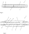
- the drawing shown shows a length compensator 1 according to the invention in a possible embodiment in longitudinal section.
- the length compensator 1 is used to record or compensate for the change in length of a pipeline, which is caused by temperature changes, for example.
- the length compensator 1 has two connection components 2 which are fastened between the opposite free ends of a pipeline.
- the two opposite end faces of the connection components 2 in the support tube 4 are connected to one another by means of a compensation element 3 at the compensation element ends 8, with alternative connection options also being conceivable.
- the connections are preferably inseparable and are produced, for example, by a material connection, such as welding or by means of an injection molding process, which ensures that the connection is tight.
- the ends of the compensating elements 8 are overmoulded and the connection components 2 are formed, although other types of connection are also conceivable, such as positive and/or non-positive connections, as in 3 shown.
- the compensating element 3 is surrounded by the support tube 4 and the connecting component 2 is at least partially surrounded by the support tube 4 . Because the compensating element 3 is suitably surrounded by the support tube 4, it serves to support it and absorbs the internal pressure that is generated by the medium. Due to the surrounding support tube 4, the compensating element 3 cannot expand radially. The compensating element 3 expands and contracts only in the axial direction, whereby the change in length of the pipeline is compensated for and the length compensator 1 nevertheless also withstands the required internal pressure according to the pipeline specification.
- an insulated length compensator 1 As a further embodiment shows 2 an insulated length compensator 1.
- the support tube 4 suitably encloses the compensating element 3 and that expansion and contraction are only possible in the axial direction.
- an insulation layer 5 is arranged on the outer circumference of the support tube 4. This possible embodiment is used in insulated pipeline systems and, in addition to the length compensation of the pipeline system, ensures rapid installation without subsequently attaching separate insulation to the length compensator.
- connection component 2 a possible connection from the length compensator 1 or the connection components 2 to the pipeline is also shown, whereby this can also be implemented for length compensators without an insulation layer.
- a coupling 6 is attached directly to a connection component 2, this being designed here as an electrofusion sleeve, but other couplings are also conceivable.
- the electrofusion socket is welded directly to the connection component 2 on one side and to the pipeline on the other side.
- the connection component 2 is welded to a connection piece 7 on the end face, preferably by means of WNF welding or another material connection technique. And this connecting piece 7 is then in turn connected to a coupling 6, here again an electrofusion sleeve 6.
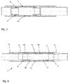
- a length compensator 1 In 3 an alternative embodiment of a length compensator 1 is shown.
- the compensating element ends 8 are fastened to the connection components 2 by means of a positive and non-positive connection 9 .
- a clamp is used, but other known connection techniques can also be used for this purpose.
- connection component 2 which are connected as already mentioned via a material, positive and / or frictional connection.
- One of the connection components 2 is preferably fixed firmly to the support tube 4 or axially to the support tube 4, so that the length compensator 1 or the connection component 2 only moves axially on one side.
- the length compensator 1 has a stop element 11 on the opposite side of the connection component 2 fixed to the support tube 4 .
- the inner cylindrical hollow body 31 can be seen, which is preferably made of an elastic material, preferably a plastic.
- a spiral-shaped element 33 is arranged on its outer lateral surface 32, which forms a friction-reducing layer through its outer lateral surface in order to have the lowest possible resistance to the inner lateral surface of the support tube.
- the spiral-shaped element 33 is preferably made of a plastic.
- the latter has a profile 34 on its outer lateral surface 32 .
- the profiling 34 is preferably designed as a web running in a spiral shape along the outer lateral surface 32 of the cylindrical hollow body 31 .
- the cylindrical hollow body 31 preferably has an increase in wall thickness towards the end faces. This ensures a broader distribution of the tension that occurs when the train is pulled and ensures that there is a connection between the compensating element or the cylindrical hollow body 31 and the connection components 2 that can withstand higher loads. In 6 the cylindrical hollow body 31 is shown separately.
- the compensating element 3 can be produced by the separate production of the cylindrical hollow body 31 and the separate production of the spiral-shaped element 33 and subsequent assembly by mounting the spiral-shaped element 33 onto the cylindrical hollow body 31 or screwing it on or by a two-component injection molding, in which the cylindrical hollow body 31 and the spiral-shaped element 33 are pointed together and thus an assembly process of the two components can be saved.
- a material connection can also be created between the two components in addition to a positive and non-positive connection.
Landscapes
- General Engineering & Computer Science (AREA)
- Engineering & Computer Science (AREA)
- Mechanical Engineering (AREA)
- Rigid Pipes And Flexible Pipes (AREA)
- Lining Or Joining Of Plastics Or The Like (AREA)
- Joints Allowing Movement (AREA)
- Thermal Insulation (AREA)
- Injection Moulding Of Plastics Or The Like (AREA)
- Moulds For Moulding Plastics Or The Like (AREA)
- Supports For Pipes And Cables (AREA)
- Undergarments, Swaddling Clothes, Handkerchiefs Or Underwear Materials (AREA)
- Forklifts And Lifting Vehicles (AREA)
- Axle Suspensions And Sidecars For Cycles (AREA)
Claims (7)
- Compensateur de longueur (1) destiné à des canalisations, de préférence des canalisations en matière synthétique, contenant deux composants de raccordement (2) en matière synthétique, un élément de compensation (3) en matériau élastique en élastomère thermoplastique (TPE), et un tube de support (4), l'élément de compensation (3) étant disposé entre les deux composants de raccordement (2) et les extrémités d'élément de compensation (8) étant reliées aux composants de raccordement (2), la surface latérale extérieure de l'élément de compensation (3) étant entourée de manière ajustée par la surface latérale intérieure du tube de support (4) sur toute la circonférence, le tube de support (4) ayant une section transversale ronde et l'élément de compensation (3) se dilatant et se contractant exclusivement dans la direction axiale, les composants de raccordement (2) étant reliés à l'extrémité respective (8) de l'élément de compensation au moyen d'une liaison de matière, à savoir au moyen d'une soudure bout à bout, de manière particulièrement préférée avec une soudure sans cordon ni rainure, une soudure par raccord ou une soudure par raccord électrique, ou les composants de raccordement (2) et l'élément de compensation étant reliés l'un à l'autre par moulage par injection à deux composants et un composant de raccordement étant moulé sur les extrémités de l'élément de compensation (3).
- Compensateur de longueur (1) selon la revendication 1, caractérisé en ce que les composants de raccordement (2) sont reliés à l'extrémité respective (8) de l'élément de compensation au moyen d'une liaison par complémentarité de formes et/ou en force.
- Compensateur de longueur (1) selon l'une des revendications précédentes, caractérisé en ce qu'une couche de réduction de frottement est disposée sur la surface latérale extérieure de l'élément de compensation (3), de préférence la couche de réduction de frottement est formée par une graisse ou une huile, notamment du PTFE ou du silicone.
- Compensateur de longueur (i) selon la revendication 3, caractérisé en ce que la couche de réduction de frottement est formée par lubrification à sec, notamment d'un revêtement de la surface latérale intérieure du tube de support (4), de préférence par un vernis de glissement ou un revêtement métallique.
- Compensateur de longueur selon l'une des revendications 3 ou 4, caractérisé en ce que la couche de réduction de frottement est formée par des anneaux ou un tissu, la couche de réduction de frottement formant la surface latérale extérieure de l'élément de compensation.
- Compensateur de longueur (1) selon l'une des revendications 1 à 5, caractérisé en ce que le compensateur de longueur (1) comporte un élément de butée (11), l'élément de butée (11) étant disposé à une extrémité du tube de support (4).
- Compensateur de longueur (1) selon l'une des revendications 1 à 6, caractérisé en ce que le tube de support (4) est entouré d'une couche isolante.
Priority Applications (5)
| Application Number | Priority Date | Filing Date | Title |
|---|---|---|---|
| CA3063648A CA3063648A1 (fr) | 2018-12-13 | 2019-12-03 | Compensateur de longueur |
| KR1020190160508A KR102717937B1 (ko) | 2018-12-13 | 2019-12-05 | 길이 보상기 |
| JP2019223629A JP7479140B2 (ja) | 2018-12-13 | 2019-12-11 | 長さ補償器 |
| US16/710,749 US11598469B2 (en) | 2018-12-13 | 2019-12-11 | Length compensator |
| CN201911285600.6A CN111322482B (zh) | 2018-12-13 | 2019-12-13 | 长度补偿器 |
Applications Claiming Priority (1)
| Application Number | Priority Date | Filing Date | Title |
|---|---|---|---|
| EP18212137 | 2018-12-13 |
Publications (2)
| Publication Number | Publication Date |
|---|---|
| EP3667148A1 EP3667148A1 (fr) | 2020-06-17 |
| EP3667148B1 true EP3667148B1 (fr) | 2022-10-19 |
Family
ID=64665232
Family Applications (1)
| Application Number | Title | Priority Date | Filing Date |
|---|---|---|---|
| EP19163711.5A Active EP3667148B1 (fr) | 2018-12-13 | 2019-03-19 | Compensateur de longueur |
Country Status (11)
| Country | Link |
|---|---|
| US (1) | US11598469B2 (fr) |
| EP (1) | EP3667148B1 (fr) |
| JP (1) | JP7479140B2 (fr) |
| KR (1) | KR102717937B1 (fr) |
| CN (1) | CN111322482B (fr) |
| CA (1) | CA3063648A1 (fr) |
| DK (1) | DK3667148T3 (fr) |
| ES (1) | ES2930261T3 (fr) |
| FI (1) | FI3667148T3 (fr) |
| PL (1) | PL3667148T3 (fr) |
| PT (1) | PT3667148T (fr) |
Families Citing this family (4)
| Publication number | Priority date | Publication date | Assignee | Title |
|---|---|---|---|---|
| CN112483757B (zh) * | 2020-12-11 | 2022-09-16 | 焦作万瑞工贸有限公司 | 一种波纹管补偿器 |
| CN114001215B (zh) * | 2021-12-30 | 2022-04-08 | 中国空气动力研究与发展中心设备设计与测试技术研究所 | 一种隔振密封装置 |
| CN115654232B (zh) * | 2022-11-09 | 2025-10-28 | 江苏新核合金科技有限公司 | 一种耐腐蚀合金无缝管及其加工方法 |
| CN116951203A (zh) * | 2023-09-11 | 2023-10-27 | 中国空气动力研究与发展中心设备设计与测试技术研究所 | 一种用于高温流体管道的热变形补偿装置 |
Family Cites Families (34)
| Publication number | Priority date | Publication date | Assignee | Title |
|---|---|---|---|---|
| GB1246055A (en) * | 1969-05-20 | 1971-09-15 | Hepworth Iron Co Ltd | Improvements in or relating to pipe couplings |
| DE7325208U (de) * | 1973-07-09 | 1973-10-25 | Ahlborn E Ag | Dehnungsausgleicher für Rohrleitungen |
| FR2287005A1 (fr) * | 1974-10-01 | 1976-04-30 | Scient Tech Batimen Centre | Manchon de dilatation pour tubes |
| AT353067B (de) * | 1978-04-10 | 1979-10-25 | Straub Immanuel | Rohrkupplung zum verbinden von laengenaenderungen unterworfenen rohren |
| US4225143A (en) * | 1978-06-19 | 1980-09-30 | Advanced Thermal Systems, Inc. | Guided expansion joint |
| JPS57160485U (fr) * | 1981-03-23 | 1982-10-08 | ||
| JPS59125690U (ja) * | 1983-02-14 | 1984-08-24 | 石川島播磨重工業株式会社 | 低温真空二重管 |
| DE3611208A1 (de) * | 1986-04-04 | 1987-10-08 | Haefele Carl Heinz | Leitungskompensator |
| KR960005125U (ko) * | 1994-07-06 | 1996-02-16 | 이창규 | 양말 편직기용 캠뭉치의 전자석 장착장치 |
| DE29701625U1 (de) * | 1997-01-31 | 1997-03-20 | Witzenmann GmbH Metallschlauch-Fabrik Pforzheim, 75175 Pforzheim | Flexibles Leitungselement für Abgasleitungen |
| DE19706191A1 (de) * | 1997-02-18 | 1998-08-20 | Witzenmann Metallschlauchfab | Gelenkiges Verbindungselement für Rohrteile |
| JP4027472B2 (ja) * | 1997-08-18 | 2007-12-26 | アロン化成株式会社 | 管継手 |
| CN2491487Y (zh) * | 2001-08-29 | 2002-05-15 | 宁波波尔新型建材开发有限公司 | 膨胀补偿器 |
| CN2748742Y (zh) * | 2004-12-02 | 2005-12-28 | 赵铎 | 埋地可维护套筒补偿器 |
| JP2006292095A (ja) * | 2005-04-12 | 2006-10-26 | Toyo Tire & Rubber Co Ltd | 高圧ゴムホース |
| EP1741968A1 (fr) * | 2005-07-08 | 2007-01-10 | Uponor Innovation Ab | Bague de serrage |
| DE102007043944A1 (de) * | 2007-09-14 | 2009-03-19 | Westfalia Metallschlauchtechnik Gmbh & Co. Kg | Flexibles Leitungselement mit kombinierter Wärmeisolation und Schwingungsdämpfung |
| CN201723898U (zh) * | 2010-02-10 | 2011-01-26 | 陈墅庚 | 复合型双向补偿器 |
| CN201851831U (zh) * | 2010-11-17 | 2011-06-01 | 陈墅庚 | 新型管道用耐腐蚀伸缩器 |
| US9435473B2 (en) * | 2011-05-04 | 2016-09-06 | Thomas & Betts International, Llc | Non-metallic expansion/deflection coupling modules |
| KR101936731B1 (ko) * | 2011-08-01 | 2019-01-11 | 코웨이 주식회사 | 커넥터 및 배관 연결 구조 |
| NL2010032C2 (nl) * | 2012-12-20 | 2014-06-23 | Trelleborg Ede B V | Expansievat. |
| US9976469B2 (en) * | 2013-07-15 | 2018-05-22 | Thermal Structures, Inc. | Flexible insulation device |
| ES2671939T3 (es) | 2013-07-23 | 2018-06-11 | Georg Fischer Rohrleitungssysteme Ag | Silleta para una conexión de bifurcación |
| US10046510B2 (en) * | 2014-03-25 | 2018-08-14 | Omachron Intellectual Property Inc. | Methods of manufacturing an expansion compensator |
| CA2855326A1 (fr) * | 2014-06-26 | 2015-12-26 | G.B.D. Corp. | Methodes d'installation de compensateur de dilatation |
| US10514115B2 (en) * | 2015-05-28 | 2019-12-24 | Mitsubishi Electric Corporation | Flexible tube |
| US10267447B2 (en) * | 2015-08-12 | 2019-04-23 | Harris Corporation | Fluid pipe assembly including length compensator and related methods |
| CN105090666A (zh) * | 2015-08-25 | 2015-11-25 | 江苏华能输送设备有限公司 | 直管压力平衡型双向补偿波纹补偿器 |
| PL3213890T3 (pl) | 2016-03-01 | 2025-03-24 | Georg Fischer Rohrleitungssysteme Ag | Narzędzie odzierające i tnące |
| ES2986550T3 (es) | 2017-10-11 | 2024-11-11 | Fischer G Rohrleitungssysteme Ag | Método y dispositivo para pelar conductos preaislados |
| EP3550291A1 (fr) | 2018-04-05 | 2019-10-09 | Georg Fischer Rohrleitungssysteme AG | Dispositif de fixation pour appareils de mesure sur des tubes |
| EP3550256B1 (fr) | 2018-04-05 | 2021-03-10 | Georg Fischer Rohrleitungssysteme AG | Détection d'une géométrie du cordon de soudure |
| CN108869934A (zh) * | 2018-06-20 | 2018-11-23 | 朱海军 | 金属软管补偿器的软管结构 |
-
2019
- 2019-03-19 PT PT191637115T patent/PT3667148T/pt unknown
- 2019-03-19 PL PL19163711.5T patent/PL3667148T3/pl unknown
- 2019-03-19 DK DK19163711.5T patent/DK3667148T3/da active
- 2019-03-19 EP EP19163711.5A patent/EP3667148B1/fr active Active
- 2019-03-19 FI FIEP19163711.5T patent/FI3667148T3/fi active
- 2019-03-19 ES ES19163711T patent/ES2930261T3/es active Active
- 2019-12-03 CA CA3063648A patent/CA3063648A1/fr active Pending
- 2019-12-05 KR KR1020190160508A patent/KR102717937B1/ko active Active
- 2019-12-11 JP JP2019223629A patent/JP7479140B2/ja active Active
- 2019-12-11 US US16/710,749 patent/US11598469B2/en active Active
- 2019-12-13 CN CN201911285600.6A patent/CN111322482B/zh active Active
Also Published As
| Publication number | Publication date |
|---|---|
| FI3667148T3 (fi) | 2023-01-31 |
| KR20200074007A (ko) | 2020-06-24 |
| PT3667148T (pt) | 2022-11-03 |
| EP3667148A1 (fr) | 2020-06-17 |
| DK3667148T3 (da) | 2022-11-28 |
| CA3063648A1 (fr) | 2020-06-13 |
| US20200191304A1 (en) | 2020-06-18 |
| KR102717937B1 (ko) | 2024-10-15 |
| JP2020094692A (ja) | 2020-06-18 |
| JP7479140B2 (ja) | 2024-05-08 |
| CN111322482B (zh) | 2023-03-10 |
| US11598469B2 (en) | 2023-03-07 |
| ES2930261T3 (es) | 2022-12-09 |
| PL3667148T3 (pl) | 2023-02-20 |
| CN111322482A (zh) | 2020-06-23 |
Similar Documents
| Publication | Publication Date | Title |
|---|---|---|
| EP3667148B1 (fr) | Compensateur de longueur | |
| EP2677224B1 (fr) | Liaison de serrage pour tuyaux | |
| EP2893241B1 (fr) | Raccord, système muni d'un tel raccord et liaison étanche au moyen d'un tel raccord | |
| DE3808383A1 (de) | Leitungsverbindung | |
| EP3244119B1 (fr) | Élement d'etancheite | |
| EP3940281B1 (fr) | Manchon de tuyau | |
| EP3404305A1 (fr) | Dispositif de raccordement pour conduits fluidiques | |
| EP2295842B1 (fr) | Raccord de tuyau destiné à raccorder de manière étanche une extrémité d'un tuyau en matière flexible | |
| EP4077999B1 (fr) | Raccord enfichable et ensemble raccord enfichable | |
| EP1199536A2 (fr) | Echangeur de chaleur, notamment pour piscines | |
| EP0926417A2 (fr) | Raccord de serrage pour tubes ondulés | |
| WO2019229164A1 (fr) | Adaptateur de raccord de fluide, système de raccord de fluide ainsi que procédé de fabrication d'un système de raccord de fluide | |
| EP2042797B1 (fr) | Agencement de raccordement pour tuyaux d'enroulement | |
| DE102016116652A1 (de) | Hybridfitting zum Anschluss an ein Ende eines Rohres | |
| EP4332420B1 (fr) | Conduite de fluide dotée d'un tube ondulé acheminant le fluide | |
| EP2930411B1 (fr) | Élément de liaison de tubes | |
| CH696082A5 (de) | Verbindungselement für die Verbindung zweier Rohrenden, insbesondere zweier Abwasserrohre. | |
| DE202012003173U1 (de) | Formteil mit mindestens einer Steckmuffe aus Kunststoff sowie mit einer ringförmigen Lippendichtung und Rohrverbindungsanordnung mit einem solchen Formteil | |
| DE19960650C1 (de) | Rohrleitung mit Anschlußstück | |
| DE102016015301A1 (de) | Leitungsvorrichtung für ein Kraftfahrzeug | |
| DE102016007834A1 (de) | Leitungsverbindungsstruktur | |
| WO2018185189A1 (fr) | Garniture d'étanchéité pour tube | |
| DE102024100232A1 (de) | Anschlussset für Wärme- und/oder Kälteerzeuger, insbesondere Wärmepumpen, sowie Mehrfachrohrsystem | |
| EP1617124A1 (fr) | Tuyau, élément d'égout ou regard et procédé de fabrication relatif | |
| DE202021104281U1 (de) | Abdeckvorrichtung zum Abdecken einer Verbindungsstelle von medienführenden Rohrendabschnitten |
Legal Events
| Date | Code | Title | Description |
|---|---|---|---|
| PUAI | Public reference made under article 153(3) epc to a published international application that has entered the european phase |
Free format text: ORIGINAL CODE: 0009012 |
|
| STAA | Information on the status of an ep patent application or granted ep patent |
Free format text: STATUS: THE APPLICATION HAS BEEN PUBLISHED |
|
| AK | Designated contracting states |
Kind code of ref document: A1 Designated state(s): AL AT BE BG CH CY CZ DE DK EE ES FI FR GB GR HR HU IE IS IT LI LT LU LV MC MK MT NL NO PL PT RO RS SE SI SK SM TR |
|
| AX | Request for extension of the european patent |
Extension state: BA ME |
|
| STAA | Information on the status of an ep patent application or granted ep patent |
Free format text: STATUS: REQUEST FOR EXAMINATION WAS MADE |
|
| 17P | Request for examination filed |
Effective date: 20201127 |
|
| RBV | Designated contracting states (corrected) |
Designated state(s): AL AT BE BG CH CY CZ DE DK EE ES FI FR GB GR HR HU IE IS IT LI LT LU LV MC MK MT NL NO PL PT RO RS SE SI SK SM TR |
|
| GRAP | Despatch of communication of intention to grant a patent |
Free format text: ORIGINAL CODE: EPIDOSNIGR1 |
|
| STAA | Information on the status of an ep patent application or granted ep patent |
Free format text: STATUS: GRANT OF PATENT IS INTENDED |
|
| INTG | Intention to grant announced |
Effective date: 20220513 |
|
| GRAS | Grant fee paid |
Free format text: ORIGINAL CODE: EPIDOSNIGR3 |
|
| GRAA | (expected) grant |
Free format text: ORIGINAL CODE: 0009210 |
|
| STAA | Information on the status of an ep patent application or granted ep patent |
Free format text: STATUS: THE PATENT HAS BEEN GRANTED |
|
| AK | Designated contracting states |
Kind code of ref document: B1 Designated state(s): AL AT BE BG CH CY CZ DE DK EE ES FI FR GB GR HR HU IE IS IT LI LT LU LV MC MK MT NL NO PL PT RO RS SE SI SK SM TR |
|
| REG | Reference to a national code |
Ref country code: GB Ref legal event code: FG4D Free format text: NOT ENGLISH |
|
| REG | Reference to a national code |
Ref country code: CH Ref legal event code: EP |
|
| REG | Reference to a national code |
Ref country code: PT Ref legal event code: SC4A Ref document number: 3667148 Country of ref document: PT Date of ref document: 20221103 Kind code of ref document: T Free format text: AVAILABILITY OF NATIONAL TRANSLATION Effective date: 20221027 |
|
| REG | Reference to a national code |
Ref country code: IE Ref legal event code: FG4D Free format text: LANGUAGE OF EP DOCUMENT: GERMAN |
|
| REG | Reference to a national code |
Ref country code: DE Ref legal event code: R096 Ref document number: 502019005945 Country of ref document: DE |
|
| REG | Reference to a national code |
Ref country code: AT Ref legal event code: REF Ref document number: 1525742 Country of ref document: AT Kind code of ref document: T Effective date: 20221115 |
|
| REG | Reference to a national code |
Ref country code: SE Ref legal event code: TRGR |
|
| REG | Reference to a national code |
Ref country code: DK Ref legal event code: T3 Effective date: 20221123 |
|
| REG | Reference to a national code |
Ref country code: NL Ref legal event code: FP |
|
| REG | Reference to a national code |
Ref country code: ES Ref legal event code: FG2A Ref document number: 2930261 Country of ref document: ES Kind code of ref document: T3 Effective date: 20221209 |
|
| REG | Reference to a national code |
Ref country code: NO Ref legal event code: T2 Effective date: 20221019 |
|
| REG | Reference to a national code |
Ref country code: FI Ref legal event code: FGE |
|
| REG | Reference to a national code |
Ref country code: LT Ref legal event code: MG9D |
|
| PG25 | Lapsed in a contracting state [announced via postgrant information from national office to epo] |
Ref country code: LT Free format text: LAPSE BECAUSE OF FAILURE TO SUBMIT A TRANSLATION OF THE DESCRIPTION OR TO PAY THE FEE WITHIN THE PRESCRIBED TIME-LIMIT Effective date: 20221019 |
|
| PG25 | Lapsed in a contracting state [announced via postgrant information from national office to epo] |
Ref country code: RS Free format text: LAPSE BECAUSE OF FAILURE TO SUBMIT A TRANSLATION OF THE DESCRIPTION OR TO PAY THE FEE WITHIN THE PRESCRIBED TIME-LIMIT Effective date: 20221019 Ref country code: LV Free format text: LAPSE BECAUSE OF FAILURE TO SUBMIT A TRANSLATION OF THE DESCRIPTION OR TO PAY THE FEE WITHIN THE PRESCRIBED TIME-LIMIT Effective date: 20221019 Ref country code: IS Free format text: LAPSE BECAUSE OF FAILURE TO SUBMIT A TRANSLATION OF THE DESCRIPTION OR TO PAY THE FEE WITHIN THE PRESCRIBED TIME-LIMIT Effective date: 20230219 Ref country code: HR Free format text: LAPSE BECAUSE OF FAILURE TO SUBMIT A TRANSLATION OF THE DESCRIPTION OR TO PAY THE FEE WITHIN THE PRESCRIBED TIME-LIMIT Effective date: 20221019 Ref country code: GR Free format text: LAPSE BECAUSE OF FAILURE TO SUBMIT A TRANSLATION OF THE DESCRIPTION OR TO PAY THE FEE WITHIN THE PRESCRIBED TIME-LIMIT Effective date: 20230120 |
|
| P01 | Opt-out of the competence of the unified patent court (upc) registered |
Effective date: 20230529 |
|
| REG | Reference to a national code |
Ref country code: DE Ref legal event code: R097 Ref document number: 502019005945 Country of ref document: DE |
|
| PG25 | Lapsed in a contracting state [announced via postgrant information from national office to epo] |
Ref country code: SM Free format text: LAPSE BECAUSE OF FAILURE TO SUBMIT A TRANSLATION OF THE DESCRIPTION OR TO PAY THE FEE WITHIN THE PRESCRIBED TIME-LIMIT Effective date: 20221019 Ref country code: RO Free format text: LAPSE BECAUSE OF FAILURE TO SUBMIT A TRANSLATION OF THE DESCRIPTION OR TO PAY THE FEE WITHIN THE PRESCRIBED TIME-LIMIT Effective date: 20221019 Ref country code: EE Free format text: LAPSE BECAUSE OF FAILURE TO SUBMIT A TRANSLATION OF THE DESCRIPTION OR TO PAY THE FEE WITHIN THE PRESCRIBED TIME-LIMIT Effective date: 20221019 Ref country code: CZ Free format text: LAPSE BECAUSE OF FAILURE TO SUBMIT A TRANSLATION OF THE DESCRIPTION OR TO PAY THE FEE WITHIN THE PRESCRIBED TIME-LIMIT Effective date: 20221019 |
|
| PLBE | No opposition filed within time limit |
Free format text: ORIGINAL CODE: 0009261 |
|
| STAA | Information on the status of an ep patent application or granted ep patent |
Free format text: STATUS: NO OPPOSITION FILED WITHIN TIME LIMIT |
|
| PG25 | Lapsed in a contracting state [announced via postgrant information from national office to epo] |
Ref country code: SK Free format text: LAPSE BECAUSE OF FAILURE TO SUBMIT A TRANSLATION OF THE DESCRIPTION OR TO PAY THE FEE WITHIN THE PRESCRIBED TIME-LIMIT Effective date: 20221019 Ref country code: AL Free format text: LAPSE BECAUSE OF FAILURE TO SUBMIT A TRANSLATION OF THE DESCRIPTION OR TO PAY THE FEE WITHIN THE PRESCRIBED TIME-LIMIT Effective date: 20221019 |
|
| 26N | No opposition filed |
Effective date: 20230720 |
|
| PG25 | Lapsed in a contracting state [announced via postgrant information from national office to epo] |
Ref country code: MC Free format text: LAPSE BECAUSE OF FAILURE TO SUBMIT A TRANSLATION OF THE DESCRIPTION OR TO PAY THE FEE WITHIN THE PRESCRIBED TIME-LIMIT Effective date: 20221019 |
|
| PG25 | Lapsed in a contracting state [announced via postgrant information from national office to epo] |
Ref country code: SI Free format text: LAPSE BECAUSE OF FAILURE TO SUBMIT A TRANSLATION OF THE DESCRIPTION OR TO PAY THE FEE WITHIN THE PRESCRIBED TIME-LIMIT Effective date: 20221019 |
|
| PG25 | Lapsed in a contracting state [announced via postgrant information from national office to epo] |
Ref country code: LU Free format text: LAPSE BECAUSE OF NON-PAYMENT OF DUE FEES Effective date: 20230319 |
|
| PG25 | Lapsed in a contracting state [announced via postgrant information from national office to epo] |
Ref country code: BG Free format text: LAPSE BECAUSE OF FAILURE TO SUBMIT A TRANSLATION OF THE DESCRIPTION OR TO PAY THE FEE WITHIN THE PRESCRIBED TIME-LIMIT Effective date: 20221019 |
|
| PG25 | Lapsed in a contracting state [announced via postgrant information from national office to epo] |
Ref country code: BG Free format text: LAPSE BECAUSE OF FAILURE TO SUBMIT A TRANSLATION OF THE DESCRIPTION OR TO PAY THE FEE WITHIN THE PRESCRIBED TIME-LIMIT Effective date: 20221019 |
|
| PGFP | Annual fee paid to national office [announced via postgrant information from national office to epo] |
Ref country code: ES Payment date: 20250429 Year of fee payment: 7 |
|
| PGFP | Annual fee paid to national office [announced via postgrant information from national office to epo] |
Ref country code: CH Payment date: 20250401 Year of fee payment: 7 |
|
| PG25 | Lapsed in a contracting state [announced via postgrant information from national office to epo] |
Ref country code: CY Free format text: LAPSE BECAUSE OF FAILURE TO SUBMIT A TRANSLATION OF THE DESCRIPTION OR TO PAY THE FEE WITHIN THE PRESCRIBED TIME-LIMIT; INVALID AB INITIO Effective date: 20190319 |
|
| PG25 | Lapsed in a contracting state [announced via postgrant information from national office to epo] |
Ref country code: HU Free format text: LAPSE BECAUSE OF FAILURE TO SUBMIT A TRANSLATION OF THE DESCRIPTION OR TO PAY THE FEE WITHIN THE PRESCRIBED TIME-LIMIT; INVALID AB INITIO Effective date: 20190319 |
|
| PG25 | Lapsed in a contracting state [announced via postgrant information from national office to epo] |
Ref country code: TR Free format text: LAPSE BECAUSE OF FAILURE TO SUBMIT A TRANSLATION OF THE DESCRIPTION OR TO PAY THE FEE WITHIN THE PRESCRIBED TIME-LIMIT Effective date: 20221019 |
|
| REG | Reference to a national code |
Ref country code: CH Ref legal event code: U11 Free format text: ST27 STATUS EVENT CODE: U-0-0-U10-U11 (AS PROVIDED BY THE NATIONAL OFFICE) Effective date: 20260401 |
|
| PGFP | Annual fee paid to national office [announced via postgrant information from national office to epo] |
Ref country code: SE Payment date: 20260319 Year of fee payment: 8 |
|
| PGFP | Annual fee paid to national office [announced via postgrant information from national office to epo] |
Ref country code: GB Payment date: 20260324 Year of fee payment: 8 |
|
| PGFP | Annual fee paid to national office [announced via postgrant information from national office to epo] |
Ref country code: NO Payment date: 20260323 Year of fee payment: 8 Ref country code: DE Payment date: 20260319 Year of fee payment: 8 Ref country code: DK Payment date: 20260324 Year of fee payment: 8 Ref country code: IE Payment date: 20260319 Year of fee payment: 8 |
|
| PGFP | Annual fee paid to national office [announced via postgrant information from national office to epo] |
Ref country code: AT Payment date: 20260320 Year of fee payment: 8 |
|
| PGFP | Annual fee paid to national office [announced via postgrant information from national office to epo] |
Ref country code: BE Payment date: 20260319 Year of fee payment: 8 Ref country code: FI Payment date: 20260323 Year of fee payment: 8 Ref country code: IT Payment date: 20260324 Year of fee payment: 8 |
|
| PGFP | Annual fee paid to national office [announced via postgrant information from national office to epo] |
Ref country code: NL Payment date: 20260319 Year of fee payment: 8 |
|
| PGFP | Annual fee paid to national office [announced via postgrant information from national office to epo] |
Ref country code: FR Payment date: 20260320 Year of fee payment: 8 |
|
| PGFP | Annual fee paid to national office [announced via postgrant information from national office to epo] |
Ref country code: PT Payment date: 20260305 Year of fee payment: 8 |
|
| PGFP | Annual fee paid to national office [announced via postgrant information from national office to epo] |
Ref country code: PL Payment date: 20260305 Year of fee payment: 8 |