EP3244119B1 - Élement d'etancheite - Google Patents
Élement d'etancheite Download PDFInfo
- Publication number
- EP3244119B1 EP3244119B1 EP17168347.7A EP17168347A EP3244119B1 EP 3244119 B1 EP3244119 B1 EP 3244119B1 EP 17168347 A EP17168347 A EP 17168347A EP 3244119 B1 EP3244119 B1 EP 3244119B1
- Authority
- EP
- European Patent Office
- Prior art keywords
- pipe
- seal
- sealing
- rubber
- sealing element
- Prior art date
- Legal status (The legal status is an assumption and is not a legal conclusion. Google has not performed a legal analysis and makes no representation as to the accuracy of the status listed.)
- Active
Links
Images


Classifications
-
- F—MECHANICAL ENGINEERING; LIGHTING; HEATING; WEAPONS; BLASTING
- F16—ENGINEERING ELEMENTS AND UNITS; GENERAL MEASURES FOR PRODUCING AND MAINTAINING EFFECTIVE FUNCTIONING OF MACHINES OR INSTALLATIONS; THERMAL INSULATION IN GENERAL
- F16L—PIPES; JOINTS OR FITTINGS FOR PIPES; SUPPORTS FOR PIPES, CABLES OR PROTECTIVE TUBING; MEANS FOR THERMAL INSULATION IN GENERAL
- F16L25/00—Construction or details of pipe joints not provided for in, or of interest apart from, groups F16L13/00 - F16L23/00
- F16L25/14—Joints for pipes of different diameters or cross-section
-
- F—MECHANICAL ENGINEERING; LIGHTING; HEATING; WEAPONS; BLASTING
- F16—ENGINEERING ELEMENTS AND UNITS; GENERAL MEASURES FOR PRODUCING AND MAINTAINING EFFECTIVE FUNCTIONING OF MACHINES OR INSTALLATIONS; THERMAL INSULATION IN GENERAL
- F16L—PIPES; JOINTS OR FITTINGS FOR PIPES; SUPPORTS FOR PIPES, CABLES OR PROTECTIVE TUBING; MEANS FOR THERMAL INSULATION IN GENERAL
- F16L59/00—Thermal insulation in general
- F16L59/14—Arrangements for the insulation of pipes or pipe systems
- F16L59/16—Arrangements specially adapted to local requirements at flanges, junctions, valves or the like
- F16L59/18—Arrangements specially adapted to local requirements at flanges, junctions, valves or the like adapted for joints
- F16L59/20—Arrangements specially adapted to local requirements at flanges, junctions, valves or the like adapted for joints for non-disconnectable joints
-
- B—PERFORMING OPERATIONS; TRANSPORTING
- B33—ADDITIVE MANUFACTURING TECHNOLOGY
- B33Y—ADDITIVE MANUFACTURING, i.e. MANUFACTURING OF THREE-DIMENSIONAL [3D] OBJECTS BY ADDITIVE DEPOSITION, ADDITIVE AGGLOMERATION OR ADDITIVE LAYERING, e.g. BY 3D PRINTING, STEREOLITHOGRAPHY OR SELECTIVE LASER SINTERING
- B33Y80/00—Products made by additive manufacturing
Definitions
- the present invention relates to a sealing element with which a pipe can be inserted into a casing in a fluid-tight manner. Furthermore, the present invention relates to a pipe system which comprises a pipe and a casing, the pipe with the sealing element being introduced into the casing in a fluid-tight manner.
- thermally insulated pipes such as local or long-distance heating pipes
- a medium pipe is provided through which a heated liquid flows in order to conduct thermal energy from a producer to a consumer
- such pipes In addition to the medium pipe, such pipes have a thermal insulation layer applied to the outer surface of the medium pipe and an outer layer applied to the outside of the thermal insulation layer.
- the thermal insulation must then be restored by applying an envelope, the envelope being made, for example, in two parts from shells that are positioned relative to one another and then connected to form an interior space. These are arranged in such a way that the fitting and the exposed media pipes are located in this interior space.
- the interior can then be filled with a thermal insulation foam, reducing the thermal insulation in this section is restored.
- the interior can also be filled with thermally insulating elements, for example made from a polymer foam.
- a sealing element is used to insert the tube into the casing. High demands are placed on such a sealing element.
- the tubes often have a corrugated surface, for which purpose constrictions are formed on the surface of the tubes. In this way, the pipes can easily be laid in bends.
- water from the surrounding soil in which the pipe is laid can penetrate into the casing in an undesired manner and reduce the thermal insulation there or, if necessary, disable it.
- the publication D2 ( DE 296 14 105 U1 ) teaches a sealing collar for essentially liquid-tight sealing of the annular space between the inner wall of a jacket tube and an outer wall of a product tube arranged in the jacket tube.
- the publication D3 ( U.S. 6,394,505 B1 ) shows a connector in the form of a seal between the female end of a sewer line and the outlet end of a toilet drain line.
- a further object of the present invention is to specify a pipe system which has such a sealing element.
- a sealing element for the fluid-tight introduction of a pipe into an enclosure which has a sealing body with an opening and in which a first and a second sealing section are formed, the first sealing section being intended for to seal towards the pipe and the second sealing section is intended to seal towards the casing, with a clamping element being arranged on the first sealing section, which can be contracted in order to press a section of the first sealing section against the pipe outer surface of the pipe, and that on the second sealing section a Stabilizing element, which is designed as a ring or as a ring section, is arranged, which allows a pressing of the second outer surface of the second sealing section on the inner surface of the envelope, the above-described task fully solves if it is provided that the stabilization ngselement is inserted or clipped or latched in a receptacle on the seal body.
- the measures described make it possible for the sealing of the first sealing section to the pipe to be improved by the provision of a clamping element, so that pipes with a corrugated surface in particular can be inserted into the casing in a fluid-tight manner using the sealing element according to the invention.
- the provision of a stabilizing element on the second sealing section improves the stability of the sealing element against angular deflections in the event that the pipe is not inserted perpendicularly into the end face of the sealing element.
- the stabilizing element is designed as a ring or as a ring section.
- This measure can ensure a particularly stable and secure seat of the sealing element on the casing, as a result of which a particularly high sealing effect results there.
- the material of the stabilizing element has a higher modulus of elasticity than the material of the sealing body. Due to the higher modulus of elasticity of the material of the stabilizing element compared to the material of the sealing body, the seating of the sealing element in the area of the casing is improved.
- the stabilizing element is clipped or latched in a receptacle on the sealing body.
- the stabilization element can be arranged on the sealing body depending on the technical requirements, with different degrees of stabilization also being able to be achieved in particular by means of this measure.
- the material of the sealing body can be selected with great advantage from the group of elastomeric materials, including, for example, ethylene-propylene-diene rubber (EPDM), ethylene-propylene copolymer rubber (EPM), fluoropolymer rubber (FKM, FPM), perfluorinated rubber (FFKM, FFPM), fluorosilicone rubber (FVMQ), isoprene rubber (IR), butyl rubber (IIR), butadiene rubber (BR), nitrile rubber (NBR) , chloroprene rubber (CR), rubber (NR), silicone rubber, thermoplastic elastomers, polyurethane (PU), thermoplastic polyurethane (TPU), and mixtures of the aforementioned.
- EPDM ethylene-propylene-diene rubber
- EPM ethylene-propylene copolymer rubber
- FKM fluoropolymer rubber
- FFKM perfluorinated rubber
- FVMQ fluorosilicone rubber
- IR isopren
- the aforementioned polymeric materials all exhibit elastomeric properties.
- the material for the sealing body By selecting the material for the sealing body according to the present list, it can be provided according to the technical specifications with regard to flexibility, hardness, inertness and other mechanical, chemical and physical factors.
- the sealing body is made of different materials in sections exists or contains such.
- the sections of the sealing body that have a sealing effect are selected from a material with a lower modulus of elasticity than the sections of the sealing body that do not have a sealing effect, but rather fulfill the stabilizing and supporting function. In this way, a particularly high level of fluid tightness can be achieved in the area of the sealingly acting sections. The costs for such a sealing body can also be reduced by this measure.
- the material of the stabilizing element is selected from the group consisting of thermoplastics, preferably polyolefins such as polyethylene, polypropylene and polybutylene, polyamides, polyesters, ABS (acrylonitrile butadiene styrene ), polystyrene, polycarbonate, polyvinyl chloride, polyoxymethylene (POM), and their mixtures, blends and copolymers.
- thermoplastics preferably polyolefins such as polyethylene, polypropylene and polybutylene, polyamides, polyesters, ABS (acrylonitrile butadiene styrene ), polystyrene, polycarbonate, polyvinyl chloride, polyoxymethylene (POM), and their mixtures, blends and copolymers.
- Such polymer materials are durable, inert, stable, lightweight, easy to handle, easy to install, and inexpensive to provide.
- the sealing body and/or the stabilizing element can be produced in a shaping process, for example in an extrusion process or an injection molding process or a thermoforming process or a blow molding process or a combination of the aforementioned processes.
- sealing body and/or the stabilizing element may be produced using an additive manufacturing process, in particular in one piece, for example using a 3D printing process.
- a three-dimensional model that can be read by a data processing machine can advantageously be used for the production.
- This disclosure also includes a method for generating a data processing machine readable three-dimensional model for use in a manufacturing method for a sealing body and/or a stabilizing element.
- the method also includes in particular the input of data representing a sealing body and/or a stabilization element into a data processing machine and the use of the data to represent a sealing body and/or a stabilization element as a three-dimensional model, the three-dimensional model being suitable for Use in the manufacture of a sealing body and/or a stabilizing element.
- Also included in the method is a technique in which the input data of one or more 3D scanners, which function either on contact or without contact, with the latter energy being delivered to a sealing body and/or a stabilizing element and the reflected energy being received, and wherein a virtual three-dimensional model of a sealing body and/or a stabilizing element is created using computer-aided design software.
- a tensioning element is provided which is advantageously designed as a finite band and/or as a finite strip.
- a tensioning and/or fixing device is preferably formed at one end of the finite band and/or the finite strip.
- a tensioning and/or fixing device at one end of the tensioning element, it is possible in a simple manner to put the tensioning element in a tensioned state and to maintain this state when a pipe is inserted through the sealing element into the casing.
- the clamping element can be placed completely or at least partially around the first sealing section and can, for example, also be fixed to the surface of the first sealing section or guided on the surface of the first sealing section.
- the sealing element of the present invention can be configured very advantageously if it is provided that at least one sealing edge is configured on at least one sealing section.
- Such a sealing edge on at least one sealing section of the sealing element according to the invention can be designed in the form of a protruding section, such as a lip or a bead or an elevation or a protruding area.
- the sealing element is designed to be rotationally symmetrical with respect to an axis.
- the sealing element according to the invention can be produced in a simple manner and inexpensively, and the use of the sealing element can be simplified in this way, since no positioning has to be taken into account when installing the sealing element in relation to the pipe and the casing.
- a pipe system is particularly advantageous when it is provided that it comprises at least one pipe and at least one casing, the at least one pipe with the sealing element—as described above—being introduced into the casing in a fluid-tight manner is.
- pipes with a corrugated outer surface pipes with an oval cross-section and pipes that are not exactly perpendicular to the end face at the opening of the casing or to the end face can also be used of the sealing member, or tubes inserted eccentrically with respect to the axis of the envelope into the face of the envelope may be inserted in the envelope in a fluid-tight manner.
- Pipes with a certain tolerance in the outside diameter can also be sealed in this way, since the material of the sealing element has elastomeric properties and can compensate for the tolerances in the diameter.
- Such a pipe system can be installed and operated very advantageously because the sealing element according to the invention prevents polymer foam from escaping when it is introduced or fluid from the surrounding ground from penetrating into the interior of the casing.
- the sealing element according to the invention is installed as follows: the end of the pipe that is to be inserted into the casing is first freed a little from the thermal insulation layer and the outer layer, for example by being cut off, knocked off, broken off or milled off.
- the end of the exposed media tube is then pushed through the opening of the sealing element.
- the cover which can be designed in two shells, is attached, with the sealing element being positioned at one end of the cover in the seat provided there.
- the tensioning element arranged on the first sealing section is then placed in a tensioned state, so that the pipe is inserted into the sealing element in a fluid-tight manner.
- An expanding polymer foam can be inserted into the space inside the envelope, which restores and ensures thermal insulation in this area.
- the polymer foam presses the pipe sealing lip against the outer surface of the pipe and thus also ensures high fluid tightness at this point.
- FIG. 1 a side schematic cross-sectional view of a sealing element 1 according to the invention is shown in a first embodiment.
- the sealing element 1 is rotationally symmetrical with respect to an axis A. It has a sealing body 1a with an opening 4.
- a first sealing section 2 is formed, which has approximately the shape of a cylinder jacket surface.
- An end collar 10 is provided at one end of the first sealing section 2 and protrudes radially outward approximately perpendicularly from the cylinder jacket surface of the first sealing section 2 .
- a clamping element 6 is provided on the first outer surface 13 of the first sealing section 2 . With the aid of the clamping element 6 on the first outer surface 13 of the first sealing section 2 of the sealing element 1, the first sealing section 2 can be compressed in one section.
- An opening 4 is formed on the sealing element 1 and completely penetrates the sealing element 1 .
- the first sealing section 2 of the sealing element 1 is intended to accommodate a pipe, not shown here.
- the one from the first sealing section 2 The pipe to be accommodated has approximately an outside diameter that corresponds to the clear width of the opening 4 in the area of the first sealing section 2 .
- a second sealing section 3 is arranged on the sealing element 1 according to the invention, which extends directly on the projection 8 .
- a groove 12 is formed on the second sealing section 3 directly associated with the projection 8 .
- the second outer surface 16 on the second sealing section 2 of the sealing element 1 has sealing edges 9 which in the present case are designed to protrude from the second outer surface 16 .
- a stop 7 is formed on the second inner surface 17 of the second sealing section 3 and is arranged directly next to the groove 12 .
- a stabilizing element 5 is arranged on the second inner surface 17 in the area of the second sealing section 3 in such a way that it extends up to the stop 7 .
- the clear width in the area of the second sealing section 3 of the sealing element 1 is larger than the clear width in the area of the first sealing section 2 of the sealing element 1.
- the clear width in the area of the second sealing section 3 of the sealing element 1 is smaller than the clear width in the area of the first sealing section 2 of the sealing element 1.
- the radial section 26 of the sealing element 1 extends between the first sealing section 2 and the second sealing section 3.
- An interior space 15 is formed in the area of the second sealing section 3 , which is delimited at least in sections by the second inner surface 17 or the inner surface of the stabilizing element 5 .
- the pipe system 26 comprises a pipe 18, a sealing element 1 and an envelope 23.
- the pipe 18 with the sealing element 1 is introduced into the envelope 23 in a fluid-tight manner.
- the reference numbers for the sealing element 1 correspond to those in FIG 1 .
- the tube 18 includes a medium tube 19 in which a heated liquid flows, for example.
- a heat-insulating layer 20 is attached to the outer surface of the medium pipe 19 and is in the form of a foamed polymer material, for example.
- An outer layer 21 is applied to the outer surface of the thermal insulation layer 20, which serves to protect the pipe 18 against mechanical damage.
- the outer surface 22 of the pipe 18 is corrugated, with constrictions and elevations being arranged in a regular sequence at roughly the same distance on the outer surface 22 of the pipe.
- the tube 18 is introduced into the casing 23 in a fluid-tight manner with the aid of the sealing element 1 .
- the tube 18 is pushed through the opening 4 of the sealing element 1 so that the first inner surface 14 comes into contact with the outer surface 22 of the tube in the region of the first sealing section 2 of the sealing element 1 .
- the size of the opening 4 of the sealing element 1 is measured according to the outside diameter of the pipe 18 that is to be pushed through the opening 4 .
- the size of the opening 4 can be 0 to 10% smaller than the outside diameter of the pipe 18, with corrugated pipes 18 having a mean outside diameter that represents the arithmetic mean of the largest and smallest outside diameter of the pipe.
- the clamping element 6 is contracted, so that a section of the first sealing section 2 is pressed against the outer surface 22 of the pipe 18 .
- the tensioning element 6 can easily contract a section of the first sealing section 2 in such a way that the first inner surface 14 bears against the pipe outer surface 22 of the pipe 18 and so a increased fluid tightness is generated. Furthermore, this measure ensures that the tube 18 cannot be displaced relative to the sealing element 1, which additionally supports the achievement of a high level of fluid tightness.
- the end collar 10 on the first sealing section 2 of the sealing element 2 prevents the clamping element 6 from shifting, slipping or sliding off the first sealing section 2 in an undesired manner.
- the end collar 10 facilitates the assembly or positioning of the sealing element 2 on the pipe 18.
- the casing 23 can be assembled from two half-shells, which is not shown in detail here.
- a projection 24 is formed at the front end of the casing 23 .
- the overhang 24 extends radially a little inwards from the elongate casing 23 .
- the second outer surface 16 of the second sealing section 3 of the sealing element 1 is in contact with the inside of the casing 23 when the pipe 18 is connected to the casing 23 .
- the sealing edges 9 formed on the second outer surface 16 on the second sealing section 3 of the sealing element 1 press against the inner surface of the casing 23 and seal there.
- the stabilizing element 5 on the second sealing section 3 of the sealing element 1 stabilizes this fixed state of the sealing element 1 at the end of the envelope 23 and at the same time enables the second outer surface 16 of the second sealing section 3 to be pressed against the inner surface of the casing 23.
- the size of the second sealing section 3 of the sealing element 1 is measured according to the size of the end of the casing 23, in which the sealing element 1 is to be positioned, with a certain excess, so that the compression of the elastomeric material of the second sealing section 3 of the sealing element 1 results, and the sealing edges 9 rest against the inner surface of the casing 23 under pressure.
- the measures described above make it possible to introduce a pipe 18 in a fluid-tight manner into a casing 23 with the aid of a sealing element 1, with the sealing element 1 being suitable both for pipes 18 with a corrugated outer surface 22 and for a pipe 18 which has a certain degree of ovality introduce fluid-tight into the envelope 23.
- the sealing element 1 is firmly attached and arranged in the corner area of the casing 23 in such a way that angulations and radial axial offsets between the pipe 18 and the casing 23 are tolerated to a certain extent without leaks occurring.
- an axis A is drawn in, with respect to which the tube 18, the sealing element 1 and at least a part of the casing are designed to be rotationally symmetrical.
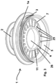
- a sealing element 1 is shown in a second embodiment in a schematic perspective view.
- the reference symbols in 3 correspond to those from 1 .
- ribs 25 are arranged in the sealing element 1 of the second embodiment, which stiffen the radially extending radial section 26 of the sealing body 1a.
- the ribs 25 extend from the pipe sealing lip 11 to the radially opposite inner surface of the stop 7.
- the ribs 25 are arranged in a plurality, the arrangement is preferably such that the distance between two adjacent ribs 25 is the same in each case.
- this measure stabilizes the pipe sealing lip 11 , since forces that act on the pipe sealing lip 11 from a pipe (not shown here) arranged in the opening 4 , are diverted from there to the stop 7 and further to the casing 23 .
- the ribs 25 effectively prevent or significantly reduce an undesired bulging or bulging of the radial section 26 of the sealing element 1 , which can arise as a result of a deflection of the pipe 18 in the sealing element 1 . This avoids possible leaks.
Landscapes
- Engineering & Computer Science (AREA)
- General Engineering & Computer Science (AREA)
- Mechanical Engineering (AREA)
- Gasket Seals (AREA)
Claims (8)
- Elément d'étanchéité (1) pour l'introduction de manière étanche aux fluides dans une gaine (23) d'un tuyau (18), lequel comprend un tuyau pour fluides (19), sur la surface extérieure duquel une couche thermo-isolante (20) est installée, une couche extérieure (21) étant appliquée sur la surface extérieure de la couche thermo-isolante (20) qui sert à protéger le tuyau (18) contre tout endommagement mécanique, dans lequel l'élément d'étanchéité (1) présente un corps d'étanchéité (1a) avec une ouverture (4) et dans lequel élément d'étanchéité (1) sont réalisées une première (2) et une deuxième (3) section d'étanchéité, dans lequel la première section d'étanchéité (2) présente une première face extérieure (13) et la deuxième section d'étanchéité (3) présente une deuxième face extérieure (16), dans lequel la première section d'étanchéité (2) est prévue pour réaliser l'étanchéification par rapport au tuyau (18) et la deuxième section d'étanchéité (3) est prévue pour réaliser l'étanchéification par rapport à la gaine (23), dans lequel est disposé sur la première face extérieure (13) de la première section d'étanchéité (2) un élément de serrage (6), lequel peut être contracté pour pousser une section de la première section d'étanchéité (2) contre la couche extérieure (21) du tuyau (18), et dans lequel est disposé sur la deuxième section d'étanchéité (3) un élément de stabilisation (5), qui est réalisé en tant qu'anneau ou en tant que section annulaire, qui permet de presser la deuxième face extérieure (16) de la deuxième section d'étanchéité (3) sur la surface intérieure de la gaine (23), caractérisé en ce que l'élément de stabilisation (5) est clipsé ou enclenché dans un logement sur le corps d'étanchéité (1a).
- Elément d'étanchéité (1) selon la revendication 1, caractérisé en ce que le matériau de l'élément de stabilisation (5) présente un module d'élasticité plus élevé que le matériau du corps d'étanchéité (1a).
- Elément d'étanchéité (1) selon l'une quelconque des revendications précédentes, caractérisé en ce que le matériau du corps d'étanchéité (1a) est choisi parmi le groupe de matériaux élastomères comprenant le caoutchouc d'éthylène-propylène-diène (EPDM), le caoutchouc à base de copolymère éthylène-propylène (EPM), le caoutchouc à base de polymère et de fluor (FKM, FPM), le caoutchouc perfluoré (FFKM, FFPM), le caoutchouc à base de fluorosilicone (FVMQ), le caoutchouc isoprène (IR), le caoutchouc butyle (IIR), le caoutchouc butadiène (BR), le caoutchouc nitrile (NBR), le caoutchouc chloroprène (CR), la gomme (NR), le caoutchouc silicone, les élastomères thermoplastiques, le polyuréthane (PU), le polyuréthane thermoplastique (TPU), ainsi que les mélanges des éléments susmentionnés.
- Elément d'étanchéité (1) selon l'une quelconque des revendications précédentes, caractérisé en ce que le matériau de l'élément de stabilisation (5) est choisi parmi le groupe comprenant des matières thermoplastiques, de manière préférée des polyoléfines, comme le polyéthylène, le polypropylène et le polybutylène, les polyamides, le polyester, l'ABS (acrylonitrile butadiène styrène), le polystyrène, le polycarbonate, le polychlorure de vinyle, le polyoxyméthylène (POM), et leurs mélanges et copolymères, et/ou parmi le groupe des métaux, comprenant le fer, l'acier, l'aluminium, le laiton, le cuivre, le zinc et leurs mélanges et alliages, et/ou parmi le groupe des matières thermodurcissables, comme une résine époxy.
- Elément d'étanchéité (1) selon l'une quelconque des revendications précédentes, caractérisé en ce que l'élément de serrage (6) est une bande limitée et/ou un ruban limité, qui présente de manière préférée sur une extrémité un dispositif de serrage et/ou de blocage.
- Elément d'étanchéité (1) selon l'une quelconque des revendications précédentes, caractérisé en ce qu'au moins une arête étanche (9) et/ou une lèvre étanche sont réalisées sur au moins une section d'étanchéité (2, 3).
- Elément d'étanchéité (1) selon l'une quelconque des revendications précédentes, caractérisé en ce que celui-ci est réalisé de manière symétrique en rotation par rapport à un axe A.
- Système de tuyaux (30), comprenant au moins un tuyau (18), lequel comprend un tuyau pour fluides (19), sur la surface extérieure duquel une couche thermo-isolante (20) est installée, une couche extérieure (21) étant appliquée sur la surface extérieure de la couche thermo-isolante (2), qui sert à protéger le tuyau (18) contre tout endommagement mécanique, et au moins une gaine (23), dans lequel l'au moins un tuyau (18) est introduit de manière étanche aux fluides dans la gaine (23) avec l'élément d'étanchéité (1) selon l'une quelconque des revendications 1 à 7.
Applications Claiming Priority (1)
| Application Number | Priority Date | Filing Date | Title |
|---|---|---|---|
| DE202016102481.1U DE202016102481U1 (de) | 2016-05-10 | 2016-05-10 | Dichtungselement |
Publications (2)
| Publication Number | Publication Date |
|---|---|
| EP3244119A1 EP3244119A1 (fr) | 2017-11-15 |
| EP3244119B1 true EP3244119B1 (fr) | 2022-02-23 |
Family
ID=58644902
Family Applications (1)
| Application Number | Title | Priority Date | Filing Date |
|---|---|---|---|
| EP17168347.7A Active EP3244119B1 (fr) | 2016-05-10 | 2017-04-27 | Élement d'etancheite |
Country Status (2)
| Country | Link |
|---|---|
| EP (1) | EP3244119B1 (fr) |
| DE (1) | DE202016102481U1 (fr) |
Families Citing this family (5)
| Publication number | Priority date | Publication date | Assignee | Title |
|---|---|---|---|---|
| CN108036446B (zh) * | 2018-01-12 | 2023-07-28 | 浙江星光电科智能家居科技有限公司 | 一种制冷制热系统 |
| DE202021104281U1 (de) * | 2021-08-10 | 2023-03-28 | REHAU Industries SE & Co. KG | Abdeckvorrichtung zum Abdecken einer Verbindungsstelle von medienführenden Rohrendabschnitten |
| DE202021104279U1 (de) * | 2021-08-10 | 2023-03-28 | REHAU Industries SE & Co. KG | Abdeckvorrichtung zum Abdecken einer Verbindungsstelle von medienführenden Rohrendabschnitten |
| CN117382174A (zh) * | 2022-07-05 | 2024-01-12 | 江苏乾度智造高科技有限公司 | 一种应用于打印平台与料池之间的密封结构件 |
| DE102022130920B4 (de) * | 2022-11-22 | 2025-11-13 | Bauconnect Gmbh & Co. Kg | Gießverfahren für einen Adapterring, Adapterring und Rohrkupplungseinheit |
Family Cites Families (4)
| Publication number | Priority date | Publication date | Assignee | Title |
|---|---|---|---|---|
| DE29614105U1 (de) * | 1996-08-14 | 1996-10-02 | G.A. Kettner Gmbh, 65606 Villmar | Abschlußmanschette |
| US6394505B1 (en) * | 2000-07-24 | 2002-05-28 | Geberit Technik | Connection between the intake end of a discharge pipe and the outlet end of a connection curve of a water toilet |
| DE102014106802A1 (de) * | 2014-05-14 | 2015-11-19 | Enerpipe Gmbh | Abdecken eines Rohrabschnittes, insbesondere einer Verbindungsstelle von Fernwärmerohren |
| DE202014104036U1 (de) * | 2014-08-28 | 2014-11-03 | Purus Ab | Rohrverbindung |
-
2016
- 2016-05-10 DE DE202016102481.1U patent/DE202016102481U1/de not_active Expired - Lifetime
-
2017
- 2017-04-27 EP EP17168347.7A patent/EP3244119B1/fr active Active
Also Published As
| Publication number | Publication date |
|---|---|
| DE202016102481U1 (de) | 2017-08-11 |
| EP3244119A1 (fr) | 2017-11-15 |
Similar Documents
| Publication | Publication Date | Title |
|---|---|---|
| EP3244119B1 (fr) | Élement d'etancheite | |
| DE69206880T2 (de) | Dichtung für eine elektrische Leitungsschutzrohrkupplung und Kupplung mit dieser Dichtung | |
| EP2057398A1 (fr) | Dispositif de recouvrement | |
| DE102011102154A1 (de) | Verbinder für eine Fluidleitung und Fluidleitung | |
| DE102011103367A1 (de) | Vorrichtung zum dichtenden Verschließen eines Kabelschutzrohrendes | |
| WO2014180616A1 (fr) | Boîtier pour un module électrique et son procédé de montage | |
| EP4334049A2 (fr) | Système pour raccorder des tuyaux rigides et pour raccorder des tuyaux flexibles et raccords pour un tel système | |
| WO2024008426A1 (fr) | Bague de serrage pour un raccord, et raccord comprenant une bague de serrage | |
| EP3667148B1 (fr) | Compensateur de longueur | |
| WO2013075884A1 (fr) | Vérin, en particulier vérin hydraulique pour les grands fonds | |
| DE102014216045A1 (de) | Konnektor für ein hydraulisches Kupplungssystem | |
| DE102013224027B4 (de) | Durchführungsvorrichtung für Leitungen, insbesondere Hauseinführung | |
| DE102010039225A1 (de) | Tülle | |
| DE102018118763A1 (de) | Dichtungsmodul und Dichtungsanordnung mit einem oder mehreren Dichtungsmodulen | |
| EP2716824A2 (fr) | Tuyau, notamment tuyau de douche | |
| DE102015105651A1 (de) | Dichtungselement für einen Lüftungskanal | |
| EP2213500B1 (fr) | Conduite de carburant et procédé de fabrication d'une conduite de carburant | |
| DE102013009687B4 (de) | Rohrverbindung für thermoplastische Kunststoffrohre | |
| DE102017113489A1 (de) | Warmwasserspeicher | |
| DE202006012463U1 (de) | Abdeckungsvorrichtung | |
| DE102015210005A1 (de) | Konnektor für ein hydraulisches Kupplungssystem | |
| EP4384744B1 (fr) | Dispositif de recouvrement pour recouvrir un point de raccordement de sections d'extrémité de tuyau transportant un fluide | |
| EP4563864A2 (fr) | Raccord destiné à être relié à un tuyau | |
| DE102011015462A1 (de) | Formteil mit mindestens einer Steckmuffe aus Kunststoff sowie mit einer ringförmigen Lippendichtung sowie Verfahren zur Herstellung eines solchen Formteils | |
| DE102019126185A1 (de) | Verbindungselement und Verbindungsanordnung für eine Gasinstallation |
Legal Events
| Date | Code | Title | Description |
|---|---|---|---|
| PUAI | Public reference made under article 153(3) epc to a published international application that has entered the european phase |
Free format text: ORIGINAL CODE: 0009012 |
|
| STAA | Information on the status of an ep patent application or granted ep patent |
Free format text: STATUS: THE APPLICATION HAS BEEN PUBLISHED |
|
| AK | Designated contracting states |
Kind code of ref document: A1 Designated state(s): AL AT BE BG CH CY CZ DE DK EE ES FI FR GB GR HR HU IE IS IT LI LT LU LV MC MK MT NL NO PL PT RO RS SE SI SK SM TR |
|
| AX | Request for extension of the european patent |
Extension state: BA ME |
|
| STAA | Information on the status of an ep patent application or granted ep patent |
Free format text: STATUS: REQUEST FOR EXAMINATION WAS MADE |
|
| 17P | Request for examination filed |
Effective date: 20180514 |
|
| RBV | Designated contracting states (corrected) |
Designated state(s): AL AT BE BG CH CY CZ DE DK EE ES FI FR GB GR HR HU IE IS IT LI LT LU LV MC MK MT NL NO PL PT RO RS SE SI SK SM TR |
|
| STAA | Information on the status of an ep patent application or granted ep patent |
Free format text: STATUS: EXAMINATION IS IN PROGRESS |
|
| 17Q | First examination report despatched |
Effective date: 20200114 |
|
| RAP1 | Party data changed (applicant data changed or rights of an application transferred) |
Owner name: REHAU AG + CO |
|
| GRAP | Despatch of communication of intention to grant a patent |
Free format text: ORIGINAL CODE: EPIDOSNIGR1 |
|
| STAA | Information on the status of an ep patent application or granted ep patent |
Free format text: STATUS: GRANT OF PATENT IS INTENDED |
|
| INTG | Intention to grant announced |
Effective date: 20210908 |
|
| GRAS | Grant fee paid |
Free format text: ORIGINAL CODE: EPIDOSNIGR3 |
|
| GRAA | (expected) grant |
Free format text: ORIGINAL CODE: 0009210 |
|
| STAA | Information on the status of an ep patent application or granted ep patent |
Free format text: STATUS: THE PATENT HAS BEEN GRANTED |
|
| AK | Designated contracting states |
Kind code of ref document: B1 Designated state(s): AL AT BE BG CH CY CZ DE DK EE ES FI FR GB GR HR HU IE IS IT LI LT LU LV MC MK MT NL NO PL PT RO RS SE SI SK SM TR |
|
| REG | Reference to a national code |
Ref country code: GB Ref legal event code: FG4D Free format text: NOT ENGLISH |
|
| REG | Reference to a national code |
Ref country code: CH Ref legal event code: EP |
|
| REG | Reference to a national code |
Ref country code: DE Ref legal event code: R081 Ref document number: 502017012622 Country of ref document: DE Owner name: REHAU INDUSTRIES SE & CO. KG, DE Free format text: FORMER OWNER: REHAU AG + CO, 95111 REHAU, DE |
|
| REG | Reference to a national code |
Ref country code: DE Ref legal event code: R096 Ref document number: 502017012622 Country of ref document: DE |
|
| REG | Reference to a national code |
Ref country code: AT Ref legal event code: REF Ref document number: 1470726 Country of ref document: AT Kind code of ref document: T Effective date: 20220315 |
|
| REG | Reference to a national code |
Ref country code: IE Ref legal event code: FG4D Free format text: LANGUAGE OF EP DOCUMENT: GERMAN |
|
| RAP2 | Party data changed (patent owner data changed or rights of a patent transferred) |
Owner name: REHAU INDUSTRIES SE & CO. KG |
|
| REG | Reference to a national code |
Ref country code: NL Ref legal event code: FP |
|
| REG | Reference to a national code |
Ref country code: LT Ref legal event code: MG9D |
|
| PG25 | Lapsed in a contracting state [announced via postgrant information from national office to epo] |
Ref country code: SE Free format text: LAPSE BECAUSE OF FAILURE TO SUBMIT A TRANSLATION OF THE DESCRIPTION OR TO PAY THE FEE WITHIN THE PRESCRIBED TIME-LIMIT Effective date: 20220223 Ref country code: RS Free format text: LAPSE BECAUSE OF FAILURE TO SUBMIT A TRANSLATION OF THE DESCRIPTION OR TO PAY THE FEE WITHIN THE PRESCRIBED TIME-LIMIT Effective date: 20220223 Ref country code: PT Free format text: LAPSE BECAUSE OF FAILURE TO SUBMIT A TRANSLATION OF THE DESCRIPTION OR TO PAY THE FEE WITHIN THE PRESCRIBED TIME-LIMIT Effective date: 20220623 Ref country code: NO Free format text: LAPSE BECAUSE OF FAILURE TO SUBMIT A TRANSLATION OF THE DESCRIPTION OR TO PAY THE FEE WITHIN THE PRESCRIBED TIME-LIMIT Effective date: 20220523 Ref country code: LT Free format text: LAPSE BECAUSE OF FAILURE TO SUBMIT A TRANSLATION OF THE DESCRIPTION OR TO PAY THE FEE WITHIN THE PRESCRIBED TIME-LIMIT Effective date: 20220223 Ref country code: HR Free format text: LAPSE BECAUSE OF FAILURE TO SUBMIT A TRANSLATION OF THE DESCRIPTION OR TO PAY THE FEE WITHIN THE PRESCRIBED TIME-LIMIT Effective date: 20220223 Ref country code: ES Free format text: LAPSE BECAUSE OF FAILURE TO SUBMIT A TRANSLATION OF THE DESCRIPTION OR TO PAY THE FEE WITHIN THE PRESCRIBED TIME-LIMIT Effective date: 20220223 Ref country code: BG Free format text: LAPSE BECAUSE OF FAILURE TO SUBMIT A TRANSLATION OF THE DESCRIPTION OR TO PAY THE FEE WITHIN THE PRESCRIBED TIME-LIMIT Effective date: 20220523 |
|
| PG25 | Lapsed in a contracting state [announced via postgrant information from national office to epo] |
Ref country code: PL Free format text: LAPSE BECAUSE OF FAILURE TO SUBMIT A TRANSLATION OF THE DESCRIPTION OR TO PAY THE FEE WITHIN THE PRESCRIBED TIME-LIMIT Effective date: 20220223 Ref country code: LV Free format text: LAPSE BECAUSE OF FAILURE TO SUBMIT A TRANSLATION OF THE DESCRIPTION OR TO PAY THE FEE WITHIN THE PRESCRIBED TIME-LIMIT Effective date: 20220223 Ref country code: GR Free format text: LAPSE BECAUSE OF FAILURE TO SUBMIT A TRANSLATION OF THE DESCRIPTION OR TO PAY THE FEE WITHIN THE PRESCRIBED TIME-LIMIT Effective date: 20220524 Ref country code: FI Free format text: LAPSE BECAUSE OF FAILURE TO SUBMIT A TRANSLATION OF THE DESCRIPTION OR TO PAY THE FEE WITHIN THE PRESCRIBED TIME-LIMIT Effective date: 20220223 |
|
| RAP4 | Party data changed (patent owner data changed or rights of a patent transferred) |
Owner name: REHAU INDUSTRIES SE & CO. KG |
|
| PG25 | Lapsed in a contracting state [announced via postgrant information from national office to epo] |
Ref country code: IS Free format text: LAPSE BECAUSE OF FAILURE TO SUBMIT A TRANSLATION OF THE DESCRIPTION OR TO PAY THE FEE WITHIN THE PRESCRIBED TIME-LIMIT Effective date: 20220623 |
|
| PG25 | Lapsed in a contracting state [announced via postgrant information from national office to epo] |
Ref country code: SM Free format text: LAPSE BECAUSE OF FAILURE TO SUBMIT A TRANSLATION OF THE DESCRIPTION OR TO PAY THE FEE WITHIN THE PRESCRIBED TIME-LIMIT Effective date: 20220223 Ref country code: SK Free format text: LAPSE BECAUSE OF FAILURE TO SUBMIT A TRANSLATION OF THE DESCRIPTION OR TO PAY THE FEE WITHIN THE PRESCRIBED TIME-LIMIT Effective date: 20220223 Ref country code: RO Free format text: LAPSE BECAUSE OF FAILURE TO SUBMIT A TRANSLATION OF THE DESCRIPTION OR TO PAY THE FEE WITHIN THE PRESCRIBED TIME-LIMIT Effective date: 20220223 Ref country code: EE Free format text: LAPSE BECAUSE OF FAILURE TO SUBMIT A TRANSLATION OF THE DESCRIPTION OR TO PAY THE FEE WITHIN THE PRESCRIBED TIME-LIMIT Effective date: 20220223 Ref country code: DK Free format text: LAPSE BECAUSE OF FAILURE TO SUBMIT A TRANSLATION OF THE DESCRIPTION OR TO PAY THE FEE WITHIN THE PRESCRIBED TIME-LIMIT Effective date: 20220223 Ref country code: CZ Free format text: LAPSE BECAUSE OF FAILURE TO SUBMIT A TRANSLATION OF THE DESCRIPTION OR TO PAY THE FEE WITHIN THE PRESCRIBED TIME-LIMIT Effective date: 20220223 |
|
| REG | Reference to a national code |
Ref country code: DE Ref legal event code: R097 Ref document number: 502017012622 Country of ref document: DE |
|
| PG25 | Lapsed in a contracting state [announced via postgrant information from national office to epo] |
Ref country code: AL Free format text: LAPSE BECAUSE OF FAILURE TO SUBMIT A TRANSLATION OF THE DESCRIPTION OR TO PAY THE FEE WITHIN THE PRESCRIBED TIME-LIMIT Effective date: 20220223 |
|
| PLBE | No opposition filed within time limit |
Free format text: ORIGINAL CODE: 0009261 |
|
| STAA | Information on the status of an ep patent application or granted ep patent |
Free format text: STATUS: NO OPPOSITION FILED WITHIN TIME LIMIT |
|
| PG25 | Lapsed in a contracting state [announced via postgrant information from national office to epo] |
Ref country code: MC Free format text: LAPSE BECAUSE OF FAILURE TO SUBMIT A TRANSLATION OF THE DESCRIPTION OR TO PAY THE FEE WITHIN THE PRESCRIBED TIME-LIMIT Effective date: 20220223 Ref country code: LU Free format text: LAPSE BECAUSE OF NON-PAYMENT OF DUE FEES Effective date: 20220427 |
|
| 26N | No opposition filed |
Effective date: 20221124 |
|
| PG25 | Lapsed in a contracting state [announced via postgrant information from national office to epo] |
Ref country code: SI Free format text: LAPSE BECAUSE OF FAILURE TO SUBMIT A TRANSLATION OF THE DESCRIPTION OR TO PAY THE FEE WITHIN THE PRESCRIBED TIME-LIMIT Effective date: 20220223 |
|
| PG25 | Lapsed in a contracting state [announced via postgrant information from national office to epo] |
Ref country code: IE Free format text: LAPSE BECAUSE OF NON-PAYMENT OF DUE FEES Effective date: 20220427 |
|
| PG25 | Lapsed in a contracting state [announced via postgrant information from national office to epo] |
Ref country code: HU Free format text: LAPSE BECAUSE OF FAILURE TO SUBMIT A TRANSLATION OF THE DESCRIPTION OR TO PAY THE FEE WITHIN THE PRESCRIBED TIME-LIMIT; INVALID AB INITIO Effective date: 20170427 |
|
| PG25 | Lapsed in a contracting state [announced via postgrant information from national office to epo] |
Ref country code: MK Free format text: LAPSE BECAUSE OF FAILURE TO SUBMIT A TRANSLATION OF THE DESCRIPTION OR TO PAY THE FEE WITHIN THE PRESCRIBED TIME-LIMIT Effective date: 20220223 Ref country code: CY Free format text: LAPSE BECAUSE OF FAILURE TO SUBMIT A TRANSLATION OF THE DESCRIPTION OR TO PAY THE FEE WITHIN THE PRESCRIBED TIME-LIMIT Effective date: 20220223 |
|
| PG25 | Lapsed in a contracting state [announced via postgrant information from national office to epo] |
Ref country code: MT Free format text: LAPSE BECAUSE OF FAILURE TO SUBMIT A TRANSLATION OF THE DESCRIPTION OR TO PAY THE FEE WITHIN THE PRESCRIBED TIME-LIMIT Effective date: 20220223 |
|
| PGFP | Annual fee paid to national office [announced via postgrant information from national office to epo] |
Ref country code: NL Payment date: 20250311 Year of fee payment: 9 |
|
| PGFP | Annual fee paid to national office [announced via postgrant information from national office to epo] |
Ref country code: BE Payment date: 20250311 Year of fee payment: 9 |
|
| PGFP | Annual fee paid to national office [announced via postgrant information from national office to epo] |
Ref country code: DE Payment date: 20250430 Year of fee payment: 9 |
|
| PGFP | Annual fee paid to national office [announced via postgrant information from national office to epo] |
Ref country code: IT Payment date: 20250429 Year of fee payment: 9 |
|
| PGFP | Annual fee paid to national office [announced via postgrant information from national office to epo] |
Ref country code: FR Payment date: 20250407 Year of fee payment: 9 |
|
| PGFP | Annual fee paid to national office [announced via postgrant information from national office to epo] |
Ref country code: CH Payment date: 20250501 Year of fee payment: 9 |
|
| PGFP | Annual fee paid to national office [announced via postgrant information from national office to epo] |
Ref country code: AT Payment date: 20250311 Year of fee payment: 9 |
|
| PG25 | Lapsed in a contracting state [announced via postgrant information from national office to epo] |
Ref country code: TR Free format text: LAPSE BECAUSE OF FAILURE TO SUBMIT A TRANSLATION OF THE DESCRIPTION OR TO PAY THE FEE WITHIN THE PRESCRIBED TIME-LIMIT Effective date: 20220223 |
|
| PGFP | Annual fee paid to national office [announced via postgrant information from national office to epo] |
Ref country code: GB Payment date: 20260326 Year of fee payment: 10 |