EP3667152A1 - Récipient haute pression et procédé pour sa fabrication - Google Patents
Récipient haute pression et procédé pour sa fabrication Download PDFInfo
- Publication number
- EP3667152A1 EP3667152A1 EP18858670.5A EP18858670A EP3667152A1 EP 3667152 A1 EP3667152 A1 EP 3667152A1 EP 18858670 A EP18858670 A EP 18858670A EP 3667152 A1 EP3667152 A1 EP 3667152A1
- Authority
- EP
- European Patent Office
- Prior art keywords
- layer
- composite material
- protective layer
- heat
- dome
- Prior art date
- Legal status (The legal status is an assumption and is not a legal conclusion. Google has not performed a legal analysis and makes no representation as to the accuracy of the status listed.)
- Granted
Links
Images


Classifications
-
- F—MECHANICAL ENGINEERING; LIGHTING; HEATING; WEAPONS; BLASTING
- F17—STORING OR DISTRIBUTING GASES OR LIQUIDS
- F17C—VESSELS FOR CONTAINING OR STORING COMPRESSED, LIQUEFIED OR SOLIDIFIED GASES; FIXED-CAPACITY GAS-HOLDERS; FILLING VESSELS WITH, OR DISCHARGING FROM VESSELS, COMPRESSED, LIQUEFIED, OR SOLIDIFIED GASES
- F17C1/00—Pressure vessels, e.g. gas cylinder, gas tank, replaceable cartridge
- F17C1/16—Pressure vessels, e.g. gas cylinder, gas tank, replaceable cartridge constructed of plastics materials
-
- B—PERFORMING OPERATIONS; TRANSPORTING
- B29—WORKING OF PLASTICS; WORKING OF SUBSTANCES IN A PLASTIC STATE IN GENERAL
- B29C—SHAPING OR JOINING OF PLASTICS; SHAPING OF MATERIAL IN A PLASTIC STATE, NOT OTHERWISE PROVIDED FOR; AFTER-TREATMENT OF THE SHAPED PRODUCTS, e.g. REPAIRING
- B29C45/00—Injection moulding, i.e. forcing the required volume of moulding material through a nozzle into a closed mould; Apparatus therefor
- B29C45/14—Injection moulding, i.e. forcing the required volume of moulding material through a nozzle into a closed mould; Apparatus therefor incorporating preformed parts or layers, e.g. injection moulding around inserts or for coating articles
- B29C45/14598—Coating tubular articles
- B29C45/14622—Lining the inner or outer surface of tubular articles
-
- B—PERFORMING OPERATIONS; TRANSPORTING
- B29—WORKING OF PLASTICS; WORKING OF SUBSTANCES IN A PLASTIC STATE IN GENERAL
- B29C—SHAPING OR JOINING OF PLASTICS; SHAPING OF MATERIAL IN A PLASTIC STATE, NOT OTHERWISE PROVIDED FOR; AFTER-TREATMENT OF THE SHAPED PRODUCTS, e.g. REPAIRING
- B29C45/00—Injection moulding, i.e. forcing the required volume of moulding material through a nozzle into a closed mould; Apparatus therefor
- B29C45/14—Injection moulding, i.e. forcing the required volume of moulding material through a nozzle into a closed mould; Apparatus therefor incorporating preformed parts or layers, e.g. injection moulding around inserts or for coating articles
- B29C45/14778—Injection moulding, i.e. forcing the required volume of moulding material through a nozzle into a closed mould; Apparatus therefor incorporating preformed parts or layers, e.g. injection moulding around inserts or for coating articles the article consisting of a material with particular properties, e.g. porous, brittle
- B29C45/14811—Multilayered articles
-
- B—PERFORMING OPERATIONS; TRANSPORTING
- B29—WORKING OF PLASTICS; WORKING OF SUBSTANCES IN A PLASTIC STATE IN GENERAL
- B29C—SHAPING OR JOINING OF PLASTICS; SHAPING OF MATERIAL IN A PLASTIC STATE, NOT OTHERWISE PROVIDED FOR; AFTER-TREATMENT OF THE SHAPED PRODUCTS, e.g. REPAIRING
- B29C45/00—Injection moulding, i.e. forcing the required volume of moulding material through a nozzle into a closed mould; Apparatus therefor
- B29C45/16—Making multilayered or multicoloured articles
- B29C45/1642—Making multilayered or multicoloured articles having a "sandwich" structure
-
- B—PERFORMING OPERATIONS; TRANSPORTING
- B29—WORKING OF PLASTICS; WORKING OF SUBSTANCES IN A PLASTIC STATE IN GENERAL
- B29C—SHAPING OR JOINING OF PLASTICS; SHAPING OF MATERIAL IN A PLASTIC STATE, NOT OTHERWISE PROVIDED FOR; AFTER-TREATMENT OF THE SHAPED PRODUCTS, e.g. REPAIRING
- B29C45/00—Injection moulding, i.e. forcing the required volume of moulding material through a nozzle into a closed mould; Apparatus therefor
- B29C45/16—Making multilayered or multicoloured articles
- B29C45/1657—Making multilayered or multicoloured articles using means for adhering or bonding the layers or parts to each other
-
- F—MECHANICAL ENGINEERING; LIGHTING; HEATING; WEAPONS; BLASTING
- F17—STORING OR DISTRIBUTING GASES OR LIQUIDS
- F17C—VESSELS FOR CONTAINING OR STORING COMPRESSED, LIQUEFIED OR SOLIDIFIED GASES; FIXED-CAPACITY GAS-HOLDERS; FILLING VESSELS WITH, OR DISCHARGING FROM VESSELS, COMPRESSED, LIQUEFIED, OR SOLIDIFIED GASES
- F17C1/00—Pressure vessels, e.g. gas cylinder, gas tank, replaceable cartridge
- F17C1/02—Pressure vessels, e.g. gas cylinder, gas tank, replaceable cartridge involving reinforcing arrangements
- F17C1/04—Protecting sheathings
- F17C1/06—Protecting sheathings built-up from wound-on bands or filamentary material, e.g. wires
-
- F—MECHANICAL ENGINEERING; LIGHTING; HEATING; WEAPONS; BLASTING
- F17—STORING OR DISTRIBUTING GASES OR LIQUIDS
- F17C—VESSELS FOR CONTAINING OR STORING COMPRESSED, LIQUEFIED OR SOLIDIFIED GASES; FIXED-CAPACITY GAS-HOLDERS; FILLING VESSELS WITH, OR DISCHARGING FROM VESSELS, COMPRESSED, LIQUEFIED, OR SOLIDIFIED GASES
- F17C13/00—Details of vessels or of the filling or discharging of vessels
- F17C13/002—Details of vessels or of the filling or discharging of vessels for vessels under pressure
-
- F—MECHANICAL ENGINEERING; LIGHTING; HEATING; WEAPONS; BLASTING
- F17—STORING OR DISTRIBUTING GASES OR LIQUIDS
- F17C—VESSELS FOR CONTAINING OR STORING COMPRESSED, LIQUEFIED OR SOLIDIFIED GASES; FIXED-CAPACITY GAS-HOLDERS; FILLING VESSELS WITH, OR DISCHARGING FROM VESSELS, COMPRESSED, LIQUEFIED, OR SOLIDIFIED GASES
- F17C2201/00—Vessel construction, in particular geometry, arrangement or size
- F17C2201/01—Shape
- F17C2201/0104—Shape cylindrical
- F17C2201/0109—Shape cylindrical with exteriorly curved end-piece
-
- F—MECHANICAL ENGINEERING; LIGHTING; HEATING; WEAPONS; BLASTING
- F17—STORING OR DISTRIBUTING GASES OR LIQUIDS
- F17C—VESSELS FOR CONTAINING OR STORING COMPRESSED, LIQUEFIED OR SOLIDIFIED GASES; FIXED-CAPACITY GAS-HOLDERS; FILLING VESSELS WITH, OR DISCHARGING FROM VESSELS, COMPRESSED, LIQUEFIED, OR SOLIDIFIED GASES
- F17C2201/00—Vessel construction, in particular geometry, arrangement or size
- F17C2201/05—Size
- F17C2201/056—Small (<1 m3)
-
- F—MECHANICAL ENGINEERING; LIGHTING; HEATING; WEAPONS; BLASTING
- F17—STORING OR DISTRIBUTING GASES OR LIQUIDS
- F17C—VESSELS FOR CONTAINING OR STORING COMPRESSED, LIQUEFIED OR SOLIDIFIED GASES; FIXED-CAPACITY GAS-HOLDERS; FILLING VESSELS WITH, OR DISCHARGING FROM VESSELS, COMPRESSED, LIQUEFIED, OR SOLIDIFIED GASES
- F17C2203/00—Vessel construction, in particular walls or details thereof
- F17C2203/06—Materials for walls or layers thereof; Properties or structures of walls or their materials
- F17C2203/0602—Wall structures; Special features thereof
- F17C2203/0604—Liners
-
- F—MECHANICAL ENGINEERING; LIGHTING; HEATING; WEAPONS; BLASTING
- F17—STORING OR DISTRIBUTING GASES OR LIQUIDS
- F17C—VESSELS FOR CONTAINING OR STORING COMPRESSED, LIQUEFIED OR SOLIDIFIED GASES; FIXED-CAPACITY GAS-HOLDERS; FILLING VESSELS WITH, OR DISCHARGING FROM VESSELS, COMPRESSED, LIQUEFIED, OR SOLIDIFIED GASES
- F17C2203/00—Vessel construction, in particular walls or details thereof
- F17C2203/06—Materials for walls or layers thereof; Properties or structures of walls or their materials
- F17C2203/0602—Wall structures; Special features thereof
- F17C2203/0607—Coatings
-
- F—MECHANICAL ENGINEERING; LIGHTING; HEATING; WEAPONS; BLASTING
- F17—STORING OR DISTRIBUTING GASES OR LIQUIDS
- F17C—VESSELS FOR CONTAINING OR STORING COMPRESSED, LIQUEFIED OR SOLIDIFIED GASES; FIXED-CAPACITY GAS-HOLDERS; FILLING VESSELS WITH, OR DISCHARGING FROM VESSELS, COMPRESSED, LIQUEFIED, OR SOLIDIFIED GASES
- F17C2203/00—Vessel construction, in particular walls or details thereof
- F17C2203/06—Materials for walls or layers thereof; Properties or structures of walls or their materials
- F17C2203/0602—Wall structures; Special features thereof
- F17C2203/0612—Wall structures
- F17C2203/0614—Single wall
- F17C2203/0621—Single wall with three layers
-
- F—MECHANICAL ENGINEERING; LIGHTING; HEATING; WEAPONS; BLASTING
- F17—STORING OR DISTRIBUTING GASES OR LIQUIDS
- F17C—VESSELS FOR CONTAINING OR STORING COMPRESSED, LIQUEFIED OR SOLIDIFIED GASES; FIXED-CAPACITY GAS-HOLDERS; FILLING VESSELS WITH, OR DISCHARGING FROM VESSELS, COMPRESSED, LIQUEFIED, OR SOLIDIFIED GASES
- F17C2203/00—Vessel construction, in particular walls or details thereof
- F17C2203/06—Materials for walls or layers thereof; Properties or structures of walls or their materials
- F17C2203/0634—Materials for walls or layers thereof
- F17C2203/0658—Synthetics
- F17C2203/066—Plastics
-
- F—MECHANICAL ENGINEERING; LIGHTING; HEATING; WEAPONS; BLASTING
- F17—STORING OR DISTRIBUTING GASES OR LIQUIDS
- F17C—VESSELS FOR CONTAINING OR STORING COMPRESSED, LIQUEFIED OR SOLIDIFIED GASES; FIXED-CAPACITY GAS-HOLDERS; FILLING VESSELS WITH, OR DISCHARGING FROM VESSELS, COMPRESSED, LIQUEFIED, OR SOLIDIFIED GASES
- F17C2203/00—Vessel construction, in particular walls or details thereof
- F17C2203/06—Materials for walls or layers thereof; Properties or structures of walls or their materials
- F17C2203/0634—Materials for walls or layers thereof
- F17C2203/0658—Synthetics
- F17C2203/0663—Synthetics in form of fibers or filaments
- F17C2203/0673—Polymers
-
- F—MECHANICAL ENGINEERING; LIGHTING; HEATING; WEAPONS; BLASTING
- F17—STORING OR DISTRIBUTING GASES OR LIQUIDS
- F17C—VESSELS FOR CONTAINING OR STORING COMPRESSED, LIQUEFIED OR SOLIDIFIED GASES; FIXED-CAPACITY GAS-HOLDERS; FILLING VESSELS WITH, OR DISCHARGING FROM VESSELS, COMPRESSED, LIQUEFIED, OR SOLIDIFIED GASES
- F17C2203/00—Vessel construction, in particular walls or details thereof
- F17C2203/06—Materials for walls or layers thereof; Properties or structures of walls or their materials
- F17C2203/0634—Materials for walls or layers thereof
- F17C2203/0658—Synthetics
- F17C2203/0675—Synthetics with details of composition
-
- F—MECHANICAL ENGINEERING; LIGHTING; HEATING; WEAPONS; BLASTING
- F17—STORING OR DISTRIBUTING GASES OR LIQUIDS
- F17C—VESSELS FOR CONTAINING OR STORING COMPRESSED, LIQUEFIED OR SOLIDIFIED GASES; FIXED-CAPACITY GAS-HOLDERS; FILLING VESSELS WITH, OR DISCHARGING FROM VESSELS, COMPRESSED, LIQUEFIED, OR SOLIDIFIED GASES
- F17C2209/00—Vessel construction, in particular methods of manufacturing
- F17C2209/21—Shaping processes
- F17C2209/2109—Moulding
- F17C2209/2118—Moulding by injection
-
- F—MECHANICAL ENGINEERING; LIGHTING; HEATING; WEAPONS; BLASTING
- F17—STORING OR DISTRIBUTING GASES OR LIQUIDS
- F17C—VESSELS FOR CONTAINING OR STORING COMPRESSED, LIQUEFIED OR SOLIDIFIED GASES; FIXED-CAPACITY GAS-HOLDERS; FILLING VESSELS WITH, OR DISCHARGING FROM VESSELS, COMPRESSED, LIQUEFIED, OR SOLIDIFIED GASES
- F17C2209/00—Vessel construction, in particular methods of manufacturing
- F17C2209/23—Manufacturing of particular parts or at special locations
- F17C2209/232—Manufacturing of particular parts or at special locations of walls
-
- F—MECHANICAL ENGINEERING; LIGHTING; HEATING; WEAPONS; BLASTING
- F17—STORING OR DISTRIBUTING GASES OR LIQUIDS
- F17C—VESSELS FOR CONTAINING OR STORING COMPRESSED, LIQUEFIED OR SOLIDIFIED GASES; FIXED-CAPACITY GAS-HOLDERS; FILLING VESSELS WITH, OR DISCHARGING FROM VESSELS, COMPRESSED, LIQUEFIED, OR SOLIDIFIED GASES
- F17C2209/00—Vessel construction, in particular methods of manufacturing
- F17C2209/23—Manufacturing of particular parts or at special locations
- F17C2209/234—Manufacturing of particular parts or at special locations of closing end pieces, e.g. caps
-
- F—MECHANICAL ENGINEERING; LIGHTING; HEATING; WEAPONS; BLASTING
- F17—STORING OR DISTRIBUTING GASES OR LIQUIDS
- F17C—VESSELS FOR CONTAINING OR STORING COMPRESSED, LIQUEFIED OR SOLIDIFIED GASES; FIXED-CAPACITY GAS-HOLDERS; FILLING VESSELS WITH, OR DISCHARGING FROM VESSELS, COMPRESSED, LIQUEFIED, OR SOLIDIFIED GASES
- F17C2221/00—Handled fluid, in particular type of fluid
- F17C2221/01—Pure fluids
- F17C2221/012—Hydrogen
-
- F—MECHANICAL ENGINEERING; LIGHTING; HEATING; WEAPONS; BLASTING
- F17—STORING OR DISTRIBUTING GASES OR LIQUIDS
- F17C—VESSELS FOR CONTAINING OR STORING COMPRESSED, LIQUEFIED OR SOLIDIFIED GASES; FIXED-CAPACITY GAS-HOLDERS; FILLING VESSELS WITH, OR DISCHARGING FROM VESSELS, COMPRESSED, LIQUEFIED, OR SOLIDIFIED GASES
- F17C2221/00—Handled fluid, in particular type of fluid
- F17C2221/03—Mixtures
- F17C2221/032—Hydrocarbons
- F17C2221/033—Methane, e.g. natural gas, CNG, LNG, GNL, GNC, PLNG
-
- F—MECHANICAL ENGINEERING; LIGHTING; HEATING; WEAPONS; BLASTING
- F17—STORING OR DISTRIBUTING GASES OR LIQUIDS
- F17C—VESSELS FOR CONTAINING OR STORING COMPRESSED, LIQUEFIED OR SOLIDIFIED GASES; FIXED-CAPACITY GAS-HOLDERS; FILLING VESSELS WITH, OR DISCHARGING FROM VESSELS, COMPRESSED, LIQUEFIED, OR SOLIDIFIED GASES
- F17C2223/00—Handled fluid before transfer, i.e. state of fluid when stored in the vessel or before transfer from the vessel
- F17C2223/01—Handled fluid before transfer, i.e. state of fluid when stored in the vessel or before transfer from the vessel characterised by the phase
- F17C2223/0107—Single phase
- F17C2223/0123—Single phase gaseous, e.g. CNG, GNC
-
- F—MECHANICAL ENGINEERING; LIGHTING; HEATING; WEAPONS; BLASTING
- F17—STORING OR DISTRIBUTING GASES OR LIQUIDS
- F17C—VESSELS FOR CONTAINING OR STORING COMPRESSED, LIQUEFIED OR SOLIDIFIED GASES; FIXED-CAPACITY GAS-HOLDERS; FILLING VESSELS WITH, OR DISCHARGING FROM VESSELS, COMPRESSED, LIQUEFIED, OR SOLIDIFIED GASES
- F17C2223/00—Handled fluid before transfer, i.e. state of fluid when stored in the vessel or before transfer from the vessel
- F17C2223/03—Handled fluid before transfer, i.e. state of fluid when stored in the vessel or before transfer from the vessel characterised by the pressure level
- F17C2223/036—Very high pressure (>80 bar)
-
- F—MECHANICAL ENGINEERING; LIGHTING; HEATING; WEAPONS; BLASTING
- F17—STORING OR DISTRIBUTING GASES OR LIQUIDS
- F17C—VESSELS FOR CONTAINING OR STORING COMPRESSED, LIQUEFIED OR SOLIDIFIED GASES; FIXED-CAPACITY GAS-HOLDERS; FILLING VESSELS WITH, OR DISCHARGING FROM VESSELS, COMPRESSED, LIQUEFIED, OR SOLIDIFIED GASES
- F17C2260/00—Purposes of gas storage and gas handling
- F17C2260/01—Improving mechanical properties or manufacturing
- F17C2260/011—Improving strength
-
- F—MECHANICAL ENGINEERING; LIGHTING; HEATING; WEAPONS; BLASTING
- F17—STORING OR DISTRIBUTING GASES OR LIQUIDS
- F17C—VESSELS FOR CONTAINING OR STORING COMPRESSED, LIQUEFIED OR SOLIDIFIED GASES; FIXED-CAPACITY GAS-HOLDERS; FILLING VESSELS WITH, OR DISCHARGING FROM VESSELS, COMPRESSED, LIQUEFIED, OR SOLIDIFIED GASES
- F17C2270/00—Applications
- F17C2270/01—Applications for fluid transport or storage
- F17C2270/0165—Applications for fluid transport or storage on the road
- F17C2270/0168—Applications for fluid transport or storage on the road by vehicles
- F17C2270/0178—Cars
-
- F—MECHANICAL ENGINEERING; LIGHTING; HEATING; WEAPONS; BLASTING
- F17—STORING OR DISTRIBUTING GASES OR LIQUIDS
- F17C—VESSELS FOR CONTAINING OR STORING COMPRESSED, LIQUEFIED OR SOLIDIFIED GASES; FIXED-CAPACITY GAS-HOLDERS; FILLING VESSELS WITH, OR DISCHARGING FROM VESSELS, COMPRESSED, LIQUEFIED, OR SOLIDIFIED GASES
- F17C2270/00—Applications
- F17C2270/01—Applications for fluid transport or storage
- F17C2270/0165—Applications for fluid transport or storage on the road
- F17C2270/0184—Fuel cells
-
- Y—GENERAL TAGGING OF NEW TECHNOLOGICAL DEVELOPMENTS; GENERAL TAGGING OF CROSS-SECTIONAL TECHNOLOGIES SPANNING OVER SEVERAL SECTIONS OF THE IPC; TECHNICAL SUBJECTS COVERED BY FORMER USPC CROSS-REFERENCE ART COLLECTIONS [XRACs] AND DIGESTS
- Y02—TECHNOLOGIES OR APPLICATIONS FOR MITIGATION OR ADAPTATION AGAINST CLIMATE CHANGE
- Y02E—REDUCTION OF GREENHOUSE GAS [GHG] EMISSIONS, RELATED TO ENERGY GENERATION, TRANSMISSION OR DISTRIBUTION
- Y02E60/00—Enabling technologies; Technologies with a potential or indirect contribution to GHG emissions mitigation
- Y02E60/30—Hydrogen technology
- Y02E60/32—Hydrogen storage
Definitions
- the present invention relates to a high-pressure vessel and a manufacturing method thereof. More particularly, the present invention relates to a high-pressure vessel capable of safely storing high-pressure gas, such as a fuel tank of a natural gas vehicle or a hydrogen tank of a fuel cell vehicle, and a manufacturing method thereof.
- high-pressure gas such as a fuel tank of a natural gas vehicle or a hydrogen tank of a fuel cell vehicle
- a natural gas (CNG) vehicle or a hydrogen fuel cell vehicle is equipped with a high-pressure vessel to compress gaseous fuel at high pressure and thereby store the gaseous fuel.
- the high-pressure vessel is manufactured through the following manufacturing process: a liner is made of synthetic resin to reduce weight, a composite material such as carbon fiber is wound thereon, a protective pad is attached thereon again to absorb shocks on an outer surface and thereby prevent damage to liner, and glass fiber is wound again thereon to prevent the removal of the protective pad and prevent chipping.
- a liner is made of synthetic resin to reduce weight
- a composite material such as carbon fiber
- a protective pad is attached thereon again to absorb shocks on an outer surface and thereby prevent damage to liner
- glass fiber is wound again thereon to prevent the removal of the protective pad and prevent chipping.
- polymer resin epoxy
- FIG. 1 illustrates the structure of a conventional high-pressure vessel.
- the high-pressure vessel includes a liner 10 including a cylinder and dome-shaped spaces provided on both ends of the cylinder and storing a high-pressure fluid therein, and a composite material 20 provided an outer surface of the liner.
- the vessel further includes on an outer surface of the composite material 20 a protective-pad layer 30 to protect the high-pressure vessel, a glass fiber layer 40, and a fire-resisting material layer 50.
- the protective-pad layer 30 serves to protect the liner from shocks of the outer surface
- the glass fiber layer 40 serves to secure the protective pad and prevent chipping.
- the fire-resisting material layer 50 of the outer surface serves to provide fire resistance in the event of fire.
- the composite material 20 on the outer surface of the liner 10 is not uniform in surface shape, there is a problem that an edge portion thereof is thinnest when winding. Thus, when the protective-pad layer 30 is attached to the surface, the surface of the composite material 20 is not uniform, so that adhesive strength is not sufficiently ensured.
- the glass fiber layer 40 is manufactured through a manufacturing process for winding glass fiber (e.g. filament), and time and cost required for winding are large, so that production efficiency may be undesirably deteriorated.
- a manufacturing process for winding glass fiber e.g. filament
- the fire-resisting material layer 50 is made by applying spray containing fire-resisting ingredients.
- spray containing fire-resisting ingredients it is very complicated to apply the spray in a uniform application amount.
- the applied fire-resisting material may be lost, so that the fire resistance may be lost.
- time and cost required for the process of manufacturing the high-pressure vessel are undesirably large according to respective sequential processes, and it is difficult to obtain a uniform quality despite the large manufacturing process and time.
- KR 10-1161229 B has been proposed.
- the present invention has been made to solve the above-mentioned problems and difficulties and relates to a high-pressure vessel having shock resistance, heat resistance, and chipping resistance, and a method of manufacturing a high-pressure vessel that simplifies a manufacturing process and increases production efficiency.
- the present invention provides a high-pressure vessel, including: a liner including a cylinder portion and dome portions disposed at both ends of the cylinder portion, and storing a high-pressure fluid therein, each of the dome portions having a dome shape; a composite material layer surrounding an outer surface of the liner; and a protective layer surrounding an outer surface of the composite material layer and including a shock-absorbing layer, a heat-resistant layer, and a surface protective layer, which are sequentially laminated, wherein the shock-absorbing layer of the protective layer may be made of a resin material, and may be formed by an injection molding method or a foaming method on an inner surface of the heat-resistant layer.
- the surface protective layer of the protective layer may be made of a resin material, and may be formed on an outer surface of the heat-resistant layer through injection molding or thermoforming.
- the protective layer may include a cylinder protecting portion to protect the cylinder portion and a dome protecting portion to protect the dome portion, thus surrounding an outer surface of the composite material layer.
- the shock-absorbing layer may contain a urethane material.
- the heat-resistant layer may contain a ceramic material.
- the surface protective layer may contain a Polyethylene Terephthalate (PET) material or a Low Weight Reinforced Thermoplastic (LWRT) material.
- PET Polyethylene Terephthalate
- LWRT Low Weight Reinforced Thermoplastic
- the LWRT material of the surface protective layer may be reinforced with Glass Fiber (GF).
- GF Glass Fiber
- the present invention provides a method of manufacturing a high-pressure vessel according to the invention, the method including: coupling a composite material layer with a protective layer by attaching the protective layer to an outer surface of the composite material layer or by forming a shock-absorbing layer between the outer surface of the composite material layer and an inner surface of the heat-resistant layer through injection molding or foaming.
- the method may further include forming the surface protective layer on an outer surface of the heat-resistant layer through injection molding or thermoforming, before the coupling the composite material layer with the protective layer.
- the surface protective layer may be formed through injection molding or thermoforming to cover a side surface of the heat-resistant layer, at the forming the surface protective layer on the outer surface of the heat-resistant layer through injection molding or thermoforming.
- the protective layer may include a cylinder protecting portion to protect a cylinder portion and a dome protecting portion to protect a dome portion, and at the coupling the composite material layer with the protective layer, the cylinder protecting portion may attach the protective layer to the outer surface of the composite material layer, and the dome protecting portion may couple the composite material layer with the protective layer by forming the shock-absorbing layer between the outer surface of the composite material layer and the heat-resistant layer through injection molding or foaming.
- the shock-absorbing layer may be formed through injection molding or foaming to fill a gap between the cylinder protecting portion and the dome protecting portion.
- the protective layer composed of the shock-absorbing layer and the heat-resistant layer may include a cylinder protecting portion to protect a cylinder portion and a dome protecting portion to protect a dome portion, and at the coupling the composite material layer with the protective layer, the cylinder protecting portion and the dome protecting portion may couple the composite material layer with the protective layer by integrally forming the shock-absorbing layer between the outer surface of the composite material layer and the heat-resistant layer through injection molding or foaming.
- a high-pressure vessel and a manufacturing method thereof according to the present invention are advantageous in that a protective layer is completed in a single process, so that the manufacturing process is simplified, and thereby manufacturing cost and time are reduced and production efficiency is increased.
- shock resistance, the heat resistance, and the chipping resistance of a high-pressure vessel are guaranteed, so that the safety of the high-pressure vessel is ensured, and quality deviation is reduced.
- the invention has effects of solving a problem wherein a fire-resisting material is lost by shocks acting on an outer surface, so that fire resistance is lost.
- first, second, etc. may be used herein to describe various elements, these elements should not be limited by these terms. These terms are only used to distinguish one element from another element. For instance, a first element discussed below could be termed a second element without departing from the teachings of the present disclosure. Similarly, the second element could also be termed the first element.
- FIG. 2 illustrates a high-pressure vessel and a protective layer according to an embodiment of the present invention.
- the high-pressure vessel A includes a liner X including a cylinder portion and dome portions disposed at both ends of the cylinder portion, and storing a high-pressure fluid therein, each of the dome portions having a dome shape, a composite material layer Y surrounding an outer surface of the liner X, and a protective layer Z surrounding an outer surface of the composite material layer Y and including a shock-absorbing layer L1, a heat-resistant layer L2, and a surface protective layer L3, which are sequentially laminated.
- the shock-absorbing layer L1 of the protective layer Z is made of a resin material, and is formed by an injection molding method or a foaming method on an inner surface of the heat-resistant layer L2.
- the liner X storing the high-pressure fluid therein may be formed of a plastic material such as Polyamide 6 (PA6) or Polyethylene (PE). As shown in the drawings, the liner may be shaped to have the cylinder portion and the dome portions disposed at both ends of the cylinder portion, each dome portion having the dome shape. The liner X may have a space to store the high-pressure fluid such as the high-pressure gas therein.
- PA6 Polyamide 6
- PE Polyethylene
- the composite material layer Y may be formed to surround the outer surface of the liner X.
- the composite material layer Y may be formed of a material obtained by mixing Carbon Fiber (CF) or Glass Fiber (GF) with resin.
- the composite material layer Y may be made by winding composite fiber.
- an edge portion between the cylinder portion and the dome portion may be thinnest. Therefore, in order to prevent the edge portion from being vulnerable to shocks or heat, the protective layer Z may be formed thicker at the edge portion.
- the shock-absorbing layer L1 may be formed thicker at the edge portion.
- a flat portion such as the cylinder portion forms a uniform layer while the composite material layer Y and the protective layer Z each having a thickness.
- the composite material layer Y is thinner than the cylinder portion.
- the protective layer Z is formed thicker than the cylinder portion, thus compensating for the composite material layer Y that is reduced in thickness.
- the protective layer Z may surround the outer surface of the composite material layer Y, and may sequentially laminate the shock-absorbing layer L1, the heat-resistant layer L2, and the surface protective layer L3 on the outer surface of the composite material layer Y.
- the shock-absorbing layer L1 may be made of the resin material, and may be formed by the injection molding method or the foaming method on the inner surface of the heat-resistant layer L2. To be more specific, the shock-absorbing layer L1 may be formed on the inner surface of the heat-resistant layer L2 through injection molding and then attached to the outer surface of the composite material layer Y, or may be directly formed through injection molding between the heat-resistant layer L2 and the outer surface of the composite material layer Y.
- the shock-absorbing layer L1 may contain a urethane material.
- the shock-absorbing layer L1 may be made by inserting the heat-resistant layer L2 of the ceramic material into a mold and then performing injecting molding or foaming on the inner surface of the heat-resistant layer L2, or by inserting the high-pressure vessel to which the liner 10 and the composite material layer Y are applied, and the heat-resistant layer L2 into a mold and then performing injecting molding or foaming therebetween.
- the heat-resistant layer L2 may contain a ceramic material.
- the surface protective layer L3 may contain a Polyethylene Terephthalate (PET) material or a Low Weight Reinforced Thermoplastic (LWRT) material.
- PET Polyethylene Terephthalate
- LWRT Low Weight Reinforced Thermoplastic
- the LWRT material of the surface protective layer L3 may be reinforced through Glass Fiber (GF).
- GF Glass Fiber
- the surface protective layer L3 may be formed on the outer surface of the heat-resistant layer L2 through injection molding or thermoforming with the heat-resistant layer L2 being inserted.
- FIG. 3 illustrates a protective-layer coupling structure of the high-pressure vessel according to the embodiment of the present invention.
- protective layers 200 and 300 of the high-pressure vessel may be coupled to surround the outer surface of the composite material layer 100 that surrounds the outer surface of the liner (not shown).
- the protective layers 200 and 300 may include a cylinder protecting portion 200 that protects a cylinder portion, and a dome protecting portion 300 that protects a dome portion, thus surrounding the outer surface of the composite material layer.
- the cylinder protecting portion 200 surrounds the cylinder portion to protect the cylinder portion of the high-pressure vessel, and may be formed to have an integrated structure. However, as shown in the drawings, the cylinder protecting portion may be composed of a plurality of portions and then coupled to the outer surface of the composite material layer 100.
- the dome protecting portion 300 surrounds the dome portion so as to protect the dome portion of the high-pressure vessel, and is formed on each of both ends of the cylinder portion to be coupled to the outer surface of the composite material layer 100.
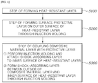
- FIG. 4 illustrates a flowchart of a method of manufacturing a high-pressure vessel according to an embodiment of the present invention.
- the method of manufacturing the high-pressure vessel includes a step S300 of coupling the composite material layer Y with the protective layer Z by attaching the protective layer Z to the outer surface of the composite material layer Y or by forming the shock-absorbing layer L1 between the outer surface of the composite material layer Y and the heat-resistant layer L2 through injection molding or foaming.
- the method may further include a step S200 of forming the surface protective layer L3 on the outer surface of the heat-resistant layer L2 through injection molding or thermoforming.
- the heat-resistant layer L2 may be first formed at step S100, and the surface protective layer L3 may be formed on the outer surface thereof at step S200.
- the surface protective layer L3 may be formed on the outer surface of the heat-resistant layer L2 through injection molding or thermoforming.
- the shock-absorbing layer L1 may be formed on the inner surface of the heat-resistant layer L2 through injection molding or thermoforming to be attached to the outer surface of the composite material layer Y, or the shock-absorbing layer L1 may be directly formed through injection molding or thermoforming on the outer surface of the composite material layer Y at step S300.
- the step S300 of coupling the composite material layer Y with the protective layer Z may be performed by forming the shock-absorbing layer L1 on the inner surface of the heat-resistant layer L2 through injection molding or foaming to form the protective layer Z and then attaching the protective layer to the outer surface of the composite material layer Y, which surrounds the outer surface of the liner (not shown), using an adhesive.
- This may be suitable for coupling the cylinder protecting portion that protects the cylinder portion to the outer surface of the composite material layer Y. In the case of the cylinder portion, it is easy to have a relatively flat surface when winding the composite material layer Y. Thus, required bonding strength between the composite material layer Y and the shock-absorbing layer L1 may be obtained merely by attaching without insert injection.
- the step S300 of coupling the composite material layer Y with the protective layer Z may be performed by placing the heat-resistant layer L2 and the surface protective layer L3 on the outer surface thereof on the outer surface of the composite material layer Y, and forming the shock-absorbing layer L1 of the resin material through injection molding or foaming between the outer surface of the composite material layer Y and the heat-resistant layer L2.
- This may be suitable for coupling the dome protecting portion that protects the dome portion to the outer surface of the composite material layer Y.
- the dome portion since the dome portion has curvature and there is a limit in forming precise curvature when winding the composite material layer Y, it may be difficult to obtain required strength merely by adhesion. Therefore, this is easy to obtain required bonding strength through insert injection.
- the protective layer Z may include the cylinder protecting portion to protect the cylinder portion, and the dome protecting portion to protect the dome portion.
- the cylinder protecting portion may attach the protective layer Z to the outer surface of the composite material layer Y, and the dome protecting portion may form the shock-absorbing layer L1 through injection molding or foaming between the outer surface of the composite material layer Y and the heat-resistant layer L2, thus coupling the composite material layer Y with the protective layer Z.
- FIGS. 5 to 7 illustrate an interface of a protective layer of the high-pressure vessel according to the embodiment of the present invention.
- the surface protective layer L3 may be formed through injection molding or thermoforming to cover the side surface of the heat-resistant layer L2.
- the shock-absorbing layer L1 may be formed through injection molding or foaming to fill a gap between the cylinder protecting portion and the dome protecting portion.
- the heat-resistant layer L2 containing a ceramic material is excellent in heat insulating performance and heat resistance but is vulnerable to moisture. Therefore, the heat-resistant layer L2 is preferably surrounded by the shock-absorbing layer L1 and the surface protective layer L3 so as not to be exposed to the outside.
- the surface protective layer L3 may be formed through injection molding or thermoforming to cover the side surface of the heat-resistant layer L2, or as shown in FIG. 6 , at the step S300 of coupling the composite material layer Y with the protective layer Z, the shock-absorbing layer L1 may be formed through injection molding or foaming to cover the side surface of the heat-resistant layer L2.
- the heat-resistant layer L2 is not exposed to moisture, and is able to sufficiently exhibit heat-resistant effects.
- the protective layer Z may include the cylinder protecting portion to protect the cylinder portion, and the dome protecting portion to protect the dome portion.
- the cylinder protecting portion may attach the protective layer Z to the outer surface of the composite material layer Y, and the dome protecting portion may form the shock-absorbing layer L1 through injection molding or foaming between the outer surface of the composite material layer Y and the heat-resistant layer L2, thus coupling the composite material layer Y with the protective layer Z.
- the dome protecting portion may be coupled to the outer surface of the composite material layer Y by forming the shock-absorbing layer L1 through injection molding or foaming.
- the gap may occur in the process of forming each of a plurality of cylinder protecting portions and dome protecting portions and then coupling the portions to the outer surface of the composite material layer Y, and thus the gap may be filled with the shock-absorbing layer L1 by finally forming the shock-absorbing layer L1 through injection molding or foaming.
- the gap between the cylinder protecting portions may be filled by forming so that there is no gap between surface protective layers L3, and then forming the shock-absorbing layer L1 through injection molding or foaming in the gap between heat-resistant layers L2.
- the gap between the cylinder protecting portion and the dome protecting portion may be filled by forming the shock-absorbing layer L1 through injection molding or foaming in the gap between the surface protective layer L3 and the heat-resistant layer L2, as shown in FIG. 7 .
- the protective layers 200 and 300 composed of the heat-resistant layer and the surface protective layer may include the cylinder protecting portion 200 that protects the cylinder portion, and the dome protecting portion 300 that protects the dome portion.
- the cylinder protecting portion 200 and the dome protecting portion 300 may integrally form the shock-absorbing layer through injection molding or foaming between the outer surface of the composite material layer 100 and the heat-resistant layer, thus coupling the composite material layer 100 with the protective layers 200 and 300.
- the shock-absorbing layer may be integrally formed through injection molding or foaming between the inner surfaces of the protective layers 200 and 300 composed of the heat-resistant layer and the surface protective layer and the outer surface of the composite material layer 100, thus coupling the cylinder protecting portion 200 and the dome protecting portion 300 to the outer surface of the composite material layer 100.
Landscapes
- Engineering & Computer Science (AREA)
- Mechanical Engineering (AREA)
- Manufacturing & Machinery (AREA)
- General Engineering & Computer Science (AREA)
- Filling Or Discharging Of Gas Storage Vessels (AREA)
Applications Claiming Priority (2)
| Application Number | Priority Date | Filing Date | Title |
|---|---|---|---|
| KR1020170121796A KR102043080B1 (ko) | 2017-09-21 | 2017-09-21 | 고압용기 및 그 제조방법 |
| PCT/KR2018/006309 WO2019059495A1 (fr) | 2017-09-21 | 2018-06-01 | Récipient haute pression et procédé pour sa fabrication |
Publications (3)
| Publication Number | Publication Date |
|---|---|
| EP3667152A1 true EP3667152A1 (fr) | 2020-06-17 |
| EP3667152A4 EP3667152A4 (fr) | 2021-05-05 |
| EP3667152B1 EP3667152B1 (fr) | 2023-10-04 |
Family
ID=65810814
Family Applications (1)
| Application Number | Title | Priority Date | Filing Date |
|---|---|---|---|
| EP18858670.5A Active EP3667152B1 (fr) | 2017-09-21 | 2018-06-01 | Récipient haute pression et procédé pour sa fabrication |
Country Status (4)
| Country | Link |
|---|---|
| EP (1) | EP3667152B1 (fr) |
| KR (1) | KR102043080B1 (fr) |
| CN (1) | CN111094832B (fr) |
| WO (1) | WO2019059495A1 (fr) |
Cited By (4)
| Publication number | Priority date | Publication date | Assignee | Title |
|---|---|---|---|---|
| US11654607B2 (en) | 2020-07-08 | 2023-05-23 | Toyota Jidosha Kabushiki Kaisha | Method for manufacturing high pressure tank |
| EP4269860A1 (fr) * | 2022-04-29 | 2023-11-01 | Airbus Operations, S.L.U. | Procédé de fabrication d'un récipient et d'un réservoir à double paroi |
| US11821586B2 (en) * | 2020-10-09 | 2023-11-21 | Toyota Jidosha Kabushiki Kaisha | Manufacturing method of high-pressure tank |
| US20250137599A1 (en) * | 2023-11-01 | 2025-05-01 | Duksan Aetherct Co., Ltd. | Protective cover for shoulder part of pressure vessel |
Families Citing this family (13)
| Publication number | Priority date | Publication date | Assignee | Title |
|---|---|---|---|---|
| KR102869087B1 (ko) * | 2020-03-16 | 2025-10-13 | 현대자동차주식회사 | 압력용기 및 그 제조방법 |
| JP7347360B2 (ja) * | 2020-07-31 | 2023-09-20 | トヨタ自動車株式会社 | タンク及びタンクの製造方法 |
| KR102632593B1 (ko) * | 2021-12-21 | 2024-02-05 | 주식회사 에테르씨티 | 아우터쉘을 구비한 압력용기 |
| KR102746955B1 (ko) * | 2021-12-21 | 2024-12-30 | 덕산에테르씨티 주식회사 | 압력용기의 아우터쉘 장착구조 |
| KR102750425B1 (ko) * | 2022-06-15 | 2025-01-10 | 일진하이솔루스 주식회사 | 내화재 필름이 적층된 수소저장용기 및 그 제조 공정 |
| KR102803991B1 (ko) * | 2022-11-11 | 2025-05-13 | 덕산에테르씨티 주식회사 | 내화성능 및 강도가 보강된 압력용기 |
| KR102815520B1 (ko) * | 2022-11-11 | 2025-06-04 | 덕산에테르씨티 주식회사 | 내화성능 및 강도가 보강된 압력용기 |
| KR102815521B1 (ko) * | 2022-11-11 | 2025-06-04 | 덕산에테르씨티 주식회사 | 내화성능 및 강도가 보강된 압력용기 |
| KR102931036B1 (ko) * | 2022-11-15 | 2026-02-27 | 덕산에테르씨티 주식회사 | 내화패치 및 이를 구비한 압력용기 |
| KR102917063B1 (ko) * | 2023-11-01 | 2026-02-23 | 덕산에테르씨티 주식회사 | 압력 용기의 숄더부 보호용 커버 |
| KR102917061B1 (ko) * | 2023-11-01 | 2026-02-05 | 덕산에테르씨티 주식회사 | 압력 용기의 숄더부 보호용 커버 |
| KR102917062B1 (ko) * | 2023-11-01 | 2026-02-05 | 덕산에테르씨티 주식회사 | 압력 용기의 숄더부 보호용 커버 |
| KR102860820B1 (ko) | 2023-12-04 | 2025-09-17 | 김흥태 | 열팽창 불연 발포폴리우레탄폼으로 성형된 돔 형태의 수소탱크 돔 프로텍터 및 그 제조방법 |
Family Cites Families (22)
| Publication number | Priority date | Publication date | Assignee | Title |
|---|---|---|---|---|
| FR2632051B1 (fr) * | 1988-05-24 | 1990-09-21 | Hembert Claude | Revetement de protection anti-feu et thermique |
| CA1326832C (fr) * | 1987-07-21 | 1994-02-08 | Claude Leon Hembert | Reservoir de fluide et son procede de fabrication |
| US5476189A (en) * | 1993-12-03 | 1995-12-19 | Duvall; Paul F. | Pressure vessel with damage mitigating system |
| JP2000266289A (ja) * | 1999-03-18 | 2000-09-26 | Toyoda Gosei Co Ltd | 圧力容器及びその製造方法 |
| FR2792392B1 (fr) * | 1999-04-19 | 2001-06-29 | Claude Leon Hembert | Dispositif de protection d'un recipient et recipient equipe de ce dispositif |
| GB0020355D0 (en) * | 2000-08-18 | 2000-10-04 | Coniston Holdings Ltd | Moulding methods |
| US8297468B1 (en) * | 2004-05-20 | 2012-10-30 | The United States Of America As Represented By The Administrator Of The National Aeronautics And Space Administration | Fuel tank for liquefied natural gas |
| US20100213198A1 (en) * | 2008-04-18 | 2010-08-26 | Ferus Inc. | Composite structure vessel and transportation system for liquefied gases |
| JP5391281B2 (ja) * | 2009-11-06 | 2014-01-15 | 本田技研工業株式会社 | ガスタンク |
| KR101161229B1 (ko) | 2010-05-07 | 2012-07-02 | 일진컴포지트 주식회사 | 고압용기의 플라스틱 라이너용 이중노즐보스 |
| WO2011159521A2 (fr) * | 2010-06-17 | 2011-12-22 | 3M Innovative Properties Company | Récipients composites résistant à la pression |
| KR20130032186A (ko) * | 2011-09-22 | 2013-04-01 | 국민대학교산학협력단 | 연료 전지 차량용 수소저장탱크 및 그 제조방법 |
| JP5856447B2 (ja) * | 2011-11-17 | 2016-02-09 | サムテック株式会社 | 長尺高圧容器 |
| CN104204649A (zh) * | 2011-12-05 | 2014-12-10 | 蓝波股份有限公司 | 压力容器以及用于将压力容器支承在船舶上的设备 |
| DE102012013937A1 (de) * | 2012-07-16 | 2014-01-16 | Elkamet Kunststofftechnik Gmbh | Druckbehälter und Verfahren zur Herstellung dieses Behälters |
| JP5904081B2 (ja) * | 2012-10-05 | 2016-04-13 | トヨタ自動車株式会社 | 圧力容器およびその生産方法 |
| NL2011888C2 (en) * | 2013-12-04 | 2015-06-08 | Advanced Lightweight Engineering B V | Fibre reinforced pressure vessel and method for forming a fibre reinforced pressure vessel. |
| FR3025584B1 (fr) * | 2014-09-09 | 2017-03-10 | Air Liquide | Recipient composite de conditionnement de gaz comprenant plusieurs enveloppes superposees |
| WO2016162914A1 (fr) * | 2015-04-06 | 2016-10-13 | 大日本印刷株式会社 | Récipient avec étiquetage dans le moule et procédé de fabrication de celui-ci |
| FR3037633B1 (fr) * | 2015-06-18 | 2017-12-01 | L'air Liquide Sa Pour L'etude Et L'exploitation Des Procedes Georges Claude | Reservoir composite et procede de controle et de reparation |
| JP6614180B2 (ja) * | 2017-02-21 | 2019-12-04 | トヨタ自動車株式会社 | 水素タンク素体の製造方法、および水素タンクの製造方法 |
| EP3649393B1 (fr) * | 2017-07-06 | 2022-09-07 | Plastic Omnium New Energies France | Cuve de pression améliorée |
-
2017
- 2017-09-21 KR KR1020170121796A patent/KR102043080B1/ko active Active
-
2018
- 2018-06-01 CN CN201880060925.1A patent/CN111094832B/zh active Active
- 2018-06-01 EP EP18858670.5A patent/EP3667152B1/fr active Active
- 2018-06-01 WO PCT/KR2018/006309 patent/WO2019059495A1/fr not_active Ceased
Cited By (5)
| Publication number | Priority date | Publication date | Assignee | Title |
|---|---|---|---|---|
| US11654607B2 (en) | 2020-07-08 | 2023-05-23 | Toyota Jidosha Kabushiki Kaisha | Method for manufacturing high pressure tank |
| US11821586B2 (en) * | 2020-10-09 | 2023-11-21 | Toyota Jidosha Kabushiki Kaisha | Manufacturing method of high-pressure tank |
| EP4269860A1 (fr) * | 2022-04-29 | 2023-11-01 | Airbus Operations, S.L.U. | Procédé de fabrication d'un récipient et d'un réservoir à double paroi |
| US12377623B2 (en) | 2022-04-29 | 2025-08-05 | Airbus Operations S.L.U. | Method for manufacturing a vessel and a double-wall tank |
| US20250137599A1 (en) * | 2023-11-01 | 2025-05-01 | Duksan Aetherct Co., Ltd. | Protective cover for shoulder part of pressure vessel |
Also Published As
| Publication number | Publication date |
|---|---|
| WO2019059495A1 (fr) | 2019-03-28 |
| EP3667152A4 (fr) | 2021-05-05 |
| KR20190033676A (ko) | 2019-04-01 |
| EP3667152B1 (fr) | 2023-10-04 |
| CN111094832B (zh) | 2022-04-08 |
| KR102043080B1 (ko) | 2019-11-12 |
| CN111094832A (zh) | 2020-05-01 |
Similar Documents
| Publication | Publication Date | Title |
|---|---|---|
| EP3667152B1 (fr) | Récipient haute pression et procédé pour sa fabrication | |
| CN102939496B (zh) | 高压罐及高压罐的制造方法 | |
| US8931661B2 (en) | Structure and manufacturing method for pressure vessel | |
| US10465848B1 (en) | Conformable composite pressure vessel | |
| CN111188990B (zh) | 高压罐及其安装构造 | |
| UA129085C2 (uk) | Напірна ємність з пластиковим вкладишем | |
| US10422477B2 (en) | Composite vessel assembly and method of manufacture | |
| EP3446026B1 (fr) | Ensemble de cuve sous pression composite et procédé de fabrication | |
| US11529780B2 (en) | Manufacturing method for high-pressure tank | |
| US20200247070A1 (en) | High-pressure tank and method of manufacturing the same | |
| US11926109B2 (en) | Method of manufacturing a composite vessel assembly | |
| EP3380777B1 (fr) | Ensemble cuve sous pression composite et procédé de fabrication | |
| US20210095818A1 (en) | Restraining structure for structural object | |
| JP6781581B2 (ja) | 車両の非シリンダ型複合材圧力容器 | |
| EP3380775B1 (fr) | Ensemble récipient sous pression composite à élément chauffant intégré | |
| KR102885478B1 (ko) | 압력용기 및 압력용기의 제조방법 | |
| JP2017166545A (ja) | 高圧タンク | |
| CN217441355U (zh) | 燃气桶 | |
| JP7131523B2 (ja) | モジュール | |
| KR20250075785A (ko) | 다공성 구조의 내충격 부재를 구비한 고압 용기 및 그 제조방법 | |
| KR20250174136A (ko) | 기밀성이 향상된 라이너리스 압력용기 |
Legal Events
| Date | Code | Title | Description |
|---|---|---|---|
| STAA | Information on the status of an ep patent application or granted ep patent |
Free format text: STATUS: THE INTERNATIONAL PUBLICATION HAS BEEN MADE |
|
| PUAI | Public reference made under article 153(3) epc to a published international application that has entered the european phase |
Free format text: ORIGINAL CODE: 0009012 |
|
| STAA | Information on the status of an ep patent application or granted ep patent |
Free format text: STATUS: REQUEST FOR EXAMINATION WAS MADE |
|
| 17P | Request for examination filed |
Effective date: 20200313 |
|
| AK | Designated contracting states |
Kind code of ref document: A1 Designated state(s): AL AT BE BG CH CY CZ DE DK EE ES FI FR GB GR HR HU IE IS IT LI LT LU LV MC MK MT NL NO PL PT RO RS SE SI SK SM TR |
|
| AX | Request for extension of the european patent |
Extension state: BA ME |
|
| DAV | Request for validation of the european patent (deleted) | ||
| DAX | Request for extension of the european patent (deleted) | ||
| A4 | Supplementary search report drawn up and despatched |
Effective date: 20210409 |
|
| RIC1 | Information provided on ipc code assigned before grant |
Ipc: F17C 1/16 20060101AFI20210401BHEP Ipc: F17C 13/00 20060101ALI20210401BHEP Ipc: B29C 45/16 20060101ALI20210401BHEP |
|
| GRAP | Despatch of communication of intention to grant a patent |
Free format text: ORIGINAL CODE: EPIDOSNIGR1 |
|
| STAA | Information on the status of an ep patent application or granted ep patent |
Free format text: STATUS: GRANT OF PATENT IS INTENDED |
|
| INTG | Intention to grant announced |
Effective date: 20230502 |
|
| GRAS | Grant fee paid |
Free format text: ORIGINAL CODE: EPIDOSNIGR3 |
|
| GRAA | (expected) grant |
Free format text: ORIGINAL CODE: 0009210 |
|
| STAA | Information on the status of an ep patent application or granted ep patent |
Free format text: STATUS: THE PATENT HAS BEEN GRANTED |
|
| AK | Designated contracting states |
Kind code of ref document: B1 Designated state(s): AL AT BE BG CH CY CZ DE DK EE ES FI FR GB GR HR HU IE IS IT LI LT LU LV MC MK MT NL NO PL PT RO RS SE SI SK SM TR |
|
| REG | Reference to a national code |
Ref country code: GB Ref legal event code: FG4D |
|
| REG | Reference to a national code |
Ref country code: CH Ref legal event code: EP |
|
| REG | Reference to a national code |
Ref country code: IE Ref legal event code: FG4D |
|
| REG | Reference to a national code |
Ref country code: DE Ref legal event code: R096 Ref document number: 602018058878 Country of ref document: DE |
|
| REG | Reference to a national code |
Ref country code: LT Ref legal event code: MG9D |
|
| REG | Reference to a national code |
Ref country code: NL Ref legal event code: MP Effective date: 20231004 |
|
| REG | Reference to a national code |
Ref country code: AT Ref legal event code: MK05 Ref document number: 1618064 Country of ref document: AT Kind code of ref document: T Effective date: 20231004 |
|
| PG25 | Lapsed in a contracting state [announced via postgrant information from national office to epo] |
Ref country code: NL Free format text: LAPSE BECAUSE OF FAILURE TO SUBMIT A TRANSLATION OF THE DESCRIPTION OR TO PAY THE FEE WITHIN THE PRESCRIBED TIME-LIMIT Effective date: 20231004 |
|
| PG25 | Lapsed in a contracting state [announced via postgrant information from national office to epo] |
Ref country code: GR Free format text: LAPSE BECAUSE OF FAILURE TO SUBMIT A TRANSLATION OF THE DESCRIPTION OR TO PAY THE FEE WITHIN THE PRESCRIBED TIME-LIMIT Effective date: 20240105 |
|
| PG25 | Lapsed in a contracting state [announced via postgrant information from national office to epo] |
Ref country code: IS Free format text: LAPSE BECAUSE OF FAILURE TO SUBMIT A TRANSLATION OF THE DESCRIPTION OR TO PAY THE FEE WITHIN THE PRESCRIBED TIME-LIMIT Effective date: 20240204 |
|
| PG25 | Lapsed in a contracting state [announced via postgrant information from national office to epo] |
Ref country code: LT Free format text: LAPSE BECAUSE OF FAILURE TO SUBMIT A TRANSLATION OF THE DESCRIPTION OR TO PAY THE FEE WITHIN THE PRESCRIBED TIME-LIMIT Effective date: 20231004 |
|
| PG25 | Lapsed in a contracting state [announced via postgrant information from national office to epo] |
Ref country code: AT Free format text: LAPSE BECAUSE OF FAILURE TO SUBMIT A TRANSLATION OF THE DESCRIPTION OR TO PAY THE FEE WITHIN THE PRESCRIBED TIME-LIMIT Effective date: 20231004 |
|
| PG25 | Lapsed in a contracting state [announced via postgrant information from national office to epo] |
Ref country code: ES Free format text: LAPSE BECAUSE OF FAILURE TO SUBMIT A TRANSLATION OF THE DESCRIPTION OR TO PAY THE FEE WITHIN THE PRESCRIBED TIME-LIMIT Effective date: 20231004 |
|
| PG25 | Lapsed in a contracting state [announced via postgrant information from national office to epo] |
Ref country code: LT Free format text: LAPSE BECAUSE OF FAILURE TO SUBMIT A TRANSLATION OF THE DESCRIPTION OR TO PAY THE FEE WITHIN THE PRESCRIBED TIME-LIMIT Effective date: 20231004 Ref country code: IS Free format text: LAPSE BECAUSE OF FAILURE TO SUBMIT A TRANSLATION OF THE DESCRIPTION OR TO PAY THE FEE WITHIN THE PRESCRIBED TIME-LIMIT Effective date: 20240204 Ref country code: GR Free format text: LAPSE BECAUSE OF FAILURE TO SUBMIT A TRANSLATION OF THE DESCRIPTION OR TO PAY THE FEE WITHIN THE PRESCRIBED TIME-LIMIT Effective date: 20240105 Ref country code: ES Free format text: LAPSE BECAUSE OF FAILURE TO SUBMIT A TRANSLATION OF THE DESCRIPTION OR TO PAY THE FEE WITHIN THE PRESCRIBED TIME-LIMIT Effective date: 20231004 Ref country code: BG Free format text: LAPSE BECAUSE OF FAILURE TO SUBMIT A TRANSLATION OF THE DESCRIPTION OR TO PAY THE FEE WITHIN THE PRESCRIBED TIME-LIMIT Effective date: 20240104 Ref country code: AT Free format text: LAPSE BECAUSE OF FAILURE TO SUBMIT A TRANSLATION OF THE DESCRIPTION OR TO PAY THE FEE WITHIN THE PRESCRIBED TIME-LIMIT Effective date: 20231004 Ref country code: PT Free format text: LAPSE BECAUSE OF FAILURE TO SUBMIT A TRANSLATION OF THE DESCRIPTION OR TO PAY THE FEE WITHIN THE PRESCRIBED TIME-LIMIT Effective date: 20240205 |
|
| PG25 | Lapsed in a contracting state [announced via postgrant information from national office to epo] |
Ref country code: SE Free format text: LAPSE BECAUSE OF FAILURE TO SUBMIT A TRANSLATION OF THE DESCRIPTION OR TO PAY THE FEE WITHIN THE PRESCRIBED TIME-LIMIT Effective date: 20231004 Ref country code: RS Free format text: LAPSE BECAUSE OF FAILURE TO SUBMIT A TRANSLATION OF THE DESCRIPTION OR TO PAY THE FEE WITHIN THE PRESCRIBED TIME-LIMIT Effective date: 20231004 Ref country code: PL Free format text: LAPSE BECAUSE OF FAILURE TO SUBMIT A TRANSLATION OF THE DESCRIPTION OR TO PAY THE FEE WITHIN THE PRESCRIBED TIME-LIMIT Effective date: 20231004 Ref country code: NO Free format text: LAPSE BECAUSE OF FAILURE TO SUBMIT A TRANSLATION OF THE DESCRIPTION OR TO PAY THE FEE WITHIN THE PRESCRIBED TIME-LIMIT Effective date: 20240104 Ref country code: LV Free format text: LAPSE BECAUSE OF FAILURE TO SUBMIT A TRANSLATION OF THE DESCRIPTION OR TO PAY THE FEE WITHIN THE PRESCRIBED TIME-LIMIT Effective date: 20231004 Ref country code: HR Free format text: LAPSE BECAUSE OF FAILURE TO SUBMIT A TRANSLATION OF THE DESCRIPTION OR TO PAY THE FEE WITHIN THE PRESCRIBED TIME-LIMIT Effective date: 20231004 |
|
| REG | Reference to a national code |
Ref country code: DE Ref legal event code: R097 Ref document number: 602018058878 Country of ref document: DE |
|
| PG25 | Lapsed in a contracting state [announced via postgrant information from national office to epo] |
Ref country code: DK Free format text: LAPSE BECAUSE OF FAILURE TO SUBMIT A TRANSLATION OF THE DESCRIPTION OR TO PAY THE FEE WITHIN THE PRESCRIBED TIME-LIMIT Effective date: 20231004 |
|
| PG25 | Lapsed in a contracting state [announced via postgrant information from national office to epo] |
Ref country code: CZ Free format text: LAPSE BECAUSE OF FAILURE TO SUBMIT A TRANSLATION OF THE DESCRIPTION OR TO PAY THE FEE WITHIN THE PRESCRIBED TIME-LIMIT Effective date: 20231004 |
|
| PG25 | Lapsed in a contracting state [announced via postgrant information from national office to epo] |
Ref country code: SK Free format text: LAPSE BECAUSE OF FAILURE TO SUBMIT A TRANSLATION OF THE DESCRIPTION OR TO PAY THE FEE WITHIN THE PRESCRIBED TIME-LIMIT Effective date: 20231004 |
|
| PG25 | Lapsed in a contracting state [announced via postgrant information from national office to epo] |
Ref country code: SM Free format text: LAPSE BECAUSE OF FAILURE TO SUBMIT A TRANSLATION OF THE DESCRIPTION OR TO PAY THE FEE WITHIN THE PRESCRIBED TIME-LIMIT Effective date: 20231004 Ref country code: SK Free format text: LAPSE BECAUSE OF FAILURE TO SUBMIT A TRANSLATION OF THE DESCRIPTION OR TO PAY THE FEE WITHIN THE PRESCRIBED TIME-LIMIT Effective date: 20231004 Ref country code: RO Free format text: LAPSE BECAUSE OF FAILURE TO SUBMIT A TRANSLATION OF THE DESCRIPTION OR TO PAY THE FEE WITHIN THE PRESCRIBED TIME-LIMIT Effective date: 20231004 Ref country code: IT Free format text: LAPSE BECAUSE OF FAILURE TO SUBMIT A TRANSLATION OF THE DESCRIPTION OR TO PAY THE FEE WITHIN THE PRESCRIBED TIME-LIMIT Effective date: 20231004 Ref country code: EE Free format text: LAPSE BECAUSE OF FAILURE TO SUBMIT A TRANSLATION OF THE DESCRIPTION OR TO PAY THE FEE WITHIN THE PRESCRIBED TIME-LIMIT Effective date: 20231004 Ref country code: DK Free format text: LAPSE BECAUSE OF FAILURE TO SUBMIT A TRANSLATION OF THE DESCRIPTION OR TO PAY THE FEE WITHIN THE PRESCRIBED TIME-LIMIT Effective date: 20231004 Ref country code: CZ Free format text: LAPSE BECAUSE OF FAILURE TO SUBMIT A TRANSLATION OF THE DESCRIPTION OR TO PAY THE FEE WITHIN THE PRESCRIBED TIME-LIMIT Effective date: 20231004 |
|
| PLBE | No opposition filed within time limit |
Free format text: ORIGINAL CODE: 0009261 |
|
| STAA | Information on the status of an ep patent application or granted ep patent |
Free format text: STATUS: NO OPPOSITION FILED WITHIN TIME LIMIT |
|
| 26N | No opposition filed |
Effective date: 20240705 |
|
| PG25 | Lapsed in a contracting state [announced via postgrant information from national office to epo] |
Ref country code: SI Free format text: LAPSE BECAUSE OF FAILURE TO SUBMIT A TRANSLATION OF THE DESCRIPTION OR TO PAY THE FEE WITHIN THE PRESCRIBED TIME-LIMIT Effective date: 20231004 |
|
| PG25 | Lapsed in a contracting state [announced via postgrant information from national office to epo] |
Ref country code: SI Free format text: LAPSE BECAUSE OF FAILURE TO SUBMIT A TRANSLATION OF THE DESCRIPTION OR TO PAY THE FEE WITHIN THE PRESCRIBED TIME-LIMIT Effective date: 20231004 |
|
| PG25 | Lapsed in a contracting state [announced via postgrant information from national office to epo] |
Ref country code: MC Free format text: LAPSE BECAUSE OF FAILURE TO SUBMIT A TRANSLATION OF THE DESCRIPTION OR TO PAY THE FEE WITHIN THE PRESCRIBED TIME-LIMIT Effective date: 20231004 |
|
| REG | Reference to a national code |
Ref country code: CH Ref legal event code: PL |
|
| PG25 | Lapsed in a contracting state [announced via postgrant information from national office to epo] |
Ref country code: LU Free format text: LAPSE BECAUSE OF NON-PAYMENT OF DUE FEES Effective date: 20240601 |
|
| GBPC | Gb: european patent ceased through non-payment of renewal fee |
Effective date: 20240601 |
|
| PG25 | Lapsed in a contracting state [announced via postgrant information from national office to epo] |
Ref country code: IE Free format text: LAPSE BECAUSE OF NON-PAYMENT OF DUE FEES Effective date: 20240601 |
|
| PG25 | Lapsed in a contracting state [announced via postgrant information from national office to epo] |
Ref country code: BE Free format text: LAPSE BECAUSE OF NON-PAYMENT OF DUE FEES Effective date: 20240630 Ref country code: CH Free format text: LAPSE BECAUSE OF NON-PAYMENT OF DUE FEES Effective date: 20240630 |
|
| PG25 | Lapsed in a contracting state [announced via postgrant information from national office to epo] |
Ref country code: FR Free format text: LAPSE BECAUSE OF NON-PAYMENT OF DUE FEES Effective date: 20240630 |
|
| PG25 | Lapsed in a contracting state [announced via postgrant information from national office to epo] |
Ref country code: GB Free format text: LAPSE BECAUSE OF NON-PAYMENT OF DUE FEES Effective date: 20240601 |
|
| REG | Reference to a national code |
Ref country code: BE Ref legal event code: MM Effective date: 20240630 |
|
| PG25 | Lapsed in a contracting state [announced via postgrant information from national office to epo] |
Ref country code: CY Free format text: LAPSE BECAUSE OF FAILURE TO SUBMIT A TRANSLATION OF THE DESCRIPTION OR TO PAY THE FEE WITHIN THE PRESCRIBED TIME-LIMIT; INVALID AB INITIO Effective date: 20180601 |
|
| PG25 | Lapsed in a contracting state [announced via postgrant information from national office to epo] |
Ref country code: FI Free format text: LAPSE BECAUSE OF FAILURE TO SUBMIT A TRANSLATION OF THE DESCRIPTION OR TO PAY THE FEE WITHIN THE PRESCRIBED TIME-LIMIT Effective date: 20231004 |
|
| PGFP | Annual fee paid to national office [announced via postgrant information from national office to epo] |
Ref country code: DE Payment date: 20250630 Year of fee payment: 8 |
|
| PG25 | Lapsed in a contracting state [announced via postgrant information from national office to epo] |
Ref country code: HU Free format text: LAPSE BECAUSE OF FAILURE TO SUBMIT A TRANSLATION OF THE DESCRIPTION OR TO PAY THE FEE WITHIN THE PRESCRIBED TIME-LIMIT; INVALID AB INITIO Effective date: 20180601 |