EP3667687A1 - Spannsystem für einen elektrischen transformator - Google Patents
Spannsystem für einen elektrischen transformator Download PDFInfo
- Publication number
- EP3667687A1 EP3667687A1 EP18211824.0A EP18211824A EP3667687A1 EP 3667687 A1 EP3667687 A1 EP 3667687A1 EP 18211824 A EP18211824 A EP 18211824A EP 3667687 A1 EP3667687 A1 EP 3667687A1
- Authority
- EP
- European Patent Office
- Prior art keywords
- clamping
- clamping frame
- frame member
- bridge
- transformer
- Prior art date
- Legal status (The legal status is an assumption and is not a legal conclusion. Google has not performed a legal analysis and makes no representation as to the accuracy of the status listed.)
- Withdrawn
Links
Images


Classifications
-
- H—ELECTRICITY
- H01—ELECTRIC ELEMENTS
- H01F—MAGNETS; INDUCTANCES; TRANSFORMERS; SELECTION OF MATERIALS FOR THEIR MAGNETIC PROPERTIES
- H01F27/00—Details of transformers or inductances, in general
- H01F27/24—Magnetic cores
- H01F27/26—Fastening parts of the core together; Fastening or mounting the core on casing or support
- H01F27/263—Fastening parts of the core together
Definitions
- the invention relates to clamping system for a transformer, the clamping system comprising a first clamping frame with a first clamping frame member and a second clamping frame member adapted to be arranged on opposing sides of a laminated yoke of a transformer core of said transformer, as well as at least one tension element, preferably at least one horizontal tie bar and/or at least one tensioning bandage, connecting the first clamping frame member to the second clamping frame member under tensile stress.
- Electrical transformers and electrical power transformers in particular usually feature a transformer core consisting of multiple laminations. Windings of a particular phase are arranged on each core column of this laminated core.
- the ends of said core columns are connected by yokes of the laminated core; upper ends of the columns are connected to each other by an upper yoke whereas lower ends of the columns are connected to each other by a lower yoke.
- clamping frames are employed which are attached to the upper and lower yokes of the laminated core. Respective members of these clamping frames are positioned on opposing sides of the yoke and are held together under tension, such that the respective yoke is wedged in between said clamping frame members.
- each winding is pressed between two pressure plates which are inserted between the upper yoke and the upper ending of the winding, and between the lower yoke and the lower end of the winding respectively.
- the clamping frame assigned to the upper yoke is connected to the clamping frame assigned to the lower yoke via tension elements. After pressing the clamping frames assigned to the upper and lower yoke towards each other, the clamping frames are firmly attached to the tension elements such that said tension elements keep the distance between both clamping frames fixed.
- Known clamping frames are made of magnetic steel grade (EN 10025 S235xx or S355xx) and therefore the members of each clamping frame form an electrically connected loop. Electromagnetic fields originating from the windings and connection thus generate eddy currents in the whole clamping frame. This may result in stray losses, the creation of hotspots within the active part of the transformer, and may also lead to gassing as well as to high stray losses. Moreover, known clamping frames significantly increase the total weight of the transformer due to the material they are made of.
- the proposed clamping frame should minimize losses and heat or gassing problems stemming from eddy currents in the transformer's clamping system, and at the same time facilitate a significant reduction in weight as compared to known clamping systems.
- the clamping system comprising a first clamping frame with
- clamping frame By employing epoxy resin (laminate), the clamping frame's weight is significantly decreased. Moreover, due to the employment of an electrically insulating material, the clamping frame no longer allows eddy currents to freely flow through it. Thus, additional elements for electric isolation, as they are employed in the prior art, become moot and any effects attributed to eddy currents prevailing in the clamping frame can be effectively minimized or avoided. At the same time, clamping frames made of epoxy resin (laminate) have structural strength and stability properties facilitating to reliably keep the laminated yoke in shape and position when pressure is exerted on the first and second clamping frame members.
- the epoxy resin laminate is realized as epoxy woven glass cloth.
- Such a material provides the clamping frame with optimal electric isolation and structural properties (e.g. sufficient stiffness) and thereby greatly improves the overall stability of the whole clamping system and at the same time reduces stray losses in the clamping system.
- the epoxy woven glass cloth is EP GC 203 or EP GC 205, as defined in the norm IEC 60893.
- a clamping frame made of this material is strong enough to maintain stability of the clamping system as well as of the transformer's laminated core under stress, and in addition to that provides excellent isolation in order to reduce negative effects associated with eddy currents through the clamping frame.
- the first clamping frame comprises at least one clamping bridge adapted to connect the first clamping frame member to the second clamping frame member such that the laminated yoke is at least partially covered by the clamping bridge.
- the clamping frame comprises a clamping bridge.
- the clamping bridge When external pressure is applied on the clamping frame, the clamping bridge will retain the respective yoke thereby avoiding that the yoke is lifted from its position and/or that the respective core laminations deform under pressure.
- the clamping system comprises a further clamping frame and at least two further tension elements, preferably at least two vertical tie bars, connecting the first clamping frame to the further clamping frame of the clamping system, whereas these tension elements are received in a corresponding set of openings of the clamping bridge.
- the set of openings for receiving the further tension elements for connecting the first clamping frame to the further clamping frame may be positioned in a first and second mounting portion of the clamping bridge, whereas these mounting portions facilitate the connection between the clamping bridge and the first and second clamping frame members.
- the openings can be realized as drilled holes.
- said openings can be supported by one or more support discs or support plates. Said openings allow for a particularly simple and reliable way of receiving the further tension elements for connecting the first clamping frame member and/or the second clamping frame member to the further clamping frame. While pressure is applied to the first clamping frame (i.e.
- these further tension elements may be loosely inserted in the openings, thereby allowing for a variation of the distance between the first clamping frame and the further clamping frame.
- the further tension elements may be tightly fastened to the clamping bridge, e.g. by means of threaded heads of the further tension elements and corresponding nuts.
- lifting protrusions of the further tension elements protrude beyond the clamping bridge, preferably beyond a surface of the clamping bridge.
- the clamping frame members normally feature special fastening eyes which are mounted on the first clamping frame member and the second clamping frame member of the first clamping frame.
- each member has two fastening eyes.
- the active part of known transformers can be lifted, provided that the clamping frame members sufficiently support the fastening eyes and the weight of the active part.
- the clamping frame members according to the invention are, however, not made of steel - as in the state of the art - but of epoxy resin (laminate), such fastening eyes would not be properly supported due to the structural properties of the material.
- the further tension elements are provided with lifting protrusions.
- the lifting protrusions which may form the ends of each further tension element, the further tension elements protrude beyond the clamping bridge.
- the lifting protrusions may be realised as specifically strengthened end sections of the further tension elements, e.g. as threaded heads of the further tension elements.
- the clamping bridge is made of epoxy resin, preferably of epoxy resin laminate, and the openings are lined with reinforcing members, preferably realized as glass fibre tubes.
- the clamping bridge of this embodiment may have a tendency to delaminate, e.g. due to threaded heads of the tension elements and/or of fastening elements used to fix the clamping bridge to the clamping frame members. Under pressure the threads might eat into the inner walls of the openings of the clamping bridge. In order to prevent this, the inner walls of the openings may be reinforced by means of said reinforcing members.
- Fig. 1 shows a clamping system according to the invention. As such it comprises a first clamping frame 16 which is arranged on an upper yoke 7 of a laminated core 8 of an electric transformer, as well as a further clamping frame 17, which is, however, not depicted in Fig. 1 but only an arrow indicating its position is shown.
- the further clamping frame 17 is identical to the first clamping frame 16 and is arranged on a lower yoke of the same laminated core 8.
- the first clamping frame 16 comprises a first clamping frame member 5 arranged on one side of the yoke 7, as well as a second clamping frame member 6 arranged on an a side of the yoke 7 opposite of the first clamping frame member 5.
- the first clamping frame member 5 and the second clamping frame member 6 are connected to each other under tensile stress by means of one or more tension elements, which may be realized as horizontal tie bars 19 (see Fig. 2 ), and/or outside tensioning bandages 23, and/or winding side tensioning element 24 (see Fig. 1 ). Due to these tension elements, said first clamping frame 16 exerts a force on the yoke 7 pressing its laminations against each other thereby holding the yoke 7 together.
- the first clamping frame member 5 and/or the second camping frame member 6 is/are made of epoxy resin or epoxy resin laminate. This choice of material prevents eddy currents to be induced in the clamping frame 16, thereby avoiding negative effects like power losses, gassing or hotspots. Moreover, the weight of the clamping frame 16 is significantly less than the weight of known clamping frames.
- a clamping bridge 1 is mounted on both clamping frame members 5, 6 such that it partially covers the yoke 7. Since the clamping bridge 1 may be made of epoxy resin or of epoxy resin laminate, no eddy currents can be induced in the clamping bridge, which thus further contributes to the above-mentioned positive effects of the clamping system according to the invention; on the other hand the clamping bridge 1 features sufficient structural strength to fulfil its purpose, namely to retain the position of most or all of the laminations and thereby the shape of the yoke 7 when pressure is applied to the first clamping frame 16, e.g. during winding pressing.
- Said clamping bridge 1 comprises a first mounting portion 2 for mounting the clamping bridge 1 on the first clamping frame member 5, as well as a second mounting portion 3 for mounting the clamping bridge 1 on the second clamping frame member 6.
- the clamping bridge 1 is placed on the clamping frame members 5, 6 such that the fist mounting portion 2 at least partially overlaps with the first clamping frame member 5 and that the second mounting portion 3 at least partially overlaps with the second clamping frame member 6.
- fastening elements 14 see Fig. 3
- the first mounting portion 2 is fixed to the first clamping frame member 5 and the second mounting portion 3 is fixed to the second clamping frame member 6.
- the first mounting portion 2 and the second mounting portion 3 have a first set of openings 12 which themselves are realized as elongated holes that are open towards the sides of the clamping bridge 1.
- the clamping bridge 1 also comprises a retaining portion 4 (see Fig. 2 ) which is adapted to be brought into contact with the yoke 7.
- Said retaining portion 4 comprises a first planar section 9, which is arranged in a plane different from a plane in which the first mounting portion 2 and the second mounting portion 3 are positioned.
- Said first planar section 9 is connected to the first mounting portion 2 by means of a second planar section 10 protruding obliquely from the first planar section 9. The transition from the first planar section 9 to the second planar section 10, as well from the second planar section 10 to the first mounting portion 2 may be facilitated by kinked or bent sections of the retaining portion 4.
- said first planar section 9 is connected to the second mounting portion 3 by means of a third planar section 11 protruding obliquely from the first planar section 9.
- the transition from the first planar section 9 to the third planar section 11, as well from the third planar section 11 to the second mounting portion 3 may be facilitated by kinked or bent sections of the retaining portion 4.
- the retaining portion 4 of the clamping bridge 1 resembles the structure of the yoke 7 in good approximation.
- the yoke 7 is assembled out of multiple laminations having different height.
- a surface of the yoke 7 facing the clamping bridge 1 is uneven due to laminations having different height.
- the corresponding profile of the yoke 7 has a maximum height in a central region with its height falling off in outer regions of said surface.
- the clamping bridge 1 allows to retain the position of most or all of the laminations and thereby the entire shape of the yoke 7 when pressure is applied to the first clamping frame 16 during the procedure of winding pressing.
- first clamping frame 16 which conveys said external pressure to windings of the transformer arranged on core columns between the upper yoke 7 and the lower yoke.
- first clamping frame 16 and the further clamping frame 17, which is attributed to the lower yoke are loosely connected such that their distance may still be varied.
- further tension elements which can be realized as vertical tie bars 20, are foreseen which can be tightly fixed to the further clamping frame 17 but at first are inserted only loosely into a corresponding set of openings, i.e. the second set of openings 13, of the first clamping frame 16.
- said second set of openings 13 is arranged in the clamping bridge 1, in particular in the first mounting portion 2 and the second mounting portion 3 of the clamping bridge 1.
- the openings of said se cond set of openings 13 are realized as bore holes which in Fig. 2 and 3 are covered by support plates 21 aiding with the stability of the mounting portions 2, 3 when the vertical tie bars 20 are tightly fixed to the clamping bridge 1.
- the positions of the second set of openings 13 may directly and unambiguously be deferred from the position of the upper ends of the vertical tie bars 20 serving as tension elements 15 for connecting the first clamping frame 16 to the further clamping frame 17.
- the vertical tie bars 20 are tightly fixed to the first clamping frame 16 by means of threaded nuts 22 tightened against the support plates 21.
- the relative positions of the first clamping frame 16 and the second clamping frame 17 are fixed and the distance between the clamping frames 16, 17 cannot be varied any longer.
- the pressure on the windings is maintained without the external pressure having to be exerted any longer on the first clamping frame 16.
- the vertical tie bars 20 are provided with lifting protrusions 15. With these lifting protrusions 15, which may form the ends of each vertical tie bar 20, the vertical tie bars 20 protrude beyond the clamping bridge 1.
- the lifting protrusions 15 may be realised as specifically strengthened end sections of the further tension elements, e.g. as threaded heads of the vertical tie bars 20.
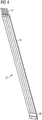
- Fig. 4 shows an embodiment of the vertical tie bar 20. It comprises several, here four, tie plates 25, each of which terminates at one end in a corresponding lifting protrusion 15.
- the lifting protrusion 15 is realized as threaded projections for securing a nut and for connecting the vertical tie bar 20 with a lifting beam or a lifting structure of the lifting device.
- the tie plate 25 changes to a rectangular cross section, e.g. 50x10 flats.
- a single weld on pad 26 connects the individual tie plates 25 to each other.
- the structure of the vertical tie bar 20 shown in Fig. 4 is particularly chosen to accommodate the number of tie plates 25 (which is based on the winding clamping force and short circuit force) within a core circle to have an optimum filling of the core in a given core circle diameter.
- the number of tie plates 25 will change based on stresses arising in these plates during pressing, lifting and special operating conditions like short circuit situation for each transformer. Therefore, the number of projections at the top of each vertical tie bar 20 will be based on size of the transformer and the prevailing forces.
- the inner walls of the first set of openings 12 and/or of the second set of openings 13 are lined with reinforcing members 18 which are preferably realized as glass fibre tubes.
Landscapes
- Engineering & Computer Science (AREA)
- Power Engineering (AREA)
- Housings And Mounting Of Transformers (AREA)
Priority Applications (2)
| Application Number | Priority Date | Filing Date | Title |
|---|---|---|---|
| EP18211824.0A EP3667687A1 (de) | 2018-12-12 | 2018-12-12 | Spannsystem für einen elektrischen transformator |
| PCT/EP2019/083607 WO2020120244A1 (en) | 2018-12-12 | 2019-12-04 | Clamping system for an electric transformer |
Applications Claiming Priority (1)
| Application Number | Priority Date | Filing Date | Title |
|---|---|---|---|
| EP18211824.0A EP3667687A1 (de) | 2018-12-12 | 2018-12-12 | Spannsystem für einen elektrischen transformator |
Publications (1)
| Publication Number | Publication Date |
|---|---|
| EP3667687A1 true EP3667687A1 (de) | 2020-06-17 |
Family
ID=64664962
Family Applications (1)
| Application Number | Title | Priority Date | Filing Date |
|---|---|---|---|
| EP18211824.0A Withdrawn EP3667687A1 (de) | 2018-12-12 | 2018-12-12 | Spannsystem für einen elektrischen transformator |
Country Status (2)
| Country | Link |
|---|---|
| EP (1) | EP3667687A1 (de) |
| WO (1) | WO2020120244A1 (de) |
Cited By (2)
| Publication number | Priority date | Publication date | Assignee | Title |
|---|---|---|---|---|
| EP4006927A1 (de) * | 2020-11-30 | 2022-06-01 | Hitachi Energy Switzerland AG | Laminierte nicht-magnetische verbindungsplatte für transformatorkerne |
| US20230274871A1 (en) * | 2020-08-06 | 2023-08-31 | Hitachi Energy Switzerland Ag | Transformer core and transformer |
Families Citing this family (1)
| Publication number | Priority date | Publication date | Assignee | Title |
|---|---|---|---|---|
| DE102020214854A1 (de) | 2020-11-26 | 2022-06-02 | Siemens Energy Global GmbH & Co. KG | Pressrahmen für ein Joch eines Transformatorkerns |
Citations (4)
| Publication number | Priority date | Publication date | Assignee | Title |
|---|---|---|---|---|
| DE2339972A1 (de) * | 1973-06-25 | 1975-01-16 | Bbc Brown Boveri & Cie | Abstuetz- bzw. pressvorrichtung fuer magnetkerne und wicklungen von transformatoren oder drosselspulen |
| WO2000002211A1 (de) * | 1998-07-02 | 2000-01-13 | Siemens Aktiengesellschaft | Induktives bauteil mit einem kern |
| CN102543384B (zh) * | 2010-12-20 | 2016-02-03 | 沈阳福林特种变压器有限公司 | 矿用隔爆型移动变电站用非晶合金铁芯全绝缘干式变压器 |
| CN206758242U (zh) * | 2017-06-08 | 2017-12-15 | 济南西门子变压器有限公司 | 电力变压器 |
-
2018
- 2018-12-12 EP EP18211824.0A patent/EP3667687A1/de not_active Withdrawn
-
2019
- 2019-12-04 WO PCT/EP2019/083607 patent/WO2020120244A1/en not_active Ceased
Patent Citations (4)
| Publication number | Priority date | Publication date | Assignee | Title |
|---|---|---|---|---|
| DE2339972A1 (de) * | 1973-06-25 | 1975-01-16 | Bbc Brown Boveri & Cie | Abstuetz- bzw. pressvorrichtung fuer magnetkerne und wicklungen von transformatoren oder drosselspulen |
| WO2000002211A1 (de) * | 1998-07-02 | 2000-01-13 | Siemens Aktiengesellschaft | Induktives bauteil mit einem kern |
| CN102543384B (zh) * | 2010-12-20 | 2016-02-03 | 沈阳福林特种变压器有限公司 | 矿用隔爆型移动变电站用非晶合金铁芯全绝缘干式变压器 |
| CN206758242U (zh) * | 2017-06-08 | 2017-12-15 | 济南西门子变压器有限公司 | 电力变压器 |
Cited By (3)
| Publication number | Priority date | Publication date | Assignee | Title |
|---|---|---|---|---|
| US20230274871A1 (en) * | 2020-08-06 | 2023-08-31 | Hitachi Energy Switzerland Ag | Transformer core and transformer |
| EP4006927A1 (de) * | 2020-11-30 | 2022-06-01 | Hitachi Energy Switzerland AG | Laminierte nicht-magnetische verbindungsplatte für transformatorkerne |
| WO2022111901A1 (en) * | 2020-11-30 | 2022-06-02 | Hitachi Energy Switzerland Ag | Tie plate for a transformer core assembly |
Also Published As
| Publication number | Publication date |
|---|---|
| WO2020120244A1 (en) | 2020-06-18 |
Similar Documents
| Publication | Publication Date | Title |
|---|---|---|
| EP3667687A1 (de) | Spannsystem für einen elektrischen transformator | |
| JPS60769B2 (ja) | 誘導電気装置 | |
| CN106158284B (zh) | 一种树脂浇注线圈干式变压器结构及其装配方法 | |
| EP2430643B1 (de) | Transformator mit abgeschirmten klemmen | |
| JP2024506149A (ja) | 巻線体、高電圧巻線及び乾式変圧器 | |
| KR102768703B1 (ko) | 지진 적용을 위한 변압기 코일 블록 디자인 | |
| EP3667686A1 (de) | Klemmbrücke und klemmsystem für einen elektrischen transormator | |
| EP2187408A1 (de) | Eisenkernreaktor | |
| US20200312517A1 (en) | Potting box and transformer | |
| KR20160052214A (ko) | 변압기의 타이플레이트 구조 | |
| KR101695345B1 (ko) | 비결정질 코어를 가지는 전력 변압기 | |
| US10833537B2 (en) | Coil unit | |
| KR20140112028A (ko) | 변압기 코어 | |
| US20040037056A1 (en) | Ruggedized inverter chassis | |
| US20200312516A1 (en) | Transformer | |
| US20200312547A1 (en) | Transformer and assembling method thereof | |
| CN114631160B (zh) | 用于空气扼流线圈和变压器的补偿块 | |
| CN101226816B (zh) | 环氧浇注干式减振降噪铁心并联电抗器 | |
| CN114373610B (zh) | 一种低压串联电抗器 | |
| EP4222762A1 (de) | Strukturelle anordnung zur befestigung von leiterwickelpaketen in einem luftkernreaktor | |
| US12400782B2 (en) | Structural arrangement for attachment of a standoff insulator to an air core reactor | |
| JPS62279611A (ja) | 変圧器鉄心支持装置 | |
| CN112735811A (zh) | 阻尼电容器固定机构和换流阀阻尼电容器组及其安装方法 | |
| CN213519545U (zh) | 一种稳固的移相变压器 | |
| EP3751588B1 (de) | Elektrischer transformator |
Legal Events
| Date | Code | Title | Description |
|---|---|---|---|
| PUAI | Public reference made under article 153(3) epc to a published international application that has entered the european phase |
Free format text: ORIGINAL CODE: 0009012 |
|
| STAA | Information on the status of an ep patent application or granted ep patent |
Free format text: STATUS: THE APPLICATION HAS BEEN PUBLISHED |
|
| AK | Designated contracting states |
Kind code of ref document: A1 Designated state(s): AL AT BE BG CH CY CZ DE DK EE ES FI FR GB GR HR HU IE IS IT LI LT LU LV MC MK MT NL NO PL PT RO RS SE SI SK SM TR |
|
| AX | Request for extension of the european patent |
Extension state: BA ME |
|
| STAA | Information on the status of an ep patent application or granted ep patent |
Free format text: STATUS: REQUEST FOR EXAMINATION WAS MADE |
|
| 17P | Request for examination filed |
Effective date: 20201217 |
|
| RAP1 | Party data changed (applicant data changed or rights of an application transferred) |
Owner name: SIEMENS ENERGY GLOBAL GMBH & CO. KG |
|
| RBV | Designated contracting states (corrected) |
Designated state(s): AL AT BE BG CH CY CZ DE DK EE ES FI FR GB GR HR HU IE IS IT LI LT LU LV MC MK MT NL NO PL PT RO RS SE SI SK SM TR |
|
| STAA | Information on the status of an ep patent application or granted ep patent |
Free format text: STATUS: EXAMINATION IS IN PROGRESS |
|
| 17Q | First examination report despatched |
Effective date: 20220323 |
|
| STAA | Information on the status of an ep patent application or granted ep patent |
Free format text: STATUS: THE APPLICATION IS DEEMED TO BE WITHDRAWN |
|
| 18D | Application deemed to be withdrawn |
Effective date: 20220803 |