EP4006927A1 - Laminierte nicht-magnetische verbindungsplatte für transformatorkerne - Google Patents
Laminierte nicht-magnetische verbindungsplatte für transformatorkerne Download PDFInfo
- Publication number
- EP4006927A1 EP4006927A1 EP20210766.0A EP20210766A EP4006927A1 EP 4006927 A1 EP4006927 A1 EP 4006927A1 EP 20210766 A EP20210766 A EP 20210766A EP 4006927 A1 EP4006927 A1 EP 4006927A1
- Authority
- EP
- European Patent Office
- Prior art keywords
- tie plate
- transformer core
- core assembly
- yoke
- plate
- Prior art date
- Legal status (The legal status is an assumption and is not a legal conclusion. Google has not performed a legal analysis and makes no representation as to the accuracy of the status listed.)
- Pending
Links
Images

Classifications
-
- H—ELECTRICITY
- H01—ELECTRIC ELEMENTS
- H01F—MAGNETS; INDUCTANCES; TRANSFORMERS; SELECTION OF MATERIALS FOR THEIR MAGNETIC PROPERTIES
- H01F27/00—Details of transformers or inductances, in general
- H01F27/24—Magnetic cores
- H01F27/26—Fastening parts of the core together; Fastening or mounting the core on casing or support
- H01F27/263—Fastening parts of the core together
-
- H—ELECTRICITY
- H01—ELECTRIC ELEMENTS
- H01F—MAGNETS; INDUCTANCES; TRANSFORMERS; SELECTION OF MATERIALS FOR THEIR MAGNETIC PROPERTIES
- H01F27/00—Details of transformers or inductances, in general
- H01F27/34—Special means for preventing or reducing unwanted electric or magnetic effects, e.g. no-load losses, reactive currents, harmonics, oscillations, leakage fields
Definitions
- the present disclosure relates to a transformer core assembly comprising a tie plate and to a tie plate for use with a transformer core assembly.
- a transformer is a passive electrical device that transfers electrical energy from one electrical circuit to another, or to multiple circuits.
- a typical transformer comprises a ferromagnetic core having several, e.g., three parallel limbs, which are often oriented vertically, extending between a first or bottom yoke and a second or top yoke. Coils or windings are wounded around the limbs. A varying current in any one of the windings produces a varying magnetic flux in the core, which induces a varying electromotive force across any other winding wound around the core.
- the core is a laminated construction made from a plurality of stacked core sheets.
- the transformer further comprises two first or bottom yoke clamping plates for clamping the core sheets within a section of the core forming the bottom yoke, from two opposite sides, and two second or top yoke clamping plates for clamping the core sheets within a section of the core forming the top yoke.
- the transformer comprises an elongate tie plate positioned next to and parallel to a limb.
- the tie plate is fixed, usually via a welding connection, with one end to one of the bottom yoke clamping plates and with its other end to one of the top yoke clamping plates.
- the tie plate generally has one or more of the following functions:
- a tie plate generally shall consume a minimum of the available cross section inside the winding. Therefore, the tie plate is usually made from high strength, magnetic steel. This kind of material is comparatively cheap and shows an appropriate strength.
- transformers are exposed to non-alternating currents, i.e. direct currents, e.g., by an increasing use of power electronics which may cause a direct current bias magnetization which in turn causes saturation of the magnetic transformer core. Excess magnetic flux is thereby pushed into the magnetic tie plate where it causes excessive eddy current heating. This particularly reduces effectiveness of the transformer assembly and additionally requires increased cooling.
- non-magnetic steel instead of magnetic steel for manufacturing a tie plate is disadvantageous insofar as most of the non-magnetic steels have merely about half of the mechanical strength of a magnetic high strength steel. Therefore, such a non-magnetic steel tie plate would need to have a significantly enlarged thickness compared to a tie plate made from magnetic high strength steel in order to obtain a certain degree of mechanical strength. Moreover, non-magnetic steels are typically more expensive than magnetic steels.
- An increase in mechanical strength can generally be effectuated by work hardening (cold deformation) of non-magnetic austenitic steel.
- welding processes for attaching a tie plate made of such a material to the yoke clamping plates may mechanically weaken the material, at least locally.
- carbon or glass fiber materials have sufficient tensile strength, but far too much elongation.
- a transformer core assembly comprising a first yoke clamping plate for clamping a first yoke of a transformer core, and a second yoke clamping plate for clamping a second yoke of the transformer core. Further, the transformer core assembly comprises a plurality of stacked sheets forming a tie plate.
- the tie plate has a first end and a second end, wherein the first end is connected to the first yoke clamping plate and the second end is connected to the second yoke clamping plate.
- Using stacked sheets for forming the tie plate significantly improves the quality of the tie plate.
- To build up a tie plate from a plurality of stacked sheets has proven to be advantageous both as regards mechanical properties of the resulting tie plate as well as regards production thereof.
- tie plate there is an increased availability of suited materials for manufacturing the tie plate.
- high manganese steel material having an adequate, high tensile strength which has proven particularly suitable.
- this material can be welded with only a moderate reduction of the tensile strength.
- this material is comparatively cheap.
- a tie plate typically has a thickness between 12 and 15 mm and the high manganese steel material is hard to obtain in this thickness range in the relevant - comparatively small - amount typically used for transformer core assemblies.
- a thinner gauge of this material within a few Millimeters, is readily available on the market on coils.
- using stacked sheets of a corresponding gauge for forming the tie plate allows for providing a tie plate having adequate tensile strength at moderate cost, showing improved producibility.
- the at least one of the stacked sheets may be of a non-magnetic composition.
- transformers may be exposed to non-alternating currents, causing a direct current bias magnetization which in turn causes saturation of the magnetic transformer core. Excess magnetic flux is thereby pushed into the magnetic tie plate where it causes excessive eddy current heating. This particularly reduces effectiveness of the transformer assembly and additionally requires increased cooling. Accordingly, using a non-magnetic composition for manufacturing at least one of the stacked sheets allows for an improvement of the effectiveness of the transformer core assembly.
- the non-magnetic composition may be high manganese steel.
- the advantages of manganese steel have already been pointed out above.
- the non-magnetic composition may be for example austenitic steel, particularly work-hardened austenitic steel. This kind of material is generally readily available, non-magnetic and showing an adequate tensile strength.
- a material for manufacturing a tie plate should have a high tensile strength and a low elongation. It has been found that the so called “third generation advanced high strength steel” (3 rd GEN AHSS) described therein, namely steels having a tensile strength from about 800MPa and more and up to 2000MPa and more while having a low elongation, for example of about between about 5% and 39% may be used as material for manufacturing the sheets (both new and current generation). These steels are characterized by their high manganese content, for example 15 to 30%.
- the sheets may have a thickness between 0,5 mm and 6 mm, for example between 1 mm and 4 mm.
- the sheets may be connected to each other by a plurality of welding spots and/or a plurality of bolts. Welding spots as opposed to welding seams or the like have proven advantageous since disadvantageous effects of welding are thereby reduced to a minimum.
- the sheets may be connected to each other for example by an adhesive. Such connection may be durable or just serve for relative fixation of the sheets to allow manufacture of holes through the sheets, as discussed below.
- the tie plate may have a thickness between 10 mm and 20 mm, for example between 12 mm and 15 mm.
- the tie plate may include a plurality of holes configured for positioning an attachment member, for example in form of a bolt or a pin, for attaching (i) the tie plate to the first and second yoke clamping plates and/or (ii) for attaching the plurality of sheets to one another for forming the tie plate.
- an attachment member for example in form of a bolt or a pin
- Using a bolt or a pin having a smooth cylindrical surface for contacting the inner side of a corresponding hole is advantageous since this allows for a particularly good load transfer.
- bolts without a thread may be used as attachment members, or bolts having a thread only at an end region which is not designed or intended to be positioned within a hole.
- the tie plate may be elongate, extending along a longitudinal axis, wherein the holes are formed in a series along the longitudinal axis of the tie plate. This allows for an improved matching of the shear strength of the attachment members and the tensile strength of the sheet material between the holes at a minimum overall width of the tie plate. Thereby, as much as possible of the tensile strength of the sheet material can be effectively used.
- the plurality of holes may be laser beam cut, or water jet cut or machined. Machining the holes makes it possible to obtain holes having particularly smooth load bearing surfaces on its inner sides. This is particularly suited if un-threated bolts are used as attachment members.
- the tie plate may be manufactured by connecting the sheets together, e.g., by welding spots, and subsequently machining the holes. Thus, the sheets are kept aligned adequately by the welding spots during the machining process.
- the sheets may be attached to one another for example by an adhesive.
- the tie plate may comprise at least one slot.
- a tie plate is exposed to an electromagnetic fringe field from the windings. Especially in the region near the top and bottom winding ends this magnetic field has a strong component perpendicular to the core and to the tie plate which generates eddy currents flowing in a plane defined by the tie plate. These eddy currents cause losses which heat the tie plate. Therefore, providing the tie plate with at least one slot allows for reducing eddy current losses and avoiding or at least reducing local hot spots. Moreover, such a slot provides a path for an insulating fluid to cool the tie plate.
- the tie plate may have a width between 20 mm and 80 mm, for example between 30 mm and 75 mm.
- a tie plate for use with a transformer core assembly comprising a plurality of stacked sheets.
- the at least one of the stacked sheets may be of a non-magnetic composition.
- the non-magnetic composition may be high manganese steel or austenitic steel.
- the tie plate may include a plurality of holes configured for positioning an attachment member for attaching (i) the tie plate first and second yoke clamping plates and/or (ii) for attaching the plurality of sheets to one another for forming the tie plate.
- the present disclosure comprises the following aspects:
- Fig. 1 a is a schematic side view of a transformer core assembly according to the present disclosure. Unless otherwise indicated, the transformer core assembly may be designed as described above in the background section.
- the transformer core assembly comprises a transformer core 1 having a limb 2, extending along a longitudinal axis L, a first or bottom yoke 8 and a second or top yoke 10.
- the core 1 may further have at least one more limb 2', 2".
- the limb 2 may be oriented vertically.
- the core 1 may be composed by a plurality of laminated core sheets as known as such in the art.
- the transformer core assembly further comprises two first yoke clamping plates 14 for clamping the core sheets within a section of the core 1 forming the first yoke 8, from two opposite sides, and two second yoke clamping plates 16 for clamping the core sheets within a section of the core 1 forming the second yoke 10.
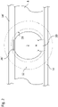
- Fig. 2 shows a schematic cross-section through the limb 2.
- the parts are illustrated in an exploded manner, i.e. distances between adjacent parts are depicted which do not exist or which are exaggerated in order to improve visibility.
- the first yoke clamping plates 14, 14' are arranged at two opposite sides of the first yoke 8.
- the first yoke clamping plates 14, 14' are positioned such that they compress the first yoke 8.
- the second yoke clamping plates 16 are designed and arranged correspondingly.
- the transformer core assembly further comprises an elongate tie plate 20, extending along a longitudinal axis L2.
- the tie plate 20 has a first end 22 and a second end 24.
- the first end 22 is fixedly connected to a first one of the first yoke clamping plates 14, 14'.
- the second end 24 is analogously connected to a first one of the second yoke clamping plates 16.
- a winding 12 is wound around the limb 2.
- the tie plate 20 is positioned next to and parallel to the limb 2.
- the tie plate 20 may be positioned at least partly between the limb 2 and the winding 12.
- the tie plate 20 may extend substantially parallel to the limb axis L.
- the tie plate 20 may contact the limb 2.
- a thin electrically insulating sheet (not shown in Fig. 2 ) may be disposed between the tie plate 20 and the limb 2.
- the electrically insulating sheet may have a thickness of between 1 and 20 mm, for example between 1 mm and 10 mm.
- the tie plate 20 is positioned at least partly between the limb 2 and an inner side 18 of the winding 12.
- the tie plate 20 may protrude with its first end 22 and its second end 24 from the winding 12. Further windings (not shown in Figures 1 and 2 ) may be correspondingly wound around each of the at least one more limb 2', 2".
- a further tie plate 20' may be provided next to the limb 2, attached to a second one of the first yoke clamping plates and to a second one to the second yoke clamping plates analogously.
- press rings 32, 34 are mounted at top and bottom of the winding block. These press rings 32, 34 are resting against the bottom and top yoke clamping plates 14, 16.
- a large electromagnetic force may be produced in the windings during an external fault in an electric network to which the transformer is connectable.
- Such a force may typically act in an axial direction of the limb 2.
- the tie plate 20 is designed and arranged to take such a force.
- the tie plate 20 may be designed to have the functionality outlined above in the background section.
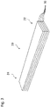
- the tie plate 20 is formed by a plurality of stacked sheets 30, as schematically illustrated in Fig. 3 .
- the stacked sheets 30 are of a non-magnetic composition, for example in the form of a high manganese steel material.
- the high manganese steel may have a manganese content between 20 % by mass and 30 % by mass, for example between 21 % by mass and 28 % by mass, or for example between 22 % by mass and 26 % by mass.
- the non-magnetic composition alternatively may be austenitic steel.
- the austenitic steel may be work hardened.
- the thickness of at least one of the sheets 30 or all of the sheets 30 may be within a few Millimeters, e.g., between 0.5 mm and 6 mm or between 1 mm and 4 mm. All the stacked sheets 30 may have the same thickness.
- the overall thickness of the tie plate 20 may be between 10 mm and 20 mm, for example between 12 mm and 15 mm.
- the stacked sheets 30 may be connected to each other by a plurality of welding spots.
- the stacked sheets 30 may be connected to each other by a plurality of bolts.
- the stacked sheets 30 may be connected to each other by an adhesive.
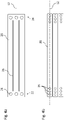
- the tie plate 20 may have a plurality of holes 26 configured for positioning an attachment member (not shown in the Figures).
- the plurality of holes 26 may be configured for positioning an attachment member and/or for positioning the tie plate 20 relative to an attachment member for attaching (i) the tie plate 20 to the first yoke clamping plate 14 and the second yoke clamping plate 16 and/or for attaching the plurality of sheets 30 to one another for forming the tie plate 20.
- the attachment member may be for example a bolt or a pin.
- the tie plate 20 may be manufactured by welding the sheets 30 together and by subsequently machining the holes 26. Machining the holes 26 allows for producing the holes 26 such that they show smooth inner surfaces.
- the tie plate 20 may comprise at least one slot 28, particularly a longitudinal slot 28, for example extending parallel to the longitudinal axis L2 of the tie plate 20.
- the tie plate 20 may comprise one or more slots 28, at least one slot 28 extending along the entire length or at least 80% of the entire length of the tie plate 20.
- the tie plate 20 may have a plurality of holes 26 formed in a series along the longitudinal axis L2 of the tie plate 20, and/or parallel to the longitudinal axis L2 of the tie plate 20, for example such that centers of the holes 26 are located along a straight line parallel to or coinciding with the longitudinal axis L2.
- a series of holes 26 is advantageous vis-à-vis the design of Fig. 4a , since shear strength of the bolts can be better matched.
- the holes 26 may be laser beam cut, water jet cut, machined or punched.
- tie plates can be used positioned adjacent to and parallel to one another side by side to mechanically support the limb 2.
- the width w of the tie plate 20 may be between 20 mm and 80 mm, for example between 30 mm and 75 mm, its length between 1 m and 5 m. While the present disclosure has been described in detail in the drawings and forgoing description, such description is to be considered illustrative or exemplary and not restrictive. Variations to the disclosed embodiments can be understood and effected by those skilled in the art and practicing the claimed subject-matter, from a study of the drawings, the disclosure, and the appended claims. In the claims, the word “comprising” does not exclude other elements, and the indefinite article "a” or “an” does not exclude a plurality. The mere fact that certain elements or steps are recited in distinct claims does not indicate that a combination of these elements or steps cannot be used to advantage, specifically, in addition to the actual claim dependency, any further meaningful claim combination shall be considered disclosed.
Landscapes
- Engineering & Computer Science (AREA)
- Power Engineering (AREA)
- Manufacturing Cores, Coils, And Magnets (AREA)
Priority Applications (5)
| Application Number | Priority Date | Filing Date | Title |
|---|---|---|---|
| EP20210766.0A EP4006927A1 (de) | 2020-11-30 | 2020-11-30 | Laminierte nicht-magnetische verbindungsplatte für transformatorkerne |
| KR1020237007417A KR20230036164A (ko) | 2020-11-30 | 2021-10-12 | 변압기 코어 조립체용 타이 플레이트 |
| PCT/EP2021/078101 WO2022111901A1 (en) | 2020-11-30 | 2021-10-12 | Tie plate for a transformer core assembly |
| CN202180054943.0A CN116075908A (zh) | 2020-11-30 | 2021-10-12 | 用于变压器芯组件的拉板 |
| US18/022,191 US20230317346A1 (en) | 2020-11-30 | 2021-10-12 | Tie plate for a transformer core assembly |
Applications Claiming Priority (1)
| Application Number | Priority Date | Filing Date | Title |
|---|---|---|---|
| EP20210766.0A EP4006927A1 (de) | 2020-11-30 | 2020-11-30 | Laminierte nicht-magnetische verbindungsplatte für transformatorkerne |
Publications (1)
| Publication Number | Publication Date |
|---|---|
| EP4006927A1 true EP4006927A1 (de) | 2022-06-01 |
Family
ID=73646264
Family Applications (1)
| Application Number | Title | Priority Date | Filing Date |
|---|---|---|---|
| EP20210766.0A Pending EP4006927A1 (de) | 2020-11-30 | 2020-11-30 | Laminierte nicht-magnetische verbindungsplatte für transformatorkerne |
Country Status (5)
| Country | Link |
|---|---|
| US (1) | US20230317346A1 (de) |
| EP (1) | EP4006927A1 (de) |
| KR (1) | KR20230036164A (de) |
| CN (1) | CN116075908A (de) |
| WO (1) | WO2022111901A1 (de) |
Citations (10)
| Publication number | Priority date | Publication date | Assignee | Title |
|---|---|---|---|---|
| US3349357A (en) * | 1965-08-31 | 1967-10-24 | Gen Electric | Transformer core reinforcing plate |
| US3614695A (en) * | 1970-09-24 | 1971-10-19 | Westinghouse Canada Ltd | Inductive apparatus with magnetic locking plates |
| CN201156464Y (zh) * | 2007-12-05 | 2008-11-26 | 中国西电电气股份有限公司 | 一种变压器铁心拉板 |
| CN203250628U (zh) * | 2013-05-28 | 2013-10-23 | 浙江临高电气实业有限公司 | 用于变压器中的铁芯拉板结构及包含该拉板结构的变压器 |
| CN103506746B (zh) * | 2013-09-27 | 2015-09-30 | 保定天威电气设备结构有限公司 | 一种变压器夹件拉板隔磁槽的防变形加工方法及专用工具 |
| CN205230804U (zh) * | 2015-12-28 | 2016-05-11 | 保定天威保变电气股份有限公司 | 现场组装变压器铁芯拉板装配结构 |
| KR20160052214A (ko) * | 2014-11-04 | 2016-05-12 | 엘에스산전 주식회사 | 변압기의 타이플레이트 구조 |
| CN205428654U (zh) * | 2015-09-28 | 2016-08-03 | 江苏华辰变压器有限公司 | 干式变压器拉板绝缘增强结构 |
| CN205723104U (zh) * | 2016-06-23 | 2016-11-23 | 山东达驰电气有限公司 | 一种变压器用拉板 |
| EP3667687A1 (de) * | 2018-12-12 | 2020-06-17 | Siemens Aktiengesellschaft | Spannsystem für einen elektrischen transformator |
Family Cites Families (3)
| Publication number | Priority date | Publication date | Assignee | Title |
|---|---|---|---|---|
| US3753187A (en) * | 1969-08-11 | 1973-08-14 | Allegheny Ludlum Ind Inc | Electrical device casing materials |
| JP6460329B2 (ja) * | 2015-02-27 | 2019-01-30 | 株式会社オートネットワーク技術研究所 | リアクトル |
| US9978500B2 (en) * | 2016-07-18 | 2018-05-22 | Virginia Transformer Corporation | Yoke clamp component for a transformer core |
-
2020
- 2020-11-30 EP EP20210766.0A patent/EP4006927A1/de active Pending
-
2021
- 2021-10-12 US US18/022,191 patent/US20230317346A1/en active Pending
- 2021-10-12 WO PCT/EP2021/078101 patent/WO2022111901A1/en not_active Ceased
- 2021-10-12 CN CN202180054943.0A patent/CN116075908A/zh active Pending
- 2021-10-12 KR KR1020237007417A patent/KR20230036164A/ko not_active Ceased
Patent Citations (10)
| Publication number | Priority date | Publication date | Assignee | Title |
|---|---|---|---|---|
| US3349357A (en) * | 1965-08-31 | 1967-10-24 | Gen Electric | Transformer core reinforcing plate |
| US3614695A (en) * | 1970-09-24 | 1971-10-19 | Westinghouse Canada Ltd | Inductive apparatus with magnetic locking plates |
| CN201156464Y (zh) * | 2007-12-05 | 2008-11-26 | 中国西电电气股份有限公司 | 一种变压器铁心拉板 |
| CN203250628U (zh) * | 2013-05-28 | 2013-10-23 | 浙江临高电气实业有限公司 | 用于变压器中的铁芯拉板结构及包含该拉板结构的变压器 |
| CN103506746B (zh) * | 2013-09-27 | 2015-09-30 | 保定天威电气设备结构有限公司 | 一种变压器夹件拉板隔磁槽的防变形加工方法及专用工具 |
| KR20160052214A (ko) * | 2014-11-04 | 2016-05-12 | 엘에스산전 주식회사 | 변압기의 타이플레이트 구조 |
| CN205428654U (zh) * | 2015-09-28 | 2016-08-03 | 江苏华辰变压器有限公司 | 干式变压器拉板绝缘增强结构 |
| CN205230804U (zh) * | 2015-12-28 | 2016-05-11 | 保定天威保变电气股份有限公司 | 现场组装变压器铁芯拉板装配结构 |
| CN205723104U (zh) * | 2016-06-23 | 2016-11-23 | 山东达驰电气有限公司 | 一种变压器用拉板 |
| EP3667687A1 (de) * | 2018-12-12 | 2020-06-17 | Siemens Aktiengesellschaft | Spannsystem für einen elektrischen transformator |
Also Published As
| Publication number | Publication date |
|---|---|
| WO2022111901A1 (en) | 2022-06-02 |
| KR20230036164A (ko) | 2023-03-14 |
| CN116075908A (zh) | 2023-05-05 |
| US20230317346A1 (en) | 2023-10-05 |
Similar Documents
| Publication | Publication Date | Title |
|---|---|---|
| US20190157921A1 (en) | Magnetic plate laminate, manufacturing method therefor, and motor using this laminate | |
| WO2012011389A1 (ja) | リアクトル装置 | |
| EP4006927A1 (de) | Laminierte nicht-magnetische verbindungsplatte für transformatorkerne | |
| US6611191B2 (en) | Transformer | |
| US20180268985A1 (en) | Ac reactor | |
| KR102427376B1 (ko) | 전자석, 전자 개폐기, 및 전자석의 제조 방법 | |
| JP5828132B2 (ja) | リアクタ | |
| CA2597934A1 (en) | Transformer core with magnetic screening | |
| JPH0864428A (ja) | 積層鉄心及びその組立方法 | |
| CN2035929U (zh) | 电动机的叠片定子 | |
| JP5900741B2 (ja) | 複合磁心、リアクトルおよび電源装置 | |
| US2145703A (en) | Shell type transformer | |
| CN210110465U (zh) | 电感器 | |
| JP5869305B2 (ja) | 溶接トランスおよびその製造方法 | |
| US6570479B2 (en) | Laminated transformer system and method | |
| JP3096267U (ja) | 内鉄型リアクトル | |
| JPS6339930Y2 (de) | ||
| JP3362433B2 (ja) | コイル部品 | |
| CN220933879U (zh) | 一种变压器铁芯结构 | |
| JP2015141997A (ja) | リアクトルコアおよびこれを用いたリアクトル | |
| CN211859745U (zh) | 一种电动振动台的外磁极 | |
| JP2011103365A (ja) | リアクトル | |
| JPS5996852A (ja) | 積層コアの形成方法 | |
| JPH0113397Y2 (de) | ||
| KR19980024451A (ko) | 마그네트척 |
Legal Events
| Date | Code | Title | Description |
|---|---|---|---|
| PUAI | Public reference made under article 153(3) epc to a published international application that has entered the european phase |
Free format text: ORIGINAL CODE: 0009012 |
|
| STAA | Information on the status of an ep patent application or granted ep patent |
Free format text: STATUS: THE APPLICATION HAS BEEN PUBLISHED |
|
| AK | Designated contracting states |
Kind code of ref document: A1 Designated state(s): AL AT BE BG CH CY CZ DE DK EE ES FI FR GB GR HR HU IE IS IT LI LT LU LV MC MK MT NL NO PL PT RO RS SE SI SK SM TR |
|
| STAA | Information on the status of an ep patent application or granted ep patent |
Free format text: STATUS: REQUEST FOR EXAMINATION WAS MADE |
|
| 17P | Request for examination filed |
Effective date: 20220808 |
|
| RBV | Designated contracting states (corrected) |
Designated state(s): AL AT BE BG CH CY CZ DE DK EE ES FI FR GB GR HR HU IE IS IT LI LT LU LV MC MK MT NL NO PL PT RO RS SE SI SK SM TR |
|
| P01 | Opt-out of the competence of the unified patent court (upc) registered |
Effective date: 20230527 |
|
| RAP1 | Party data changed (applicant data changed or rights of an application transferred) |
Owner name: HITACHI ENERGY LTD |
|
| STAA | Information on the status of an ep patent application or granted ep patent |
Free format text: STATUS: EXAMINATION IS IN PROGRESS |
|
| 17Q | First examination report despatched |
Effective date: 20231220 |