EP3668292A1 - Dispositif inverseur ayant un mécanisme de dissipation de chaleur - Google Patents
Dispositif inverseur ayant un mécanisme de dissipation de chaleur Download PDFInfo
- Publication number
- EP3668292A1 EP3668292A1 EP19184862.1A EP19184862A EP3668292A1 EP 3668292 A1 EP3668292 A1 EP 3668292A1 EP 19184862 A EP19184862 A EP 19184862A EP 3668292 A1 EP3668292 A1 EP 3668292A1
- Authority
- EP
- European Patent Office
- Prior art keywords
- heat dissipation
- heat
- inverter device
- mechanism according
- dissipation mechanism
- Prior art date
- Legal status (The legal status is an assumption and is not a legal conclusion. Google has not performed a legal analysis and makes no representation as to the accuracy of the status listed.)
- Granted
Links
Images




Classifications
-
- H—ELECTRICITY
- H02—GENERATION; CONVERSION OR DISTRIBUTION OF ELECTRIC POWER
- H02M—APPARATUS FOR CONVERSION BETWEEN AC AND AC, BETWEEN AC AND DC, OR BETWEEN DC AND DC, AND FOR USE WITH MAINS OR SIMILAR POWER SUPPLY SYSTEMS; CONVERSION OF DC OR AC INPUT POWER INTO SURGE OUTPUT POWER; CONTROL OR REGULATION THEREOF
- H02M7/00—Conversion of AC power input into DC power output; Conversion of DC power input into AC power output
- H02M7/003—Constructional details, e.g. physical layout, assembly, wiring or busbar connections
-
- H—ELECTRICITY
- H05—ELECTRIC TECHNIQUES NOT OTHERWISE PROVIDED FOR
- H05K—PRINTED CIRCUITS; CASINGS OR CONSTRUCTIONAL DETAILS OF ELECTRIC APPARATUS; MANUFACTURE OF ASSEMBLAGES OF ELECTRICAL COMPONENTS
- H05K1/00—Printed circuits
- H05K1/02—Details
- H05K1/14—Structural association of two or more printed circuits
-
- H—ELECTRICITY
- H05—ELECTRIC TECHNIQUES NOT OTHERWISE PROVIDED FOR
- H05K—PRINTED CIRCUITS; CASINGS OR CONSTRUCTIONAL DETAILS OF ELECTRIC APPARATUS; MANUFACTURE OF ASSEMBLAGES OF ELECTRICAL COMPONENTS
- H05K1/00—Printed circuits
- H05K1/18—Printed circuits structurally associated with non-printed electric components
- H05K1/181—Printed circuits structurally associated with non-printed electric components associated with surface mounted components
-
- H—ELECTRICITY
- H05—ELECTRIC TECHNIQUES NOT OTHERWISE PROVIDED FOR
- H05K—PRINTED CIRCUITS; CASINGS OR CONSTRUCTIONAL DETAILS OF ELECTRIC APPARATUS; MANUFACTURE OF ASSEMBLAGES OF ELECTRICAL COMPONENTS
- H05K5/00—Casings, cabinets or drawers for electric apparatus
- H05K5/02—Details
- H05K5/03—Covers
-
- H—ELECTRICITY
- H05—ELECTRIC TECHNIQUES NOT OTHERWISE PROVIDED FOR
- H05K—PRINTED CIRCUITS; CASINGS OR CONSTRUCTIONAL DETAILS OF ELECTRIC APPARATUS; MANUFACTURE OF ASSEMBLAGES OF ELECTRICAL COMPONENTS
- H05K7/00—Constructional details common to different types of electric apparatus
- H05K7/14—Mounting supporting structure in casing or on frame or rack
- H05K7/1422—Printed circuit boards receptacles, e.g. stacked structures, electronic circuit modules or box like frames
- H05K7/1427—Housings
-
- H—ELECTRICITY
- H05—ELECTRIC TECHNIQUES NOT OTHERWISE PROVIDED FOR
- H05K—PRINTED CIRCUITS; CASINGS OR CONSTRUCTIONAL DETAILS OF ELECTRIC APPARATUS; MANUFACTURE OF ASSEMBLAGES OF ELECTRICAL COMPONENTS
- H05K7/00—Constructional details common to different types of electric apparatus
- H05K7/20—Modifications to facilitate cooling, ventilating, or heating
- H05K7/20009—Modifications to facilitate cooling, ventilating, or heating using a gaseous coolant in electronic enclosures
- H05K7/20136—Forced ventilation, e.g. by fans
-
- H—ELECTRICITY
- H05—ELECTRIC TECHNIQUES NOT OTHERWISE PROVIDED FOR
- H05K—PRINTED CIRCUITS; CASINGS OR CONSTRUCTIONAL DETAILS OF ELECTRIC APPARATUS; MANUFACTURE OF ASSEMBLAGES OF ELECTRICAL COMPONENTS
- H05K7/00—Constructional details common to different types of electric apparatus
- H05K7/20—Modifications to facilitate cooling, ventilating, or heating
- H05K7/20009—Modifications to facilitate cooling, ventilating, or heating using a gaseous coolant in electronic enclosures
- H05K7/20136—Forced ventilation, e.g. by fans
- H05K7/20154—Heat dissipaters coupled to components
-
- H—ELECTRICITY
- H05—ELECTRIC TECHNIQUES NOT OTHERWISE PROVIDED FOR
- H05K—PRINTED CIRCUITS; CASINGS OR CONSTRUCTIONAL DETAILS OF ELECTRIC APPARATUS; MANUFACTURE OF ASSEMBLAGES OF ELECTRICAL COMPONENTS
- H05K7/00—Constructional details common to different types of electric apparatus
- H05K7/20—Modifications to facilitate cooling, ventilating, or heating
- H05K7/20009—Modifications to facilitate cooling, ventilating, or heating using a gaseous coolant in electronic enclosures
- H05K7/20136—Forced ventilation, e.g. by fans
- H05K7/20172—Fan mounting or fan specifications
-
- H—ELECTRICITY
- H05—ELECTRIC TECHNIQUES NOT OTHERWISE PROVIDED FOR
- H05K—PRINTED CIRCUITS; CASINGS OR CONSTRUCTIONAL DETAILS OF ELECTRIC APPARATUS; MANUFACTURE OF ASSEMBLAGES OF ELECTRICAL COMPONENTS
- H05K7/00—Constructional details common to different types of electric apparatus
- H05K7/20—Modifications to facilitate cooling, ventilating, or heating
- H05K7/20009—Modifications to facilitate cooling, ventilating, or heating using a gaseous coolant in electronic enclosures
- H05K7/202—Air circulating in closed loop within enclosure wherein heat is removed through heat-exchangers
-
- H—ELECTRICITY
- H05—ELECTRIC TECHNIQUES NOT OTHERWISE PROVIDED FOR
- H05K—PRINTED CIRCUITS; CASINGS OR CONSTRUCTIONAL DETAILS OF ELECTRIC APPARATUS; MANUFACTURE OF ASSEMBLAGES OF ELECTRICAL COMPONENTS
- H05K7/00—Constructional details common to different types of electric apparatus
- H05K7/20—Modifications to facilitate cooling, ventilating, or heating
- H05K7/2089—Modifications to facilitate cooling, ventilating, or heating for power electronics, e.g. for inverters for controlling motor
-
- H—ELECTRICITY
- H05—ELECTRIC TECHNIQUES NOT OTHERWISE PROVIDED FOR
- H05K—PRINTED CIRCUITS; CASINGS OR CONSTRUCTIONAL DETAILS OF ELECTRIC APPARATUS; MANUFACTURE OF ASSEMBLAGES OF ELECTRICAL COMPONENTS
- H05K7/00—Constructional details common to different types of electric apparatus
- H05K7/20—Modifications to facilitate cooling, ventilating, or heating
- H05K7/2089—Modifications to facilitate cooling, ventilating, or heating for power electronics, e.g. for inverters for controlling motor
- H05K7/209—Heat transfer by conduction from internal heat source to heat radiating structure
-
- H—ELECTRICITY
- H05—ELECTRIC TECHNIQUES NOT OTHERWISE PROVIDED FOR
- H05K—PRINTED CIRCUITS; CASINGS OR CONSTRUCTIONAL DETAILS OF ELECTRIC APPARATUS; MANUFACTURE OF ASSEMBLAGES OF ELECTRICAL COMPONENTS
- H05K7/00—Constructional details common to different types of electric apparatus
- H05K7/20—Modifications to facilitate cooling, ventilating, or heating
- H05K7/2089—Modifications to facilitate cooling, ventilating, or heating for power electronics, e.g. for inverters for controlling motor
- H05K7/20909—Forced ventilation, e.g. on heat dissipaters coupled to components
-
- H—ELECTRICITY
- H05—ELECTRIC TECHNIQUES NOT OTHERWISE PROVIDED FOR
- H05K—PRINTED CIRCUITS; CASINGS OR CONSTRUCTIONAL DETAILS OF ELECTRIC APPARATUS; MANUFACTURE OF ASSEMBLAGES OF ELECTRICAL COMPONENTS
- H05K2201/00—Indexing scheme relating to printed circuits covered by H05K1/00
- H05K2201/10—Details of components or other objects attached to or integrated in a printed circuit board
- H05K2201/10007—Types of components
- H05K2201/10015—Non-printed capacitor
-
- H—ELECTRICITY
- H05—ELECTRIC TECHNIQUES NOT OTHERWISE PROVIDED FOR
- H05K—PRINTED CIRCUITS; CASINGS OR CONSTRUCTIONAL DETAILS OF ELECTRIC APPARATUS; MANUFACTURE OF ASSEMBLAGES OF ELECTRICAL COMPONENTS
- H05K2201/00—Indexing scheme relating to printed circuits covered by H05K1/00
- H05K2201/10—Details of components or other objects attached to or integrated in a printed circuit board
- H05K2201/10007—Types of components
- H05K2201/1003—Non-printed inductor
-
- H—ELECTRICITY
- H05—ELECTRIC TECHNIQUES NOT OTHERWISE PROVIDED FOR
- H05K—PRINTED CIRCUITS; CASINGS OR CONSTRUCTIONAL DETAILS OF ELECTRIC APPARATUS; MANUFACTURE OF ASSEMBLAGES OF ELECTRICAL COMPONENTS
- H05K2201/00—Indexing scheme relating to printed circuits covered by H05K1/00
- H05K2201/10—Details of components or other objects attached to or integrated in a printed circuit board
- H05K2201/10007—Types of components
- H05K2201/10053—Switch
Definitions
- the present disclosure relates to an inverter structure, and more particularly to an inverter device having a heat dissipation mechanism.
- An inverter is an electronic device for converting DC power to AC power by, for example but not limited to, a high frequency bridge circuit.
- the elements which requires heat dissipation such as circuit boards, IGBTs (Insulated Gate Bipolar Transistors), MOSFETs (Metal Oxide Semiconductor Field Effect Transistors), passive components, and other components are usually arranged on a bottom case of the inverter. Therefore, a plurality of heat dissipation fins for further heat dissipation is disposed on an external surface of the bottom case of the inverter.
- an inverter device having a heat dissipation mechanism, wherein a heat dissipation structure is attached on an internal surface of a cover, and the heat dissipation structure absorbs heat from air in the casing and transfers the heat to an external surface of the cove.
- the inverter device having heat dissipation mechanism has a casing having a base and a cover covering on the base, an internal surface and an external surface are oppositely defined (disposed) on the cover, the internal surface is arranged corresponding to the base.
- At least one heat source element is accommodated in the casing and arranged on the base.
- the heat dissipation structure is thermally contacted with the internal surface.
- a fan is accommodated in the casing and arranged corresponding to the heat dissipation structure.
- the plurality of heat dissipation fins is bent to form a curved segment, the curved segment is disposed on the cover to extend a heat dissipation area of the heat dissipation fin, airflow channels could be extended thereby to maintain the heat in the heat dissipation structure, and the heat is further dissipated from the cover.
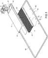
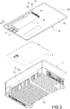
- an inverter device 10 mainly has a casing 1, one or a plurality of heat source elements 2, a heat dissipation structure 3 and one or a plurality of fans 4.
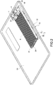
- the casing 1 has a base 11 and a cover 12, the base 11 is covered by the cover 12, an internal surface 121 and an external surface 122 are oppositely defined on the cover 12, and the internal surface 121 is arranged corresponding to the base 11.
- the base 11 has a bottom wall 111 and a lateral wall 112 surrounding the bottom wall 111.
- the internal surface 121 is arranged corresponding to the bottom wall 111.
- a plurality of aiding fins 113 is one piece extended from or bonded on an external side of the bottom wall 111, and the plurality of aiding fins 113 are used for dissipation heat accumulated in the bottom wall 111.
- a plurality of heat source elements 2 is provided, the respective heat source elements 2 are accommodated in the casing 1 and arranged on the bottom wall 111 of the base 11.
- the heat source elements 2 are electronic elements of the inverter device 10.
- the plurality of heat source elements 2 includes a circuit board 21, a plurality of capacitors 22, power semiconductor components 23 such as IGBTs or MOSFETs, relay(s) 24, common mode choke(s) 25 and inductor(s) 26.
- the circuit board 21 is fixed on the bottom wall 111, and the capacitors 22, the power semiconductor components 23 such as IGBTs or MOSFETs, the relay(s) 24 and the common mode choke(s) 25 are fixed on the circuit board 21.
- the inductor(s) 26 are arranged at one side of the circuit board 21 and fixed on the bottom wall 111, but scopes of the present disclosure should not be limited thereby, the inductor(s) 26 alternatively could be fixed on the circuit board 21. Heat generated by the aforementioned respective heat source elements 2 are transferred to the bottom wall 111 and further dissipated from the aiding fins 113.
- the power semiconductor components 23 such as IGBTs or MOSFETs are used as switches of a power conversion circuit such as DC/AC or DC/DC conversion circuits.
- the relay (Relay) 24 is used to disconnect external power input.
- the common mode choke 25 is a common mode inductor used to solve Electromagnetic Interference (EMI).
- EMI Electromagnetic Interference
- a plurality of supporting columns 27 fixed on the bottom wall 111 and arranged at one side of the circuit board 21 are accommodated in the casing 1, and the supporting column 27 is used for electrical connection, supporting the circuit board 21 or other circuit board(s).
- the number of the circuit board 21 is not limited to one according to aforementioned embodiment, a plurality of circuit boards 21 alternatively could be provided.
- the plurality of circuit boards 21 could be fixed on the bottom wall 111 and arranged in a plane or in a stack, and the plurality of capacitors 22, the power semiconductor components 23, and the relays 24, and the common mode chokes 25 are respectively fixed on the circuit boards 21.
- one part of the plurality of capacitors 22, the power semiconductor components 23, the relays 24 and the common mode chokes 25 could be arranged on the same circuit board, and another part of the plurality of capacitors 22, the power semiconductor components 23, the relays 24 and the common mode chokes 25 could be arranged on another circuit board(s).
- the inductor(s) 26 could be arranged at one side of the circuit board 21 or fixed on one of the circuit boards 21.
- the heat dissipation structure 3 is thermally contacted with the internal surface 121.
- the heat dissipation structure 3 shown in the present embodiment includes a plurality of heat dissipation fins 31 and a heat conductive plate 32.
- One surface of the heat conductive plate 32 is thermally contacted with the internal surface 121, and a plurality of heat dissipation fins 31 is connected to the other surface of the heat conductive plate 32.
- the plurality of heat dissipation fins 31 are arranged with each other and two vents 311 are thereby defined corresponding to two ends of the heat dissipation fins 31.
- scopes of the present disclosure should not be limited to the embodiment.
- the heat dissipation structure 3 could be a vapor chamber or include a vapor chamber, and the vapor chamber is thermally contacted with the internal surface 121.
- the heat dissipation structure 3 could be a heat pipe or include a heat sink and one or a plurality of heat pipes, and the heat sink is thermally contacted with the internal surface 121 and the heat pipes are inserted into the heat sink.
- the heat conductive plate 32 is fixed on the internal surface 121 by adhesive od screw according to the present embodiment, namely the heat conductive plate 32 and the cover 12 could be assembled in two separated parts.
- the heat conductive plate 32 and the cover 12 alternatively cloud be one piece formed.
- a fan 4 is accommodated in the casing 1 and arranged corresponding to one of the vents 311.
- the fan 4 could be arranged anywhere in the casing 1, but the fan 4 should be arranged corresponding to position of the heat dissipation structure 3 and airflow driven by the fan 4 should flow through heat dissipation structure 3.
- the fan 4 is used to accelerate airflow in the casing 1
- the heat dissipation structure 3 is used to absorb heat from the air in the casing 1 and transfer the heat to the external surface 122 of the cover 12.
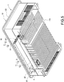
- the inverter device 10 further includes an air shroud 5.
- the air shroud 5 is fixed on the internal surface 121 and the plurality of heat dissipation fins 31 are covered thereby.
- Two openings 51 are defined on the air shroud 5 corresponding to the two vents 311, and an extension segment 52 arranged between one of the openings 51 and the plurality of heat dissipation fins 31 is defined on the air shroud 5.
- the fan 4 is arranged on the extension segment 52, and the fan 4 is therefore arranged corresponding to one of the openings 51.
- the heat dissipation structure 3 is thermally contacted with the internal surface 121 of the cover 12.
- the fan 4 is arranged corresponding to the heat dissipation structure 3, airflow in the casing 1 is accelerated by the fan 4 and driven to flow through the heat dissipation structure 3, and heat is absorbed from the airflow via the heat dissipation structure 3 and the heat is further transferred to the external surface 122 of the cover 12.
- heat could be more efficiently dissipated from the inverter device 10 through the cover 12 in relatively low temperature. Therefore, an efficiency of heat dissipation of the inverter device 10 is improved and the inverter device 10 is more durable.
- the inverter device 10 of the present disclosure further includes an air shroud 5 covering the plurality of heat dissipation fins 31.
- Two openings 51 are defined on the air shroud 5, the fan 4 is arranged corresponding to one of the openings 51, and the airflow driven by the fan 4 thereby could be guided to flow through the heat dissipation structure 3 and heat could be more efficiently transferred to the heat dissipation structure 3.
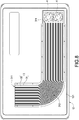
- the inverter device 10 is almost the same as the embodiments shown in Figs. 1 to 7 , the difference between the embodiment shown in Fig. 8 and the embodiment shown in Figs. 1 to 7 is that the plurality of heat dissipation fins 31 are bent to form one or a plurality of curved segments 312.
- the curved segments 312 are arranged on the cover 12 for turning extending direction, and an area for heat exchange of the plurality of heat dissipation fins 31 is thereby extended, and air flow channels are extended so that the heat is maintained in the heat dissipation structure 3 and further dissipated via the cover 12.
- the inverter device 10 is almost the same as the embodiment Figs. 1 to 7 , the difference between the embodiment shown in Fig. 9 and the embodiments shown in Figs. 1 to 7 is that a plurality of aiding fins 123 is one piece extended from or bonded on the external surface 122 of the cover 12, and heat could be dissipated from the cover 12 via the plurality of aiding fins 123.
- the heat dissipation structure 3 is thermally contacted with the internal surface 121 of the cover 12, and the aiding fins 123 are therefore not necessary to be disposed to cover the entire external surface 122. Namely, it is enough to efficiently dissipate heat from the cover 12 by disposing the aiding fins 123 to cover only one part of the external surface 122, and the heat is thereby prevented from being accumulated in the cover 12.
Landscapes
- Engineering & Computer Science (AREA)
- Microelectronics & Electronic Packaging (AREA)
- Physics & Mathematics (AREA)
- Thermal Sciences (AREA)
- Power Engineering (AREA)
- Inverter Devices (AREA)
- Cooling Or The Like Of Electrical Apparatus (AREA)
Applications Claiming Priority (1)
| Application Number | Priority Date | Filing Date | Title |
|---|---|---|---|
| CN201811533387.1A CN111327208B (zh) | 2018-12-14 | 2018-12-14 | 具散热机制的逆变器装置 |
Publications (3)
| Publication Number | Publication Date |
|---|---|
| EP3668292A1 true EP3668292A1 (fr) | 2020-06-17 |
| EP3668292C0 EP3668292C0 (fr) | 2025-03-05 |
| EP3668292B1 EP3668292B1 (fr) | 2025-03-05 |
Family
ID=67226001
Family Applications (1)
| Application Number | Title | Priority Date | Filing Date |
|---|---|---|---|
| EP19184862.1A Active EP3668292B1 (fr) | 2018-12-14 | 2019-07-08 | Dispositif inverseur ayant un mécanisme de dissipation de chaleur |
Country Status (5)
| Country | Link |
|---|---|
| US (1) | US10834857B2 (fr) |
| EP (1) | EP3668292B1 (fr) |
| JP (1) | JP6807988B2 (fr) |
| CN (1) | CN111327208B (fr) |
| ES (1) | ES3015982T3 (fr) |
Cited By (2)
| Publication number | Priority date | Publication date | Assignee | Title |
|---|---|---|---|---|
| CN111988967A (zh) * | 2020-08-31 | 2020-11-24 | 扬州冠中电力设备有限公司 | 一种光伏逆变器散热结构及其方法 |
| CN117477969A (zh) * | 2023-11-16 | 2024-01-30 | 华为数字能源技术有限公司 | 功率变换装置 |
Families Citing this family (17)
| Publication number | Priority date | Publication date | Assignee | Title |
|---|---|---|---|---|
| JP6872036B2 (ja) * | 2017-11-14 | 2021-05-19 | 株式会社Ihi | インバータ装置および電動コンプレッサ |
| KR102554431B1 (ko) * | 2018-09-05 | 2023-07-13 | 삼성전자주식회사 | 반도체 장치 및 반도체 장치 제조 방법 |
| EP3934401B1 (fr) * | 2020-06-30 | 2023-05-24 | Solaredge Technologies Ltd. | Mécanisme de refroidissement pour dispositif d'alimentation à compartiments multiples |
| CN112000151B (zh) | 2020-09-11 | 2022-01-28 | 山特电子(深圳)有限公司 | 用于滤波器电容组的温度保护装置 |
| EP4254782A4 (fr) * | 2020-12-22 | 2024-01-17 | Huawei Digital Power Technologies Co., Ltd. | Convertisseur de courant, échangeurs de chaleur, dissipateurs de chaleur et système de production d'énergie photovoltaïque |
| CN113163696A (zh) * | 2021-05-13 | 2021-07-23 | 黑龙江祥辉通信工程有限公司 | 一种基于5g的自动化散热通信装置 |
| CN113451073B (zh) * | 2021-05-27 | 2022-04-26 | 中汇瑞德电子(芜湖)有限公司 | 一种具有呼吸功能的散热型继电器 |
| CN113453510B (zh) * | 2021-06-28 | 2022-10-11 | 航天科技控股集团股份有限公司 | 一种逆变器的散热结构 |
| CN114289396A (zh) * | 2021-12-02 | 2022-04-08 | 东莞声索电子有限公司 | 工业超声波追频清洗机 |
| CN114793410B (zh) * | 2022-04-25 | 2023-11-24 | 太仓陶氏电气有限公司 | 一种逆变器大功率风冷水冷复合散热器 |
| CN115361833A (zh) * | 2022-06-09 | 2022-11-18 | 托付保(南京)电力技术有限公司 | 一种高频三电平dcdc直流变流器 |
| CN114977733A (zh) * | 2022-06-22 | 2022-08-30 | 华能吉林发电有限公司镇赉风电厂 | 一种风力发电变频器功率模块吸收电容散热装置 |
| CN114980709B (zh) * | 2022-07-28 | 2022-09-30 | 深圳市德兰明海科技有限公司 | 一种双风道散热组件以及应用该组件的逆变器 |
| KR20240106872A (ko) * | 2022-12-29 | 2024-07-08 | 엘지이노텍 주식회사 | 인버터 모듈 |
| CN118353285B (zh) * | 2024-04-22 | 2025-01-21 | 广东全芯半导体有限公司 | 一种逆变器电力系统及其制造方法 |
| WO2026031481A1 (fr) * | 2024-08-05 | 2026-02-12 | 深圳市华宝新能源股份有限公司 | Alimentation électrique de stockage d'énergie |
| CN120498236B (zh) * | 2025-07-16 | 2025-09-30 | 东莞市开关厂有限公司 | 一种智慧型双向逆变器 |
Citations (3)
| Publication number | Priority date | Publication date | Assignee | Title |
|---|---|---|---|---|
| US20060044762A1 (en) * | 2004-08-31 | 2006-03-02 | Mitsubishi Denki Kabushiki Kaisha | Vehicular power converter |
| US20080030951A1 (en) * | 2004-02-16 | 2008-02-07 | E2V Technologles (Uk) Limited | Electrical Apparatus and Cooling System |
| US20150116937A1 (en) * | 2013-10-24 | 2015-04-30 | Abb Oy | Electronic device with waterproof enclosure |
Family Cites Families (21)
| Publication number | Priority date | Publication date | Assignee | Title |
|---|---|---|---|---|
| KR920005988B1 (ko) * | 1988-08-31 | 1992-07-25 | 가부시기가이샤 히다찌세이사꾸쇼 | 인버터장치 |
| JPH1089820A (ja) | 1996-09-19 | 1998-04-10 | Ishikawajima Harima Heavy Ind Co Ltd | 発熱体収納用密封ケース |
| US5742478A (en) * | 1996-09-25 | 1998-04-21 | Wu; Chih-Hsien | Radiating structure of a power converter |
| WO2003060916A1 (fr) * | 2001-12-27 | 2003-07-24 | Fujitsu Limited | Dispositif a memoire et refroidisseur |
| US20030196779A1 (en) * | 2002-04-17 | 2003-10-23 | Sunonwealth Electric Machine Industry Co., Ltd | Heatsink device |
| CN1257442C (zh) * | 2003-04-14 | 2006-05-24 | 丽台科技股份有限公司 | 散热系统 |
| JP5407198B2 (ja) | 2008-07-02 | 2014-02-05 | 富士電機株式会社 | 電力変換装置のパワーモジュール |
| US20110203770A1 (en) * | 2008-10-27 | 2011-08-25 | Bae Systems Plc | Equipment case |
| CN201947153U (zh) | 2010-10-28 | 2011-08-24 | 伟肯(苏州)电气传动有限公司 | 模块化变频器 |
| JP5813582B2 (ja) * | 2012-06-01 | 2015-11-17 | 株式会社日本自動車部品総合研究所 | 電気機器 |
| CN104682457B (zh) * | 2013-11-26 | 2017-08-29 | 台达电子企业管理(上海)有限公司 | 电子装置及汽车的充电装置 |
| US9532485B2 (en) * | 2014-02-21 | 2016-12-27 | Lenovo (Beijing) Co., Ltd. | Heat dissipating device and electronic apparatus |
| JP2016021836A (ja) | 2014-07-15 | 2016-02-04 | 三菱電機株式会社 | パワーコンディショナ |
| CN104202954A (zh) * | 2014-09-28 | 2014-12-10 | 阳光电源股份有限公司 | 一种逆变器散热装置及逆变器 |
| CN107969163B (zh) | 2015-09-30 | 2020-03-06 | 日立汽车系统株式会社 | 电力变换装置 |
| JP2017158413A (ja) | 2016-03-04 | 2017-09-07 | 富士電機株式会社 | 密閉容器および電力変換装置 |
| CN107113997B (zh) * | 2016-09-26 | 2019-07-16 | 深圳市大疆创新科技有限公司 | 散热机构及具有该散热机构的无人飞行器 |
| CN206743092U (zh) * | 2017-03-30 | 2017-12-12 | 擎宏电子企业有限公司 | 高功率密度的直流转交直流功率转换器 |
| US10143117B2 (en) * | 2017-04-06 | 2018-11-27 | Chyng Hong Electronic Co., Ltd. | High power density DC-AC power inverter |
| CN208143032U (zh) * | 2018-03-23 | 2018-11-23 | 江苏苏美达五金工具有限公司 | 一种控制器、无刷电机及清洗机 |
| CN108983904A (zh) | 2018-07-05 | 2018-12-11 | 安徽百匠信息科技有限公司 | 一种防震散热性能好的计算机箱体 |
-
2018
- 2018-12-14 CN CN201811533387.1A patent/CN111327208B/zh active Active
-
2019
- 2019-07-03 US US16/503,068 patent/US10834857B2/en active Active
- 2019-07-04 JP JP2019125181A patent/JP6807988B2/ja active Active
- 2019-07-08 ES ES19184862T patent/ES3015982T3/es active Active
- 2019-07-08 EP EP19184862.1A patent/EP3668292B1/fr active Active
Patent Citations (3)
| Publication number | Priority date | Publication date | Assignee | Title |
|---|---|---|---|---|
| US20080030951A1 (en) * | 2004-02-16 | 2008-02-07 | E2V Technologles (Uk) Limited | Electrical Apparatus and Cooling System |
| US20060044762A1 (en) * | 2004-08-31 | 2006-03-02 | Mitsubishi Denki Kabushiki Kaisha | Vehicular power converter |
| US20150116937A1 (en) * | 2013-10-24 | 2015-04-30 | Abb Oy | Electronic device with waterproof enclosure |
Cited By (2)
| Publication number | Priority date | Publication date | Assignee | Title |
|---|---|---|---|---|
| CN111988967A (zh) * | 2020-08-31 | 2020-11-24 | 扬州冠中电力设备有限公司 | 一种光伏逆变器散热结构及其方法 |
| CN117477969A (zh) * | 2023-11-16 | 2024-01-30 | 华为数字能源技术有限公司 | 功率变换装置 |
Also Published As
| Publication number | Publication date |
|---|---|
| ES3015982T3 (en) | 2025-05-08 |
| US20200196491A1 (en) | 2020-06-18 |
| JP6807988B2 (ja) | 2021-01-06 |
| JP2020096507A (ja) | 2020-06-18 |
| EP3668292C0 (fr) | 2025-03-05 |
| CN111327208A (zh) | 2020-06-23 |
| CN111327208B (zh) | 2022-06-03 |
| US10834857B2 (en) | 2020-11-10 |
| EP3668292B1 (fr) | 2025-03-05 |
Similar Documents
| Publication | Publication Date | Title |
|---|---|---|
| US10834857B2 (en) | Inverter device having heat dissipation mechanism | |
| EP2879476B1 (fr) | Appareil électrique | |
| US8630090B2 (en) | Heat dissipation device for power conversion module | |
| CN115955825A (zh) | 一种逆变器、功率设备及光伏系统 | |
| EP3073812B1 (fr) | Module d'ensemble d'électronique de puissance intégré | |
| EP2658359B1 (fr) | Séparation thermique des ailettes de dissipateur thermique de châssis de commande électronique | |
| JP2000014169A (ja) | インバータ装置 | |
| CN101416373B (zh) | 电力变换装置 | |
| AU2015249128A1 (en) | Electrical device | |
| JP4093479B2 (ja) | 電源装置 | |
| US6930883B2 (en) | Heat-dispersing module of electronic device | |
| US10206310B2 (en) | Electronics assemblies incorporating three-dimensional heat flow structures | |
| WO2024198729A1 (fr) | Dispositif d'alimentation | |
| EP1429591A2 (fr) | Dispositifs de communication | |
| KR100619490B1 (ko) | 반도체 냉각 장치 | |
| CN107432100A (zh) | 用于开关柜空气调节的冷却设备 | |
| CN101416306A (zh) | 冷却器 | |
| CN101965117B (zh) | 散热装置 | |
| CN109690763B (zh) | 具有封闭壳体和冷却装置的开关柜 | |
| CN102083295A (zh) | 电子装置及其散热模组 | |
| WO2018173379A1 (fr) | Dispositif de conversion de courant | |
| TWI686128B (zh) | 具散熱機制的逆變器裝置 | |
| TWI692294B (zh) | 變頻器 | |
| US20180199467A1 (en) | Door cooler | |
| CN107113999A (zh) | 通风管散热结构及包括具有该通风管散热结构的通风管的电力转换装置 |
Legal Events
| Date | Code | Title | Description |
|---|---|---|---|
| PUAI | Public reference made under article 153(3) epc to a published international application that has entered the european phase |
Free format text: ORIGINAL CODE: 0009012 |
|
| STAA | Information on the status of an ep patent application or granted ep patent |
Free format text: STATUS: THE APPLICATION HAS BEEN PUBLISHED |
|
| AK | Designated contracting states |
Kind code of ref document: A1 Designated state(s): AL AT BE BG CH CY CZ DE DK EE ES FI FR GB GR HR HU IE IS IT LI LT LU LV MC MK MT NL NO PL PT RO RS SE SI SK SM TR |
|
| AX | Request for extension of the european patent |
Extension state: BA ME |
|
| STAA | Information on the status of an ep patent application or granted ep patent |
Free format text: STATUS: REQUEST FOR EXAMINATION WAS MADE |
|
| 17P | Request for examination filed |
Effective date: 20201217 |
|
| RBV | Designated contracting states (corrected) |
Designated state(s): AL AT BE BG CH CY CZ DE DK EE ES FI FR GB GR HR HU IE IS IT LI LT LU LV MC MK MT NL NO PL PT RO RS SE SI SK SM TR |
|
| STAA | Information on the status of an ep patent application or granted ep patent |
Free format text: STATUS: EXAMINATION IS IN PROGRESS |
|
| 17Q | First examination report despatched |
Effective date: 20221024 |
|
| GRAP | Despatch of communication of intention to grant a patent |
Free format text: ORIGINAL CODE: EPIDOSNIGR1 |
|
| STAA | Information on the status of an ep patent application or granted ep patent |
Free format text: STATUS: GRANT OF PATENT IS INTENDED |
|
| INTG | Intention to grant announced |
Effective date: 20240925 |
|
| GRAS | Grant fee paid |
Free format text: ORIGINAL CODE: EPIDOSNIGR3 |
|
| GRAA | (expected) grant |
Free format text: ORIGINAL CODE: 0009210 |
|
| STAA | Information on the status of an ep patent application or granted ep patent |
Free format text: STATUS: THE PATENT HAS BEEN GRANTED |
|
| AK | Designated contracting states |
Kind code of ref document: B1 Designated state(s): AL AT BE BG CH CY CZ DE DK EE ES FI FR GB GR HR HU IE IS IT LI LT LU LV MC MK MT NL NO PL PT RO RS SE SI SK SM TR |
|
| REG | Reference to a national code |
Ref country code: GB Ref legal event code: FG4D |
|
| REG | Reference to a national code |
Ref country code: CH Ref legal event code: EP |
|
| REG | Reference to a national code |
Ref country code: IE Ref legal event code: FG4D |
|
| REG | Reference to a national code |
Ref country code: DE Ref legal event code: R096 Ref document number: 602019066767 Country of ref document: DE |
|
| U01 | Request for unitary effect filed |
Effective date: 20250307 |
|
| U07 | Unitary effect registered |
Designated state(s): AT BE BG DE DK EE FI FR IT LT LU LV MT NL PT RO SE SI Effective date: 20250314 |
|
| REG | Reference to a national code |
Ref country code: ES Ref legal event code: FG2A Ref document number: 3015982 Country of ref document: ES Kind code of ref document: T3 Effective date: 20250508 |
|
| PG25 | Lapsed in a contracting state [announced via postgrant information from national office to epo] |
Ref country code: RS Free format text: LAPSE BECAUSE OF FAILURE TO SUBMIT A TRANSLATION OF THE DESCRIPTION OR TO PAY THE FEE WITHIN THE PRESCRIBED TIME-LIMIT Effective date: 20250605 |
|
| PGFP | Annual fee paid to national office [announced via postgrant information from national office to epo] |
Ref country code: GB Payment date: 20250515 Year of fee payment: 7 |
|
| PG25 | Lapsed in a contracting state [announced via postgrant information from national office to epo] |
Ref country code: NO Free format text: LAPSE BECAUSE OF FAILURE TO SUBMIT A TRANSLATION OF THE DESCRIPTION OR TO PAY THE FEE WITHIN THE PRESCRIBED TIME-LIMIT Effective date: 20250605 |
|
| PG25 | Lapsed in a contracting state [announced via postgrant information from national office to epo] |
Ref country code: HR Free format text: LAPSE BECAUSE OF FAILURE TO SUBMIT A TRANSLATION OF THE DESCRIPTION OR TO PAY THE FEE WITHIN THE PRESCRIBED TIME-LIMIT Effective date: 20250305 |
|
| U20 | Renewal fee for the european patent with unitary effect paid |
Year of fee payment: 7 Effective date: 20250606 |
|
| PG25 | Lapsed in a contracting state [announced via postgrant information from national office to epo] |
Ref country code: GR Free format text: LAPSE BECAUSE OF FAILURE TO SUBMIT A TRANSLATION OF THE DESCRIPTION OR TO PAY THE FEE WITHIN THE PRESCRIBED TIME-LIMIT Effective date: 20250606 |
|
| PG25 | Lapsed in a contracting state [announced via postgrant information from national office to epo] |
Ref country code: SM Free format text: LAPSE BECAUSE OF FAILURE TO SUBMIT A TRANSLATION OF THE DESCRIPTION OR TO PAY THE FEE WITHIN THE PRESCRIBED TIME-LIMIT Effective date: 20250305 |
|
| PGFP | Annual fee paid to national office [announced via postgrant information from national office to epo] |
Ref country code: ES Payment date: 20250806 Year of fee payment: 7 |
|
| PG25 | Lapsed in a contracting state [announced via postgrant information from national office to epo] |
Ref country code: PL Free format text: LAPSE BECAUSE OF FAILURE TO SUBMIT A TRANSLATION OF THE DESCRIPTION OR TO PAY THE FEE WITHIN THE PRESCRIBED TIME-LIMIT Effective date: 20250305 |
|
| PG25 | Lapsed in a contracting state [announced via postgrant information from national office to epo] |
Ref country code: CZ Free format text: LAPSE BECAUSE OF FAILURE TO SUBMIT A TRANSLATION OF THE DESCRIPTION OR TO PAY THE FEE WITHIN THE PRESCRIBED TIME-LIMIT Effective date: 20250305 |
|
| PG25 | Lapsed in a contracting state [announced via postgrant information from national office to epo] |
Ref country code: SK Free format text: LAPSE BECAUSE OF FAILURE TO SUBMIT A TRANSLATION OF THE DESCRIPTION OR TO PAY THE FEE WITHIN THE PRESCRIBED TIME-LIMIT Effective date: 20250305 |
|
| PG25 | Lapsed in a contracting state [announced via postgrant information from national office to epo] |
Ref country code: IS Free format text: LAPSE BECAUSE OF FAILURE TO SUBMIT A TRANSLATION OF THE DESCRIPTION OR TO PAY THE FEE WITHIN THE PRESCRIBED TIME-LIMIT Effective date: 20250705 |
|
| PLBE | No opposition filed within time limit |
Free format text: ORIGINAL CODE: 0009261 |
|
| STAA | Information on the status of an ep patent application or granted ep patent |
Free format text: STATUS: NO OPPOSITION FILED WITHIN TIME LIMIT |
|
| REG | Reference to a national code |
Ref country code: CH Ref legal event code: L10 Free format text: ST27 STATUS EVENT CODE: U-0-0-L10-L00 (AS PROVIDED BY THE NATIONAL OFFICE) Effective date: 20260114 |
|
| 26N | No opposition filed |
Effective date: 20251208 |
|
| REG | Reference to a national code |
Ref country code: CH Ref legal event code: H13 Free format text: ST27 STATUS EVENT CODE: U-0-0-H10-H13 (AS PROVIDED BY THE NATIONAL OFFICE) Effective date: 20260224 |
|
| PG25 | Lapsed in a contracting state [announced via postgrant information from national office to epo] |
Ref country code: CH Free format text: LAPSE BECAUSE OF NON-PAYMENT OF DUE FEES Effective date: 20250731 |