EP3669951A1 - Élément ouverture pour produit fusible électriquement déclenchable d'un élément conducteur de fluide d'extinction - Google Patents
Élément ouverture pour produit fusible électriquement déclenchable d'un élément conducteur de fluide d'extinction Download PDFInfo
- Publication number
- EP3669951A1 EP3669951A1 EP19209634.5A EP19209634A EP3669951A1 EP 3669951 A1 EP3669951 A1 EP 3669951A1 EP 19209634 A EP19209634 A EP 19209634A EP 3669951 A1 EP3669951 A1 EP 3669951A1
- Authority
- EP
- European Patent Office
- Prior art keywords
- solder
- conducting element
- sprinkler
- extinguishing fluid
- extinguishing
- Prior art date
- Legal status (The legal status is an assumption and is not a legal conclusion. Google has not performed a legal analysis and makes no representation as to the accuracy of the status listed.)
- Withdrawn
Links
- 229910000679 solder Inorganic materials 0.000 title claims description 37
- 239000012530 fluid Substances 0.000 title claims description 19
- 230000001960 triggered effect Effects 0.000 title description 9
- XLYOFNOQVPJJNP-UHFFFAOYSA-N water Substances O XLYOFNOQVPJJNP-UHFFFAOYSA-N 0.000 claims abstract description 6
- 238000012360 testing method Methods 0.000 claims description 25
- 238000005476 soldering Methods 0.000 claims description 9
- 238000002844 melting Methods 0.000 claims description 8
- 230000008018 melting Effects 0.000 claims description 8
- 239000000155 melt Substances 0.000 claims description 7
- 230000032683 aging Effects 0.000 claims description 5
- 238000000034 method Methods 0.000 claims description 3
- 239000011521 glass Substances 0.000 description 15
- 238000010438 heat treatment Methods 0.000 description 14
- 230000007246 mechanism Effects 0.000 description 12
- 239000003795 chemical substances by application Substances 0.000 description 11
- 239000002184 metal Substances 0.000 description 9
- 229910052751 metal Inorganic materials 0.000 description 9
- 239000000463 material Substances 0.000 description 8
- 239000003708 ampul Substances 0.000 description 5
- 241000221931 Hypomyces rosellus Species 0.000 description 4
- 230000005855 radiation Effects 0.000 description 4
- 229910001369 Brass Inorganic materials 0.000 description 3
- 239000010951 brass Substances 0.000 description 3
- 239000000428 dust Substances 0.000 description 3
- 239000000779 smoke Substances 0.000 description 3
- 239000004809 Teflon Substances 0.000 description 2
- 229920006362 Teflon® Polymers 0.000 description 2
- ZMDCATBGKUUZHF-UHFFFAOYSA-N beryllium nickel Chemical group [Be].[Ni] ZMDCATBGKUUZHF-UHFFFAOYSA-N 0.000 description 2
- 238000013461 design Methods 0.000 description 2
- 238000011161 development Methods 0.000 description 2
- 230000018109 developmental process Effects 0.000 description 2
- 239000012799 electrically-conductive coating Substances 0.000 description 2
- 239000007788 liquid Substances 0.000 description 2
- 238000007789 sealing Methods 0.000 description 2
- 239000010935 stainless steel Substances 0.000 description 2
- 229910001220 stainless steel Inorganic materials 0.000 description 2
- 239000004753 textile Substances 0.000 description 2
- 229910000952 Be alloy Inorganic materials 0.000 description 1
- 229910000906 Bronze Inorganic materials 0.000 description 1
- RYGMFSIKBFXOCR-UHFFFAOYSA-N Copper Chemical compound [Cu] RYGMFSIKBFXOCR-UHFFFAOYSA-N 0.000 description 1
- 229910000990 Ni alloy Inorganic materials 0.000 description 1
- OAICVXFJPJFONN-UHFFFAOYSA-N Phosphorus Chemical compound [P] OAICVXFJPJFONN-UHFFFAOYSA-N 0.000 description 1
- 230000004913 activation Effects 0.000 description 1
- 238000004026 adhesive bonding Methods 0.000 description 1
- 230000008901 benefit Effects 0.000 description 1
- 230000015572 biosynthetic process Effects 0.000 description 1
- 239000010974 bronze Substances 0.000 description 1
- 239000004020 conductor Substances 0.000 description 1
- 229910052802 copper Inorganic materials 0.000 description 1
- 239000010949 copper Substances 0.000 description 1
- KUNSUQLRTQLHQQ-UHFFFAOYSA-N copper tin Chemical compound [Cu].[Sn] KUNSUQLRTQLHQQ-UHFFFAOYSA-N 0.000 description 1
- 230000003247 decreasing effect Effects 0.000 description 1
- 230000000694 effects Effects 0.000 description 1
- 238000010292 electrical insulation Methods 0.000 description 1
- 210000003746 feather Anatomy 0.000 description 1
- 239000000835 fiber Substances 0.000 description 1
- 238000009434 installation Methods 0.000 description 1
- 238000012423 maintenance Methods 0.000 description 1
- 238000007726 management method Methods 0.000 description 1
- 238000004519 manufacturing process Methods 0.000 description 1
- 239000012811 non-conductive material Substances 0.000 description 1
- 230000003647 oxidation Effects 0.000 description 1
- 238000007254 oxidation reaction Methods 0.000 description 1
- 239000004033 plastic Substances 0.000 description 1
- 229920001343 polytetrafluoroethylene Polymers 0.000 description 1
- 238000007493 shaping process Methods 0.000 description 1
- 239000007787 solid Substances 0.000 description 1
- 239000007921 spray Substances 0.000 description 1
- 238000003892 spreading Methods 0.000 description 1
- 230000007480 spreading Effects 0.000 description 1
- 238000009941 weaving Methods 0.000 description 1
- 238000003466 welding Methods 0.000 description 1
- 238000009736 wetting Methods 0.000 description 1
- 238000013316 zoning Methods 0.000 description 1
Images



Classifications
-
- A—HUMAN NECESSITIES
- A62—LIFE-SAVING; FIRE-FIGHTING
- A62C—FIRE-FIGHTING
- A62C37/00—Control of fire-fighting equipment
- A62C37/08—Control of fire-fighting equipment comprising an outlet device containing a sensor, or itself being the sensor, i.e. self-contained sprinklers
- A62C37/10—Releasing means, e.g. electrically released
- A62C37/11—Releasing means, e.g. electrically released heat-sensitive
- A62C37/12—Releasing means, e.g. electrically released heat-sensitive with fusible links
-
- H—ELECTRICITY
- H01—ELECTRIC ELEMENTS
- H01H—ELECTRIC SWITCHES; RELAYS; SELECTORS; EMERGENCY PROTECTIVE DEVICES
- H01H85/00—Protective devices in which the current flows through a part of fusible material and this current is interrupted by displacement of the fusible material when this current becomes excessive
- H01H85/02—Details
- H01H85/22—Intermediate or auxiliary parts for carrying, holding, or retaining fuse, co-operating with base or fixed holder, and removable therefrom for renewing the fuse
-
- A—HUMAN NECESSITIES
- A62—LIFE-SAVING; FIRE-FIGHTING
- A62C—FIRE-FIGHTING
- A62C37/00—Control of fire-fighting equipment
- A62C37/04—Control of fire-fighting equipment with electrically-controlled release
-
- A—HUMAN NECESSITIES
- A62—LIFE-SAVING; FIRE-FIGHTING
- A62C—FIRE-FIGHTING
- A62C37/00—Control of fire-fighting equipment
- A62C37/08—Control of fire-fighting equipment comprising an outlet device containing a sensor, or itself being the sensor, i.e. self-contained sprinklers
- A62C37/10—Releasing means, e.g. electrically released
- A62C37/11—Releasing means, e.g. electrically released heat-sensitive
- A62C37/14—Releasing means, e.g. electrically released heat-sensitive with frangible vessels
-
- A—HUMAN NECESSITIES
- A62—LIFE-SAVING; FIRE-FIGHTING
- A62C—FIRE-FIGHTING
- A62C37/00—Control of fire-fighting equipment
- A62C37/36—Control of fire-fighting equipment an actuating signal being generated by a sensor separate from an outlet device
- A62C37/38—Control of fire-fighting equipment an actuating signal being generated by a sensor separate from an outlet device by both sensor and actuator, e.g. valve, being in the danger zone
- A62C37/40—Control of fire-fighting equipment an actuating signal being generated by a sensor separate from an outlet device by both sensor and actuator, e.g. valve, being in the danger zone with electric connection between sensor and actuator
-
- A—HUMAN NECESSITIES
- A62—LIFE-SAVING; FIRE-FIGHTING
- A62C—FIRE-FIGHTING
- A62C37/00—Control of fire-fighting equipment
- A62C37/50—Testing or indicating devices for determining the state of readiness of the equipment
-
- H—ELECTRICITY
- H01—ELECTRIC ELEMENTS
- H01H—ELECTRIC SWITCHES; RELAYS; SELECTORS; EMERGENCY PROTECTIVE DEVICES
- H01H89/00—Combinations of two or more different basic types of electric switches, relays, selectors and emergency protective devices, not covered by any single one of the other main groups of this subclass
Definitions
- thermo bulbs are standard in the sprinkler industry.
- a closed glass ampoule with at least one medium e.g. B filled with gas or at least two media (liquid and glass bubble).
- gas and / or liquid expands and a pressure is built up inside the glass ampoule until a threshold value is reached at which the glass ampoule bursts / bursts and thus releases the sprinkler function and the fluid extinguishing agent flow.
- the glass ampoule itself is also mechanically biased, i.e. H. it presses on a closure that is exposed to the water pressure in the pipeline on the overlying side.
- fusible link sprinklers in which the fusible link is under mechanical prestressing, so that when the temperature in the outer vicinity of the fusible link, e.g. B. due to an existing fire or another thermal Event is heated, the solder at a defined temperature softens, melts, or the like and thus yields the solder due to the mechanical bias and releases the sprinkler function and the fluid extinguishing agent flow.
- the sprinkler function i. H. Firefighting with the sprinkler is already released before an actual fire event takes on larger proportions and before the thermal energy of the fire event triggers the known sprinkler.
- the fire spreads quickly it can also make sense to use sprinklers to trigger the actual fire, e.g. carry out a pre-wetting.
- This prior art discloses a sprinkler with a glass bulb (thermo bulb principle) and on the outside of the bulb an electrically conductive coating, which forms an electrical resistance (R), is applied, which, if necessary, by closing a switch and applying a voltage can be flowed through by a current.
- the glass bulb and thus the medium of the glass bulb are heated until a thermal limit is reached, at which point the glass bulb bursts, thus releasing the sprinkler function.
- the object of the present invention is to provide a solution for a soldering solder opening element for extinguishing fluid-conducting elements for a fire-fighting system, which enables greater reliability and functional reliability than the known solutions.
- An extinguishing fluid-conducting element is, according to the understanding of the present application, for. B. a fusible link sprinkler or a control valve with fusible link opening element or another device in which the flow of the extinguishing fluid is made possible by triggering the fusible link opening element by means of a fusible link opening element.
- the present application and invention also include a fire-fighting system with an extinguishing-fluid-conducting element, as well as a method for testing an extinguishing-fluid-conducting element.
- the invention is based on the knowledge that the fusible link opening element regularly consists of electrically conductive parts and that by integrating the fusible link opening element in an electrical circuit, it is possible that not only the conducting parts of the fusible link opening element are flowed through by the current, but that the fusible link is doing so heated to a predetermined temperature, so that the fusible link opening element is opened and the extinguishing fluid-conducting element is thus triggered.
- thermocouple for. B. a heating resistor, in contact with the fusible link or in close proximity to this.
- the heating resistor can also be designed such that it virtually dissolves itself, such as a classic fuse.
- the triggering of the switch does not necessarily have to assume a fire, but can also take place if another parameter in the space on the area where the extinguishing fluid-conducting element is arranged exceeds a predetermined value. If, for example, the room is equipped with a smoke detector, the switch can be closed if a predetermined smoke value is exceeded. In the event that a radiation sensor is installed, the switch is closed when a certain radiation value is exceeded. If a certain heat sensor is installed in the room, the switch closes when a certain room temperature is exceeded. In one of the aforementioned cases, a corresponding sensor, e.g. B. smoke, radiation, heat, temperature sensor, etc. a control function and causes the switch to close when a predetermined value, which is determined by the respective sensors, is exceeded.
- a corresponding sensor e.g. B. smoke, radiation, heat, temperature sensor, etc. a control function and causes the switch to close when a predetermined value, which is determined by the respective sensors, is exceeded.
- the heating element is preferably electrically insulated from the outside, so that in the event that cobwebs, dust, textiles or other weaving materials should have deposited on the heating element, they cannot impair the electrical current flow.
- thermocouple Even after many years or decades where the sprinkler function has not been triggered, cobwebs, dusts, textile fibers etc. that are regularly in the air and also deposit on the fusible link cannot impair the electrical heating function of the thermocouple.
- the electrically heatable heating element z. B. heating resistor R is connected to a voltage source and an open switch S, by closing the switch S current I flows from the voltage source through the resistor R and then generates thermal energy there according to the formula "I 2 R".
- Switch S can already be closed when a fire has occurred but the temperature at the sprinkler is not yet high enough to trigger the sprinkler.
- the voltage source can be a battery, but can also be the normal electrical supply network and it is possible that a switch z. B. in the fire alarm and / or extinguishing control center, a large number or a defined number of sprinklers for triggering.
- Figure 1 shows in the two representations in Figure 1a and Figure 1b the cross section ( Figure 1a ) and the view ( Figure 1b ) of a known fusible link sprinkler with a fusible link trigger element.
- Such a sprinkler 1 has a deflector 2, which is penetrated centrally by a screw 3.
- the trigger mechanism 4 of the fusible link release element can be adjusted, which consists, for example, of a rod 5, a curved lever 6 mounted between the screw 3 and the rod 5, and two plates connected by a fusible link.
- the straight lever 5 has a foot end 10, which lies on a base 11, which in turn is received by a receptacle 12 (a so-called pip cap). Furthermore, each lever has a head end 25, which lies in a recess 26 of the lever 6.
- This receptacle 12 has a circumferential shoulder 13 which on a spring 16 z.
- the sprinkler body 14 has a thread 15 in the lower area, which can be screwed into a pipe through which water or other fluid extinguishing agent is brought to the sprinkler and since the sprinkler body 14 is hollow on the inside, the fluid extinguishing agent (Flm) presses against the receptacle 12 and the spring 16 from the inside.
- the spring 16 is coated with Teflon in order to develop the highest possible sealing effect, because as long as the sprinkler release mechanism 4 is still in the sprinkler 1, a sufficient force must be opposed to the pressure of the fluid extinguishing agent (Flm) and at the same time the fluid extinguishing agent must not come out of the Escape inside the sprinkler body 14.
- Figure 1b shows the side view of the in Figure 1a Sprinklers shown.
- the sprinkler body 14 has an O-shaped frame 16 which supports the deflector 2.
- the frame 17 is part of the sprinkler body 14 and as can be seen, the screw 3 passes through the frame 16 where the deflector is also held by the frame.
- connection between the rod 5 and the lever 6 is arranged slightly offset from the ventral axis Z.
- a force is thus also exerted on the lever 6, the outer region of which would like to move away from the rod 5.
- the fusible link can be designed so that it melts at a desired temperature, and if this is the case, the plates 8 and 9 separate from one another, ie the front part 7 of the lever 6 moves outwards (in Figure 1a to the right towards 24) and the entire trigger mechanism falls out of its as in Figure 1 Locking shown with the result that no pressure from the outside opposes the internal pressure of the fluid extinguishing agent and this therefore flows from the inside of the sprinkler body 14 and preferably sprayed onto the deflector 2, which ensures that a desired spray plate is set.
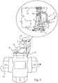
- Figure 2 shows an inventive development of the known sprinkler.
- the sprinkler body 14 is regularly made of metal, e.g. B. brass, the deflector is also made of metal, for. B. phosphor bronze, the base 11 is also made of metal, for. B. brass, the screw 3 is also made of metal, for. B. stainless steel and the lever 5 and 6 are also made of metal, e.g. B. stainless steel.
- the two fusible plates 8 and 9 are also made of metal, for. B. a nickel-beryllium alloy and the receptacle 12 is also made of metal, for. B. brass or copper.
- the spring 16 is also made of metal, but is z. B. coated with polytetrafluoroethylene (Teflon). This means that the receptacle 12 lying on the spring 16 is electrically non-conductively connected to the sprinkler body 14.
- the frame of the sprinkler body 14 is at least but the screw 13 is connected via an electrical line to the pole of a voltage source.
- a further line connects in the foot region 10 of the lever 5 to the other pole of the voltage source 27.
- the electrical line is produced between the foot region of the lever 5 and the voltage source 27 via the electrically conductive base 11, which is electrically conductively connected to the receptacle 12 to which the first electrical line 18 is clamped.
- the second electrical line 19 can, however, also be attached or connected to the frame of the sprinkler 14 directly on the screw 3 or the head end 25 of the trigger mechanism 4 or another part of the sprinkler body (e.g. screwed, soldered, etc.). ).
- this spring 16 electrically isolates the receptacle 12 from the frame of the sprinkler 14.
- the levers 5 and / or 6 and / or the plates 8 and 9 and possibly also the fusible link 17 which connects the plates heat up instantaneously, so that the triggering mechanism is triggered and released almost immediately , because the solder can be melted very quickly with the flow of the current.
- a current I flows from the voltage source or current source (voltage source can be a DC voltage or an AC voltage current).
- voltage source can be a DC voltage or an AC voltage current.
- the current also flows through the levers 5 and 6. or the plates 8 and 9 and the solder 23 located between them.
- the solder material is preferably one which has a specific electrical resistance.
- Typical material for the fusible link is beryllium nickel UNS-N03360.
- Such a beryllium nickel alloy has a specific electrical resistance of 28.7 to 43 ⁇ cm.
- Another solder material with an even greater specific electrical resistance is also suitable according to the invention and then leads to an even faster melt, so that an even faster triggering is possible.
- FIG 3 shows the application of the invention also for a control valve with an input line 20 and two output lines 21, 22. These lines are designed for the fluid extinguishing agent flow.
- the trigger mechanism 4 is again formed between two pressure points.
- valve tappet 31 closes the flow of a fluid extinguishing agent with its rear part, which is not visible in the figure, and its pressure is applied to the lower connection of the control valve.
- trigger mechanism by closing an electrical switch S as with the same or similar functionality as in Figure 2 described, triggers, is moved by the fluid pressure of the valve tappet and thus releases the flow of the fluid extinguishing agent through the two outlets 21 and 22.
- a heating wire resistor may be connected to or arranged close to the fusible link and if a current then flows through the heating wire resistor, the resistance heats up and thus causes the fusible link to melt.
- the fusible link or the two plates 8 and 9, which are connected by means of the fusible link are made from a material which has very good heating wire resistance properties, that is to say a high specific resistance, so that when these parts flow through, with As much heat as possible is generated which quickly melts the solder.
- the thermal heating element can be constructed as a heating resistor or in the manner of a fuse (such fuses are state of the art), which means that when the fuse flows through it is not only sufficient Heat for melting the fusible link is generated, but the fuse also destroys itself (tears open).
- the fuse is designed so that a predetermined current can flow through it for a predetermined period of time, and this is designed such that enough heat is generated on the one hand for reliable melting of the solder, but on the other hand also for melting the fuse.
- solder itself is electrically conductive and / or magnetic and is surrounded by a coil which, when a current flows through the coil, applies a force to the solder, which tears it, or which in turn melts the solder heated to such an extent that it melts almost instantaneously and thus releases the sprinkler or valve function.
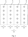
- FIG 4 the elevation of an area is shown, which is divided into 4 sectors a, b, c, d.
- Each sector is assigned a corresponding switch S1, S2, S3, S4, so that, if necessary, the corresponding sprinklers of a sector can also be activated by closing the corresponding switch, that is to say that with a single switch command, e.g. B. with the closure of switch S1, the sprinklers of sector a begin almost simultaneously to bring water to the area of sector a.
- the switches can be located in the fire alarm and / or extinguishing control center (BMZ), but can also be spatially assigned to the individual sectors so that they can be triggered by the appropriate personnel if a fire develops.
- BMZ fire alarm and / or extinguishing control center
- the switches can be located in the fire alarm and / or extinguishing control center (BMZ), but can also be spatially assigned to the individual sectors so that they can be triggered by the appropriate personnel if a fire develops.
- the individual assignment of switches to the sprinklers is also conceivable.
- the voltage / current-carrying cables to the sprinkler can be attached to the sprinkler or its supply parts (such as sprinkler pipes) either detachably (e.g. by screwing) or non-detachably (e.g. welding, soldering, gluing), as is one Clamp bracket possible. It is important that there is an electrically conductive contact between the current / voltage-carrying cables and the connected components of the sprinkler are guaranteed at all times, so that when the switch is closed, the current mentioned can flow in order to melt the solder and thus trigger the sprinkler.
- the invention also includes the possibility that the electrical conductivity is tested in a test mode by (for a short time) a small test current flowing through the line and by measuring the existence of the electrical contacts and the conductivity of the current by the defined current part becomes. The resulting current is measurable, but it is not sufficient to melt the solder.
- Such a check can also be routinely carried out at recurring intervals, e.g. B. once a week, once a year, etc., and the test result can be logged, saved and / or displayed on a corresponding display of the fire alarm and / or extinguishing control center (BMZ).
- recurring intervals e.g. B. once a week, once a year, etc.
- a test cycle is designed so that a current flows through the current-carrying parts which is significantly lower than current by means of which the soldering sprinkler can be triggered electrically.
- test current is a current of the order of 10%, that is 1 A or less, e.g. B. 1 mA. It is crucial that the test current can still be measured safely in the test cycle.
- the test cycle according to the invention also has the advantage that damage to the sprinkler can be determined under certain circumstances.
- An aging of the components of the sprinkler can also be determined with this, namely when the components of the sprinkler through which the current flows assume an increased or decreased resistance due to their aging, which can also happen due to material setting, material oxidation and other aging influences.
- Figure 5 shows a cross section through an alternative arrangement or design of a solder sprinkler.
- the reference numerals relate to the parts that are also in Figure 2 are described.
- the rod 5 is arranged slightly inclined from the central axis Z, so that the screw acts on the front part of the lever 6, so that tightening the screw of the lever with its plate 8 tries to move away from the rod or its plate 9 to move.
- the fusible link 23 located between the plates 8 and 9, as long as it is still in a solid state and as long as this fusible link is not yet heated to its predefined release temperature. If this is done by closing the switch S, a current I then flows through the electrical circuit, in which the fusible link opening element is integrated.
- Figure 6 shows a perspective view of the solder sprinkler according to Figure 5 .
- the technical function control can also be carried out with the devices for electrically triggering the solder sprinkler when the electrically conductive parts are only subjected to a low test current, as mentioned, but without solving the sprinkler cause.
- the configuration and structure of the extinguishing fluid-conducting element according to the invention also enables a method for testing the extinguishing-fluid-conducting element to be carried out, a test cycle being provided in which a test current flows through the electrical circuit, the test current being significantly lower, i. H. e.g. B. is less than 10%, 5% or less than the current for triggering the fusible link opening element and wherein in the test cycle the contacts and / or aging or by functionality of the extinguishing fluid-conducting element or the fusible link opening element are checked, it is determined, for example, in the test cycle that the Test current does not flow through the electrical circuit, it can be assumed that there is a clock interruption, e.g. B. there is a line break so that in such a case a targeted error check or maintenance can take place.
- a clock interruption e.g. B. there is a line break
Landscapes
- Health & Medical Sciences (AREA)
- Public Health (AREA)
- Business, Economics & Management (AREA)
- Emergency Management (AREA)
- Fire-Extinguishing By Fire Departments, And Fire-Extinguishing Equipment And Control Thereof (AREA)
Applications Claiming Priority (1)
| Application Number | Priority Date | Filing Date | Title |
|---|---|---|---|
| DE102018132859.1A DE102018132859A1 (de) | 2018-12-19 | 2018-12-19 | Elektrisch auslösbares Schmelzlotöffnungselement eines löschfluidleitenden Elementes |
Publications (1)
| Publication Number | Publication Date |
|---|---|
| EP3669951A1 true EP3669951A1 (fr) | 2020-06-24 |
Family
ID=68609916
Family Applications (1)
| Application Number | Title | Priority Date | Filing Date |
|---|---|---|---|
| EP19209634.5A Withdrawn EP3669951A1 (fr) | 2018-12-19 | 2019-11-18 | Élément ouverture pour produit fusible électriquement déclenchable d'un élément conducteur de fluide d'extinction |
Country Status (3)
| Country | Link |
|---|---|
| US (1) | US20200203111A1 (fr) |
| EP (1) | EP3669951A1 (fr) |
| DE (1) | DE102018132859A1 (fr) |
Families Citing this family (2)
| Publication number | Priority date | Publication date | Assignee | Title |
|---|---|---|---|---|
| EP3753607B1 (fr) * | 2019-06-17 | 2025-02-26 | Marioff Corporation OY | Ampoule d'arroseur |
| CN118251259A (zh) * | 2021-10-01 | 2024-06-25 | 霍顿集团有限公司 | 用于厨房通风的火灾检测和报警系统、装置和方法 |
Citations (6)
| Publication number | Priority date | Publication date | Assignee | Title |
|---|---|---|---|---|
| US2272857A (en) * | 1940-09-27 | 1942-02-10 | Peter G Vonich | Fusible link |
| DE1272131B (de) * | 1958-07-24 | 1968-07-04 | Walther & Cie Ag | Selbsttaetige Feuerloeschanlage |
| US4623023A (en) | 1980-07-18 | 1986-11-18 | The Viking Corporation | Sprinkler head |
| WO2015191619A1 (fr) * | 2014-06-09 | 2015-12-17 | Tyco Fire Products Lp | Système commandé et procédés pour la protection de marchandises contre l'incendie |
| US20170120090A1 (en) | 2014-06-09 | 2017-05-04 | Tyco Fire Products Lp | Controlled system and methods for storage fire protection |
| WO2017105289A1 (fr) | 2015-11-18 | 2017-06-22 | Общество С Ограниченной Ответственностью "Форносовское Научно-Производственное Предприятие "Гефест" | Sprinkler à contrôle de fonctionnement |
-
2018
- 2018-12-19 DE DE102018132859.1A patent/DE102018132859A1/de not_active Withdrawn
-
2019
- 2019-11-18 EP EP19209634.5A patent/EP3669951A1/fr not_active Withdrawn
- 2019-12-04 US US16/703,441 patent/US20200203111A1/en not_active Abandoned
Patent Citations (6)
| Publication number | Priority date | Publication date | Assignee | Title |
|---|---|---|---|---|
| US2272857A (en) * | 1940-09-27 | 1942-02-10 | Peter G Vonich | Fusible link |
| DE1272131B (de) * | 1958-07-24 | 1968-07-04 | Walther & Cie Ag | Selbsttaetige Feuerloeschanlage |
| US4623023A (en) | 1980-07-18 | 1986-11-18 | The Viking Corporation | Sprinkler head |
| WO2015191619A1 (fr) * | 2014-06-09 | 2015-12-17 | Tyco Fire Products Lp | Système commandé et procédés pour la protection de marchandises contre l'incendie |
| US20170120090A1 (en) | 2014-06-09 | 2017-05-04 | Tyco Fire Products Lp | Controlled system and methods for storage fire protection |
| WO2017105289A1 (fr) | 2015-11-18 | 2017-06-22 | Общество С Ограниченной Ответственностью "Форносовское Научно-Производственное Предприятие "Гефест" | Sprinkler à contrôle de fonctionnement |
Also Published As
| Publication number | Publication date |
|---|---|
| US20200203111A1 (en) | 2020-06-25 |
| DE102018132859A1 (de) | 2020-06-25 |
Similar Documents
| Publication | Publication Date | Title |
|---|---|---|
| DE69323904T2 (de) | Schnellreagierender sprinklerkopf | |
| EP3459601B1 (fr) | Tête de gicleur | |
| DE69019114T2 (de) | Verfahren und Verbindungsteil mit einem elektrischen Widerstand zum Verschweissen von Elementen aus thermoplastischem Material. | |
| EP2286879B1 (fr) | Arroseur sprinkler à déclenchement commandé | |
| EP3134187B1 (fr) | Dispositif d'extinction d'incendie et/ou de protection contre les incendies miniature et compact | |
| EP2038018B1 (fr) | Fermeture pour gicleur d'incendie et buses avec déclenchement thermique | |
| DE102007014334A1 (de) | Schmelzlegierungselement, Thermosicherung mit einem Schmelzlegierungselement sowie Verfahren zum Herstellen einer Thermosicherung | |
| CH616269A5 (fr) | ||
| EP3669951A1 (fr) | Élément ouverture pour produit fusible électriquement déclenchable d'un élément conducteur de fluide d'extinction | |
| WO2011054523A1 (fr) | Appareil électrique | |
| DE10056778A1 (de) | Brandschutzanlage mit Glasfasssensoren | |
| DE1566704A1 (de) | Hitzeempfindliches Kabel fuer ein Feueranzeige- und Verhuetungsmittel | |
| EP0138195A2 (fr) | Appareil extincteur | |
| AT404980B (de) | Absperrvorrichtung für eine gasversorgungsleitung | |
| DE895576C (de) | Thermokontakt oder Sicherung fuer automatische Feueralarmanlagen | |
| CH182194A (de) | Ubertemperaturschutzvorrichtung für elektrisch beheizte Wärmeanlagen, insbesondere für durch Thermostaten gesteuerte Wärmeanlagen. | |
| DE3506152C2 (fr) | ||
| WO2006074648A1 (fr) | Buse de pulverisation et buse a effet giratoire pour installations de lutte contre l'incendie et dispositif de declenchement associe actionnable en fonction de la temperature | |
| EP1172779A2 (fr) | Tuyaux avec détection d'incendie intégrée | |
| CH633746A5 (de) | Verfahren und vorrichtung zum verbinden von rohrleitungselementen aus schweissbarem kunststoff. | |
| DE202013003505U1 (de) | Thermosensitiver und/oder drucksensitiver Schalter mit Auslöseeinrichtung | |
| DE497129C (de) | Anzeigevorrichtung fuer eine UEberspannungssicherung, die in einem vollkommen geschlossenen Gehaeuse untergebracht ist | |
| AT200766B (de) | Selbsttätige Auslösevorrichtung für Feuerschutzklappen | |
| WO2002040100A2 (fr) | Capteur a recipient de verre destine a un systeme de gicleurs | |
| DE102011009099B4 (de) | Übertemperatursicherung für eine elektrische Anlage und elektrische Anlagen mit einer Übertemperatursicherung |
Legal Events
| Date | Code | Title | Description |
|---|---|---|---|
| PUAI | Public reference made under article 153(3) epc to a published international application that has entered the european phase |
Free format text: ORIGINAL CODE: 0009012 |
|
| AK | Designated contracting states |
Kind code of ref document: A1 Designated state(s): AL AT BE BG CH CY CZ DE DK EE ES FI FR GB GR HR HU IE IS IT LI LT LU LV MC MK MT NL NO PL PT RO RS SE SI SK SM TR |
|
| AX | Request for extension of the european patent |
Extension state: BA ME |
|
| STAA | Information on the status of an ep patent application or granted ep patent |
Free format text: STATUS: THE APPLICATION HAS BEEN WITHDRAWN |
|
| 18W | Application withdrawn |
Effective date: 20201201 |