EP3669963B1 - Séparateur de gouttes dotée d'une nouvelle structure de raccordement - Google Patents
Séparateur de gouttes dotée d'une nouvelle structure de raccordement Download PDFInfo
- Publication number
- EP3669963B1 EP3669963B1 EP19217365.6A EP19217365A EP3669963B1 EP 3669963 B1 EP3669963 B1 EP 3669963B1 EP 19217365 A EP19217365 A EP 19217365A EP 3669963 B1 EP3669963 B1 EP 3669963B1
- Authority
- EP
- European Patent Office
- Prior art keywords
- separator
- rail
- spacer
- spacers
- mist eliminator
- Prior art date
- Legal status (The legal status is an assumption and is not a legal conclusion. Google has not performed a legal analysis and makes no representation as to the accuracy of the status listed.)
- Active
Links
Images


Classifications
-
- B—PERFORMING OPERATIONS; TRANSPORTING
- B01—PHYSICAL OR CHEMICAL PROCESSES OR APPARATUS IN GENERAL
- B01D—SEPARATION
- B01D45/00—Separating dispersed particles from gases or vapours by gravity, inertia, or centrifugal forces
- B01D45/04—Separating dispersed particles from gases or vapours by gravity, inertia, or centrifugal forces by utilising inertia
-
- B—PERFORMING OPERATIONS; TRANSPORTING
- B01—PHYSICAL OR CHEMICAL PROCESSES OR APPARATUS IN GENERAL
- B01D—SEPARATION
- B01D45/00—Separating dispersed particles from gases or vapours by gravity, inertia, or centrifugal forces
- B01D45/04—Separating dispersed particles from gases or vapours by gravity, inertia, or centrifugal forces by utilising inertia
- B01D45/08—Separating dispersed particles from gases or vapours by gravity, inertia, or centrifugal forces by utilising inertia by impingement against baffle separators
Definitions
- the present patent application relates to a droplet separator for separating liquids from a gas flow, having at least two separator lamellae arranged parallel to one another and at least one spacer arranged transversely to the longitudinal direction of the separator lamellae and holding the separator lamellae at a distance from one another, with at least one of the spacers being transverse to the longitudinal direction and transverse to the height of the
- a rail is arranged in the edge regions of the at least one spacer that run along the separator lamellae, the at least one spacer has at least one first locking device, the rail has at least one second locking device and the at least one first locking device and the at least one second locking device engage in a form-fitting manner and the separator lamellae with the at least one Lock the spacer and the rail.
- Such droplet separators are used to separate liquid droplets located in a gas flow. Such liquid droplets can arise as a result of condensation processes, for example after cooling through targeted spraying of liquid, through absorption and washing processes, through entrainment from a gas-liquid mixture, etc.
- droplet separators are required, which optimize chemical and especially petrochemical processes by removing disruptive liquid components, avoid condensate contamination, recover valuable liquid components, ensure compliance with emission values and prevent corrosion and erosion processes.
- Droplet separators use the higher inertia of liquid droplets compared to the lower inertia of the gas carrying them.
- the moist gas is guided through internals, the separator lamellae, in which the flow direction of the gas is deflected several times.
- the liquid droplets cannot follow these changes in direction, so they collide with the internals and settle there. As the liquid drops accumulate, they flow downwards.
- Droplet separators are usually used in the area of the apparatus outlet, for example at the top of the column, or in connection with a collection tray between two packing stages. This minimizes liquid discharge from the column or liquid entrainment from one stage to the next.
- the flow direction of the gas is deflected by separator lamellae which have a (multiple) curved cross section. At least two separator lamellae are arranged in parallel next to one another.
- the separator bars are connected to spacers, which spacers keep the separator bars parallel and spaced apart.
- Such a droplet is, for example, in WO2018/149433 A1 shown. It is described there that the separator lamellae are welded to end walls designed as spacers. The separator layers thus formed are connected to a supporting structure via plug-in connections.
- the droplet separator comprises one or more droplet separator packages with at least two elongated lamellar droplet separator profiles arranged parallel to one another. At least one end of the lamellar droplet separator profiles are arranged holding strips between adjacent lamellar droplet separator profiles. One of the side surfaces of the holding strips is provided with protruding locking pins, the respective other side surface of the holding strips has locking recesses.
- the lamella droplet separator profiles have holes at their ends through which the locking pins of the retaining strips can be passed.
- the locking pins of the holding rails are passed through the holes in the ends of the lamellar droplet separator profiles, inserted into the locking recesses of the next holding rails and locked there.
- tubular, slotted clamping elements can be provided which engage in transverse grooves at the upper and lower end region of the holding strips and clamp the holding strips of two droplet separator packs arranged opposite one another.
- the object of the present invention is to provide a droplet separator that is easy to produce, enables a secure connection between the separator lamellae and the spacers, and is corrosion-resistant.
- the invention provides that the at least one first locking device of the at least one spacer as a projecting element in the form of a strip is formed, the at least one second locking device of the rail is formed as a recess in the form of an opening in the rail, through which the strip is passed and the part of the strip of the at least one spacer that projects out of the opening in the rail is bent over.
- the connection between the separator lamellae, the spacers and the rail is therefore purely positive. This eliminates the need for welded joints in the droplet separator.
- the locking devices ensure a secure and stable connection of the spacers to the separator lamellae.
- the protruding element, ie the first locking device is designed in one piece with the spacer.
- the second locking means is formed through the opening in the rail and is thus formed integrally with the rail.
- the protruding element, ie the strip engages in the recess, as a result of which the positive connection between the rail and the at least one spacer and thus also the separator lamellae is formed.
- the part of the strip of the at least one spacer that projects out of the opening in the rail is bent over, a secure and stable positive locking can be achieved between the at least one spacer and the rail.
- the strip is therefore in contact with an outside of the rail, so that the strip is prevented from slipping out of the rail and secure attachment is achieved.
- a stable connection of the separator lamellae with the spacers and the rail is achieved when the rail has a U-shaped cross section and surrounds the edge area of the at least one spacer on both sides.
- the stability of the droplet separator can be further increased if its rail is arranged on both edge regions of the at least one spacer running transversely to the longitudinal direction and transversely to the height of the separator lamellae.
- the at least one spacer is plate-shaped and the protruding element lies in the plane of the at least one spacer.
- the spacer can then simply be stamped out of sheet metal.
- the shape of the sides of the at least one spacer, with which the spacer bears against the separator lamellae, corresponds to the cross-sectional shape of the separator lamellae and is therefore also multiply curved.
- the stability of the entire droplet separator can be further increased by providing at least one of the separator lamellae with a recess into which the at least one rail engages. This creates an additional plug-in connection between the rail or rails and the separator lamellae, which prevents possible axial movement of the separator lamellae.
- the droplet separator can comprise a plurality of separator lamellae arranged parallel to one another, with adjacent separator lamellae being held at a distance from one another by spacers, the spacers lying next to one another transversely to the longitudinal direction of the separator lamellae and on both edge regions running transversely to the longitudinal direction and transversely to the height of the separator lamellae adjacent spacers are each arranged a common rail, each of the spacers having a protruding strip at its upper and at its lower edge region and the protruding strips engage in corresponding openings in the respective rail.
- the spacers are next to one another, they form a spacer plate, by which the separator lamellas lying next to one another are fastened and held at a distance from one another, so that a separator lamella pack is created which can be installed easily.
- the distance between the spacer plates in the longitudinal direction of the separator lamellae is about 200 - 500 mm.
- the strips of the spacers have different lengths.
- at least a pair of the spacers preferably have strips with a greater length. This means, for example, that different installation situations for the droplet separator can be addressed. For example, shorter strips can be provided at the points where the finished droplet separator rests on a supporting structure.
- the droplet separator consists of metallic materials.
- a perspective view of a droplet separator 1 is shown from above.
- the droplet separator 1 comprises a plurality of elongated separator lamellae 2 arranged parallel next to one another.
- sixteen separator lamellae 2 are arranged next to one another.
- the separator lamellae 2 have a multiply curved cross section. In the illustrated embodiment, the cross section of the separator lamellae 2 is approximately S-shaped.
- Spacers 3 are arranged between the separator lamellae 2 perpendicular to the longitudinal direction L of the separator lamellae 2 .
- spacers 3 are attached to a front and a rear end of the separator lamellae 2 and to four spaced-apart positions between the front and the rear end of the separator lamellae 2 in the longitudinal direction L of the separator lamellae 2 .
- the at the same Position in the longitudinal direction L of the separator lamellae 2 juxtaposed spacers 3 are connected to each other along their upper and lower edge regions 4, 5 by a rail 8.
- the spacers 3 arranged next to one another and the rails 8 thus form spacer plates 9 .
- each separator lamella 2 is arranged on each side of each separator lamella 2 . This is discussed below with reference to 2 described in more detail.
- the separator lamellae 2 which are arranged parallel and spaced apart from one another, are held by six spacer plates 9 .
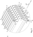
- In 2 is a in 1 shown with II designated section of the end of the droplet separator 1 in enlargement. It can be clearly seen that each spacer 3 is approximately plate-shaped and has an upper edge area 4 and a lower edge area 5 . Both the upper edge area 4 and the lower edge area 5 of the spacers 3 extend essentially perpendicularly to the longitudinal extension L and to the height H of the separator lamellae 3. The two side edges 6, 7 of the spacers 3 have a multiply curved shape that corresponds to the cross section of the Separator lamellae 2 corresponds. The spacers 3 are arranged between the separator lamellae 2, nestle with their side edges 6, 7 on the separator lamellae 2 and keep the separator lamellae 2 spaced apart from one another.
- the spacers 3 between the individual separator lamellae 2 are at the same position in the longitudinal direction L of the separator lamellae 2 and are each surrounded by a rail 8 at their upper edge area 4 and their lower edge area 5 .
- Each rail 8 has a U-shaped cross section and surrounds the respective edge area 4, 5 of the spacers 3 on both sides.
- each rail 8 has a plurality of second locking devices in the form of openings 10 .
- the number of openings 10 in each rail 8 corresponds to the number of spacers 3 enclosed by the respective rail 8 .
- the openings 10 are arranged in the transverse web 11 of the U-shaped rail 8 .
- the position of the openings 10 corresponds approximately to the middle of the spacer 3 arranged underneath.
- Each spacer 3, 3' has on its upper edge area 4 and on its lower edge area 5 a first locking device in the form of a protruding strip 12, 12'.
- the strips 12, 12' lie in one plane with the remaining area of the spacer 3.
- the strips 12, 12' are arranged centrally on the respective edge area 4, 5.
- Each strip 12, 12' extends through one of the openings 10 in the rails 8.
- the strips 12' of every fifth spacer 3' are somewhat longer than the strips 12 of the other spacers 3.
- the longer strips 12' are beaded, ie bent over, and lie on one side of the rail 8 in question.
- the flanged strips 12' of the spacers 3' and the associated openings 10 of the rails 8 form a positive locking mechanism which holds the rails 8, the spacers 3, 3' and the separator lamellae 2 together.
- more or fewer spacers have a strip with a greater length, which is passed through the corresponding opening in the respective rail and crimped.
- the strips of all spacers can be crimped or only the strips of every seventh spacer.
- FIG. 3 shows a side view of a portion of the droplet separator 1 from 1 . This is the side view of one of the areas of the separator lamellae 2 on which spacers 3 are arranged. The upper area of the outermost separator lamella 2 and one of the outermost spacers 3' can be seen. In 3 the spacers 3, 3' are arranged one behind the other in the image plane.
- the U-shaped rail 8 is plugged onto the upper edge region 4 of the spacers 3, 3'.
- the upper strip 12 'of the outermost spacer 3' is passed through the opening 10 of the rail 8 and flanged so that it rests on the outside of the rail 8.
- the separator lamellae 2 arranged parallel and spaced apart from one another have a recess 14 at their upper edge 13 and at their lower edge (not shown), at the position at which the spacers 3 are arranged, into which the U-shaped rails 8 engage .
- the droplet separator 1 is therefore very stable and can be easily handled, transported and assembled.
- the droplet separator 3' is essentially plate-shaped.
- the protruding strips 12' are formed approximately centrally on the upper edge area 4 and on the lower edge area 5 of the spacer 3'.
- the protruding strips 12' lie in the same plane as the rest of the spacer 3'.
- the shape of the side edges 6, 7 of the spacer 3' corresponds to the cross-sectional shape of the separator lamellae 2.
- the side edges 6, 7 of the spacer 3' are therefore also multiply curved.
- the strips 12' have a first length l1, which is sufficient to guide the strips 12' through the corresponding opening 10 in the rail 8 and to bead them, ie to bend them.
- figure 5 shows a further spacer 3, which is in the figures 1 and 2 between two spacers 3' with a longer strip 12' is arranged.
- the spacer 3 is essentially identical in construction to the spacer 3' 4 with the difference that the protruding strip 12 has a second length l2.
- the second length 2 is smaller than the first length l1.
- the spacers 3, 3' are preferably stamped out of sheet metal.
- the protruding elements of which, ie the strips, have a length which differs from the length l1, l2 of the strips 12, 12'. This length is preferably shorter.
- the rail 8 is designed as a profile with a U-shaped cross section.
- the openings 10 through which the strips 12, 12' of the spacers extend are formed in the upper region of the rail 8, that is to say in the transverse web 11 of the U-shaped profile.
- All components of the droplet separator are preferably made of a metallic material.
Landscapes
- Chemical & Material Sciences (AREA)
- Chemical Kinetics & Catalysis (AREA)
- Separating Particles In Gases By Inertia (AREA)
- Filtering Of Dispersed Particles In Gases (AREA)
- Fuel Cell (AREA)
- Filtering Materials (AREA)
- Cell Separators (AREA)
Claims (10)
- Séparateur de gouttes (1) pour séparer des liquides d'un flux de gaz, comprenant au moins deux lamelles de séparation (2) agencées parallèlement l'une à l'autre et au moins un élément d'espacement (3) agencé transversalement à la direction longitudinale (L) des lamelles de séparation (2) et maintenant les lamelles de séparation (2) à une certaine distance l'une de l'autre, un rail (8) étant agencé sur au moins une des zones de bord (4, 5) du au moins un élément d'espacement (3) qui s'étendent transversalement à la direction longitudinale (L) et transversalement à la hauteur (H) des lamelles de séparation (2), le au moins un élément d'espacement (3) présentant au moins un premier dispositif de verrouillage, le rail (8) présentant au moins un second dispositif de verrouillage, et le au moins un premier dispositif de verrouillage et le au moins un second dispositif de verrouillage venant en prise l'un avec l'autre par complémentarité de forme et verrouillant les lamelles de séparation (2) sur le au moins un élément d'espacement (3) et le rail (8), caractérisé en ce que le au moins un premiers dispositif de verrouillage du au moins un élément d'espacement (3) est réalisé en tant qu'élément en saillie ayant la forme d'une bande (12), et le au moins un second dispositif de verrouillage du rail (8) est réalisé en tant que cavité sous la forme d'une ouverture dans le rail (8), à travers laquelle la bande (12, 12') est amenée à passer, et la partie de la bande (12, 12') du au moins un élément d'espacement (3) faisant saillie en dehors de l'ouverture (10) du rail (8) est repliée.
- Séparateur de gouttes (1) selon la revendication 1, caractérisé en ce que le rail (8) présente une section transversale en forme de U et entoure la zone de bord (4, 5) du au moins un élément d'espacement (3).
- Séparateur de gouttes (1) selon la revendication 1 ou 2, caractérisé en ce qu'un rail (8) est agencé sur les deux zones de bord (4, 5) du au moins un élément d'espacement (3) s'étendant transversalement à la direction longitudinale (L) et transversalement à la hauteur (H) des lamelles de séparation (2).
- Séparateur de gouttes (1) selon l'une quelconque des revendications 1 à 3, caractérisé en ce que le au moins un élément d'espacement (3) est réalisé en forme de plaque et l'élément en saillie se trouve dans le plan du au moins un élément d'espacement (3).
- Séparateur de gouttes (1) selon l'une quelconque des revendications précédentes, caractérisé en ce qu'au moins l'une des lamelles de séparation (2) est munie d'un évidement (14) dans lequel le au moins un rail (8) vient en prise.
- Séparateur de gouttes (1) selon l'une quelconque des revendications précédentes, comprenant une pluralité de lamelles de séparation (2) agencée parallèlement les unes aux autres, dans lequel des lamelles de séparation (2) agencées les unes à côté des autres sont maintenues à une certaine distance les unes des autres par des éléments d'espacement (3), et les éléments d'espacement (3) sont agencés les uns à côté des autres transversalement à la direction longitudinale (L) des lamelles de séparation (2), et un rail commun (8) est agencé respectivement sur les deux zones de bord (4, 5) des éléments d'espacement (3) agencés les uns à côté des autres, s'étendent transversalement à la direction longitudinale (L) et transversalement à la hauteur (H) des lamelles de séparation (2), dans lequel chacune des éléments d'espacement (3) présente une bande en saillie (12, 12') sur sa zone de bord supérieure (4) et sur sa zone de bord inférieure (5), et les bandes en saillie (12, 12') viennent en prise dans des ouvertures correspondantes (10) dans le rail respectif (8).
- Séparateur de gouttes (1) selon la revendication 6, caractérisé en ce que plusieurs éléments d'espacement (3) sont agencés sur chaque lamelle de séparation (2) à une certaine distance les unes des autres dans la direction longitudinale (L) des lamelles de séparation (2), les éléments d'espacement (3) de lamelles de séparation (2) les unes à côté des autres, qui se trouvent dans la même position dans la direction longitudinale (L) des lamelles de séparation (2), étant respectivement verrouillés par un rail commun (8) sur les deux zones de bord (4, 5) s'étendant transversalement à la direction longitudinale (L) et transversalement à la hauteur (H) des lamelles de séparation (2).
- Séparateur de gouttes (1) selon l'une quelconque des revendications précédentes, caractérisé en ce que les bandes (12, 12') des éléments d'espacement (3) présentent une longueur différente.
- Séparateur de gouttes (1) selon l'une des revendications 6 à 8, caractérisé en ce que seules certaines des bandes en saillie (12, 12') des éléments d'espacement (3) sont repliées.
- Séparateur de gouttes (1) selon l'une des revendications précédentes, caractérisé en ce que le séparateur de gouttes (1) est constitué de matériaux métalliques.
Applications Claiming Priority (1)
| Application Number | Priority Date | Filing Date | Title |
|---|---|---|---|
| DE102018133150.9A DE102018133150A1 (de) | 2018-12-20 | 2018-12-20 | Tropfenabscheider mit neuer Verbindungsstruktur |
Publications (2)
| Publication Number | Publication Date |
|---|---|
| EP3669963A1 EP3669963A1 (fr) | 2020-06-24 |
| EP3669963B1 true EP3669963B1 (fr) | 2022-02-02 |
Family
ID=68944546
Family Applications (1)
| Application Number | Title | Priority Date | Filing Date |
|---|---|---|---|
| EP19217365.6A Active EP3669963B1 (fr) | 2018-12-20 | 2019-12-18 | Séparateur de gouttes dotée d'une nouvelle structure de raccordement |
Country Status (7)
| Country | Link |
|---|---|
| EP (1) | EP3669963B1 (fr) |
| KR (1) | KR102343316B1 (fr) |
| CN (1) | CN111346432B (fr) |
| DE (1) | DE102018133150A1 (fr) |
| DK (1) | DK3669963T3 (fr) |
| ES (1) | ES2909194T3 (fr) |
| TW (1) | TWI787563B (fr) |
Family Cites Families (18)
| Publication number | Priority date | Publication date | Assignee | Title |
|---|---|---|---|---|
| ZA801332B (en) * | 1979-07-26 | 1981-08-26 | Xerxes Fiberglass Inc | Liquid eliminator |
| DE3039780A1 (de) * | 1980-10-22 | 1982-05-13 | GEA Kühlturmbau und Luftkondensation GmbH, 4630 Bochum | Tropfenfang |
| DE8218913U1 (de) * | 1982-07-02 | 1982-08-26 | Gesellschaft für Verfahrenstechnik mbH & Co KG, 4220 Dinslaken | Tropfenabscheider fuer luftwaescher, luftkuehler u. dgl. |
| DE19501282C2 (de) * | 1995-01-18 | 1998-07-09 | Munters Euroform Gmbh Carl | Tropfenabscheider sowie Lamellenhalter hierfür |
| DE20210293U1 (de) * | 2002-07-03 | 2002-09-05 | Ahrens, Adolf, 59510 Lippetal | Austauschbare Kassetten für Tropfenabscheider in Rauchgasentschwefelungsanlagen |
| DE102011081667A1 (de) * | 2011-08-26 | 2013-02-28 | Siemens Aktiengesellschaft | Lamellenabscheider |
| DE102011081663A1 (de) * | 2011-08-26 | 2013-02-28 | Siemens Aktiengesellschaft | Lamellenabscheider |
| DE202011106925U1 (de) * | 2011-10-18 | 2011-12-13 | Munters Euroform Gmbh | Tropfenabscheiderpaket mit verrastbaren Halteleisten |
| CN202682935U (zh) * | 2012-07-05 | 2013-01-23 | 上海瑞亚安环保设备有限公司 | 除雾器片间隔固定结构 |
| KR20140001617U (ko) * | 2012-09-11 | 2014-03-19 | 한발매스테크 주식회사 | 다중 포켓 플레이트 형 미스트 엘리미네이트의 구조. |
| CN203556218U (zh) * | 2013-09-21 | 2014-04-23 | 浙江宏电环保科技有限公司 | 一种除雾器叶片固定装置 |
| CN104888554B (zh) * | 2015-05-19 | 2016-06-29 | 北京化工大学常州先进材料研究院 | 一种除尘器 |
| CN204865263U (zh) * | 2015-06-02 | 2015-12-16 | 枣强县莱伯特环保设备有限公司 | 玻璃钢折流板除雾器 |
| CN205235588U (zh) * | 2015-12-17 | 2016-05-18 | 南京新世纪江南环保科技发展有限公司 | 一种除雾器固定件 |
| CN205549900U (zh) * | 2016-03-11 | 2016-09-07 | 河南晋开化工投资控股集团有限责任公司 | 新型高效除雾器 |
| DE102017001414B4 (de) | 2017-02-14 | 2020-06-10 | Munters Euroform Gmbh | Tropfenabscheider mit Steckverbindungen |
| DE102017001415A1 (de) * | 2017-02-14 | 2018-08-16 | Munters Euroform Gmbh | Tropfenabscheider mit geringer Bauhöhe |
| CN207385093U (zh) * | 2017-09-05 | 2018-05-22 | 上海超惠通风环保设备有限公司 | 一种防静电耐高温高效除雾器 |
-
2018
- 2018-12-20 DE DE102018133150.9A patent/DE102018133150A1/de not_active Withdrawn
-
2019
- 2019-12-05 TW TW108144588A patent/TWI787563B/zh active
- 2019-12-18 DK DK19217365.6T patent/DK3669963T3/da active
- 2019-12-18 EP EP19217365.6A patent/EP3669963B1/fr active Active
- 2019-12-18 ES ES19217365T patent/ES2909194T3/es active Active
- 2019-12-19 CN CN201911317279.5A patent/CN111346432B/zh active Active
- 2019-12-20 KR KR1020190171546A patent/KR102343316B1/ko active Active
Also Published As
| Publication number | Publication date |
|---|---|
| KR102343316B1 (ko) | 2021-12-23 |
| DK3669963T3 (da) | 2022-02-14 |
| TWI787563B (zh) | 2022-12-21 |
| ES2909194T3 (es) | 2022-05-05 |
| EP3669963A1 (fr) | 2020-06-24 |
| CN111346432A (zh) | 2020-06-30 |
| DE102018133150A1 (de) | 2020-06-25 |
| TW202031338A (zh) | 2020-09-01 |
| KR20200077452A (ko) | 2020-06-30 |
| CN111346432B (zh) | 2021-10-15 |
Similar Documents
| Publication | Publication Date | Title |
|---|---|---|
| EP3957940B1 (fr) | Module d'échangeur de chaleur à plaque à contre-courant et échangeur de chaleur à plaque à contre-courant | |
| EP2768596B1 (fr) | Paquet d'éléments de dépôt de gouttes présentant des barres de retenue encliquetables | |
| DE2418132C2 (de) | Wärmetauscher, insbesondere Kühler für Kraftfahrzeuge | |
| DE3928234C1 (fr) | ||
| EP2334887B1 (fr) | Connecteur à fiche | |
| EP1042578A1 (fr) | Connecteur multiple pour profiles creux | |
| DE9310827U1 (de) | Waermetauscher aus mehreren parallel zueinander angeordneten austauscherrohren | |
| EP0340242B1 (fr) | Separateur pour fluides gazeux | |
| EP3255369A1 (fr) | Élément d'ailletes pour un échangeur de chaleur | |
| EP3669963B1 (fr) | Séparateur de gouttes dotée d'une nouvelle structure de raccordement | |
| DE2935158B2 (de) | Stranggepreßtes Bauelement zum Aufbau von Wänden, insbesondere von Kraftfahrzeugen | |
| DE69404108T2 (de) | Wärmetauscher, insbesondere als Ölkühler benutzt | |
| EP0401590B1 (fr) | Echangeur de chaleur | |
| EP1458455B1 (fr) | Profile de retenue pour lamelles, unite de profile de retenue modulaire et unite de separation, de reduction de lumiere ou de conduction de flux ainsi equipee | |
| EP0687790B1 (fr) | Raccord rectiligne pour profilés intercalaires creux de vitrages isolants | |
| EP0944132B1 (fr) | Serre câble | |
| DE19858325B4 (de) | Wärmeübertrageranordnung für ein Kraftfahrzeug | |
| DE2851316A1 (de) | Element zum direkten und/oder indirekten waermeaustausch zwischen fluiden | |
| DE19816623C2 (de) | Spritzwandmodul und aus Spritzwandmodulen aufgebaute Spritzwand | |
| DE19501282A1 (de) | Tropfenabscheider sowie Lamellenhalter hierfür | |
| DE102006011152B4 (de) | Tropfenabscheideranordnung | |
| EP1650520A2 (fr) | Dispositif d'échange de chaleur | |
| DE7835175U1 (de) | Element zur direkten und/oder indirekten waermeaustausch zwischen fluiden | |
| DE3539888A1 (de) | Halteleiste fuer platten | |
| DE20317987U1 (de) | Lüftungsgitter zum Be- und/oder Entlüften eines Raumes |
Legal Events
| Date | Code | Title | Description |
|---|---|---|---|
| PUAI | Public reference made under article 153(3) epc to a published international application that has entered the european phase |
Free format text: ORIGINAL CODE: 0009012 |
|
| STAA | Information on the status of an ep patent application or granted ep patent |
Free format text: STATUS: THE APPLICATION HAS BEEN PUBLISHED |
|
| AK | Designated contracting states |
Kind code of ref document: A1 Designated state(s): AL AT BE BG CH CY CZ DE DK EE ES FI FR GB GR HR HU IE IS IT LI LT LU LV MC MK MT NL NO PL PT RO RS SE SI SK SM TR |
|
| AX | Request for extension of the european patent |
Extension state: BA ME |
|
| STAA | Information on the status of an ep patent application or granted ep patent |
Free format text: STATUS: REQUEST FOR EXAMINATION WAS MADE |
|
| 17P | Request for examination filed |
Effective date: 20201218 |
|
| RBV | Designated contracting states (corrected) |
Designated state(s): AL AT BE BG CH CY CZ DE DK EE ES FI FR GB GR HR HU IE IS IT LI LT LU LV MC MK MT NL NO PL PT RO RS SE SI SK SM TR |
|
| STAA | Information on the status of an ep patent application or granted ep patent |
Free format text: STATUS: EXAMINATION IS IN PROGRESS |
|
| 17Q | First examination report despatched |
Effective date: 20210311 |
|
| GRAP | Despatch of communication of intention to grant a patent |
Free format text: ORIGINAL CODE: EPIDOSNIGR1 |
|
| STAA | Information on the status of an ep patent application or granted ep patent |
Free format text: STATUS: GRANT OF PATENT IS INTENDED |
|
| INTG | Intention to grant announced |
Effective date: 20210809 |
|
| GRAS | Grant fee paid |
Free format text: ORIGINAL CODE: EPIDOSNIGR3 |
|
| GRAA | (expected) grant |
Free format text: ORIGINAL CODE: 0009210 |
|
| STAA | Information on the status of an ep patent application or granted ep patent |
Free format text: STATUS: THE PATENT HAS BEEN GRANTED |
|
| AK | Designated contracting states |
Kind code of ref document: B1 Designated state(s): AL AT BE BG CH CY CZ DE DK EE ES FI FR GB GR HR HU IE IS IT LI LT LU LV MC MK MT NL NO PL PT RO RS SE SI SK SM TR |
|
| REG | Reference to a national code |
Ref country code: GB Ref legal event code: FG4D Free format text: NOT ENGLISH |
|
| REG | Reference to a national code |
Ref country code: DK Ref legal event code: T3 Effective date: 20220210 |
|
| REG | Reference to a national code |
Ref country code: CH Ref legal event code: EP Ref country code: AT Ref legal event code: REF Ref document number: 1466437 Country of ref document: AT Kind code of ref document: T Effective date: 20220215 |
|
| REG | Reference to a national code |
Ref country code: DE Ref legal event code: R096 Ref document number: 502019003365 Country of ref document: DE |
|
| REG | Reference to a national code |
Ref country code: IE Ref legal event code: FG4D Free format text: LANGUAGE OF EP DOCUMENT: GERMAN |
|
| REG | Reference to a national code |
Ref country code: FI Ref legal event code: FGE |
|
| REG | Reference to a national code |
Ref country code: SE Ref legal event code: TRGR |
|
| REG | Reference to a national code |
Ref country code: NO Ref legal event code: T2 Effective date: 20220202 |
|
| REG | Reference to a national code |
Ref country code: NL Ref legal event code: FP |
|
| REG | Reference to a national code |
Ref country code: ES Ref legal event code: FG2A Ref document number: 2909194 Country of ref document: ES Kind code of ref document: T3 Effective date: 20220505 |
|
| REG | Reference to a national code |
Ref country code: LT Ref legal event code: MG9D |
|
| PG25 | Lapsed in a contracting state [announced via postgrant information from national office to epo] |
Ref country code: RS Free format text: LAPSE BECAUSE OF FAILURE TO SUBMIT A TRANSLATION OF THE DESCRIPTION OR TO PAY THE FEE WITHIN THE PRESCRIBED TIME-LIMIT Effective date: 20220202 Ref country code: PT Free format text: LAPSE BECAUSE OF FAILURE TO SUBMIT A TRANSLATION OF THE DESCRIPTION OR TO PAY THE FEE WITHIN THE PRESCRIBED TIME-LIMIT Effective date: 20220602 Ref country code: LT Free format text: LAPSE BECAUSE OF FAILURE TO SUBMIT A TRANSLATION OF THE DESCRIPTION OR TO PAY THE FEE WITHIN THE PRESCRIBED TIME-LIMIT Effective date: 20220202 Ref country code: HR Free format text: LAPSE BECAUSE OF FAILURE TO SUBMIT A TRANSLATION OF THE DESCRIPTION OR TO PAY THE FEE WITHIN THE PRESCRIBED TIME-LIMIT Effective date: 20220202 Ref country code: BG Free format text: LAPSE BECAUSE OF FAILURE TO SUBMIT A TRANSLATION OF THE DESCRIPTION OR TO PAY THE FEE WITHIN THE PRESCRIBED TIME-LIMIT Effective date: 20220502 |
|
| PG25 | Lapsed in a contracting state [announced via postgrant information from national office to epo] |
Ref country code: PL Free format text: LAPSE BECAUSE OF FAILURE TO SUBMIT A TRANSLATION OF THE DESCRIPTION OR TO PAY THE FEE WITHIN THE PRESCRIBED TIME-LIMIT Effective date: 20220202 Ref country code: LV Free format text: LAPSE BECAUSE OF FAILURE TO SUBMIT A TRANSLATION OF THE DESCRIPTION OR TO PAY THE FEE WITHIN THE PRESCRIBED TIME-LIMIT Effective date: 20220202 Ref country code: GR Free format text: LAPSE BECAUSE OF FAILURE TO SUBMIT A TRANSLATION OF THE DESCRIPTION OR TO PAY THE FEE WITHIN THE PRESCRIBED TIME-LIMIT Effective date: 20220503 |
|
| PG25 | Lapsed in a contracting state [announced via postgrant information from national office to epo] |
Ref country code: IS Free format text: LAPSE BECAUSE OF FAILURE TO SUBMIT A TRANSLATION OF THE DESCRIPTION OR TO PAY THE FEE WITHIN THE PRESCRIBED TIME-LIMIT Effective date: 20220602 |
|
| PG25 | Lapsed in a contracting state [announced via postgrant information from national office to epo] |
Ref country code: SM Free format text: LAPSE BECAUSE OF FAILURE TO SUBMIT A TRANSLATION OF THE DESCRIPTION OR TO PAY THE FEE WITHIN THE PRESCRIBED TIME-LIMIT Effective date: 20220202 Ref country code: SK Free format text: LAPSE BECAUSE OF FAILURE TO SUBMIT A TRANSLATION OF THE DESCRIPTION OR TO PAY THE FEE WITHIN THE PRESCRIBED TIME-LIMIT Effective date: 20220202 Ref country code: RO Free format text: LAPSE BECAUSE OF FAILURE TO SUBMIT A TRANSLATION OF THE DESCRIPTION OR TO PAY THE FEE WITHIN THE PRESCRIBED TIME-LIMIT Effective date: 20220202 Ref country code: EE Free format text: LAPSE BECAUSE OF FAILURE TO SUBMIT A TRANSLATION OF THE DESCRIPTION OR TO PAY THE FEE WITHIN THE PRESCRIBED TIME-LIMIT Effective date: 20220202 Ref country code: CZ Free format text: LAPSE BECAUSE OF FAILURE TO SUBMIT A TRANSLATION OF THE DESCRIPTION OR TO PAY THE FEE WITHIN THE PRESCRIBED TIME-LIMIT Effective date: 20220202 |
|
| REG | Reference to a national code |
Ref country code: DE Ref legal event code: R097 Ref document number: 502019003365 Country of ref document: DE |
|
| PG25 | Lapsed in a contracting state [announced via postgrant information from national office to epo] |
Ref country code: AL Free format text: LAPSE BECAUSE OF FAILURE TO SUBMIT A TRANSLATION OF THE DESCRIPTION OR TO PAY THE FEE WITHIN THE PRESCRIBED TIME-LIMIT Effective date: 20220202 |
|
| PLBE | No opposition filed within time limit |
Free format text: ORIGINAL CODE: 0009261 |
|
| STAA | Information on the status of an ep patent application or granted ep patent |
Free format text: STATUS: NO OPPOSITION FILED WITHIN TIME LIMIT |
|
| 26N | No opposition filed |
Effective date: 20221103 |
|
| PG25 | Lapsed in a contracting state [announced via postgrant information from national office to epo] |
Ref country code: SI Free format text: LAPSE BECAUSE OF FAILURE TO SUBMIT A TRANSLATION OF THE DESCRIPTION OR TO PAY THE FEE WITHIN THE PRESCRIBED TIME-LIMIT Effective date: 20220202 |
|
| PG25 | Lapsed in a contracting state [announced via postgrant information from national office to epo] |
Ref country code: LU Free format text: LAPSE BECAUSE OF NON-PAYMENT OF DUE FEES Effective date: 20221218 |
|
| PG25 | Lapsed in a contracting state [announced via postgrant information from national office to epo] |
Ref country code: IE Free format text: LAPSE BECAUSE OF NON-PAYMENT OF DUE FEES Effective date: 20221218 |
|
| PG25 | Lapsed in a contracting state [announced via postgrant information from national office to epo] |
Ref country code: HU Free format text: LAPSE BECAUSE OF FAILURE TO SUBMIT A TRANSLATION OF THE DESCRIPTION OR TO PAY THE FEE WITHIN THE PRESCRIBED TIME-LIMIT; INVALID AB INITIO Effective date: 20191218 |
|
| PG25 | Lapsed in a contracting state [announced via postgrant information from national office to epo] |
Ref country code: CY Free format text: LAPSE BECAUSE OF FAILURE TO SUBMIT A TRANSLATION OF THE DESCRIPTION OR TO PAY THE FEE WITHIN THE PRESCRIBED TIME-LIMIT Effective date: 20220202 |
|
| PG25 | Lapsed in a contracting state [announced via postgrant information from national office to epo] |
Ref country code: MK Free format text: LAPSE BECAUSE OF FAILURE TO SUBMIT A TRANSLATION OF THE DESCRIPTION OR TO PAY THE FEE WITHIN THE PRESCRIBED TIME-LIMIT Effective date: 20220202 |
|
| PG25 | Lapsed in a contracting state [announced via postgrant information from national office to epo] |
Ref country code: MC Free format text: LAPSE BECAUSE OF FAILURE TO SUBMIT A TRANSLATION OF THE DESCRIPTION OR TO PAY THE FEE WITHIN THE PRESCRIBED TIME-LIMIT Effective date: 20220202 |
|
| PG25 | Lapsed in a contracting state [announced via postgrant information from national office to epo] |
Ref country code: MC Free format text: LAPSE BECAUSE OF FAILURE TO SUBMIT A TRANSLATION OF THE DESCRIPTION OR TO PAY THE FEE WITHIN THE PRESCRIBED TIME-LIMIT Effective date: 20220202 |
|
| GBPC | Gb: european patent ceased through non-payment of renewal fee |
Effective date: 20231218 |
|
| PG25 | Lapsed in a contracting state [announced via postgrant information from national office to epo] |
Ref country code: MT Free format text: LAPSE BECAUSE OF FAILURE TO SUBMIT A TRANSLATION OF THE DESCRIPTION OR TO PAY THE FEE WITHIN THE PRESCRIBED TIME-LIMIT Effective date: 20220202 |
|
| PG25 | Lapsed in a contracting state [announced via postgrant information from national office to epo] |
Ref country code: GB Free format text: LAPSE BECAUSE OF NON-PAYMENT OF DUE FEES Effective date: 20231218 |
|
| PG25 | Lapsed in a contracting state [announced via postgrant information from national office to epo] |
Ref country code: GB Free format text: LAPSE BECAUSE OF NON-PAYMENT OF DUE FEES Effective date: 20231218 |
|
| PG25 | Lapsed in a contracting state [announced via postgrant information from national office to epo] |
Ref country code: TR Free format text: LAPSE BECAUSE OF FAILURE TO SUBMIT A TRANSLATION OF THE DESCRIPTION OR TO PAY THE FEE WITHIN THE PRESCRIBED TIME-LIMIT Effective date: 20220202 |
|
| REG | Reference to a national code |
Ref country code: CH Ref legal event code: U11 Free format text: ST27 STATUS EVENT CODE: U-0-0-U10-U11 (AS PROVIDED BY THE NATIONAL OFFICE) Effective date: 20260101 |
|
| PGFP | Annual fee paid to national office [announced via postgrant information from national office to epo] |
Ref country code: NO Payment date: 20251222 Year of fee payment: 7 |
|
| PGFP | Annual fee paid to national office [announced via postgrant information from national office to epo] |
Ref country code: AT Payment date: 20251222 Year of fee payment: 7 |
|
| PGFP | Annual fee paid to national office [announced via postgrant information from national office to epo] |
Ref country code: FI Payment date: 20251227 Year of fee payment: 7 Ref country code: DK Payment date: 20251223 Year of fee payment: 7 |
|
| PGFP | Annual fee paid to national office [announced via postgrant information from national office to epo] |
Ref country code: NL Payment date: 20251223 Year of fee payment: 7 Ref country code: FR Payment date: 20251223 Year of fee payment: 7 |
|
| PGFP | Annual fee paid to national office [announced via postgrant information from national office to epo] |
Ref country code: BE Payment date: 20251222 Year of fee payment: 7 |
|
| PGFP | Annual fee paid to national office [announced via postgrant information from national office to epo] |
Ref country code: SE Payment date: 20251223 Year of fee payment: 7 |
|
| PGFP | Annual fee paid to national office [announced via postgrant information from national office to epo] |
Ref country code: ES Payment date: 20260102 Year of fee payment: 7 |
|
| PGFP | Annual fee paid to national office [announced via postgrant information from national office to epo] |
Ref country code: DE Payment date: 20251223 Year of fee payment: 7 |
|
| PGFP | Annual fee paid to national office [announced via postgrant information from national office to epo] |
Ref country code: IT Payment date: 20251229 Year of fee payment: 7 |
|
| PGFP | Annual fee paid to national office [announced via postgrant information from national office to epo] |
Ref country code: CH Payment date: 20260101 Year of fee payment: 7 |