EP0340242B1 - Separateur pour fluides gazeux - Google Patents
Separateur pour fluides gazeux Download PDFInfo
- Publication number
- EP0340242B1 EP0340242B1 EP88901148A EP88901148A EP0340242B1 EP 0340242 B1 EP0340242 B1 EP 0340242B1 EP 88901148 A EP88901148 A EP 88901148A EP 88901148 A EP88901148 A EP 88901148A EP 0340242 B1 EP0340242 B1 EP 0340242B1
- Authority
- EP
- European Patent Office
- Prior art keywords
- profile
- profile parts
- projections
- fluids
- holding devices
- Prior art date
- Legal status (The legal status is an assumption and is not a legal conclusion. Google has not performed a legal analysis and makes no representation as to the accuracy of the status listed.)
- Expired - Lifetime
Links
Images
Classifications
-
- B—PERFORMING OPERATIONS; TRANSPORTING
- B01—PHYSICAL OR CHEMICAL PROCESSES OR APPARATUS IN GENERAL
- B01D—SEPARATION
- B01D45/00—Separating dispersed particles from gases or vapours by gravity, inertia, or centrifugal forces
- B01D45/04—Separating dispersed particles from gases or vapours by gravity, inertia, or centrifugal forces by utilising inertia
- B01D45/08—Separating dispersed particles from gases or vapours by gravity, inertia, or centrifugal forces by utilising inertia by impingement against baffle separators
Definitions
- the invention relates to a separator according to the preamble of claim 1.
- a corresponding separator can be found in EP-A-O 206 204.
- a corresponding separator offers an increased degree of separation compared to others, and there is also the advantage that the profile parts can be cleaned without any problems, since they can basically be replaced individually.
- Characteristic of corresponding separators is the presence of the protrusion, which is to be referred to as the inner protrusion, from the apex region of the inner surface of the protruding protrusion, which is preferably drop-shaped or knob-like, whereby chambers are formed in the region of each profile part, which influence the flow velocity of the fluids flowing through the separator .
- the degree of separation is increased in an unexpected manner.
- the object of the present invention is to design a separator of the type mentioned at the outset in such a way that the degree of separation can be adjusted in a controlled manner in the case of predetermined profile partial cross sections is and in particular in the area in which increased amounts of fluids to be cleaned occur, increased separation takes place, whereas normal separation conditions can be selected in the remaining area.
- a separator is accordingly made available in which the distance between the intermeshing rows of first and second profile parts is adjustable.
- the chambers forming between the interlocking profile parts and the internal projections can be changed such that the flow rate of the fluids to be extracted can be adjusted to the desired extent, thereby influencing the degree of separation.
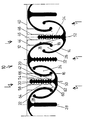
- a section of a separator (10) which comprises trough-shaped open profile parts (12), (14), the edges (16), (18) and (20), (22) of which engage behind one another such that chambers form between the narrowing of the edges, two of which are designated by way of example with the reference numerals (24) and (26) in the exemplary embodiment.
- the profile parts (12) and (14) have projections (28), (30), (32) and (34) extending from the inner surface in the direction of the longitudinal axis, as a result of which further chambers to the adjacent inner surface or to the edge of the adjacent profile part.
- chambers are provided with the reference symbols (36) and (38).
- the interlocking profile parts (12) and (14) arranged in rows are used to clean gaseous fluids such as cooling fluids, oil mists, air containing dirt particles and thus form the separator (10) in a row.
- the projections (28), (30), (32), (34) not only serve to form further chambers (36), (38) acting on the fluids, but also give each profile part (14), (16) a high profile Inherent rigidity. As a result, the profile parts (14), (16) of great length can be accommodated without additional supports of holding elements, which are described in more detail below.
- the holding elements which grip the profile parts (14), (16), start from a plate-shaped base element (40), from which strip-shaped sections extend, specifically for holding the profile parts (12), strip-shaped sections (42) and (44) and Holding the profile parts (14) strip-shaped sections (46) and (48).
- the strip-shaped sections (42) and (44) encompass the outer surface of the profile part (12) at least in sections, a resilient design being selected to ensure secure attachment without, however, an exchange of the profile parts being no longer possible, and at the same time Operation of the separator (10) vibrations leading to noise are excluded.
- Sections (42), (44) can be used with projecting locking hooks (50), (52) interact on the outer surface of the profile part (12), thereby increasing the fastening.
- the projections (30) and (34) are profiled in order to interact with the sections (46) and (48) in different positions.
- the projections (30) and (34) preferably have recesses (54) or projections (58) running in the longitudinal direction, that is to say they show a zigzag structure in cross section on the longitudinal sides.
- the likewise resilient sections (46) and (48) are provided with projections (60), (62) and (64), (66) which snap into the recesses (54).
- each section (46), (48) has two latching projections (60), (64) and (62), (66) for secure fastening, so that the projection (30) is spaced apart at two locations. or (34) interact.
- the focus can be increased by changing the volume of the chambers that form between the profile parts or the inner projections and the adjacent profile parts.
- an increased deposition can be expected compared to the area adjacent to the projection (34).
- a corresponding design of the separator (10) has considerable advantages, particularly in industrial companies, since the separation rate can be increased in a targeted manner in the areas in which increased quantities of fluids to be cleaned are obtained, whereas normal separation is sufficient in other areas.
- the air throughput can also be set to normal conditions with a separator according to the invention, which can extend over the entire ceiling of a production hall, if an increased extraction is required at certain points, which according to the invention is due to the spacing of the interlocking rows of profile parts (12 ), (14) is made possible.
Landscapes
- Chemical & Material Sciences (AREA)
- Chemical Kinetics & Catalysis (AREA)
- Separating Particles In Gases By Inertia (AREA)
- Separation Using Semi-Permeable Membranes (AREA)
- Spinning Methods And Devices For Manufacturing Artificial Fibers (AREA)
Claims (3)
Priority Applications (1)
| Application Number | Priority Date | Filing Date | Title |
|---|---|---|---|
| AT88901148T ATE61527T1 (de) | 1987-01-01 | 1987-12-29 | Abscheider fuer gasfoermige fluide. |
Applications Claiming Priority (2)
| Application Number | Priority Date | Filing Date | Title |
|---|---|---|---|
| DE8700012U DE8700012U1 (de) | 1987-01-01 | 1987-01-01 | Abscheider |
| DE8700012U | 1987-01-01 |
Publications (2)
| Publication Number | Publication Date |
|---|---|
| EP0340242A1 EP0340242A1 (fr) | 1989-11-08 |
| EP0340242B1 true EP0340242B1 (fr) | 1991-03-13 |
Family
ID=6803215
Family Applications (1)
| Application Number | Title | Priority Date | Filing Date |
|---|---|---|---|
| EP88901148A Expired - Lifetime EP0340242B1 (fr) | 1987-01-01 | 1987-12-29 | Separateur pour fluides gazeux |
Country Status (5)
| Country | Link |
|---|---|
| EP (1) | EP0340242B1 (fr) |
| JP (1) | JP2526280B2 (fr) |
| AT (1) | ATE61527T1 (fr) |
| DE (2) | DE8700012U1 (fr) |
| WO (1) | WO1988004952A1 (fr) |
Families Citing this family (14)
| Publication number | Priority date | Publication date | Assignee | Title |
|---|---|---|---|---|
| DE4016582A1 (de) * | 1990-05-23 | 1991-11-28 | Rentschler Reven Lueftungssyst | Abscheider fuer fluessigkeiten aus einem gasstrom, insbesondere fuer oelnebel |
| DE9013468U1 (de) * | 1990-09-25 | 1991-02-21 | Gutermuth Sen., Paul, 6456 Langenselbold | Abscheider |
| DE19623177C2 (de) * | 1996-06-10 | 1999-03-11 | Helmut Kittler | Abscheider zum Abscheiden von Flüssigkeiten, insbesondere von Schadstoffen, aus einem Gasstrom |
| DE19623178C2 (de) * | 1996-06-10 | 1999-07-15 | Helmut Kittler | Abscheider zum Abscheiden von Flüssigkeiten, insbesondere von Schadstoffen, aus einem Gasstrom |
| ITBO20020654A1 (it) * | 2002-10-17 | 2004-04-18 | Tiziana Befera | Dispositivo di filtraggio per cappe filtranti e/o aspiranti |
| DE102005038257B4 (de) * | 2005-08-12 | 2010-04-08 | Reinz-Dichtungs-Gmbh | Ölabscheider |
| DE102006023236B4 (de) * | 2006-05-18 | 2015-03-12 | Hans Schmalhofer | Aerosolabscheider |
| DE102008064042B4 (de) | 2008-12-19 | 2011-06-01 | Rentschler Reven-Lüftungssysteme GmbH | Plattenförmiger Abscheider für Flüssigkeiten aus einem Gasstrom |
| DE102009022459A1 (de) * | 2009-04-02 | 2010-10-07 | Volker Haas | Vorabscheider für die An- bzw. Absaugöffnung von Sprühnebel-Absauganlagen, Lackieranlagen u. dgl. |
| JP2013086064A (ja) * | 2011-10-21 | 2013-05-13 | Trinity Industrial Co Ltd | 塗装設備用の水滴捕集装置 |
| KR101301388B1 (ko) | 2012-05-07 | 2013-08-28 | 주식회사 포스코 | 압연유 흄 회수장치 |
| CN107781881B (zh) * | 2017-11-21 | 2020-10-27 | 西安交通大学 | 一种油烟道防倒灌排风弯管 |
| PL71794Y1 (pl) * | 2019-01-04 | 2021-02-08 | Stalgast Radom Spolka Z Ograniczona Odpowiedzialnoscia | Filtr okapu kuchennego |
| WO2021179105A1 (fr) * | 2020-03-08 | 2021-09-16 | 深圳市迪尔安科技有限公司 | Dispositif d'élimination d'huile pour hotte de cuisine |
Family Cites Families (2)
| Publication number | Priority date | Publication date | Assignee | Title |
|---|---|---|---|---|
| DE3507306C1 (de) * | 1985-03-01 | 1986-08-14 | Paul 6456 Langenselbold Gutermuth Sen. | Unterdecke |
| DE3542358A1 (de) * | 1985-06-19 | 1987-01-02 | Sen Paul Gutermuth | Abscheider fuer gasfoermige fluide |
-
1987
- 1987-01-01 DE DE8700012U patent/DE8700012U1/de not_active Expired
- 1987-12-29 WO PCT/EP1987/000826 patent/WO1988004952A1/fr not_active Ceased
- 1987-12-29 EP EP88901148A patent/EP0340242B1/fr not_active Expired - Lifetime
- 1987-12-29 JP JP63501371A patent/JP2526280B2/ja not_active Expired - Lifetime
- 1987-12-29 DE DE8888901148T patent/DE3768662D1/de not_active Expired - Lifetime
- 1987-12-29 AT AT88901148T patent/ATE61527T1/de not_active IP Right Cessation
Also Published As
| Publication number | Publication date |
|---|---|
| EP0340242A1 (fr) | 1989-11-08 |
| DE3768662D1 (de) | 1991-04-18 |
| ATE61527T1 (de) | 1991-03-15 |
| JPH02501809A (ja) | 1990-06-21 |
| WO1988004952A1 (fr) | 1988-07-14 |
| DE8700012U1 (de) | 1987-03-26 |
| JP2526280B2 (ja) | 1996-08-21 |
Similar Documents
| Publication | Publication Date | Title |
|---|---|---|
| EP0340242B1 (fr) | Separateur pour fluides gazeux | |
| DE69907662T2 (de) | Plattenwärmetauscher | |
| EP0151693B1 (fr) | Colonne d'échange de matière | |
| DE3855049T2 (de) | Wärmetauscher für einen Kühlturm | |
| DE3521914A1 (de) | Waermetauscher in fluegelplattenbauweise | |
| EP0112978A1 (fr) | Distributeur de liquide pour une colonne d'échange de masse et ou de chaleur | |
| EP0118800A2 (fr) | Panneau de criblage avec éléments de criblage remplaçables | |
| DE69617811T2 (de) | Strukturierte Packung | |
| EP3255369A1 (fr) | Élément d'ailletes pour un échangeur de chaleur | |
| EP0844454A1 (fr) | Echangeur de chaleur à contre courant | |
| DE4001548A1 (de) | Vorrichtung zum abscheiden von fluiden | |
| EP2182600B1 (fr) | Canal de guidage de conduite doté d'une possibilité de montage du couvercle affleurant ou en retrait | |
| EP0401590B1 (fr) | Echangeur de chaleur | |
| DE19501282C2 (de) | Tropfenabscheider sowie Lamellenhalter hierfür | |
| DE102018006436A1 (de) | Wärmetauscherplatine mit Rechteckprofil und Aufsitzecke | |
| EP0199924B1 (fr) | Gouttière de support pour éléments de plafond | |
| DE102012007873B4 (de) | Lamellenabscheider mit Auffangwanne | |
| EP3669963B1 (fr) | Séparateur de gouttes dotée d'une nouvelle structure de raccordement | |
| DE19746772B4 (de) | Verdampfer mit verbessertem Plattenpaket für eine Klimaanlage, insbesondere von Kraftfahrzeugen | |
| DE1451278A1 (de) | Waermeaustauscher oder Filter mit plattenfoermigen Elementen | |
| DE3527054A1 (de) | Waermetauscher, insbesondere wasser/luftkuehler fuer verbrennungskraftmaschinen | |
| EP1650520A2 (fr) | Dispositif d'échange de chaleur | |
| DE20211500U1 (de) | Filtereinsatz mit einer zu einem Faltenbalg gefalteten Filtermatte und Seitenwänden | |
| DE2105718A1 (de) | Schlitzlüfter für den Einbau in Gebäudedecken | |
| DE7704640U1 (de) | Tragschiene zur klemmbefestigung von paneelen |
Legal Events
| Date | Code | Title | Description |
|---|---|---|---|
| PUAI | Public reference made under article 153(3) epc to a published international application that has entered the european phase |
Free format text: ORIGINAL CODE: 0009012 |
|
| 17P | Request for examination filed |
Effective date: 19890615 |
|
| AK | Designated contracting states |
Kind code of ref document: A1 Designated state(s): AT BE CH DE FR GB IT LI LU NL SE |
|
| 17Q | First examination report despatched |
Effective date: 19900522 |
|
| GRAA | (expected) grant |
Free format text: ORIGINAL CODE: 0009210 |
|
| AK | Designated contracting states |
Kind code of ref document: B1 Designated state(s): AT BE CH DE FR GB IT LI LU NL SE |
|
| REF | Corresponds to: |
Ref document number: 61527 Country of ref document: AT Date of ref document: 19910315 Kind code of ref document: T |
|
| REF | Corresponds to: |
Ref document number: 3768662 Country of ref document: DE Date of ref document: 19910418 |
|
| ITF | It: translation for a ep patent filed | ||
| ET | Fr: translation filed | ||
| GBT | Gb: translation of ep patent filed (gb section 77(6)(a)/1977) | ||
| PLBE | No opposition filed within time limit |
Free format text: ORIGINAL CODE: 0009261 |
|
| STAA | Information on the status of an ep patent application or granted ep patent |
Free format text: STATUS: NO OPPOSITION FILED WITHIN TIME LIMIT |
|
| 26N | No opposition filed | ||
| EPTA | Lu: last paid annual fee | ||
| EAL | Se: european patent in force in sweden |
Ref document number: 88901148.2 |
|
| NLS | Nl: assignments of ep-patents |
Owner name: GUTERMUTH PATENT GMBH & CO. KG TE LANGENSELBOLD, B |
|
| REG | Reference to a national code |
Ref country code: GB Ref legal event code: 732E |
|
| PGFP | Annual fee paid to national office [announced via postgrant information from national office to epo] |
Ref country code: LU Payment date: 19951101 Year of fee payment: 9 |
|
| ITPR | It: changes in ownership of a european patent |
Owner name: CESSIONE;GUTERMUTH PATENT GMBH & CO. KG |
|
| REG | Reference to a national code |
Ref country code: CH Ref legal event code: PUE Owner name: PAUL GUTERMUTH, SEN. TRANSFER- PAUL GUTERMUTH, SEN Ref country code: CH Ref legal event code: NV Representative=s name: PATENTANWALTSBUREAU BOSSHARD UND LUCHS |
|
| REG | Reference to a national code |
Ref country code: FR Ref legal event code: TP |
|
| REG | Reference to a national code |
Ref country code: FR Ref legal event code: TP |
|
| PG25 | Lapsed in a contracting state [announced via postgrant information from national office to epo] |
Ref country code: LU Free format text: LAPSE BECAUSE OF NON-PAYMENT OF DUE FEES Effective date: 19961229 |
|
| PGFP | Annual fee paid to national office [announced via postgrant information from national office to epo] |
Ref country code: AT Payment date: 19981229 Year of fee payment: 12 |
|
| PGFP | Annual fee paid to national office [announced via postgrant information from national office to epo] |
Ref country code: SE Payment date: 19981230 Year of fee payment: 12 |
|
| PGFP | Annual fee paid to national office [announced via postgrant information from national office to epo] |
Ref country code: CH Payment date: 19990114 Year of fee payment: 12 |
|
| PGFP | Annual fee paid to national office [announced via postgrant information from national office to epo] |
Ref country code: BE Payment date: 19990118 Year of fee payment: 12 |
|
| PG25 | Lapsed in a contracting state [announced via postgrant information from national office to epo] |
Ref country code: AT Free format text: LAPSE BECAUSE OF NON-PAYMENT OF DUE FEES Effective date: 19991229 |
|
| PG25 | Lapsed in a contracting state [announced via postgrant information from national office to epo] |
Ref country code: SE Free format text: LAPSE BECAUSE OF NON-PAYMENT OF DUE FEES Effective date: 19991230 |
|
| PG25 | Lapsed in a contracting state [announced via postgrant information from national office to epo] |
Ref country code: LI Free format text: LAPSE BECAUSE OF NON-PAYMENT OF DUE FEES Effective date: 19991231 Ref country code: CH Free format text: LAPSE BECAUSE OF NON-PAYMENT OF DUE FEES Effective date: 19991231 Ref country code: BE Free format text: LAPSE BECAUSE OF NON-PAYMENT OF DUE FEES Effective date: 19991231 |
|
| BERE | Be: lapsed |
Owner name: GUTERMUTH PATENT G.M.B.H. & CO. K.G. Effective date: 19991231 |
|
| EUG | Se: european patent has lapsed |
Ref document number: 88901148.2 |
|
| PGFP | Annual fee paid to national office [announced via postgrant information from national office to epo] |
Ref country code: NL Payment date: 20001231 Year of fee payment: 14 |
|
| PGFP | Annual fee paid to national office [announced via postgrant information from national office to epo] |
Ref country code: GB Payment date: 20010103 Year of fee payment: 14 |
|
| PG25 | Lapsed in a contracting state [announced via postgrant information from national office to epo] |
Ref country code: GB Free format text: LAPSE BECAUSE OF NON-PAYMENT OF DUE FEES Effective date: 20011229 |
|
| REG | Reference to a national code |
Ref country code: GB Ref legal event code: IF02 |
|
| PG25 | Lapsed in a contracting state [announced via postgrant information from national office to epo] |
Ref country code: NL Free format text: LAPSE BECAUSE OF NON-PAYMENT OF DUE FEES Effective date: 20020701 |
|
| GBPC | Gb: european patent ceased through non-payment of renewal fee |
Effective date: 20011229 |
|
| NLV4 | Nl: lapsed or anulled due to non-payment of the annual fee |
Effective date: 20020701 |
|
| PGFP | Annual fee paid to national office [announced via postgrant information from national office to epo] |
Ref country code: FR Payment date: 20031230 Year of fee payment: 17 |
|
| PGFP | Annual fee paid to national office [announced via postgrant information from national office to epo] |
Ref country code: DE Payment date: 20041229 Year of fee payment: 18 |
|
| PG25 | Lapsed in a contracting state [announced via postgrant information from national office to epo] |
Ref country code: FR Free format text: LAPSE BECAUSE OF NON-PAYMENT OF DUE FEES Effective date: 20050831 |
|
| REG | Reference to a national code |
Ref country code: FR Ref legal event code: ST |
|
| PG25 | Lapsed in a contracting state [announced via postgrant information from national office to epo] |
Ref country code: IT Free format text: LAPSE BECAUSE OF NON-PAYMENT OF DUE FEES Effective date: 20051229 |
|
| PG25 | Lapsed in a contracting state [announced via postgrant information from national office to epo] |
Ref country code: DE Free format text: LAPSE BECAUSE OF NON-PAYMENT OF DUE FEES Effective date: 20060701 |