EP3669967B1 - Système de filtre et cartouche de filtre remplaçable - Google Patents
Système de filtre et cartouche de filtre remplaçable Download PDFInfo
- Publication number
- EP3669967B1 EP3669967B1 EP19219020.5A EP19219020A EP3669967B1 EP 3669967 B1 EP3669967 B1 EP 3669967B1 EP 19219020 A EP19219020 A EP 19219020A EP 3669967 B1 EP3669967 B1 EP 3669967B1
- Authority
- EP
- European Patent Office
- Prior art keywords
- filter
- end cap
- filter media
- spinner
- oil
- Prior art date
- Legal status (The legal status is an assumption and is not a legal conclusion. Google has not performed a legal analysis and makes no representation as to the accuracy of the status listed.)
- Active
Links
Images


Classifications
-
- B—PERFORMING OPERATIONS; TRANSPORTING
- B01—PHYSICAL OR CHEMICAL PROCESSES OR APPARATUS IN GENERAL
- B01D—SEPARATION
- B01D46/00—Filters or filtering processes specially modified for separating dispersed particles from gases or vapours
- B01D46/0002—Casings; Housings; Frame constructions
- B01D46/0015—Throw-away type filters
-
- B—PERFORMING OPERATIONS; TRANSPORTING
- B01—PHYSICAL OR CHEMICAL PROCESSES OR APPARATUS IN GENERAL
- B01D—SEPARATION
- B01D46/00—Filters or filtering processes specially modified for separating dispersed particles from gases or vapours
- B01D46/0002—Casings; Housings; Frame constructions
- B01D46/0005—Mounting of filtering elements within casings, housings or frames
-
- B—PERFORMING OPERATIONS; TRANSPORTING
- B01—PHYSICAL OR CHEMICAL PROCESSES OR APPARATUS IN GENERAL
- B01D—SEPARATION
- B01D46/00—Filters or filtering processes specially modified for separating dispersed particles from gases or vapours
- B01D46/24—Particle separators, e.g. dust precipitators, using rigid hollow filter bodies
- B01D46/2403—Particle separators, e.g. dust precipitators, using rigid hollow filter bodies characterised by the physical shape or structure of the filtering element
- B01D46/2411—Filter cartridges
- B01D46/2414—End caps including additional functions or special forms
-
- B—PERFORMING OPERATIONS; TRANSPORTING
- B01—PHYSICAL OR CHEMICAL PROCESSES OR APPARATUS IN GENERAL
- B01D—SEPARATION
- B01D46/00—Filters or filtering processes specially modified for separating dispersed particles from gases or vapours
- B01D46/0027—Filters or filtering processes specially modified for separating dispersed particles from gases or vapours with additional separating or treating functions
- B01D46/003—Filters or filtering processes specially modified for separating dispersed particles from gases or vapours with additional separating or treating functions including coalescing means for the separation of liquid
- B01D46/0031—Filters or filtering processes specially modified for separating dispersed particles from gases or vapours with additional separating or treating functions including coalescing means for the separation of liquid with collecting, draining means
-
- B—PERFORMING OPERATIONS; TRANSPORTING
- B01—PHYSICAL OR CHEMICAL PROCESSES OR APPARATUS IN GENERAL
- B01D—SEPARATION
- B01D46/00—Filters or filtering processes specially modified for separating dispersed particles from gases or vapours
- B01D46/0039—Filters or filtering processes specially modified for separating dispersed particles from gases or vapours with flow guiding by feed or discharge devices
- B01D46/0041—Filters or filtering processes specially modified for separating dispersed particles from gases or vapours with flow guiding by feed or discharge devices for feeding
- B01D46/0045—Filters or filtering processes specially modified for separating dispersed particles from gases or vapours with flow guiding by feed or discharge devices for feeding by using vanes
-
- B—PERFORMING OPERATIONS; TRANSPORTING
- B01—PHYSICAL OR CHEMICAL PROCESSES OR APPARATUS IN GENERAL
- B01D—SEPARATION
- B01D46/00—Filters or filtering processes specially modified for separating dispersed particles from gases or vapours
- B01D46/24—Particle separators, e.g. dust precipitators, using rigid hollow filter bodies
- B01D46/26—Particle separators, e.g. dust precipitators, using rigid hollow filter bodies rotatable
-
- B—PERFORMING OPERATIONS; TRANSPORTING
- B01—PHYSICAL OR CHEMICAL PROCESSES OR APPARATUS IN GENERAL
- B01D—SEPARATION
- B01D2271/00—Sealings for filters specially adapted for separating dispersed particles from gases or vapours
- B01D2271/02—Gaskets, sealings
-
- B—PERFORMING OPERATIONS; TRANSPORTING
- B01—PHYSICAL OR CHEMICAL PROCESSES OR APPARATUS IN GENERAL
- B01D—SEPARATION
- B01D2279/00—Filters adapted for separating dispersed particles from gases or vapours specially modified for specific uses
- B01D2279/60—Filters adapted for separating dispersed particles from gases or vapours specially modified for specific uses for the intake of internal combustion engines or turbines
-
- F—MECHANICAL ENGINEERING; LIGHTING; HEATING; WEAPONS; BLASTING
- F01—MACHINES OR ENGINES IN GENERAL; ENGINE PLANTS IN GENERAL; STEAM ENGINES
- F01M—LUBRICATING OF MACHINES OR ENGINES IN GENERAL; LUBRICATING INTERNAL COMBUSTION ENGINES; CRANKCASE VENTILATING
- F01M11/00—Component parts, details or accessories, not provided for in, or of interest apart from, groups F01M1/00 - F01M9/00
- F01M11/03—Mounting or connecting of lubricant purifying means relative to the machine or engine; Details of lubricant purifying means
- F01M2011/031—Mounting or connecting of lubricant purifying means relative to the machine or engine; Details of lubricant purifying means characterised by mounting means
- F01M2011/038—Mounting or connecting of lubricant purifying means relative to the machine or engine; Details of lubricant purifying means characterised by mounting means comprising lubricant-air separators
-
- F—MECHANICAL ENGINEERING; LIGHTING; HEATING; WEAPONS; BLASTING
- F04—POSITIVE - DISPLACEMENT MACHINES FOR LIQUIDS; PUMPS FOR LIQUIDS OR ELASTIC FLUIDS
- F04C—ROTARY-PISTON, OR OSCILLATING-PISTON, POSITIVE-DISPLACEMENT MACHINES FOR LIQUIDS; ROTARY-PISTON, OR OSCILLATING-PISTON, POSITIVE-DISPLACEMENT PUMPS
- F04C29/00—Component parts, details or accessories of pumps or pumping installations, not provided for in groups F04C18/00 - F04C28/00
- F04C29/02—Lubrication; Lubricant separation
- F04C29/026—Lubricant separation
-
- F—MECHANICAL ENGINEERING; LIGHTING; HEATING; WEAPONS; BLASTING
- F04—POSITIVE - DISPLACEMENT MACHINES FOR LIQUIDS; PUMPS FOR LIQUIDS OR ELASTIC FLUIDS
- F04D—NON-POSITIVE-DISPLACEMENT PUMPS
- F04D29/00—Details, component parts, or accessories
- F04D29/70—Suction grids; Strainers; Dust separation; Cleaning
- F04D29/701—Suction grids; Strainers; Dust separation; Cleaning especially adapted for elastic fluid pumps
Definitions
- the present invention generally relates to filters used for a mixed flow of compressible fluid and oil, and more particularly, but not exclusively, to compressor systems having a replaceable coalescence filter cartridge.
- Prior art document US2012167534 relates a filter having a drainage outlet which can be tightly connected to a connecting head.
- Prior art document US2005092179A1 relates generally to a filter arrangement and filtering method for use with a vessel containing a pressurized fluid.
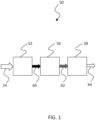
- a compressor system 50 which includes a compressor 52 capable of providing compression to a compressible fluid 54 such as, but not limited to, air.
- a compressible fluid 54 such as, but not limited to, air.
- the compressor 52 can take any variety of forms including but not limited to contact cooled screw compressors. Such contact cooled screw compressors can use any type of lubricant such as but not limited to oil.
- the compressor system 50 can further include one or more devices 56, 58 to remove unwanted content from the flow of compressed air 60 provided by the compressor 52.
- the compressor 52 can be in fluid communication one or more filter(s), air dryer(s), etc such as but not limited to the devices 56 and/or 58 depicted in FIG. 1 .
- the compressor 52 can be coupled with a primary oil filter 56 and a secondary oil filter 58.
- a primary oil filter 56 can be of a centrifugal separator type to remove unwanted oil from the mixed flow of compressed air and oil 60
- the secondary oil filter 56 can be a device that uses a coalescence filter to further remove oil from the flow 62 to produce a cleaner flow 64.
- the coalescence filter 58 might be the only filter used in a compressor system 50, but can still be coupled with further devices for removing unwanted material from the flow of compressed air 60.
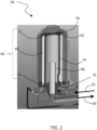
- FIGS. 2 and 3 one example of a filter 58 is depicted which takes the form of a coalescence filter system. It will be appreciated that although the example depicted in FIG. 2 is illustrated using reference numeral 58, some systems may not include the device 56, or may include a device 56 but not of the filtering type. No limitation is hereby intended that the filter 58 must be a secondary filter in any type of system that includes the features of the filter.
- Filter system 58 includes a replaceable filter cartridge 66 having a filter media 68 disposed between a spinner 70 and end cap 72. In accordance with the present invention, the replaceable cartridge 66 is inserted around a mesh filter member 74 which is situated upon a mesh holder 76.
- a housing 78 is used to enclose the filter cartridge 66 and form various flow passages for the conveyance of a mixed flow of compressed fluid and oil as well as a filtered flow.
- the housing 78 can be attached to the base of the unit through a threaded or bayonet type connection, but other connection types are also contemplated. In one form the housing 78 is attached using a quarter-turn.
- a mixed flow of compressed air 62 enters the filter system 58 it travels down a conduit and it turned to flow upward and between the mesh holder 76 and the housing 78.
- air is routed between the mesh holder 76 and the housing 78 is passes through the spinner 70 which imparts a circumferential rotation to the flow 62.
- Suitable space is provided between the filter media 68 and the housing 78 to permit swirling passage of the flow 62 and adequate distribution of the flow 62.
- a circular shaped filter media 68 and inner surface of the housing 78 aid in the swirling motion of air.
- a standpipe 80 can be provided to extend away from the mesh holder 76 and is used to receive the flow of compressed fluid 64 after some or all of oil in the mixed flow 62 has been extracted via the filter media 68 and mesh filter element 74.
- the standpipe 80 can be an integral portion of the mesh holder 76, or can be a separate part that is integrated with the mesh holder 76. The flow received into the standpipe 80 is then directed out of the filter system 58 through a passage.
- the filter cartridge 66 can be made as a replaceable module that can be manipulated/handled as a unitary whole as it is inserted into a filter system 58. It is envisioned that such a modular, stand-alone component can include the filter media 68 and at least one of the spinner 70 and end cap 72. In some forms the stand-alone cartridge 66 can include additional components beyond the filter media and either or both of the spinner 70 and end cap 72.
- the filter media 68 can take on a variety of forms suitable to coalesce oil from the mixed stream 62 of compressed fluid and oil.
- the filter media 68 can be made of paper made using any variety of fiber material.
- the filter media 68 can be made of rolled paper, but other forms are also contemplated such as pleated, etc.
- the spinner 70 includes an inner ring 82, outer ring 84, and airflow members 86 extending between the inner and outer rings.
- the airflow members 86 can take on any variety of forms including vanes, orifices, etc. In the form of vanes the airflow members 86 can extend between respective leading and trailing edges in any variety of manners. For example, the airflow members 86 can extend in a straight line between its leading and trailing edges. In some forms a camber line between the leading and trailing edges can be curved. In certain forms the camber line can be continuous or non-continuous. In still other forms the airflow members 86 can extend in a segmented manner between leading and trailing edges. In short, any variety of shapes are contemplated for the airflow members 86 of the spinner.
- the airflow members 86 can furthermore impart any degree of circumferential motion of fluid flowing therethrough. In some forms the airflow members 86 can impart a relatively higher degree of circumferential motion than axial motion of the fluid, while in other forms the airflow members 86 can impart a relatively higher degree of axial motion than circumferential motion. In still other forms the circumferential and axial components of fluid velocity can be the same.
- one or more airflow passages 88 will be formed in the spinner to traverse from an upstream side of the spinner to a downstream side, As such, the shape of the passages (which can be formed by neighboring vanes, for example) can dictate the degree of circumferential motion relative to the degree of axial motion of the air exiting the downstream side of the spinner 70.
- the spinner 70 in the illustrated example includes both inner ring 82 and outer ring 86
- the spinner 70 can include fewer components.
- the spinner 70 can have the outer ring 84 and airflow members 86, but lack the inner ring 82. In such a form the airflow members 86 can be individually affixed to the filter media.
- the spinner 70 can have the inner ring 82 and airflow members 86 but otherwise lack an outer ring 84.
- the spinner 70 can be attached to the filter media 68 via any suitable manner, whether mechanical, bonding, or otherwise. In some forms the spinner 70 can be attached using chemical bonding such as through an adhesive process such as gluing or epoxying. Epoxy can include can be any of a basic component or cured end products of epoxy resins, as well as represent the epoxide functional group. Any suitable type of adhesive is contemplated.
- the end cap 72 can be used to enclose the open interior of the filter media 68.
- the end cap can include an annular slot defined between an inside wall 88 and outside wall 90 which can be used to receive the filter media 68 and in some examples also receive the mesh filter element 74.
- Either or both of the inside wall 88 and outside wall 90 can extend uninterrupted around the periphery of the filter media 68, but in some forms either or both of the inside wall 88 and outside wall 90 can include a broken configuration.
- the size of the annular slot between the inside wall 88 and outside wall 90 can receive both of the filter media 68 and mesh filter element 74.
- the inside wall 88 can include a chamfer or sloped edge to pilot the mesh filter element 74 when the filter cartridge 66 is inserted onto the mesh filter element 74.
- the housing 78 can include a protuberance 92 which can be used to urge the filter cartridge 66 into a seated position upon the mesh holder 76.
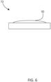
- the protuberance 92 can be located on the end cap 72 as depicted in FIG. 6 .
- the protuberance 92 can take on any suitable form and is generally located within the outer periphery of the end cap 72. Wherever it is located, the protuberance 92 can one or more raised surfaces which are typically blunted in shape as shown.
- the end cap 72 70 can be attached to the filter media 68 via any suitable manner, whether mechanical, bonding, or otherwise.
- the end cap 72 can be attached using chemical bonding such as through an adhesive process such as gluing or epoxying.
- Epoxy can include can be any of a basic component or cured end products of epoxy resins, as well as represent the epoxide functional group. Any suitable type of adhesive is contemplated.
- each of the filter media 68, spinner 70, and end cap 72 can all be different, but in some forms one or more of the materials used for the filter media, spinner, and end cap can be the same.
- the discussion below related to the incineration of the filter media material is also applicable to the material used in the construction of the spinner and end cap.
- the material type of the spinner 70 and/or end cap 72 are different from the filter media material, but it will nevertheless be understood that the description below of waste disposal of the filter media also applies to the spinner 70 and end cap 72 as well.
- the filter media 68 can be made of a filter media material that can be burned, such as through combustion, in a process that can be characterized by a high temperature exothermic redox chemical reaction between a fuel and an oxidant.
- Thermal oxidation of the filter media material can include a combustion process such as deflagration or any other high-temperature exothermic reaction between a fuel and oxidant.
- the filter media 68 can act as the fuel to be thermally oxidized with an oxidant such as but not limited to air. It is contemplated that in some examples the filter media material can be consumed via thermal oxidation and provide a greater thermal energy output as a result of the thermal oxidation than the amount of energy input to provide the elevated temperatures needed for the thermal oxidation to occur.
- any or all of the filter media material, spinner material, and end cap material are made of a material that can be disposed of via incineration in a waste treatment process.
- incineration can convert the components (filter media, spinner, and/or end cap) into ash, flue gas, and heat.
- the material type can provide energy recovery during the incineration process.
- the material type used in some examples of any of the components to be incinerated meets with applicable regulations of material type suitable for incineration, whether those regulations are promulgated by the United States Environmental Protection Agency, among any potential others.
- Various types of incineration processes are contemplated, including burn piles, burn barrels, moving grates, fixed grate, rotary kiln, fluidized bed, and specialized incineration.
- the spinner material is contemplated to be made of plastic, such as but not limited to organic polymers that can be of a thermoplastic or thermosetting type polymer. It is contemplated that the wide range of plastic materials suitable for use as the spinner material can be thermally oxidized in an incineration process as mentioned above anywhere in a temperature range of between about 200°C (390°F) to about 600°C (1100°F) but other ranges may be useful for other plastic-like materials.
- the end cap material is contemplated to be made of rubber or other suitable type of elastomer, such as but not limited to those materials that include polyisoprenes or organic compound isoprenes. It is contemplated that the wide range of rubber materials suitable for use as the end cap material can be thermally oxidized in an incineration process as mentioned above anywhere in a temperature range of between about 250°C (480°F) to about 350°C (662°F) but other ranges may be useful for other rubber-like materials.
- the mesh filter element 74 can take on a variety of forms and be made from a variety of materials.
- the mesh filter element 74 can be a wire mesh construction made of any suitable metallic wire fiber.
- the mesh construction can be woven or non-woven, depending on the application. Such non-woven construction can be made from short and long fibers which can be bonded together using chemical, mechanical, heat, or solvent treatments.
- the non-woven examples can be flat or tufted porous sheets.
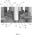
- the mesh holder 76 can include a wide end 94 and a narrow end 96 disposed opposite the wide end 94 which generally takes a frusto-conical shape similar to a truncated cone.
- the mesh holder 76 is coupled with a combo-block 98 which includes a drain line 100 which carries oil away from the mesh holder 76.
- the combo-block 98 can be any suitable device that provides a seat for the mesh holder 76 and that receives collected oil from the mesh holder 76.
- the mesh holder 76 can be coupled to the combo-block 100 via a compression fit via one or more seals such as but not limited to o-rings 102. Further details of the coupling of the mesh holder 76 and combo-block 100 are described further below.
- the mesh holder 76 includes an annular groove 104 defined between an inner wall 106 and outer wall 108.
- the annular groove 104 is structured to receive the mesh filter element 74.
- the outer wall 102 can be sized larger than the inner wall 100 such that oil that collects in the annular groove 104 is discouraged from radially escaping the mesh holder 76 and draining down the side.
- the mesh holder 76 also includes one or more drain lines 110 in fluid communication with the annular groove 104 to carry away oil that has been collected as a result of the filtering.
- Oil collected in the annular groove 104 can flow through drain line 110 to a gallery 112 located between the stand pipe 80 and the mesh holder 76.
- the gallery 112 can be any shape and size and in one form is annular in shape.
- the gallery 112 is in fluid communication with the drain line 100 of the combo-block 98.
- Various seals 114 and 116 can also be used to discourage oil from escaping beyond the drain line 100. Seals 114 and 116 can be o-rings, but other types of seals are also contemplated.
- the filter cartridge 66 can interface with the mesh holder 76 via the spinner 70, although other engagement interfaces are also contemplated.
- the spinner can include a stepped feature to fit upon the outer edge of the mesh holder 76 near the outside wall 90.
- the outside wall 90 includes a complementary stepped feature to receive the spinner 70.
- mesh holder 76, stand-pipe 80, and combo-block 98 are depicted as separate elements that together help support and drain oil away from the filter cartridge 66, in some examples two or more of these components and be made integral with each other.
Landscapes
- Chemical & Material Sciences (AREA)
- Chemical Kinetics & Catalysis (AREA)
- Physics & Mathematics (AREA)
- Geometry (AREA)
- Filtering Of Dispersed Particles In Gases (AREA)
Claims (18)
- Un appareil comprenant :un boîtier de filtre (78) ;un porte-tamis (76) disposé à l'intérieur du boîtier de filtre (78) de telle sorte qu'un passage d'écoulement est défini entre le porte-tamis et le boîtier de filtre ;un élément de filtre à tamis (74) supporté par le porte-tamis (76) ; etune cartouche filtrante remplaçable (66) qui présente un intérieur ouvert et qui est raccordée de manière amovible au porte-tamis (76), la cartouche filtrante remplaçable étant insérée autour de l'élément de filtre à tamis (74), la cartouche filtrante remplaçable présentant un média filtrant (68) qui s'étend dans une direction axiale et est disposé entre une centrifugeuse d'écoulement d'air de forme annulaire (70) et un capuchon d'extrémité (72), et où la centrifugeuse d'écoulement d'air de forme annulaire est fixée à une surface externe du média filtrant de telle sorte que la cartouche filtrante remplaçable est modulaire et peut être manipulée comme un tout unitaire lorsqu'elle est insérée jusque dans le boîtier de filtre (78), la centrifugeuse d'écoulement d'air de forme annulaire incluant une bague interne (82), une bague externe (84), et une pluralité d'éléments d'écoulement d'air (86) s'étendant entre la bague interne et la bague externe, la pluralité d'éléments d'écoulement d'air définissant une pluralité de passages (88), la pluralité d'éléments d'écoulement d'air étant structurés pour conférer une composante de tourbillonnement circonférentielle à un écoulement passant de fluide dans le passage d'écoulement lorsque la cartouche filtrante remplaçable (66) est installée dans le boîtier de filtre (78), l'écoulement de fluide traversant par la suite dans son prolongement le média filtrant (68) et l'élément de filtre à tamis (74) jusqu'à pénétrer dans l'intérieur ouvert de la cartouche filtrante (66).
- L'appareil de la revendication 1, où la centrifugeuse d'écoulement d'air de forme annulaire (70) est liée au média filtrant (68).
- L'appareil de la revendication 1 ou de la revendication 2, où la pluralité d'éléments d'écoulement d'air (86) sont des pales d'écoulement d'air présentant chacune un bord d'attaque et un bord de fuite, chaque passage de la pluralité de passages étant défini par une surface supérieure d'une des pales d'écoulement d'air et une surface inférieure d'une des pales d'écoulement d'air adjacente.
- L'appareil de n'importe quelle revendication précédente, où le matériau de centrifugeuse s'oxyde thermiquement à une température au-dessous de 600 °C (1 100 °F).
- L'appareil de n'importe lesquelles des revendications précédentes, où la centrifugeuse d'écoulement d'air de forme annulaire (70) forme une surface de butée structurée pour se placer contre un boîtier de contenant filtrant, et où la centrifugeuse d'écoulement d'air de forme annulaire est liée par liaison chimique au média filtrant (68).
- L'appareil de n'importe lesquelles des revendications précédentes, où un capuchon d'extrémité (72) est fixé au média filtrant au niveau d'une deuxième extrémité afin de fermer hermétiquement un intérieur ouvert du média filtrant, le capuchon d'extrémité incluant un renfoncement pour recevoir le média filtrant (68), le renfoncement étant suffisamment grand pour accueillir un filtre à tamis complémentaire (76) lorsqu'il est inséré jusque dans l'intérieur ouvert du média filtrant.
- L'appareil de la revendication 6, où le capuchon d'extrémité (72) est lié au média filtrant (68) au niveau de la deuxième extrémité, et où le capuchon d'extrémité inclut une saillie extérieure qui s'étend à partir d'une surface supérieure du capuchon dans une direction qui va en s'éloignant de l'intérieur ouvert, la saillie extérieure étant construite pour s'engager dans le boîtier de filtre.
- L'appareil de la revendication 6, où le média filtrant (68) présente une section transversale circulaire, le média filtrant étant structuré pour retirer du lubrifiant entraîné dans un écoulement de gaz comprimé, le capuchon d'extrémité étant raccordé au niveau d'une première extrémité axiale du média filtrant pour enfermer un intérieur ouvert du média filtrant, le capuchon d'extrémité (72) présentant une rainure formant un arc formée sur une surface intérieure positionnée à l'intérieur du média filtrant, la rainure formant un arc étant définie entre une paroi de rainure interne et une paroi de rainure externe, une distance entre les parois de rainure interne et externe étant dimensionnée pour être à la mesure du média filtrant, le capuchon d'extrémité étant défini par une délimitation périphérique et présentant une saillie émoussée s'étendant à partir d'un intérieur de la délimitation périphérique, la saillie émoussée étant structurée pour se mettre au contact d'une surface interne du boîtier de filtre afin de fournir une pression positive à la cartouche filtrante.
- L'appareil de la revendication 8, où le capuchon d'extrémité (72) inclut une saillie émoussée unique (92) positionnée radialement vers l'intérieur par rapport à une périphérie externe du capuchon d'extrémité.
- L'appareil de la revendication 8 ou de la revendication 9, la saillie émoussée prenant la forme d'une protubérance présentant un point de contact arrondi, et où la saillie émoussée s'étend à partir du centre du capuchon d'extrémité (72).
- L'appareil de n'importe lesquelles des revendications 8 à 10, où le capuchon d'extrémité (72) est lié par liaison chimique au média filtrant, et où le capuchon d'extrémité est réalisé à partir d'un matériau de capuchon d'extrémité présentant une composition qui s'oxydera exothermiquement à des températures élevées.
- L'appareil de n'importe lesquelles des revendications 8 à 11, où la rainure formant un arc est une rainure de forme annulaire, et où le capuchon d'extrémité (72) est lié par liaison chimique au média filtrant.
- L'appareil de la revendication 12, où la distance entre les parois de rainure interne et externe est dimensionnée afin d'accueillir un média filtrant secondaire en plus du média filtrant lié par liaison chimique au capuchon d'extrémité (72).
- L'appareil de n'importe lesquelles des revendications 8 à 13, où la centrifugeuse (70) est fixée à une deuxième extrémité axiale du média filtrant (68) opposée à la première extrémité axiale, où la centrifugeuse est fixée par le biais d'une liaison chimique, et où la cartouche filtrante (66) avec le capuchon d'extrémité (72) et la centrifugeuse (70) sont construits comme un dispositif modulaire capable d'être manipulé comme un tout unitaire lorsque la cartouche filtrante est insérée jusque dans un boîtier de filtre.
- L'appareil de la revendication 14, où le média filtrant (68) est réalisé en un matériau qui entre en combustion à des températures élevées, où le capuchon d'extrémité (72) est réalisé en un matériau qui entre en combustion à des températures élevées, et où la centrifugeuse (70) est réalisée en un matériau qui entre en combustion à des températures élevées.
- Un ensemble de filtre à huile structuré pour retirer de l'huile d'un écoulement mixte d'air comprimé et d'huile, l'ensemble de filtre à huile comprenant :un appareil selon n'importe quelle revendication précédente ; etune base de bloc combiné (98) qui inclut un passage d'huile de bloc combiné pour la réception d'huile retirée de l'écoulement mixte grâce à l'action de l'ensemble de filtre à huile ;où le porte-tamis (76) est un porte-tamis de forme tronconique présentant un intérieur ouvert s'étendant entre une première base de la forme tronconique et une deuxième base opposée de la forme tronconique, le porte-tamis incluant en sus un puits annulaire défini dans une première extrémité (94) du porte-tamis et qui est structuré pour recevoir l'élément de filtre à tamis (74), le porte-tamis incluant en sus au moins un passage d'huile qui s'étend du puits annulaire jusqu'à l'intérieur ouvert ; et l'ensemble de filtre à huile comprenant en sus un tube vertical (80) s'étendant à partir de l'intérieur ouvert et en s'éloignant de la première extrémité.
- L'ensemble de filtre à huile de la revendication 16, où le tube vertical (80) est inséré comme un composant distinct jusque dans l'intérieur ouvert du porte-tamis, où le porte-tamis est couplé à la base de bloc combiné (98) par le biais d'un raccord à compression de joint torique, et où un espace annulaire est formé entre un extérieur du tube vertical et une paroi intérieure du porte-tamis qui définit l'intérieur ouvert, l'espace annulaire étant en communication avec l'au moins un passage d'huile.
- L'ensemble de filtre à huile de la revendication 16 ou de la revendication 17, où le porte-tamis inclut en sus une paroi externe définissant le puits annulaire, la paroi externe s'étendant en s'éloignant de la première extrémité afin de former un barrage structuré pour décourager de l'huile de s'écouler radialement vers l'extérieur en s'éloignant du porte-tamis, et où l'ensemble de filtre à huile inclut en sus un boîtier amovible présentant une surface intérieure structurée pour venir en butée sur un organe de filtre à huile remplaçable placé contre le porte-tamis.
Priority Applications (1)
| Application Number | Priority Date | Filing Date | Title |
|---|---|---|---|
| EP24164121.6A EP4360733A3 (fr) | 2018-12-21 | 2019-12-20 | Système de filtre et cartouche de filtre remplaçable |
Applications Claiming Priority (1)
| Application Number | Priority Date | Filing Date | Title |
|---|---|---|---|
| US16/229,739 US11331610B2 (en) | 2018-12-21 | 2018-12-21 | Filter system and replaceable filter cartridge |
Related Child Applications (1)
| Application Number | Title | Priority Date | Filing Date |
|---|---|---|---|
| EP24164121.6A Division EP4360733A3 (fr) | 2018-12-21 | 2019-12-20 | Système de filtre et cartouche de filtre remplaçable |
Publications (3)
| Publication Number | Publication Date |
|---|---|
| EP3669967A2 EP3669967A2 (fr) | 2020-06-24 |
| EP3669967A3 EP3669967A3 (fr) | 2020-08-26 |
| EP3669967B1 true EP3669967B1 (fr) | 2024-04-03 |
Family
ID=69005415
Family Applications (2)
| Application Number | Title | Priority Date | Filing Date |
|---|---|---|---|
| EP24164121.6A Withdrawn EP4360733A3 (fr) | 2018-12-21 | 2019-12-20 | Système de filtre et cartouche de filtre remplaçable |
| EP19219020.5A Active EP3669967B1 (fr) | 2018-12-21 | 2019-12-20 | Système de filtre et cartouche de filtre remplaçable |
Family Applications Before (1)
| Application Number | Title | Priority Date | Filing Date |
|---|---|---|---|
| EP24164121.6A Withdrawn EP4360733A3 (fr) | 2018-12-21 | 2019-12-20 | Système de filtre et cartouche de filtre remplaçable |
Country Status (3)
| Country | Link |
|---|---|
| US (3) | US11331610B2 (fr) |
| EP (2) | EP4360733A3 (fr) |
| CN (2) | CN111420487A (fr) |
Families Citing this family (3)
| Publication number | Priority date | Publication date | Assignee | Title |
|---|---|---|---|---|
| WO2017092795A1 (fr) * | 2015-12-01 | 2017-06-08 | Ateliers Busch S.A. | Pompe a vide avec element filtrant |
| US12239932B2 (en) * | 2020-10-14 | 2025-03-04 | Purdue Research Foundation | Bernoulli air processing system |
| WO2024099730A1 (fr) * | 2022-11-07 | 2024-05-16 | Altair (UK) Limited | Filtre à impulsions amélioré à support intégral |
Family Cites Families (23)
| Publication number | Priority date | Publication date | Assignee | Title |
|---|---|---|---|---|
| US3036711A (en) | 1959-01-06 | 1962-05-29 | Purolator Products Inc | Filter unit |
| US4035306A (en) | 1975-06-23 | 1977-07-12 | Sheller-Globe Corporation | Removable cartridge filter |
| DE8501736U1 (de) * | 1985-01-24 | 1985-08-22 | Filterwerk Mann & Hummel Gmbh, 7140 Ludwigsburg | Vorrichtung zum Abscheiden von Öltröpfchen aus Luft |
| US5028318A (en) | 1989-04-19 | 1991-07-02 | Aeroquip Corporation | Cyclonic system for separating debris particles from fluids |
| US5066391A (en) | 1990-08-22 | 1991-11-19 | Faria Manuel S | Reusable liquid filter assembly |
| US5170640A (en) | 1991-03-04 | 1992-12-15 | Carrier Corporation | Oil separator |
| US6004366A (en) * | 1994-11-23 | 1999-12-21 | Donaldson Company, Inc. | Reverse flow air filter arrangement and method |
| US5548893A (en) | 1995-03-20 | 1996-08-27 | Koelfgen; Douglas F. | Spin-on oil filter replacement element |
| DE19634720A1 (de) * | 1996-08-28 | 1998-03-05 | Mann & Hummel Filter | Filterpatrone |
| US6099606A (en) * | 1998-03-19 | 2000-08-08 | Donaldson Company, Inc. | Air filtration arrangements having spacer constructions |
| DE19908377A1 (de) | 1999-02-26 | 2000-08-31 | Schlafhorst & Co W | Filtereinrichtung für eine Kreuzspulen herstellende Textilmaschine |
| DE10233012A1 (de) * | 2002-07-20 | 2004-02-05 | Mann + Hummel Gmbh | Abscheider zur Reinigung eines Fluidstromes |
| WO2004094831A1 (fr) * | 2003-04-16 | 2004-11-04 | Dow Global Technologies Inc. | Systeme pour purifier un liquide lubrifiant et surveiller son etat dans des compresseurs et autres equipements |
| US7326266B2 (en) | 2003-10-31 | 2008-02-05 | Flair Corporation | Coalescing type filter apparatus and method |
| GB0417458D0 (en) | 2004-08-05 | 2004-09-08 | Domnick Hunter Ltd | Filter assembly |
| WO2007053411A2 (fr) * | 2005-10-28 | 2007-05-10 | Donaldson Company, Inc. | Séparateur d'aérosols ; composants ; et procédés |
| DE202006019003U1 (de) * | 2006-12-14 | 2008-05-21 | Mann + Hummel Gmbh | Flüssigkeitsabscheider, insbesondere Ölabscheider für Druckluftanlagen |
| DE102008046499A1 (de) * | 2008-09-09 | 2010-03-18 | Mann + Hummel Gmbh | Filter mit Drainageanschluss |
| DE102011108061A1 (de) | 2011-07-21 | 2013-01-24 | Mann + Hummel Gmbh | Fluidfilteranordnung und Filterverfahren |
| US20150059304A1 (en) * | 2013-09-02 | 2015-03-05 | Mann+Hummel Gmbh | Filter Element and Filter System with a Filter Element |
| DE102013015052B4 (de) * | 2013-09-12 | 2015-10-15 | Mann + Hummel Gmbh | Zyklon-Filtereinrichtung |
| DE102016006095B4 (de) | 2015-07-16 | 2023-05-25 | Mann+Hummel Gmbh | Abscheidemodul, Leitungsmodul sowie Entlüftungsvorrichtung |
| DE102015011225A1 (de) | 2015-08-27 | 2017-03-02 | Rt-Filtertechnik Gmbh | Abscheidevorrichtung |
-
2018
- 2018-12-21 US US16/229,739 patent/US11331610B2/en active Active
-
2019
- 2019-12-20 EP EP24164121.6A patent/EP4360733A3/fr not_active Withdrawn
- 2019-12-20 EP EP19219020.5A patent/EP3669967B1/fr active Active
- 2019-12-20 CN CN201911329027.4A patent/CN111420487A/zh active Pending
- 2019-12-20 CN CN202210604128.3A patent/CN114797325A/zh active Pending
-
2022
- 2022-03-21 US US17/699,556 patent/US11865481B2/en active Active
-
2023
- 2023-11-30 US US18/524,410 patent/US12134054B2/en active Active
Also Published As
| Publication number | Publication date |
|---|---|
| EP4360733A2 (fr) | 2024-05-01 |
| EP3669967A3 (fr) | 2020-08-26 |
| EP3669967A2 (fr) | 2020-06-24 |
| US12134054B2 (en) | 2024-11-05 |
| US11331610B2 (en) | 2022-05-17 |
| US20220280893A1 (en) | 2022-09-08 |
| US11865481B2 (en) | 2024-01-09 |
| US20240165550A1 (en) | 2024-05-23 |
| CN114797325A (zh) | 2022-07-29 |
| CN111420487A (zh) | 2020-07-17 |
| EP4360733A3 (fr) | 2024-05-22 |
| US20200197849A1 (en) | 2020-06-25 |
Similar Documents
| Publication | Publication Date | Title |
|---|---|---|
| US12134054B2 (en) | Filter system and replaceable filter cartridge | |
| EP1996309B1 (fr) | Filtre avec etui asseche | |
| EP3826750B1 (fr) | Joint radial pour filtre du type à montage par vissage | |
| CN101815570B (zh) | 带有锯齿形密封件的过滤器元件 | |
| EP2451551B1 (fr) | Filtration en deux étapes impliquant une barrière pour séparation carburant/eau | |
| CA1314500C (fr) | Contenant de fluide | |
| RU2700058C2 (ru) | Перепускная крышка и способ направления текучей среды через фильтр | |
| EP2755740B1 (fr) | Panier de support de filtre amélioré | |
| US20120292243A1 (en) | Filter arrangments and filter apparatuses which include filter arrangements | |
| US20200122074A1 (en) | Methods, apparatus and products for filtering | |
| EP2949374B1 (fr) | Procédés et éléments de filtre pour filtrer des fluides | |
| US20240058734A1 (en) | Filter assemblies with combined axial and radial sealing | |
| US9566543B2 (en) | Sealing arrangement for apparatus for filtering, and methods, and products for filtering | |
| CN102536462A (zh) | 用于涡轮系统的过滤器组件 | |
| CA2285288A1 (fr) | Cartouche filtre et ensemble filtre | |
| CN110248714B (zh) | 适用于无螺纹外壳的可扩展螺纹适配器 | |
| CN107407239A (zh) | 包括预过滤元件和主过滤元件并且包括水分离单元的燃料过滤器和燃料过滤器插入件 | |
| EP3415217B1 (fr) | Filtre avec connecteur pour joindre des sections de filtre plissé | |
| US20240335772A1 (en) | Filter cartridge with expandable endplate seal | |
| CN222677383U (zh) | 过滤系统和过滤器头 | |
| CN119013088A (zh) | 具有浮动密封接口的过滤器组件 | |
| CN119095658A (zh) | 具有改进的立管设计的过滤系统 | |
| KR20120130287A (ko) | 필터 배열 및 필터 배열을 포함하는 필터 장치 | |
| HK1160812A1 (en) | Fluid filter with nutplate having an end face seal and outer attachment design |
Legal Events
| Date | Code | Title | Description |
|---|---|---|---|
| PUAI | Public reference made under article 153(3) epc to a published international application that has entered the european phase |
Free format text: ORIGINAL CODE: 0009012 |
|
| STAA | Information on the status of an ep patent application or granted ep patent |
Free format text: STATUS: THE APPLICATION HAS BEEN PUBLISHED |
|
| AK | Designated contracting states |
Kind code of ref document: A2 Designated state(s): AL AT BE BG CH CY CZ DE DK EE ES FI FR GB GR HR HU IE IS IT LI LT LU LV MC MK MT NL NO PL PT RO RS SE SI SK SM TR |
|
| AX | Request for extension of the european patent |
Extension state: BA ME |
|
| PUAL | Search report despatched |
Free format text: ORIGINAL CODE: 0009013 |
|
| AK | Designated contracting states |
Kind code of ref document: A3 Designated state(s): AL AT BE BG CH CY CZ DE DK EE ES FI FR GB GR HR HU IE IS IT LI LT LU LV MC MK MT NL NO PL PT RO RS SE SI SK SM TR |
|
| AX | Request for extension of the european patent |
Extension state: BA ME |
|
| RIC1 | Information provided on ipc code assigned before grant |
Ipc: B01D 46/00 20060101AFI20200720BHEP Ipc: B01D 46/24 20060101ALI20200720BHEP |
|
| STAA | Information on the status of an ep patent application or granted ep patent |
Free format text: STATUS: REQUEST FOR EXAMINATION WAS MADE |
|
| 17P | Request for examination filed |
Effective date: 20210225 |
|
| RBV | Designated contracting states (corrected) |
Designated state(s): AL AT BE BG CH CY CZ DE DK EE ES FI FR GB GR HR HU IE IS IT LI LT LU LV MC MK MT NL NO PL PT RO RS SE SI SK SM TR |
|
| RAP1 | Party data changed (applicant data changed or rights of an application transferred) |
Owner name: INGERSOLL-RAND INDUSTRIAL U.S., INC. |
|
| STAA | Information on the status of an ep patent application or granted ep patent |
Free format text: STATUS: EXAMINATION IS IN PROGRESS |
|
| 17Q | First examination report despatched |
Effective date: 20210707 |
|
| GRAP | Despatch of communication of intention to grant a patent |
Free format text: ORIGINAL CODE: EPIDOSNIGR1 |
|
| STAA | Information on the status of an ep patent application or granted ep patent |
Free format text: STATUS: GRANT OF PATENT IS INTENDED |
|
| INTG | Intention to grant announced |
Effective date: 20231109 |
|
| GRAS | Grant fee paid |
Free format text: ORIGINAL CODE: EPIDOSNIGR3 |
|
| GRAA | (expected) grant |
Free format text: ORIGINAL CODE: 0009210 |
|
| STAA | Information on the status of an ep patent application or granted ep patent |
Free format text: STATUS: THE PATENT HAS BEEN GRANTED |
|
| AK | Designated contracting states |
Kind code of ref document: B1 Designated state(s): AL AT BE BG CH CY CZ DE DK EE ES FI FR GB GR HR HU IE IS IT LI LT LU LV MC MK MT NL NO PL PT RO RS SE SI SK SM TR |
|
| REG | Reference to a national code |
Ref country code: CH Ref legal event code: EP |
|
| REG | Reference to a national code |
Ref country code: IE Ref legal event code: FG4D |
|
| REG | Reference to a national code |
Ref country code: DE Ref legal event code: R096 Ref document number: 602019049387 Country of ref document: DE |
|
| REG | Reference to a national code |
Ref country code: LT Ref legal event code: MG9D |
|
| RAP4 | Party data changed (patent owner data changed or rights of a patent transferred) |
Owner name: INGERSOLL-RAND INDUSTRIAL U.S., INC. |
|
| REG | Reference to a national code |
Ref country code: NL Ref legal event code: MP Effective date: 20240403 |
|
| REG | Reference to a national code |
Ref country code: AT Ref legal event code: MK05 Ref document number: 1671637 Country of ref document: AT Kind code of ref document: T Effective date: 20240403 |
|
| PG25 | Lapsed in a contracting state [announced via postgrant information from national office to epo] |
Ref country code: NL Free format text: LAPSE BECAUSE OF FAILURE TO SUBMIT A TRANSLATION OF THE DESCRIPTION OR TO PAY THE FEE WITHIN THE PRESCRIBED TIME-LIMIT Effective date: 20240403 |
|
| PG25 | Lapsed in a contracting state [announced via postgrant information from national office to epo] |
Ref country code: NL Free format text: LAPSE BECAUSE OF FAILURE TO SUBMIT A TRANSLATION OF THE DESCRIPTION OR TO PAY THE FEE WITHIN THE PRESCRIBED TIME-LIMIT Effective date: 20240403 |
|
| PG25 | Lapsed in a contracting state [announced via postgrant information from national office to epo] |
Ref country code: IS Free format text: LAPSE BECAUSE OF FAILURE TO SUBMIT A TRANSLATION OF THE DESCRIPTION OR TO PAY THE FEE WITHIN THE PRESCRIBED TIME-LIMIT Effective date: 20240803 |
|
| PG25 | Lapsed in a contracting state [announced via postgrant information from national office to epo] |
Ref country code: BG Free format text: LAPSE BECAUSE OF FAILURE TO SUBMIT A TRANSLATION OF THE DESCRIPTION OR TO PAY THE FEE WITHIN THE PRESCRIBED TIME-LIMIT Effective date: 20240403 |
|
| PG25 | Lapsed in a contracting state [announced via postgrant information from national office to epo] |
Ref country code: HR Free format text: LAPSE BECAUSE OF FAILURE TO SUBMIT A TRANSLATION OF THE DESCRIPTION OR TO PAY THE FEE WITHIN THE PRESCRIBED TIME-LIMIT Effective date: 20240403 Ref country code: FI Free format text: LAPSE BECAUSE OF FAILURE TO SUBMIT A TRANSLATION OF THE DESCRIPTION OR TO PAY THE FEE WITHIN THE PRESCRIBED TIME-LIMIT Effective date: 20240403 |
|
| PG25 | Lapsed in a contracting state [announced via postgrant information from national office to epo] |
Ref country code: GR Free format text: LAPSE BECAUSE OF FAILURE TO SUBMIT A TRANSLATION OF THE DESCRIPTION OR TO PAY THE FEE WITHIN THE PRESCRIBED TIME-LIMIT Effective date: 20240704 |
|
| PG25 | Lapsed in a contracting state [announced via postgrant information from national office to epo] |
Ref country code: PT Free format text: LAPSE BECAUSE OF FAILURE TO SUBMIT A TRANSLATION OF THE DESCRIPTION OR TO PAY THE FEE WITHIN THE PRESCRIBED TIME-LIMIT Effective date: 20240805 |
|
| PG25 | Lapsed in a contracting state [announced via postgrant information from national office to epo] |
Ref country code: ES Free format text: LAPSE BECAUSE OF FAILURE TO SUBMIT A TRANSLATION OF THE DESCRIPTION OR TO PAY THE FEE WITHIN THE PRESCRIBED TIME-LIMIT Effective date: 20240403 |
|
| PG25 | Lapsed in a contracting state [announced via postgrant information from national office to epo] |
Ref country code: CZ Free format text: LAPSE BECAUSE OF FAILURE TO SUBMIT A TRANSLATION OF THE DESCRIPTION OR TO PAY THE FEE WITHIN THE PRESCRIBED TIME-LIMIT Effective date: 20240403 |
|
| PG25 | Lapsed in a contracting state [announced via postgrant information from national office to epo] |
Ref country code: AT Free format text: LAPSE BECAUSE OF FAILURE TO SUBMIT A TRANSLATION OF THE DESCRIPTION OR TO PAY THE FEE WITHIN THE PRESCRIBED TIME-LIMIT Effective date: 20240403 |
|
| PG25 | Lapsed in a contracting state [announced via postgrant information from national office to epo] |
Ref country code: PL Free format text: LAPSE BECAUSE OF FAILURE TO SUBMIT A TRANSLATION OF THE DESCRIPTION OR TO PAY THE FEE WITHIN THE PRESCRIBED TIME-LIMIT Effective date: 20240403 |
|
| PG25 | Lapsed in a contracting state [announced via postgrant information from national office to epo] |
Ref country code: LV Free format text: LAPSE BECAUSE OF FAILURE TO SUBMIT A TRANSLATION OF THE DESCRIPTION OR TO PAY THE FEE WITHIN THE PRESCRIBED TIME-LIMIT Effective date: 20240403 |
|
| PG25 | Lapsed in a contracting state [announced via postgrant information from national office to epo] |
Ref country code: PT Free format text: LAPSE BECAUSE OF FAILURE TO SUBMIT A TRANSLATION OF THE DESCRIPTION OR TO PAY THE FEE WITHIN THE PRESCRIBED TIME-LIMIT Effective date: 20240805 Ref country code: PL Free format text: LAPSE BECAUSE OF FAILURE TO SUBMIT A TRANSLATION OF THE DESCRIPTION OR TO PAY THE FEE WITHIN THE PRESCRIBED TIME-LIMIT Effective date: 20240403 Ref country code: NO Free format text: LAPSE BECAUSE OF FAILURE TO SUBMIT A TRANSLATION OF THE DESCRIPTION OR TO PAY THE FEE WITHIN THE PRESCRIBED TIME-LIMIT Effective date: 20240703 Ref country code: LV Free format text: LAPSE BECAUSE OF FAILURE TO SUBMIT A TRANSLATION OF THE DESCRIPTION OR TO PAY THE FEE WITHIN THE PRESCRIBED TIME-LIMIT Effective date: 20240403 Ref country code: IS Free format text: LAPSE BECAUSE OF FAILURE TO SUBMIT A TRANSLATION OF THE DESCRIPTION OR TO PAY THE FEE WITHIN THE PRESCRIBED TIME-LIMIT Effective date: 20240803 Ref country code: HR Free format text: LAPSE BECAUSE OF FAILURE TO SUBMIT A TRANSLATION OF THE DESCRIPTION OR TO PAY THE FEE WITHIN THE PRESCRIBED TIME-LIMIT Effective date: 20240403 Ref country code: GR Free format text: LAPSE BECAUSE OF FAILURE TO SUBMIT A TRANSLATION OF THE DESCRIPTION OR TO PAY THE FEE WITHIN THE PRESCRIBED TIME-LIMIT Effective date: 20240704 Ref country code: FI Free format text: LAPSE BECAUSE OF FAILURE TO SUBMIT A TRANSLATION OF THE DESCRIPTION OR TO PAY THE FEE WITHIN THE PRESCRIBED TIME-LIMIT Effective date: 20240403 Ref country code: ES Free format text: LAPSE BECAUSE OF FAILURE TO SUBMIT A TRANSLATION OF THE DESCRIPTION OR TO PAY THE FEE WITHIN THE PRESCRIBED TIME-LIMIT Effective date: 20240403 Ref country code: CZ Free format text: LAPSE BECAUSE OF FAILURE TO SUBMIT A TRANSLATION OF THE DESCRIPTION OR TO PAY THE FEE WITHIN THE PRESCRIBED TIME-LIMIT Effective date: 20240403 Ref country code: BG Free format text: LAPSE BECAUSE OF FAILURE TO SUBMIT A TRANSLATION OF THE DESCRIPTION OR TO PAY THE FEE WITHIN THE PRESCRIBED TIME-LIMIT Effective date: 20240403 Ref country code: AT Free format text: LAPSE BECAUSE OF FAILURE TO SUBMIT A TRANSLATION OF THE DESCRIPTION OR TO PAY THE FEE WITHIN THE PRESCRIBED TIME-LIMIT Effective date: 20240403 Ref country code: RS Free format text: LAPSE BECAUSE OF FAILURE TO SUBMIT A TRANSLATION OF THE DESCRIPTION OR TO PAY THE FEE WITHIN THE PRESCRIBED TIME-LIMIT Effective date: 20240703 |
|
| REG | Reference to a national code |
Ref country code: DE Ref legal event code: R097 Ref document number: 602019049387 Country of ref document: DE |
|
| PG25 | Lapsed in a contracting state [announced via postgrant information from national office to epo] |
Ref country code: DK Free format text: LAPSE BECAUSE OF FAILURE TO SUBMIT A TRANSLATION OF THE DESCRIPTION OR TO PAY THE FEE WITHIN THE PRESCRIBED TIME-LIMIT Effective date: 20240403 |
|
| PG25 | Lapsed in a contracting state [announced via postgrant information from national office to epo] |
Ref country code: EE Free format text: LAPSE BECAUSE OF FAILURE TO SUBMIT A TRANSLATION OF THE DESCRIPTION OR TO PAY THE FEE WITHIN THE PRESCRIBED TIME-LIMIT Effective date: 20240403 |
|
| PG25 | Lapsed in a contracting state [announced via postgrant information from national office to epo] |
Ref country code: SK Free format text: LAPSE BECAUSE OF FAILURE TO SUBMIT A TRANSLATION OF THE DESCRIPTION OR TO PAY THE FEE WITHIN THE PRESCRIBED TIME-LIMIT Effective date: 20240403 Ref country code: RO Free format text: LAPSE BECAUSE OF FAILURE TO SUBMIT A TRANSLATION OF THE DESCRIPTION OR TO PAY THE FEE WITHIN THE PRESCRIBED TIME-LIMIT Effective date: 20240403 |
|
| PG25 | Lapsed in a contracting state [announced via postgrant information from national office to epo] |
Ref country code: SM Free format text: LAPSE BECAUSE OF FAILURE TO SUBMIT A TRANSLATION OF THE DESCRIPTION OR TO PAY THE FEE WITHIN THE PRESCRIBED TIME-LIMIT Effective date: 20240403 |
|
| PG25 | Lapsed in a contracting state [announced via postgrant information from national office to epo] |
Ref country code: SM Free format text: LAPSE BECAUSE OF FAILURE TO SUBMIT A TRANSLATION OF THE DESCRIPTION OR TO PAY THE FEE WITHIN THE PRESCRIBED TIME-LIMIT Effective date: 20240403 Ref country code: SK Free format text: LAPSE BECAUSE OF FAILURE TO SUBMIT A TRANSLATION OF THE DESCRIPTION OR TO PAY THE FEE WITHIN THE PRESCRIBED TIME-LIMIT Effective date: 20240403 Ref country code: RO Free format text: LAPSE BECAUSE OF FAILURE TO SUBMIT A TRANSLATION OF THE DESCRIPTION OR TO PAY THE FEE WITHIN THE PRESCRIBED TIME-LIMIT Effective date: 20240403 Ref country code: EE Free format text: LAPSE BECAUSE OF FAILURE TO SUBMIT A TRANSLATION OF THE DESCRIPTION OR TO PAY THE FEE WITHIN THE PRESCRIBED TIME-LIMIT Effective date: 20240403 Ref country code: DK Free format text: LAPSE BECAUSE OF FAILURE TO SUBMIT A TRANSLATION OF THE DESCRIPTION OR TO PAY THE FEE WITHIN THE PRESCRIBED TIME-LIMIT Effective date: 20240403 |
|
| PLBE | No opposition filed within time limit |
Free format text: ORIGINAL CODE: 0009261 |
|
| STAA | Information on the status of an ep patent application or granted ep patent |
Free format text: STATUS: NO OPPOSITION FILED WITHIN TIME LIMIT |
|
| 26N | No opposition filed |
Effective date: 20250106 |
|
| PG25 | Lapsed in a contracting state [announced via postgrant information from national office to epo] |
Ref country code: SI Free format text: LAPSE BECAUSE OF FAILURE TO SUBMIT A TRANSLATION OF THE DESCRIPTION OR TO PAY THE FEE WITHIN THE PRESCRIBED TIME-LIMIT Effective date: 20240403 |
|
| PG25 | Lapsed in a contracting state [announced via postgrant information from national office to epo] |
Ref country code: MC Free format text: LAPSE BECAUSE OF FAILURE TO SUBMIT A TRANSLATION OF THE DESCRIPTION OR TO PAY THE FEE WITHIN THE PRESCRIBED TIME-LIMIT Effective date: 20240403 |
|
| REG | Reference to a national code |
Ref country code: CH Ref legal event code: PL |
|
| PG25 | Lapsed in a contracting state [announced via postgrant information from national office to epo] |
Ref country code: LU Free format text: LAPSE BECAUSE OF NON-PAYMENT OF DUE FEES Effective date: 20241220 |
|
| PG25 | Lapsed in a contracting state [announced via postgrant information from national office to epo] |
Ref country code: SE Free format text: LAPSE BECAUSE OF FAILURE TO SUBMIT A TRANSLATION OF THE DESCRIPTION OR TO PAY THE FEE WITHIN THE PRESCRIBED TIME-LIMIT Effective date: 20240403 |
|
| REG | Reference to a national code |
Ref country code: BE Ref legal event code: MM Effective date: 20241231 |
|
| PG25 | Lapsed in a contracting state [announced via postgrant information from national office to epo] |
Ref country code: BE Free format text: LAPSE BECAUSE OF NON-PAYMENT OF DUE FEES Effective date: 20241231 |
|
| PG25 | Lapsed in a contracting state [announced via postgrant information from national office to epo] |
Ref country code: CH Free format text: LAPSE BECAUSE OF NON-PAYMENT OF DUE FEES Effective date: 20241231 |
|
| PG25 | Lapsed in a contracting state [announced via postgrant information from national office to epo] |
Ref country code: IE Free format text: LAPSE BECAUSE OF NON-PAYMENT OF DUE FEES Effective date: 20241220 |
|
| PGFP | Annual fee paid to national office [announced via postgrant information from national office to epo] |
Ref country code: GB Payment date: 20251231 Year of fee payment: 7 |
|
| PG25 | Lapsed in a contracting state [announced via postgrant information from national office to epo] |
Ref country code: IT Free format text: LAPSE BECAUSE OF NON-PAYMENT OF DUE FEES Effective date: 20241220 |
|
| PGFP | Annual fee paid to national office [announced via postgrant information from national office to epo] |
Ref country code: FR Payment date: 20251229 Year of fee payment: 7 |
|
| PGFP | Annual fee paid to national office [announced via postgrant information from national office to epo] |
Ref country code: DE Payment date: 20251230 Year of fee payment: 7 |
|
| PG25 | Lapsed in a contracting state [announced via postgrant information from national office to epo] |
Ref country code: IT Free format text: LAPSE BECAUSE OF NON-PAYMENT OF DUE FEES Effective date: 20241220 |
|
| PGFP | Annual fee paid to national office [announced via postgrant information from national office to epo] |
Ref country code: IT Payment date: 20251229 Year of fee payment: 7 |
|
| PGRI | Patent reinstated in contracting state [announced from national office to epo] |
Ref country code: IT Effective date: 20250430 |