EP1996309B1 - Filtre avec etui asseche - Google Patents
Filtre avec etui asseche Download PDFInfo
- Publication number
- EP1996309B1 EP1996309B1 EP07750687.1A EP07750687A EP1996309B1 EP 1996309 B1 EP1996309 B1 EP 1996309B1 EP 07750687 A EP07750687 A EP 07750687A EP 1996309 B1 EP1996309 B1 EP 1996309B1
- Authority
- EP
- European Patent Office
- Prior art keywords
- filter
- sleeve
- jacket
- seal
- filter element
- Prior art date
- Legal status (The legal status is an assumption and is not a legal conclusion. Google has not performed a legal analysis and makes no representation as to the accuracy of the status listed.)
- Active
Links
Images


Classifications
-
- B—PERFORMING OPERATIONS; TRANSPORTING
- B01—PHYSICAL OR CHEMICAL PROCESSES OR APPARATUS IN GENERAL
- B01D—SEPARATION
- B01D46/00—Filters or filtering processes specially modified for separating dispersed particles from gases or vapours
- B01D46/52—Particle separators, e.g. dust precipitators, using filters embodying folded corrugated or wound sheet material
- B01D46/521—Particle separators, e.g. dust precipitators, using filters embodying folded corrugated or wound sheet material using folded, pleated material
- B01D46/525—Particle separators, e.g. dust precipitators, using filters embodying folded corrugated or wound sheet material using folded, pleated material which comprises flutes
- B01D46/527—Particle separators, e.g. dust precipitators, using filters embodying folded corrugated or wound sheet material using folded, pleated material which comprises flutes in wound arrangement
-
- B—PERFORMING OPERATIONS; TRANSPORTING
- B01—PHYSICAL OR CHEMICAL PROCESSES OR APPARATUS IN GENERAL
- B01D—SEPARATION
- B01D46/00—Filters or filtering processes specially modified for separating dispersed particles from gases or vapours
- B01D46/0002—Casings; Housings; Frame constructions
- B01D46/0004—Details of removable closures, lids, caps or filter heads
-
- B—PERFORMING OPERATIONS; TRANSPORTING
- B01—PHYSICAL OR CHEMICAL PROCESSES OR APPARATUS IN GENERAL
- B01D—SEPARATION
- B01D46/00—Filters or filtering processes specially modified for separating dispersed particles from gases or vapours
- B01D46/0002—Casings; Housings; Frame constructions
- B01D46/0005—Mounting of filtering elements within casings, housings or frames
-
- B—PERFORMING OPERATIONS; TRANSPORTING
- B01—PHYSICAL OR CHEMICAL PROCESSES OR APPARATUS IN GENERAL
- B01D—SEPARATION
- B01D2271/00—Sealings for filters specially adapted for separating dispersed particles from gases or vapours
- B01D2271/02—Gaskets, sealings
-
- Y—GENERAL TAGGING OF NEW TECHNOLOGICAL DEVELOPMENTS; GENERAL TAGGING OF CROSS-SECTIONAL TECHNOLOGIES SPANNING OVER SEVERAL SECTIONS OF THE IPC; TECHNICAL SUBJECTS COVERED BY FORMER USPC CROSS-REFERENCE ART COLLECTIONS [XRACs] AND DIGESTS
- Y10—TECHNICAL SUBJECTS COVERED BY FORMER USPC
- Y10T—TECHNICAL SUBJECTS COVERED BY FORMER US CLASSIFICATION
- Y10T442/00—Fabric [woven, knitted, or nonwoven textile or cloth, etc.]
- Y10T442/10—Scrim [e.g., open net or mesh, gauze, loose or open weave or knit, etc.]
- Y10T442/102—Woven scrim
- Y10T442/159—Including a nonwoven fabric which is not a scrim
- Y10T442/16—Two or more nonwoven layers
Definitions
- This invention generally relates to filter elements and, more particularly, to the jackets and/or seals of such filter elements.
- Gas streams often carry particulate material therein.
- air intake streams to engines for motorized vehicles or power generation equipment, gas streams directed to gas turbines, and air streams to various combustion furnaces often include particulate material therein.
- the particulate material should it reach the internal workings of the various mechanisms involved, can cause damage thereto. It is therefore preferred, for such systems, to remove the particulate material from the gas flow upstream of the engine, turbine, furnace or other equipment involved.
- a variety of air filter or gas filter arrangements have been developed for particulate removal.
- Conventional filter elements will typically employ either a pleated filter media, a depth filter media, or a fluted filter media.
- FIG. 1 Various examples of filter elements employing a fluted filter media are illustrated in U.S. Pat. No. 6,190,432 to Gieseke, et al. , U.S. Pat. No. 5,820,646 to Gillingham, et al. , U.S. Patent No. 3,025,963 to Bauer , and U.S. Pat. No. 4,589,983 to Wydevan .
- the '646 and '983 patents illustrate, for example, filter elements with an integrally formed impervious outer skin with axial flow therethrough.
- WO 00/50152 discloses an air cleaner comprising a fluted filter media and an internal seal as well as moisture release aperture.
- filter elements will typically incorporate a form of an external seal that is adapted to seal the filter element against a housing, mounting base or duct, into which the filter is mounted.
- a foamed urethane seal to provide an external seal. Improvements to such seal arrangements are also disclosed herein.
- a filter element comprises a filter jacket with a moisture release aperture, a fluted filter media, and an internal seal.
- the filter jacket defines a filter jacket inner surface, an upstream end, and a downstream end.
- the moisture release aperture is formed through the outer annular and axially extending wall of the jacket to provide a means for excess water or other fluid to escape.
- the fluted filter media resides within the filter jacket and defines a filter media outer surface.
- the fluted filter media comprises a plurality of flutes where some of the flutes are closed proximate the upstream end and some of the flutes are closed proximate the downstream end.
- the internal seal is formed between the filter jacket inner surface and the filter media outer surface to prevent short circuiting of unfiltered fluid.
- the moisture release aperture is located upstream of the internal seal.
- One preferred version of a filter element comprises:
- the filter jacket further comprises a hood aligned with the moisture release aperture, the hood protectively covering the moisture release aperture.
- the hood comprises flanges and a cover, the flanges projecting radially outwardly from the filter jacket, the cover spaced radially outwardly from the filter jacket and coupled to the flanges.
- the filter jacket further comprises a first sleeve and a second sleeve, the first sleeve and the second sleeve coupled together to form the jacket, a material of the internal seal being located at an interface between the first and second sleeves to bond the first and second sleeves together, the first sleeve and the second sleeve being aligned angularly with an alignment notch and an alignment rib on the first sleeve and the second sleeve, respectively or vice versa.
- the alignment rib projects only partially into the alignment notch leaving an open gap which forms the moisture release aperture.
- the filter jacket further comprises a first sleeve and a second sleeve, the first sleeve and the second sleeve coupled together to form the jacket, a material of the internal seal being located at an interface between the first and second sleeves to bond the first and second sleeves together, wherein the first sleeve is disposed proximate the inlet end and the second sleeve is disposed proximate the outlet end, the moisture release aperture being formed in the first sleeve.
- the filter jacket is fluid pervious upstream of the seal through the moisture release aperture and fluid impervious downstream of the seal.
- the filter element further comprises an external seal mounted to the filter jacket proximate the downstream end.
- annular seal support member extends from the filter jacket proximate the downstream end and includes a plurality of circumferentially spaced perforations, the perforations adapted to receive and secure a seal-forming material employed to form the external seal.
- the filter jacket is formed from a first sleeve having an insertion end and a second sleeve having an outwardly flared receptacle portion, the insertion end telescopically received within the outwardly flared portion.
- the filter jacket is formed from plastic and defines means for gravitationally locating the moisture release aperture proximate a gravitational bottom of the filter jacket inner surface.
- the filter jacket includes an axially-extending annular wall and a discontinuous flange extending outwardly from the annular wall proximate the downstream end, the sealing flange defining one or more intermittent gaps, an outer seal engaging the sealing flange and at least partially projecting through the one or more intermittent gaps.
- the filter jacket includes a baffle proximate the downstream end, the baffle projecting radially inwardly from proximate the filter jacket inner surface toward the downstream end, the baffle facing a free rise surface of a seal-forming material and having a baffle surface arranged to direct a flow of the free rise surface of the seal-forming material surface.
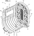
- a filter element 10 that can be used to, for example, filter air entering an engine is illustrated.
- This filter element 10 is adapted to be installed inline between upstream and downstream ducts, thus forming an intermediate section of the duct between upstream and downstream sections.
- the present invention may also be utilized or otherwise incorporated into filters which may be installed and contained in filter housings.
- the filter element 10 comprises a filter jacket 12.
- the filter jacket 12 provides the support structure for the filter element 10 and associated structures for mounting the filter element.
- the jacket 12 preferably includes a moisture release aperture 14 to provide for drainage, as to be discussed in further detail below.
- the filter element 10 also includes a suitable filter media pack which may take the form of fluted filter media 16 (or other appropriate type of media such as those described above), an internal seal 18 formed between the jacket and the filter media, and an external seal 20.
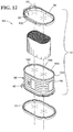
- the filter jacket 12 generally comprises an axially-extending annular wall 21 defining a filter jacket inner surface 22, a filter jacket outer surface 24, a gravitational bottom 26, an upstream end 28, and a downstream end 30. While the filter jacket 12 can be formed from a variety of materials, the jacket is preferably molded from relatively rigid supportive plastic material. While the jacket 12 may be formed of a single component, preferably the jacket is constructed from multiple component pieces fit together such as a first sleeve 94 and a second sleeve 96 as shown in FIG. 12 .
- Each sleeve 94 includes an annular wall portion which collectively form the overall annular wall 21 of the filter jacket 12.
- the filter jacket is fluid impervious downstream of the internal seal 18 and fluid permeable upstream of the internal seal by virtue of the moisture release aperture 14.
- the filter jacket 12 is pervious by virtue of the moisture release aperture 14, while at the same time preventing unfiltered contaminated air from reaching the clean side outlet.
- the filter jacket 12 is illustrated as generally oval in shape when viewed from either the upstream end 30 or downstream end 32, the filter jacket is capable of having a variety of different configurations, depending upon the shape and size of the housing or duct for which the filter element is installed.
- the shape of the jacket 12 conforms to the shape of the filter media 16.
- the filter element 12 and filter media 16 are configured to provided for axial flow through the element (e.g., along the center axis of the fluted filter media 16 around which the fluted filter media is coiled).
- the filter jacket outer surface 24 can include one or more of a plurality of axially spaced apart circumferential strengthening ribs 32, bosses 34, 36 adapted to couple to a supports in an engine (not shown), and protrusions 38 adapted to receive and support clamps on a duct and/or the engine.
- ribs 32 bosses 34, 36 adapted to couple to a supports in an engine (not shown), and protrusions 38 adapted to receive and support clamps on a duct and/or the engine.
- protrusions 38 adapted to receive and support clamps on a duct and/or the engine.
- One or more of these structures serve to locate the filter element 10 relative to an engine or such application and as such provide a means to locate the moisture release aperture 14 proximate the gravitational bottom to facilitate drainage of all or most of water that could potentially enter the filter (e.g., due to condensation, rain or snow).
- the filter jacket 12 may also include one or more strengthening rib networks 40, 42 disposed proximate upstream and downstream ends 28, 30, respectively, of the filter jacket 12.
- the rib networks 40, 42 are incorporated into and onto the filter jacket to provide additional strength, to assist in guiding and/or installing the filter element in a vehicle, and the like.
- the filter jacket 12 provides one or more means to center and/or assist installation of the fluted filter media 16 between the first and second sleeves 94, 96, such as camming ribs or a conical guide wall 108.
- the first sleeve 94 includes a plurality of axially extending protrusions 44 defined along the inner surface 22 that begin proximate the upstream end 28 and progress toward the downstream end 30. These axial protrusions 44 have angled inner cam surfaces that help to align and center the filter media 16 ( FIG. 1 ) when the filter media is inserted into the open end of the first sleeve.
- the first sleeve 94 also includes radially inwardly projecting protrusions 46 to serve as stop abutments to position the end face of the fluted filter media 16.
- These protrusions 46 preferably extend from a radially inwardly projecting flange 48 and are aligned almost atop and slightly inward of the axial protrusions 44.
- the flange 48 and the projections 46 are adapted to maintain the filter media 16 securely within the filter jacket 12.
- the second sleeve 96 also similarly includes a centering and installation assistance means which is illustrated as the conical guide wall 108. As a coiled pack of fluted filter media 16 is axially inserted into the second sleeve 96 the conical guide wall 108 will engage the fluted filter media centering it and positioning it coaxially within the filter jacket 12.
- the first sleeve 94 is installed over the inlet end of the fluted filter media 16, while the second sleeve 96 is installed over the outlet end of the fluted filter media 18.
- the first sleeve 94 includes an alignment notch 98 and the second sleeve includes an alignment rib 100.
- the alignment notch 98 and alignment rib 100 are employed to mate and thereby coaxially and angularly align the first sleeve 94 and the second sleeve 96.
- the alignment notch 98 of the first sleeve 94 also serves as the moisture release aperture 14.
- the alignment rib 100 only projects partially into the alignment notch 98 when the two sleeves 94, 96 are fully abutted to leave a sizeable open space to provide for the moisture release aperture 14, and thereby facilitate drainage of water from the filter element. It is an advantage of placing the moisture release aperture 14 on the top sleeve 94 that the moisture release aperture 14 is reliably located upstream of the inner seal 18.
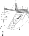
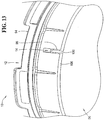
- the first sleeve 94 defines an insertion end 102 while the second sleeve includes a correspondingly sized flared out receptacle portion 104.
- the end 102 is telescopically received within the flared out receptacle portion 104 as shown in FIG 13 .
- the two sleeves 94, 96 are urged together until the end 102 engages one or both of the flanges 52 that form a part of the moisture release aperture 14, and/or bottoms out on the leading edge of the conical guide wall 108. Because the engagement of the two sleeves 94, 96 does not interrupt or close off the moisture release aperture 14, fluid disposed within the filter jacket 12 is still able to freely flow through the moisture release aperture 14 when two sleeves 94, 96 are joined.
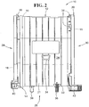
- the internal seal 18 is generally disposed inside the filter jacket 12 between the upstream end 28 and the downstream end 30. In a preferred embodiment, the internal seal 18 is circumferential and disposed closest to the upstream end 28 ( FIG. 2 ). As depicted in FIG. 7 , which illustrates a cross section of the filter jacket 12 taken about the internal seal 18, the internal seal is interposed between and preferably sealingly engages each of the filter jacket inner surface 22 and a filter media outer surface 72.
- One advantageous way to form the inner seal 18 is to dispense a continuous bead of sealing adhesive into the flared out receptacle portion 104, after the fluted filter media 16 has been installed and located in the second sleeve 96 (but without the first sleeve mounted).
- the combination of the fluted filter media 16 and the second sleeve 96 provide for a continuous annular groove that provides a receptacle for receipt of the bead of sealing adhesive (which is somewhat viscous fluid in the uncured state).
- This bead of adhesive is sufficiently thick enough that it engages and fully seals against the entire circumference and perimeter of both the inner wall of the jacket 12 (and more specifically the flared out receptacle portion of the second sleeve 16), as well as outer surface of the fluted filter media pack 16. As a result, it forms the inner seal 18 once the adhesive dries and cures to prevent short-circuiting of unfiltered fluid from the upstream to the downstream end through the filter element.
- the two sleeves 94, 96 of the jacket 12 can be held together by a friction fit or other appropriate coupling, preferably the two sleeves 94, 96 are integrally bonded by the internal seal 18 together to form the jacket 12.
- the first sleeve 94 is telescopically inserted into the second sleeve 96 and over the fluted filter media 16 such that it engages the adhesive to bond the sleeve components together.
- this construction also better ensures complete circumferential contact between the inner wall of the jacket to more reliably provide for the inner seal 18.
- the internal seal 18 is preferably formed from adhesive such as urethane or glue, but may comprise other suitable seal adhesive material to provide both for a sealing and bonding features. With this construction of the disclosed embodiment, a single bead of adhesive thus provides for two separate functions of preventing short-circuiting of fluid and also bonding components together.
- the bead of adhesive is however not laid overly thick so as to prevent obstruction of the moisture release aperture 14.
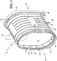
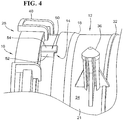
- the moisture release aperture 14, which is highlighted in FIG. 4 is adapted to permit a fluid (e.g., water) to be expelled from within the filter element 10.
- the moisture release aperture 14 is preferably covered and/or shrouded by an offset hood 50.
- the hood 50 may be integrally molded as a structure into the jacket 12, and preferably into the first sleeve 94.
- the offset hood 50 is generally spaced outwardly from the outer peripheral surface 24 of the jacket 12 by a pair of flanges 52 such that a cover 54 is positioned over the moisture release aperture 14.
- the moisture release aperture 14 is protectively covered without restricting a flow of fluid therethrough. With the moisture release aperture 14 sheltered in this manner, the fluted filter media 16 within the filter element 10 ( FIG. 1 ) is safe from punctures, tampering, and other damage while still leaving an open flow passage.
- the type of filter media 16 installed in the jacket 12 may take different forms, and is preferably of the axial flow type (depth media, fluted media are often axial, and even pleated media can be arranged for axial flow).
- One of the preferred forms from the standpoint of providing a high filtering capacity is fluted filter media 16 as illustrated.
- the aforementioned patents illustrate that the methods and constructions of fluted filter media are well known. Therefore, details herein will be relatively limited as additional reference can be had to these prior patent publications for reference.
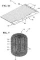
- the fluted filter media 16 preferably disposed within filter jacket 12 is illustrated in an uncoiled state in FIG. 6B . As shown, the fluted filter media 16 comprises a planar sheet 56 and a fluted sheet 58 of filter material intermittently bonded together and then coiled up.
- one or both of the planar sheet 56 and fluted sheet 58 are made of the same material and can comprise a natural material (e.g., cellulose filter paper) and/or a synthetic material.
- the fluted sheet 58 can be formed by corrugating or by forming close folds in a sheet filter paper so as to form alternating peaks and valleys.
- the fluted filter media 16 can be constructed by in a variety of different ways (e.g. such as with or without a winding board).
- a stitch adhesive 60 is intermittently centrally placed between the planar sheet 56 and fluted sheet 58 while another adhesive 62 (such as urethane) is preferably continuously placed proximate edges of the planar sheet and fluted sheet to form an "A" seal 62.
- These adhesives can be laid as a bead on either the fluted sheet 58 and/or the planar sheet 58 before the two sheets are joined together. Thereafter, the planar sheet 56 and fluted sheet 60 are collectively joined together to sandwich the adhesive material between the two sheets and bond the two sheets together.
- further stitch adhesive can be placed on an exposed face of either or both the planar sheet 56 and/or the fluted sheet 58 to provide for structure integrity of the rolled pack of fluted filter media 16 and prevent telescoping or other such failure of the fluted filter media when it is subjected to air flow and pressure.
- fluted filter media 16 having a plurality of flutes 70 ( FIG. 1 ) is formed.
- One group of flutes in the plurality of flutes 70 is closed proximate the upstream end 28 while another group of flutes in the plurality of flutes is closed proximate the downstream end 30.
- the flutes are closed by sealing the flutes shut, however the flutes may also be closed by crushing or other such closure means.
- the closure and sealing location may be located exactly at or somewhat spaced apart from an end of the filter media 16 (typically one seal bead is at the end face while the other one is recessed somewhat as shown in FIGS. 6A-C ). Proximate has been used herein to encompass all different potential arrangements and constructions of fluted filter media.
- the air will flow into the group of flutes 70 which are opened at the inlet face. As these flutes 70 are closed proximate the outlet face, air is forced through the filter paper and into flutes 70 that are open at the outlet face (and closed proximate the inlet face) to exit the filter media pack. As such, any contaminated air flowing through the fluted filter media 16 from the upstream end 28 to the downstream end 30 is forced through the fluted filter media and, therefore, cleaned with particulates and contaminants being trapped along the walls of the open inlet flutes.
- the internal seal 18 is generally disposed inside the filter jacket 12 between the upstream end 28 and the downstream end 30. In a preferred embodiment, the internal seal 18 is circumferential and disposed closest to the upstream end 28 ( FIG. 1 ). As depicted in FIG. 7 , which illustrates a cross section of the filter jacket 12 taken about the internal seal 18, the internal seal is interposed between and sealingly engages each of the filter jacket inner surface 22 and a filter media outer surface 72.
- the external seal 20 is a generally oval shaped, preferably compressible, seal material secured to a portion of the filter jacket 12 proximate the downstream end 30.
- the external seal 20 and the internal seal 18 are in spaced relation to each other and the fluted filter media 16 is disposed within and surrounded by the filter jacket 12.
- the disclosed embodiment utilizes a foamed urethane seal that is molded and directly mounted to the filter jacket 12, and more specifically the second sleeve 96 via an annular seal support member 74.
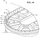
- the external seal 20 has been removed to reveal the annular seal support member 74 that is integrally formed on the filter jacket 12.
- the annular seal support member 74 is canted relative to the axis and includes differently canted sections to include a radially outwardly canted portion 76 and a radially inwardly canted portion 78. As illustrated, the radially inwardly canted portion 78 is disposed proximate the rib network 42.
- the outwardly canted portion 76 includes a plurality of perforations 80 or apertures formed therein.
- the perforations 80 receive the free-rising seal-forming material (e.g., such as a foaming urethane) that forms the external seal 20. Portions of seal material that project through the perforations 80 lock the external seal 20 to the annular seal support member 74.
- the seal material is generally permitted to flow around the annular seal support member 74 as well as into and through the perforations 80. When that material stiffens or coagulates, the solidified or hardened material within the perforations 80 locks and/or secures the newly formed external seal 20 to the seal support member 74.
- the second sleeve 96 and therefore the jacket 12 also includes a discontinuous flange 82.
- the discontinuous flange 82 extends radially outwardly from the outer annular wall 21 of the filter jacket 12 proximate the downstream end 30.
- the discontinuous flange 82 extends generally around the filter jacket 12, but is broken up into separate sections by intermittent gaps 84 in the sealing flange.
- the sealing flange 82 is utilized during manufacture to provide a cap or boundary for the foam urethane material, which during molding inherently will expand and free-rise.
- the intermittent gaps 84 permit the free-rising seal material to expand upwardly through the gaps and preferably beyond the sealing flange.
- gaps 84 By permitting the free-rising seal-forming material to rise at least partially through the gaps 84, proper or desired formation of the external seal 20 can be confirmed by visual inspection. For example, a person can inspect the various gaps 84 to confirm that seal material is at least partially projecting up into the gaps. If material is not foamed up into the gaps, then such an indication can indicate a potential problem with the seal molding process.
- Another separate benefit of the gaps 84 is that seal material will project up into the gaps thereby locking the external seal 20 to the filter jacket 12 in a location and plane different than the seal support member 74.
- Yet another potential advantage of the gaps is that they allow for venting of gas formed during the molding process of a foaming type urethane.
- the filter jacket 12 further includes a baffle 90 proximate the downstream end 30 which also assists in control over desired seal formation.
- the baffle 90 is disposed over the outlet face of the fluted filter media 16, with the baffle surface 92 axially spaced from the filter media 16.
- the baffle 90 projects radially inwardly from proximate the filter jacket inner surface 22 toward the downstream end 30.
- the baffle 90 includes a baffle surface 92 that is adapted and arranged to direct a flow of the free-rising seal material when the external seal 20 is formed during the molding process.
- the baffle surface 92 faces a free rise surface of the seal-forming material and guides the material during expansion.
- the baffle 90 is proximate the filter jacket inner surface 22 and also radially spaced from the filter jacket inner surface 22 to form an annular free rise expansion area and an annular gas vent 110 therebetween. As shown in both FIGS. 10 and 11 , the baffle 90 is spaced by and integrally supported by radially extending ribs of the rib network 86. In the annular expansion area between the baffle 90 and the filter jacket inner surface 22, the seal material is permitted to foam up (as defined by the directional arrows in FIG. 11A ) and form an irregular free rise surface 112. In contrast, the remainder of the external seal surface is regular and forms a molded, and thereby controllably shaped, surface 114.
- This molded surface 114 starts at the discontinuous flange 82 and wraps around the seal support member 74.
- the inner radial surface of the molded surface 114 is also closely toleranced and shaped to provide for a radial sealing surface that is adapted to form a seal against an appropriate sealing surface of a downstream duct or housing.
- the baffle 90 is arranged to direct the free rise surface 112 radially outward as the free rise surface extends toward the outlet face of the fluted filter media 16.
- the seal material of the external seal 20 may either contact the baffle 90 or be spaced from it.
- the baffle 90 directs the seal material away from fluted filter end face (and minimizes contact with the filter media end face should the free rise surface extend too high), and also maintains the integrity of the sealing surface provided along the inner radial periphery of the molded surface 114.
- the filter jacket 12 includes a web network 86 proximate the downstream end 30 that extends around the end face of the fluted filter media 16 for supporting the filter media (e.g., against air pressure generated during filtration).
- the web network 86 is adapted to support the fluted filter media 16 within the filter jacket 12 while still permitting fluid to pass.
- the web network 86 generally includes one or more individual ribs 88.
- the protrusions 38 When installed into an inline duct in a vehicle, the protrusions 38 are aligned with clamps on the duct and the bosses 34, 36 are aligned with mating portions of the housing on the vehicle. This ensures that the gravitational bottom 26 of the filter element 10 where the moisture release aperture 14 is located appropriately positioned with respect to the direction or pull of gravity. Thereafter, each of the protrusions 38 is preferably clamped to the duct and each of the bosses 34, 36 is secured to the housing of the vehicle to fix the position of the filter element 10.
- the filter element 10 receives a flow of contaminated and/or dirty air proximate the upstream end 28.
- the dirty air enters flutes proximate the upstream end 28, passes through the fluted filter media 16 such that the contaminants are removed from the dirty air, and cleaned or filtered air is expelled at the downstream end 30 by other ones of the flutes.
- the moisture release aperture 14 is preferably positioned to be at or near the gravitational bottom of the filter element 10, gravity is employed to naturally pull or extract the fluid. As such, any water that is found within the filter jacket 12 upstream of the internal seal 18 is permitted to drain or seep out.
- the contaminants extracted from the air passing through the filter element cause the filter element to wear out, cause the filter element to loose efficiency, plug the filter element, and the like.
- the filter element 10 is removed from the inline duct and replaced with a new filter element.
- the moisture release aperture 14 is thus replaced along with the filter element each time the filter element is replaced.
- the moisture release aperture 14 is not prone to clogging or obstructions, due to periodic replacement of the filter element.
Landscapes
- Chemical & Material Sciences (AREA)
- Chemical Kinetics & Catalysis (AREA)
- Filtering Of Dispersed Particles In Gases (AREA)
Claims (8)
- Élément de filtre destiné à être installé entre un conduit amont et un conduit aval comprenant :un étui de filtre (12) ayant une paroi externe annulaire (21) s'étendant de manière axiale, définissant une surface interne d'étui de filtre (22), une surface externe d'étui de filtre (24), un fond gravitationnel (26), une extrémité amont (28) et une extrémité aval (30) et ladite paroi externe annulaire (21) s'étendant entre l'extrémité amont (28) et l'extrémité aval (30),un milieu filtrant cannelé (16) se trouvant à l'intérieur de l'étui de filtre (12) et définissant une surface externe de milieu filtrant (72), le milieu filtrant cannelé (16) comprenant une pluralité de cannelures, les premières cannelures sélectionnées de la pluralité de cannelures étant fermées à proximité de l'extrémité amont (28) et les secondes cannelures sélectionnées de la pluralité de cannelures étant fermées à proximité de l'extrémité aval (30) ; etun joint d'étanchéité interne (18) intercalé entre et mettant en prise de manière étanche la surface interne d'étui de filtre (22) et la surface externe de milieu filtrant (72), le joint d'étanchéité interne (18) étant disposé entre l'extrémité amont (28) et l'extrémité aval (30) ; etune ouverture de libération d'humidité (14) à proximité du fond gravitationnel (26) formée à travers la paroi externe annulaire (21) s'étendant de manière axiale de l'étui de filtre (12), l'ouverture de libération d'humidité (14) étant positionnée en amont du joint d'étanchéité interne (18).
- Élément de filtre selon la revendication 1, dans lequel l'étui de filtre (12) comprend en outre un capot (50) aligné avec l'ouverture de libération d'humidité (14), le capot recouvrant de manière protectrice l'ouverture de libération d'humidité, dans lequel le capot (50) comprend des brides (52) et un couvercle (54), les brides (52) faisant saillie radialement vers l'extérieur à partir de l'étui de filtre (12), le couvercle (54) étant radialement espacé vers l'extérieur de l'étui de filtre (12) et couplé aux brides (52).
- Élément de filtre selon la revendication 1, dans lequel l'étui de filtre (12) comprend en outre un premier manchon (94) et un second manchon (96), le premier manchon (94) et le second manchon (96) étant couplés ensemble afin de former l'étui (12), le matériau du joint d'étanchéité interne (18) étant positionné au niveau d'une interface entre les premier (94) et second (96) manchons afin de relier les premier (94) et second (96) manchons ensemble, le premier manchon (94) et le second manchon (96) étant alignés de manière angulaire avec une encoche d'alignement (98) et une nervure d'alignement (100) sur le premier manchon (94) et le second manchon (96), respectivement ou vice versa, dans lequel la nervure d'alignement (100) fait saillie uniquement partiellement dans l'encoche d'alignement (98) laissant un espace ouvert qui forme l'ouverture de libération d'humidité (14).
- Élément de filtre selon la revendication 1, dans lequel l'étui de filtre (12) comprend en outre un premier manchon (94) et un second manchon (96), le premier manchon (94) et le second manchon (96) étant couplés ensemble afin de former l'étui (12), un matériau du joint d'étanchéité interne (18) étant positionné au niveau d'une interface entre les premier (94) et second (96) manchons afin de relier les premier (94) et second (96) manchons ensemble, le premier manchon (94) et le second manchon (96) étant alignés de manière angulaire avec une encoche d'alignement (98) et une nervure d'alignement (100) sur le premier manchon (94) et le second manchon (96), respectivement ou vice versa, dans lequel le premier manchon (94) est disposé à proximité de l'extrémité d'entrée et le second manchon est disposé à proximité de l'extrémité de sortie, l'ouverture de libération d'humidité (14) étant formée dans le premier manchon (94).
- Élément de filtre selon la revendication 1, dans lequel l'étui de filtre (14) est perméable au fluide en amont du joint d'étanchéité interne (18) par le biais de l'ouverture de libération d'humidité (14) et imperméable au fluide en aval du joint d'étanchéité interne (18).
- Élément de filtre selon la revendication 1, dans lequel l'élément de filtre comprend en outre un joint d'étanchéité externe (20) monté sur l'étui de filtre (12) à proximité de l'extrémité aval (30), dans lequel un élément de support de joint d'étanchéité annulaire (74) s'étend à partir de l'étui de filtre (12) à proximité de l'extrémité aval (30) et comprend une pluralité de perforations (80) espacées de manière circonférentielle, les perforations (80) étant adaptées pour recevoir et fixer un matériau formant joint d'étanchéité utilisé afin de former le joint d'étanchéité externe (20).
- Élément de filtre selon la revendication 1, dans lequel l'étui de filtre (12) est formé à partir d'un premier manchon (94) ayant une extrémité d'insertion et d'un second manchon (96) ayant une partie de réceptacle évasée vers l'extérieur, l'extrémité d'insertion étant reçue de manière télescopique dans la partie évasée vers l'extérieur.
- Élément de filtre selon la revendication 1, dans lequel l'étui de filtre (12) est formé à partir de plastique et définit des moyens pour positionner de manière gravitationnelle l'ouverture de libération d'humidité (14) à proximité d'un fond gravitationnel (26) de la surface interne d'étui de filtre (22).
Applications Claiming Priority (2)
| Application Number | Priority Date | Filing Date | Title |
|---|---|---|---|
| US11/357,788 US7753982B2 (en) | 2006-02-17 | 2006-02-17 | Filter with drained jacket, seal indicator/lock means, and seal baffle |
| PCT/US2007/003865 WO2007097954A2 (fr) | 2006-02-17 | 2007-02-12 | Filtre avec etui asseche, moyen d'indication / de blocage de joint et chicane de joint |
Publications (3)
| Publication Number | Publication Date |
|---|---|
| EP1996309A2 EP1996309A2 (fr) | 2008-12-03 |
| EP1996309A4 EP1996309A4 (fr) | 2014-11-05 |
| EP1996309B1 true EP1996309B1 (fr) | 2019-05-01 |
Family
ID=38426753
Family Applications (1)
| Application Number | Title | Priority Date | Filing Date |
|---|---|---|---|
| EP07750687.1A Active EP1996309B1 (fr) | 2006-02-17 | 2007-02-12 | Filtre avec etui asseche |
Country Status (7)
| Country | Link |
|---|---|
| US (1) | US7753982B2 (fr) |
| EP (1) | EP1996309B1 (fr) |
| JP (1) | JP4956557B2 (fr) |
| AU (1) | AU2007217983B2 (fr) |
| BR (1) | BRPI0707760A8 (fr) |
| CA (1) | CA2641786C (fr) |
| WO (1) | WO2007097954A2 (fr) |
Cited By (1)
| Publication number | Priority date | Publication date | Assignee | Title |
|---|---|---|---|---|
| EP3204140B1 (fr) * | 2014-10-10 | 2025-06-18 | Baldwin Filters, Inc. | Support de filtre et élément de filtre renforcés par adhésif |
Families Citing this family (80)
| Publication number | Priority date | Publication date | Assignee | Title |
|---|---|---|---|---|
| ZA973639B (en) * | 1996-04-26 | 1998-10-26 | Donaldson Co Inc | Fluted filter media |
| CA2516007C (fr) | 2003-02-11 | 2014-09-02 | Donaldson Company, Inc. | Agencements de filtres a air, elements de filtre pret a l'usage et procedes |
| EP1608453B1 (fr) | 2003-03-18 | 2010-06-02 | Donaldson Company, Inc. | Procede ameliores destines au bobinage de milieux filtrants z |
| EP2679293A1 (fr) | 2004-03-24 | 2014-01-01 | Donaldson Company, Inc. | Purificateur d'air |
| US7993434B2 (en) * | 2004-04-06 | 2011-08-09 | Oscar Moreno A | Disposable air filter assembly |
| GB0409548D0 (en) * | 2004-04-29 | 2004-06-02 | King S College London | Robotic hand |
| CN102258918B (zh) | 2004-04-30 | 2016-02-24 | 唐纳森公司 | 过滤器结构;外壳;组件及方法 |
| US7905936B2 (en) | 2004-04-30 | 2011-03-15 | Donaldson Company, Inc. | Filter arrangements; housing; assemblies; and, methods |
| US8048188B2 (en) | 2004-06-18 | 2011-11-01 | Donaldson Company, Inc. | Air cleaner arrangements; serviceable filter cartridge; and, methods |
| EP1781398B1 (fr) | 2004-07-20 | 2010-02-17 | Donaldson Company, Inc. | Agencement de garniture de materiaux filtrants z, cartouche filtrante, agencement d'epurateur d'air et procedes associes |
| US7931725B2 (en) | 2004-11-02 | 2011-04-26 | Baldwin Filters, Inc. | Fluted filter apparatus |
| US7318851B2 (en) | 2004-11-02 | 2008-01-15 | Baldwin Filters, Inc. | Filter element |
| US20110197556A1 (en) | 2004-11-02 | 2011-08-18 | Baldwin Filters, Inc. | Filter element |
| US7909954B2 (en) * | 2004-11-03 | 2011-03-22 | Baldwin Filters, Inc. | Method and apparatus for winding a filter media pack |
| US7569090B2 (en) * | 2004-11-12 | 2009-08-04 | Donaldson Company, Inc. | Method of forming filter arrangements; and, apparatus |
| DE102004059279B4 (de) * | 2004-12-09 | 2018-05-03 | Mann + Hummel Gmbh | Luftfilter |
| EP1937961B1 (fr) | 2005-10-11 | 2012-07-11 | Donaldson Company, Inc. | Element de filtre a air et ensemble de filtre a air |
| DE102006001126A1 (de) | 2006-01-09 | 2007-07-12 | Kettenbach Gmbh & Co. Kg | Dentalabformmassen, daraus hergestellte gehärtete Produkte und Verwendung von Tensiden zur Herstellung von Dentalabformmassen |
| US7708797B2 (en) | 2006-01-20 | 2010-05-04 | Donaldson Company, Inc. | Air cleaner configured for receipt of various sized filter cartridges; components thereof; and, methods |
| US7753982B2 (en) | 2006-02-17 | 2010-07-13 | Baldwin Filters, Inc. | Filter with drained jacket, seal indicator/lock means, and seal baffle |
| JP4661677B2 (ja) * | 2006-04-25 | 2011-03-30 | トヨタ紡織株式会社 | エアフィルタ及びその製造方法 |
| US7713321B2 (en) | 2006-06-22 | 2010-05-11 | Donaldson Company, Inc. | Air cleaner arrangements; components thereof; and, methods |
| US7972404B2 (en) | 2006-06-22 | 2011-07-05 | Donaldson Company, Inc. | Air cleaner arrangements; components thereof; and, methods |
| US10040020B2 (en) * | 2006-12-06 | 2018-08-07 | Baldwin Filters, Inc. | Fluid filter apparatus having filter media wound about a winding frame |
| US9757676B2 (en) | 2006-12-06 | 2017-09-12 | Baldwin Filters, Inc. | Method and apparatus for winding a filter element |
| EP2190554B1 (fr) * | 2007-09-07 | 2013-01-09 | Donaldson Company, Inc. | Ensemble filtre à air |
| US8460420B2 (en) * | 2007-09-07 | 2013-06-11 | Parker-Hannifin Corporation | Filter element |
| US9545593B2 (en) | 2007-11-01 | 2017-01-17 | Baldwin Filters, Inc. | Winding core pressure relief for fluted filter |
| CN101909719B (zh) | 2007-11-15 | 2014-01-22 | 唐纳森公司 | 空气过滤器结构,组件和方法 |
| US7959703B2 (en) | 2008-06-30 | 2011-06-14 | Baldwin Filters, Inc. | Fluted filter with integrated frame |
| US8048187B2 (en) | 2008-06-30 | 2011-11-01 | Baldwin Filters, Inc. | Filter frame attachment and fluted filter having same |
| CN102159297B (zh) * | 2008-07-22 | 2014-12-17 | 唐纳森公司 | 空气滤清器组件及其部件 |
| US8491684B2 (en) | 2009-02-27 | 2013-07-23 | Donaldson Company, Inc. | Filter cartridge; components thereof; and methods |
| US8506668B2 (en) * | 2009-03-30 | 2013-08-13 | Baldwin Filters, Inc. | Fluted filter with axial seal |
| US8287614B2 (en) * | 2009-08-10 | 2012-10-16 | Mann+Hummel Gmbh | Supplemental filter media support insert for an air cleaner |
| US9174160B2 (en) * | 2009-08-19 | 2015-11-03 | Baldwin Filters, Inc. | Collapsible core, filter, and method |
| GB2491081A (en) | 2010-03-17 | 2012-11-21 | Baldwin Filters Inc | Fluid filter |
| WO2011115979A2 (fr) | 2010-03-17 | 2011-09-22 | Baldwin Filters, Inc. | Filtre à fluides |
| WO2012037433A1 (fr) | 2010-09-16 | 2012-03-22 | Cummins Filtration Ip Inc. | Filtre doté de fonctions permettant d'améliorer la performance de prélavage, dispositif d'étanchéité et support structurel |
| CA2820306C (fr) | 2010-12-22 | 2018-08-14 | Cooper Technologies Company | Pre-filtration et detection de maintenance pour enceintes antideflagrantes |
| WO2012088186A2 (fr) | 2010-12-22 | 2012-06-28 | Cooper Technologies Company | Renforts structuraux destinés à des ensembles filtre |
| WO2012095419A1 (fr) * | 2011-01-11 | 2012-07-19 | Mann+Hummel Gmbh | Ensemble épurateur d'air et élément-filtre améliorant la rigidité dynamique des parois |
| US8721986B2 (en) * | 2011-09-09 | 2014-05-13 | Mann+Hummel Gmbh | Freshening clip cabin air cleaner |
| US9970394B2 (en) | 2012-07-25 | 2018-05-15 | Baldwin Filters, Inc. | Filter housing, fluted filter and safety filter |
| WO2014031623A1 (fr) | 2012-08-20 | 2014-02-27 | Ecolab Usa Inc. | Sorbants de mercure |
| USD710000S1 (en) | 2012-09-17 | 2014-07-29 | Evolution Air Filter, Inc. | Air filter frame fascia |
| RU2670852C9 (ru) | 2013-05-22 | 2018-11-30 | Дональдсон Компани, Инк. | Вертикальная система впуска воздуха, воздухоочиститель и фильтрующий элемент |
| DE102013019327B4 (de) * | 2013-11-20 | 2023-06-01 | Mann+Hummel Gmbh | Filterelement mit Filterbalg und Verwendung des Filterelements |
| ES2925798T3 (es) * | 2015-04-10 | 2022-10-19 | Mann & Hummel Gmbh | Elemento de filtro y disposición de filtro |
| EP3377192B1 (fr) | 2015-11-20 | 2023-06-14 | Baldwin Filters, Inc. | Support adhésif de cannelure pendant l'enroulement d'un ensemble cannelé |
| USD786935S1 (en) * | 2015-11-20 | 2017-05-16 | Baldwin Filters, Inc. | Filter element |
| USD798907S1 (en) | 2015-11-20 | 2017-10-03 | Baldwin Filters, Inc. | Filter element |
| US10682597B2 (en) | 2016-04-14 | 2020-06-16 | Baldwin Filters, Inc. | Filter system |
| EP3311902B1 (fr) * | 2016-10-24 | 2020-06-24 | Donaldson Company, Inc. | Élément filtre à air et son procédé de production |
| DE112018000692T5 (de) * | 2017-03-16 | 2019-10-17 | Cummins Filtration Ip, Inc. | Filtrationsabdichtungssystem |
| USD852345S1 (en) * | 2017-04-07 | 2019-06-25 | Champion Laboratories, Inc. | Filter |
| WO2019018465A1 (fr) | 2017-07-20 | 2019-01-24 | Cummins Filtration Ip, Inc. | Filtre à air à joint radial |
| USD885545S1 (en) * | 2017-08-09 | 2020-05-26 | Donaldson Company, Inc. | Filter cartridge |
| USD885546S1 (en) * | 2017-08-09 | 2020-05-26 | Donaldson Company, Inc. | Filter cartridge |
| KR102585171B1 (ko) | 2017-08-09 | 2023-10-05 | 도날드슨 컴파니, 인코포레이티드 | 필터 카트리지, 공기 청정기 조립체, 하우징, 특징부, 구성요소, 및 방법 |
| CN114642925B (zh) | 2017-12-08 | 2024-05-28 | 康明斯滤清系统知识产权公司 | 具有稳定轮廓的椭圆形密封件 |
| WO2019140045A1 (fr) | 2018-01-12 | 2019-07-18 | Cummins Filtration Ip, Inc. | Filtre à air facile à entretenir |
| FR3078490B1 (fr) | 2018-03-05 | 2022-10-14 | Cummins Filtration Sarl | Element filtrant et boitier ayant des sections transversales non circulaires |
| USD884866S1 (en) | 2018-05-08 | 2020-05-19 | Cummins Filtration Ip, Inc. | Filter element |
| US10918978B2 (en) | 2018-05-08 | 2021-02-16 | Cummins Filtration Ip, Inc. | Oval filter with exterior elliptical radial seal and internal support structure |
| CN113164856B (zh) * | 2018-11-28 | 2022-07-19 | 康明斯滤清系统知识产权公司 | 过滤元件上的弯曲密封件和保护性密封模具 |
| USD1002792S1 (en) | 2019-02-05 | 2023-10-24 | Donaldson Company, Inc. | Filter cartridge |
| WO2020163756A1 (fr) * | 2019-02-08 | 2020-08-13 | Donaldson Company, Inc. | Élément filtrant, ensemble épurateur d'air, et procédés |
| US12296291B2 (en) | 2019-11-18 | 2025-05-13 | Cummins Filtration Inc. | Low restriction air filter |
| USD969289S1 (en) | 2020-03-05 | 2022-11-08 | Cummins Filtration Inc. | Filter element |
| CN115397537B (zh) | 2020-04-14 | 2025-09-23 | 康明斯滤清系统公司 | 封闭端帽形成以不同轴向距离定位的密封部的过滤元件 |
| USD1064220S1 (en) | 2022-01-07 | 2025-02-25 | Donaldson Company, Inc. | Filter cartridge |
| USD1067404S1 (en) | 2022-01-07 | 2025-03-18 | Donaldson Company, Inc. | Filter cartridge |
| US20240042361A1 (en) * | 2022-08-06 | 2024-02-08 | Baldwin Filters, Inc. | Embedding variable slit width embossed filter media packs |
| US12146679B1 (en) | 2023-06-07 | 2024-11-19 | Filtrex Pure Air, Llc | Toolless installation of vent assembly |
| US12313284B2 (en) | 2023-06-07 | 2025-05-27 | Filtrex Pure Air, Llc | Toolless installation and cleaning of vent assembly |
| USD1114976S1 (en) | 2023-08-23 | 2026-02-24 | Donaldson Company, Inc. | Filter cartridge |
| USD1112684S1 (en) | 2023-08-23 | 2026-02-10 | Donaldson Company, Inc. | Filter cartridge |
| IT202300019446A1 (it) * | 2023-09-21 | 2025-03-21 | Gvs Filter Tech Uk Ltd | Filtro dell'aria per dispositivo di respirazione |
| WO2025189231A1 (fr) * | 2024-03-11 | 2025-09-18 | Breathesafe Pty Ltd | Système de traitement d'air |
Family Cites Families (143)
| Publication number | Priority date | Publication date | Assignee | Title |
|---|---|---|---|---|
| US1947066A (en) | 1932-12-14 | 1934-02-13 | Samuel M Langston Co | Corrugator |
| US1954881A (en) | 1933-03-23 | 1934-04-17 | Samuel M Langston Co | Corrugator |
| US1943080A (en) | 1933-04-21 | 1934-01-09 | Samuel M Langston | Corrugator |
| US3025963A (en) * | 1958-03-13 | 1962-03-20 | Russell H Curtis | Products useful as filtering devices and methods of making them |
| US3255889A (en) | 1961-04-10 | 1966-06-14 | American Mach & Foundry | Wound filter |
| SE302235B (fr) | 1966-02-08 | 1968-07-08 | Svenska Flaektfabriken Ab | |
| GB1121896A (en) | 1966-07-21 | 1968-07-31 | Gen Motors Ltd | Air filters |
| US3676247A (en) | 1969-02-03 | 1972-07-11 | Australian Paper Manufacturers | Corrugating paperboard |
| US3679057A (en) | 1970-09-11 | 1972-07-25 | Damasco Rodolfo Adelto Perez | Screen filter pack and method for making same |
| US4253228A (en) | 1978-09-14 | 1981-03-03 | Filterspun, Inc. | Apparatus and system for forming wound filters |
| US4252591A (en) | 1979-05-02 | 1981-02-24 | Pall Corporation | Corrugating apparatus and process |
| US4257790A (en) | 1979-10-10 | 1981-03-24 | Henningsen Foods, Inc. | Quick change filter bag arrangement |
| DE3271301D1 (en) * | 1981-02-23 | 1986-07-03 | Nippon Denso Co | Fluid cleaner systems |
| US4410427A (en) * | 1981-11-02 | 1983-10-18 | Donaldson Company, Inc. | Fluid filtering device |
| US4579698A (en) | 1982-05-28 | 1986-04-01 | Amf, Inc. | Process for producing a microporous polymeric filter membrane with adjacent non-porous edge layers and a pleated filter element formed from the membrane |
| JPS60112320A (ja) | 1983-11-24 | 1985-06-18 | Hitachi Ltd | トライステ−トゲ−トの保護方式 |
| JPS60124622U (ja) | 1984-01-31 | 1985-08-22 | 株式会社 土屋製作所 | ハニカムエレメント内装のエアクリ−ナ |
| SE452598B (sv) | 1985-06-20 | 1987-12-07 | Flodins Filter Ab | Forfarande och anordning for framstellning av filter |
| US4747944A (en) * | 1986-04-29 | 1988-05-31 | Midwest Conservation Specialties, Inc. | Recirculating filter system |
| US4720292B1 (en) * | 1986-07-14 | 1991-09-10 | Cylindrical air filter with lightweight housing and radially directed seal | |
| GB8621660D0 (en) * | 1986-09-09 | 1986-10-15 | Domnick Hunter Filters Ltd | Filter element |
| SE455378B (sv) | 1986-11-17 | 1988-07-11 | Flodins Filter Ab | Forfarande for framstellning av filter |
| DE8810295U1 (de) * | 1988-08-13 | 1988-10-13 | Stanelle, Karl-Heinz, 7129 Güglingen | Filterpatrone |
| US5346675A (en) | 1988-12-16 | 1994-09-13 | Usui Kokusai Sangyo Kabushiki Kaisha | Exhaust gas cleaning apparatus |
| US4976857A (en) | 1989-05-03 | 1990-12-11 | Newport Filters, Inc. | Filter element and fabrication methodology |
| JPH038568U (fr) * | 1989-06-14 | 1991-01-28 | ||
| US5238474A (en) * | 1990-10-19 | 1993-08-24 | Donaldson Company, Inc. | Filtration arrangement |
| US5213275A (en) | 1991-07-17 | 1993-05-25 | General Dynamics Corporation, Space Systems Division | Reeding edge for securing in place fiber band during filament winding operation |
| US5245897A (en) | 1991-11-25 | 1993-09-21 | E. I. Du Pont De Nemours And Company | System and method for advancing the leading edge of a corrugated web |
| DK0558872T3 (da) | 1992-03-04 | 1996-09-16 | Ciba Geigy Ag | Fremgangsmåde og indretning til opvikling af opviklelige substrater |
| JP3239517B2 (ja) | 1992-06-17 | 2001-12-17 | 株式会社デンソー | 濾過エレメントの製造方法 |
| DE4223723C2 (de) | 1992-07-18 | 1996-08-29 | Mann & Hummel Filter | Verfahren und Vorrichtung zur Herstellung eines zickzackförmig gefalteten Filters |
| US5484466A (en) * | 1994-02-14 | 1996-01-16 | Baldwin Filters, Inc. | Air filter element with radial seal sealing gasket |
| JPH07236803A (ja) * | 1994-02-28 | 1995-09-12 | Tsuchiya Mfg Co Ltd | 内燃機関用使い捨て型オイルフィルタ |
| SE506017C2 (sv) | 1994-05-10 | 1997-11-03 | Volvo Ab | Luftfilter |
| WO1995035202A1 (fr) | 1994-06-21 | 1995-12-28 | Miller Ray R | Procede de liaison de feuilles et stratifies resultants |
| US5938804A (en) * | 1994-11-23 | 1999-08-17 | Donaldson Company, Inc. | Reverse flow air filter arrangement and method |
| US5588945A (en) | 1995-02-21 | 1996-12-31 | Corrugated Gear & Services, Inc. | Method and device for spacing a corrugating finger relative to a corrugating roll |
| US5685985A (en) | 1995-12-20 | 1997-11-11 | Baldwin Filters, Inc. | Environmentally friendly filter cartridge |
| DE19654188C5 (de) | 1995-12-26 | 2010-09-23 | Toyoda Boshoku Corp., Kariya-shi | Filterelement und Verfahren für dessen Herstellung |
| US5792247A (en) * | 1996-04-26 | 1998-08-11 | Donaldson Company, Inc. | Integrated resonator and filter apparatus |
| US5895574A (en) * | 1996-04-26 | 1999-04-20 | Donaldson Company, Inc. | Rolled liquid filter using fluted media |
| ZA973639B (en) | 1996-04-26 | 1998-10-26 | Donaldson Co Inc | Fluted filter media |
| US5902364A (en) * | 1996-04-26 | 1999-05-11 | Donaldson Company, Inc. | Conical filter |
| US5772883A (en) | 1996-04-26 | 1998-06-30 | Donaldson Company, Inc. | Slanted inline filter |
| US5820646A (en) * | 1996-04-26 | 1998-10-13 | Donaldson Company, Inc. | Inline filter apparatus |
| US6022305A (en) | 1998-03-11 | 2000-02-08 | Aaf International | Pleating apparatus |
| EP0999200B1 (fr) * | 1998-11-04 | 2002-07-17 | Rohm And Haas Company | Procédé de préparation avec un rendement élevé du méthacrylate de méthyle ou de l'acide acrylique |
| USD450827S1 (en) | 1999-02-26 | 2001-11-20 | Donaldson Company, Inc. | Filter element having sealing system |
| US6235195B1 (en) * | 1999-02-26 | 2001-05-22 | Donaldson Company, Inc. | Filter element incorporating a handle member |
| US6210469B1 (en) | 1999-02-26 | 2001-04-03 | Donaldson Company, Inc. | Air filter arrangement having first and second filter media dividing a housing and methods |
| US6190432B1 (en) * | 1999-02-26 | 2001-02-20 | Donaldson Company, Inc. | Filter arrangement; sealing system; and methods |
| US6179890B1 (en) * | 1999-02-26 | 2001-01-30 | Donaldson Company, Inc. | Air cleaner having sealing arrangement between media arrangement and housing |
| CA2360445C (fr) * | 1999-02-26 | 2011-01-25 | Donaldson Company, Inc. | Dispositif de filtration, systeme de scellement et methodes |
| USD461003S1 (en) | 1999-02-26 | 2002-07-30 | Donaldson Company, Inc. | Filter element having sealing system |
| US6221122B1 (en) * | 1999-02-26 | 2001-04-24 | Donaldson Company, Inc. | Filter element and methods |
| DE19935297A1 (de) | 1999-07-27 | 2001-02-01 | Mahle Filtersysteme Gmbh | Filterkörper eines Fluidfilters, insbesondere Luftfilters |
| USD437402S1 (en) | 1999-11-05 | 2001-02-06 | Donaldson Company, Inc. | Filter element with centerpiece |
| US6348084B1 (en) | 1999-11-05 | 2002-02-19 | Donaldson Company, Inc. | Filter element, air cleaner, and methods |
| US6348085B1 (en) | 1999-11-10 | 2002-02-19 | Donaldson Company, Inc. | Filter arrangement and methods |
| US6416605B1 (en) | 1999-11-24 | 2002-07-09 | Donaldson Company, Inc. | Method for manufacturing fluted media |
| US6290739B1 (en) * | 1999-12-29 | 2001-09-18 | Donaldson Company, Inc. | Aerosol separator; and method |
| US6436162B1 (en) | 2000-03-22 | 2002-08-20 | Nelson Industries, Inc. | Twist and lock filter housing with anti-rotation stop |
| DE10023427A1 (de) | 2000-05-12 | 2001-11-15 | Mann & Hummel Filter | Flüssigkeitsfilter mit in Urformtechnik hergestelltem Gehäuse und Verfahren zu seiner Herstellung |
| US6946012B1 (en) | 2000-05-18 | 2005-09-20 | Fleetguard, Inc. | Filter and forming system |
| US6368374B1 (en) * | 2000-06-13 | 2002-04-09 | Donaldson Company, Inc. | Filter arrangement and methods |
| USD450828S1 (en) | 2000-06-13 | 2001-11-20 | Donaldson Company, Inc. | Fluted filter element having a handle |
| US6800117B2 (en) * | 2000-09-05 | 2004-10-05 | Donaldson Company, Inc. | Filtration arrangement utilizing pleated construction and method |
| US6743273B2 (en) | 2000-09-05 | 2004-06-01 | Donaldson Company, Inc. | Polymer, polymer microfiber, polymer nanofiber and applications including filter structures |
| US6673136B2 (en) * | 2000-09-05 | 2004-01-06 | Donaldson Company, Inc. | Air filtration arrangements having fluted media constructions and methods |
| US6402798B1 (en) | 2000-09-19 | 2002-06-11 | Nelson Industries, Inc. | Twist and lock filter housing with nontorsional anti-rotation stop |
| US6511599B2 (en) | 2000-12-18 | 2003-01-28 | Nelson Industries, Inc. | Multi-element cylindrical filter with equalized flow |
| US6743317B2 (en) * | 2000-12-19 | 2004-06-01 | Robert M. Wydeven | Method of sealing, housing and constructing honeycomb filters |
| US6797027B2 (en) * | 2001-04-11 | 2004-09-28 | Donaldson Company, Inc. | Filter assemblies and systems for intake air for fuel cells |
| US6447567B1 (en) * | 2001-05-14 | 2002-09-10 | Baldwin Filters, Inc. | Air filter element with integral radial seal gasket |
| RU2300543C2 (ru) | 2001-05-31 | 2007-06-10 | Дональдсон Компани, Инк. | Составы тонкого волокна, способы их получения, способ изготовления тонковолокнистого материала |
| US6610126B2 (en) | 2001-06-06 | 2003-08-26 | Donaldson Company, Inc. | Filter element having sealing members and methods |
| USD460169S1 (en) | 2001-06-06 | 2002-07-09 | Donaldson Company Inc. | Filter element having an inlet grid |
| US6517598B2 (en) * | 2001-06-06 | 2003-02-11 | Donaldson Company, Inc. | Filter element having flange and methods |
| US6852141B2 (en) | 2001-06-06 | 2005-02-08 | Donaldson Company, Inc. | Filter element having center piece and methods |
| DE10152552A1 (de) * | 2001-10-24 | 2003-05-08 | Mann & Hummel Filter | Filterelement, insbesondere für die Filtrierung von Flüssigkeiten |
| JP3946027B2 (ja) * | 2001-10-29 | 2007-07-18 | 和興フィルタテクノロジー株式会社 | エアクリーナー |
| EP1453588B1 (fr) | 2001-12-03 | 2010-06-30 | Donaldson Company, Inc. | Support, element de filtre faisant appel a une feuille de support ondulee, feuille ondulee, et procedes associes |
| USD473637S1 (en) | 2001-12-03 | 2003-04-22 | Donaldson Company, Inc. | Fluted filter element |
| USD483459S1 (en) | 2002-01-23 | 2003-12-09 | Donaldson Company, Inc. | Air filter element for engine |
| US6966940B2 (en) | 2002-04-04 | 2005-11-22 | Donaldson Company, Inc. | Air filter cartridge |
| US6851569B2 (en) | 2002-04-22 | 2005-02-08 | Plastican, Inc. | Reusable lid and container |
| KR100956706B1 (ko) | 2002-05-09 | 2010-05-06 | 도날드슨 컴파니, 인코포레이티드 | 풀루트 필터 매체를 갖는 에어 필터 |
| GB2389323B (en) | 2002-06-07 | 2005-08-17 | Baldwin Filters Inc | Environmentally friendly filter cartridge |
| DE10227050B3 (de) | 2002-06-17 | 2004-01-29 | Albert Frey Verpackungsentwicklungen Und Vertriebs-Gmbh | Wellpappe mit Aufreißlinie |
| KR101009857B1 (ko) | 2002-07-10 | 2011-01-19 | 도날드슨 컴파니, 인코포레이티드 | 플루트 필터 매체 및 그 제조방법 |
| US6703675B1 (en) * | 2002-08-20 | 2004-03-09 | Memx, Inc. | Particle filter for partially enclosed microelectromechanical systems |
| US6959819B2 (en) | 2002-10-08 | 2005-11-01 | Pti Technologies, Inc. | Fatigue rated glass filled plastic filter assembly incorporating a coreless plastic filter element with integral seal |
| US7537631B2 (en) * | 2002-10-28 | 2009-05-26 | Donaldson Company, Inc. | Filter cartridges; air cleaners; and methods |
| USD497202S1 (en) * | 2002-11-22 | 2004-10-12 | Donaldson Company, Inc. | Filter for engine |
| DE60327890D1 (de) | 2002-12-11 | 2009-07-16 | Donaldson Co Inc | Z-filtermedien mit gegenstromreinigungssystemen und -verfahren |
| US6887343B2 (en) | 2002-12-20 | 2005-05-03 | Fleetguard, Inc. | Filter coating, winding, finishing and manufacturing system |
| USD484584S1 (en) | 2003-01-22 | 2003-12-30 | Donaldson Company, Inc. | Filter element for engine |
| CA2516007C (fr) | 2003-02-11 | 2014-09-02 | Donaldson Company, Inc. | Agencements de filtres a air, elements de filtre pret a l'usage et procedes |
| EP1608453B1 (fr) | 2003-03-18 | 2010-06-02 | Donaldson Company, Inc. | Procede ameliores destines au bobinage de milieux filtrants z |
| US7008465B2 (en) | 2003-06-19 | 2006-03-07 | Donaldson Company, Inc. | Cleanable high efficiency filter media structure and applications for use |
| US7458468B2 (en) | 2003-08-05 | 2008-12-02 | Purolator Filters Na Llc | Fuel filter diverter |
| US20070137152A1 (en) | 2003-10-17 | 2007-06-21 | Jian Xu | Precleaner arrangement for use in air filtration, method of operation of precleaner and air cleaner comprising the precleaner arrangement |
| EP1718390B2 (fr) | 2003-11-12 | 2015-02-25 | Donaldson Company, Inc. | Filtre a air possedant un montage coulissant pour un element filtrant |
| WO2005058461A1 (fr) | 2003-12-16 | 2005-06-30 | Donaldson Company, Inc. | Systeme de filtre a air et procedes associes |
| WO2007056589A2 (fr) | 2005-11-09 | 2007-05-18 | Donaldson Company, Inc. | Dispositif d’etancheite destine a un element filtrant, ensemble element filtrant et procedes |
| EP1713561B1 (fr) | 2003-12-22 | 2014-12-10 | Donaldson Company, Inc. | Element filtrant muni d'un element d'etancheite et procede de fabrication. |
| WO2005082484A1 (fr) | 2004-02-09 | 2005-09-09 | Donaldson Company, Inc. | Supports filtrants ondules et plisses |
| WO2005077487A1 (fr) | 2004-02-10 | 2005-08-25 | Donaldson Company, Inc. | Ensemble de couches filtrantes, structures de filtre et procedes |
| WO2005079954A1 (fr) | 2004-02-17 | 2005-09-01 | Donaldson Company, Inc. | Systemes de filtre a air, elements filtrants reutilisables, et methodes s'y rapportant |
| US7311748B2 (en) * | 2004-03-02 | 2007-12-25 | Parker-Hannifin Corporation | Air filter assembly system and method |
| EP2679293A1 (fr) | 2004-03-24 | 2014-01-01 | Donaldson Company, Inc. | Purificateur d'air |
| USD506539S1 (en) | 2004-03-24 | 2005-06-21 | Donaldson Company, Inc. | Filter cartridge |
| US7905936B2 (en) | 2004-04-30 | 2011-03-15 | Donaldson Company, Inc. | Filter arrangements; housing; assemblies; and, methods |
| MX347553B (es) | 2004-06-08 | 2017-05-02 | Donaldson Company Inc * | Arreglo de paquete de medios de filtro-z y métodos. |
| EP1771237B2 (fr) | 2004-06-14 | 2018-10-10 | Donaldson Company, Inc. | Dispositif et procedes de filtrage de l'air |
| US8048188B2 (en) | 2004-06-18 | 2011-11-01 | Donaldson Company, Inc. | Air cleaner arrangements; serviceable filter cartridge; and, methods |
| EP1781398B1 (fr) * | 2004-07-20 | 2010-02-17 | Donaldson Company, Inc. | Agencement de garniture de materiaux filtrants z, cartouche filtrante, agencement d'epurateur d'air et procedes associes |
| WO2006014941A2 (fr) | 2004-07-26 | 2006-02-09 | Donaldson Company, Inc. | Système constitué d'un ensemble de couches filtrantes en z et procédés |
| GB0417458D0 (en) * | 2004-08-05 | 2004-09-08 | Domnick Hunter Ltd | Filter assembly |
| EP3135363B1 (fr) | 2004-08-06 | 2021-06-30 | Donaldson Company, Inc. | Agencement de filtre à air, ensemble et procédés |
| US20060091064A1 (en) | 2004-11-02 | 2006-05-04 | Baldwin Filters, Inc. | Filter apparatus with separable seal support frame |
| US20060091084A1 (en) | 2004-11-02 | 2006-05-04 | Baldwin Filters, Inc. | Fluted filter media with intermediate flow restriction and method of making same |
| US7318851B2 (en) | 2004-11-02 | 2008-01-15 | Baldwin Filters, Inc. | Filter element |
| US20070186528A1 (en) * | 2006-02-15 | 2007-08-16 | Baldwin Filters, Inc. | Fluted filter apparatus |
| US20060091061A1 (en) | 2004-11-02 | 2006-05-04 | Baldwin Filters, Inc. | Filter assembly with sealing system |
| US8042694B2 (en) | 2004-11-02 | 2011-10-25 | Baldwin Filters, Inc. | Gathered filter media for an air filter and method of making same |
| US7255300B2 (en) | 2004-11-03 | 2007-08-14 | Baldwin Filters, Inc. | Method and apparatus for winding a filter media pack |
| BRPI0606625B1 (pt) | 2005-01-13 | 2018-06-19 | Donaldson Company, Inc. | Cartucho de filtro de ar e conjunto de filtro de ar |
| CN101137424B (zh) | 2005-01-13 | 2011-12-28 | 唐纳森公司 | 空气过滤器滤筒和空气滤清器组件 |
| US8083825B2 (en) | 2005-02-28 | 2011-12-27 | Donaldson Company, Inc. | Filter arrangement and method |
| WO2007009039A1 (fr) | 2005-07-13 | 2007-01-18 | Donaldson Company, Inc. | Cartouche de filtre a air et filtre a air |
| EP1937961B1 (fr) | 2005-10-11 | 2012-07-11 | Donaldson Company, Inc. | Element de filtre a air et ensemble de filtre a air |
| US7708797B2 (en) | 2006-01-20 | 2010-05-04 | Donaldson Company, Inc. | Air cleaner configured for receipt of various sized filter cartridges; components thereof; and, methods |
| US7753982B2 (en) | 2006-02-17 | 2010-07-13 | Baldwin Filters, Inc. | Filter with drained jacket, seal indicator/lock means, and seal baffle |
| US7625419B2 (en) | 2006-05-10 | 2009-12-01 | Donaldson Company, Inc. | Air filter arrangement; assembly; and, methods |
| US20080000826A1 (en) | 2006-06-12 | 2008-01-03 | Harder David B | Rolled axial flow filter and methods |
| US7713321B2 (en) | 2006-06-22 | 2010-05-11 | Donaldson Company, Inc. | Air cleaner arrangements; components thereof; and, methods |
| US7972404B2 (en) | 2006-06-22 | 2011-07-05 | Donaldson Company, Inc. | Air cleaner arrangements; components thereof; and, methods |
| WO2008045325A2 (fr) | 2006-10-06 | 2008-04-17 | Donaldson Company, Inc. | Ensemble filtre à air, cartouche de filtre à air, et procédé permettant l'entretien d'un ensemble filtre à air |
| EP2514506B1 (fr) | 2007-02-02 | 2019-08-14 | Donaldson Company, Inc. | Ensemble de supports de filtration d'air et procédés |
| WO2008098185A1 (fr) | 2007-02-09 | 2008-08-14 | Donaldson Company, Inc. | Elément de filtre de combinaison |
| CN105107279B (zh) | 2007-02-26 | 2017-04-12 | 唐纳森公司 | 空气过滤装置;空气滤清器组件和方法 |
-
2006
- 2006-02-17 US US11/357,788 patent/US7753982B2/en active Active
-
2007
- 2007-02-12 AU AU2007217983A patent/AU2007217983B2/en active Active
- 2007-02-12 BR BRPI0707760A patent/BRPI0707760A8/pt not_active Application Discontinuation
- 2007-02-12 WO PCT/US2007/003865 patent/WO2007097954A2/fr not_active Ceased
- 2007-02-12 CA CA 2641786 patent/CA2641786C/fr active Active
- 2007-02-12 JP JP2008555317A patent/JP4956557B2/ja active Active
- 2007-02-12 EP EP07750687.1A patent/EP1996309B1/fr active Active
Cited By (1)
| Publication number | Priority date | Publication date | Assignee | Title |
|---|---|---|---|---|
| EP3204140B1 (fr) * | 2014-10-10 | 2025-06-18 | Baldwin Filters, Inc. | Support de filtre et élément de filtre renforcés par adhésif |
Also Published As
| Publication number | Publication date |
|---|---|
| EP1996309A2 (fr) | 2008-12-03 |
| EP1996309A4 (fr) | 2014-11-05 |
| JP2009526648A (ja) | 2009-07-23 |
| US20070193236A1 (en) | 2007-08-23 |
| WO2007097954A3 (fr) | 2008-01-17 |
| AU2007217983A1 (en) | 2007-08-30 |
| BRPI0707760A8 (pt) | 2018-04-24 |
| BRPI0707760A2 (pt) | 2011-05-10 |
| JP4956557B2 (ja) | 2012-06-20 |
| US7753982B2 (en) | 2010-07-13 |
| CA2641786A1 (fr) | 2007-08-30 |
| WO2007097954A2 (fr) | 2007-08-30 |
| CA2641786C (fr) | 2013-11-26 |
| AU2007217983B2 (en) | 2011-02-03 |
Similar Documents
| Publication | Publication Date | Title |
|---|---|---|
| EP1996309B1 (fr) | Filtre avec etui asseche | |
| US20250135384A1 (en) | Filter Elements, Air Cleaner Assemblies, and Methods of Use and Assembly | |
| CN114151246B (zh) | 空气滤清器组件 | |
| KR102891478B1 (ko) | 필터 카트리지 및 공기 청정기 조립체 | |
| US11951433B2 (en) | Air cleaner assemblies and methods of use | |
| CN103736326B (zh) | 过滤器元件,空气过滤器组件及方法 | |
| CA2642345C (fr) | Appareil filtrant cannele | |
| AU2014236577B2 (en) | Rectangular stacked fluted filter cartridge | |
| US20130000267A1 (en) | Fluid Filter | |
| CN114797328A (zh) | 过滤器滤芯;空气滤清器组件;外壳;特征;部件;以及方法 | |
| RU2817594C1 (ru) | Фильтрующие элементы, воздухоочистительные узлы и способы применения и сборки |
Legal Events
| Date | Code | Title | Description |
|---|---|---|---|
| PUAI | Public reference made under article 153(3) epc to a published international application that has entered the european phase |
Free format text: ORIGINAL CODE: 0009012 |
|
| 17P | Request for examination filed |
Effective date: 20080911 |
|
| AK | Designated contracting states |
Kind code of ref document: A2 Designated state(s): AT BE BG CH CY CZ DE DK EE ES FI FR GB GR HU IE IS IT LI LT LU LV MC NL PL PT RO SE SI SK TR |
|
| RIC1 | Information provided on ipc code assigned before grant |
Ipc: B01D 39/00 20060101AFI20090121BHEP |
|
| DAX | Request for extension of the european patent (deleted) | ||
| A4 | Supplementary search report drawn up and despatched |
Effective date: 20141006 |
|
| RIC1 | Information provided on ipc code assigned before grant |
Ipc: B01D 46/52 20060101ALI20140929BHEP Ipc: B01D 46/00 20060101ALI20140929BHEP Ipc: B01D 39/00 20060101AFI20140929BHEP |
|
| STAA | Information on the status of an ep patent application or granted ep patent |
Free format text: STATUS: EXAMINATION IS IN PROGRESS |
|
| 17Q | First examination report despatched |
Effective date: 20170412 |
|
| GRAP | Despatch of communication of intention to grant a patent |
Free format text: ORIGINAL CODE: EPIDOSNIGR1 |
|
| STAA | Information on the status of an ep patent application or granted ep patent |
Free format text: STATUS: GRANT OF PATENT IS INTENDED |
|
| INTG | Intention to grant announced |
Effective date: 20181116 |
|
| GRAS | Grant fee paid |
Free format text: ORIGINAL CODE: EPIDOSNIGR3 |
|
| GRAA | (expected) grant |
Free format text: ORIGINAL CODE: 0009210 |
|
| STAA | Information on the status of an ep patent application or granted ep patent |
Free format text: STATUS: THE PATENT HAS BEEN GRANTED |
|
| AK | Designated contracting states |
Kind code of ref document: B1 Designated state(s): AT BE BG CH CY CZ DE DK EE ES FI FR GB GR HU IE IS IT LI LT LU LV MC NL PL PT RO SE SI SK TR |
|
| REG | Reference to a national code |
Ref country code: GB Ref legal event code: FG4D |
|
| REG | Reference to a national code |
Ref country code: CH Ref legal event code: EP Ref country code: AT Ref legal event code: REF Ref document number: 1126160 Country of ref document: AT Kind code of ref document: T Effective date: 20190515 |
|
| REG | Reference to a national code |
Ref country code: DE Ref legal event code: R096 Ref document number: 602007058246 Country of ref document: DE |
|
| REG | Reference to a national code |
Ref country code: IE Ref legal event code: FG4D |
|
| REG | Reference to a national code |
Ref country code: NL Ref legal event code: MP Effective date: 20190501 |
|
| REG | Reference to a national code |
Ref country code: LT Ref legal event code: MG4D |
|
| PG25 | Lapsed in a contracting state [announced via postgrant information from national office to epo] |
Ref country code: LT Free format text: LAPSE BECAUSE OF FAILURE TO SUBMIT A TRANSLATION OF THE DESCRIPTION OR TO PAY THE FEE WITHIN THE PRESCRIBED TIME-LIMIT Effective date: 20190501 Ref country code: SE Free format text: LAPSE BECAUSE OF FAILURE TO SUBMIT A TRANSLATION OF THE DESCRIPTION OR TO PAY THE FEE WITHIN THE PRESCRIBED TIME-LIMIT Effective date: 20190501 Ref country code: FI Free format text: LAPSE BECAUSE OF FAILURE TO SUBMIT A TRANSLATION OF THE DESCRIPTION OR TO PAY THE FEE WITHIN THE PRESCRIBED TIME-LIMIT Effective date: 20190501 Ref country code: PT Free format text: LAPSE BECAUSE OF FAILURE TO SUBMIT A TRANSLATION OF THE DESCRIPTION OR TO PAY THE FEE WITHIN THE PRESCRIBED TIME-LIMIT Effective date: 20190901 Ref country code: NL Free format text: LAPSE BECAUSE OF FAILURE TO SUBMIT A TRANSLATION OF THE DESCRIPTION OR TO PAY THE FEE WITHIN THE PRESCRIBED TIME-LIMIT Effective date: 20190501 Ref country code: ES Free format text: LAPSE BECAUSE OF FAILURE TO SUBMIT A TRANSLATION OF THE DESCRIPTION OR TO PAY THE FEE WITHIN THE PRESCRIBED TIME-LIMIT Effective date: 20190501 |
|
| PG25 | Lapsed in a contracting state [announced via postgrant information from national office to epo] |
Ref country code: BG Free format text: LAPSE BECAUSE OF FAILURE TO SUBMIT A TRANSLATION OF THE DESCRIPTION OR TO PAY THE FEE WITHIN THE PRESCRIBED TIME-LIMIT Effective date: 20190801 Ref country code: GR Free format text: LAPSE BECAUSE OF FAILURE TO SUBMIT A TRANSLATION OF THE DESCRIPTION OR TO PAY THE FEE WITHIN THE PRESCRIBED TIME-LIMIT Effective date: 20190802 Ref country code: LV Free format text: LAPSE BECAUSE OF FAILURE TO SUBMIT A TRANSLATION OF THE DESCRIPTION OR TO PAY THE FEE WITHIN THE PRESCRIBED TIME-LIMIT Effective date: 20190501 |
|
| REG | Reference to a national code |
Ref country code: AT Ref legal event code: MK05 Ref document number: 1126160 Country of ref document: AT Kind code of ref document: T Effective date: 20190501 |
|
| PG25 | Lapsed in a contracting state [announced via postgrant information from national office to epo] |
Ref country code: IS Free format text: LAPSE BECAUSE OF FAILURE TO SUBMIT A TRANSLATION OF THE DESCRIPTION OR TO PAY THE FEE WITHIN THE PRESCRIBED TIME-LIMIT Effective date: 20190901 |
|
| PG25 | Lapsed in a contracting state [announced via postgrant information from national office to epo] |
Ref country code: DK Free format text: LAPSE BECAUSE OF FAILURE TO SUBMIT A TRANSLATION OF THE DESCRIPTION OR TO PAY THE FEE WITHIN THE PRESCRIBED TIME-LIMIT Effective date: 20190501 Ref country code: CZ Free format text: LAPSE BECAUSE OF FAILURE TO SUBMIT A TRANSLATION OF THE DESCRIPTION OR TO PAY THE FEE WITHIN THE PRESCRIBED TIME-LIMIT Effective date: 20190501 Ref country code: AT Free format text: LAPSE BECAUSE OF FAILURE TO SUBMIT A TRANSLATION OF THE DESCRIPTION OR TO PAY THE FEE WITHIN THE PRESCRIBED TIME-LIMIT Effective date: 20190501 Ref country code: RO Free format text: LAPSE BECAUSE OF FAILURE TO SUBMIT A TRANSLATION OF THE DESCRIPTION OR TO PAY THE FEE WITHIN THE PRESCRIBED TIME-LIMIT Effective date: 20190501 Ref country code: EE Free format text: LAPSE BECAUSE OF FAILURE TO SUBMIT A TRANSLATION OF THE DESCRIPTION OR TO PAY THE FEE WITHIN THE PRESCRIBED TIME-LIMIT Effective date: 20190501 Ref country code: SK Free format text: LAPSE BECAUSE OF FAILURE TO SUBMIT A TRANSLATION OF THE DESCRIPTION OR TO PAY THE FEE WITHIN THE PRESCRIBED TIME-LIMIT Effective date: 20190501 |
|
| REG | Reference to a national code |
Ref country code: DE Ref legal event code: R097 Ref document number: 602007058246 Country of ref document: DE |
|
| PG25 | Lapsed in a contracting state [announced via postgrant information from national office to epo] |
Ref country code: IT Free format text: LAPSE BECAUSE OF FAILURE TO SUBMIT A TRANSLATION OF THE DESCRIPTION OR TO PAY THE FEE WITHIN THE PRESCRIBED TIME-LIMIT Effective date: 20190501 |
|
| PLBE | No opposition filed within time limit |
Free format text: ORIGINAL CODE: 0009261 |
|
| STAA | Information on the status of an ep patent application or granted ep patent |
Free format text: STATUS: NO OPPOSITION FILED WITHIN TIME LIMIT |
|
| PG25 | Lapsed in a contracting state [announced via postgrant information from national office to epo] |
Ref country code: TR Free format text: LAPSE BECAUSE OF FAILURE TO SUBMIT A TRANSLATION OF THE DESCRIPTION OR TO PAY THE FEE WITHIN THE PRESCRIBED TIME-LIMIT Effective date: 20190501 |
|
| 26N | No opposition filed |
Effective date: 20200204 |
|
| PG25 | Lapsed in a contracting state [announced via postgrant information from national office to epo] |
Ref country code: PL Free format text: LAPSE BECAUSE OF FAILURE TO SUBMIT A TRANSLATION OF THE DESCRIPTION OR TO PAY THE FEE WITHIN THE PRESCRIBED TIME-LIMIT Effective date: 20190501 |
|
| PG25 | Lapsed in a contracting state [announced via postgrant information from national office to epo] |
Ref country code: SI Free format text: LAPSE BECAUSE OF FAILURE TO SUBMIT A TRANSLATION OF THE DESCRIPTION OR TO PAY THE FEE WITHIN THE PRESCRIBED TIME-LIMIT Effective date: 20190501 |
|
| REG | Reference to a national code |
Ref country code: CH Ref legal event code: PL |
|
| REG | Reference to a national code |
Ref country code: BE Ref legal event code: MM Effective date: 20200229 |
|
| PG25 | Lapsed in a contracting state [announced via postgrant information from national office to epo] |
Ref country code: MC Free format text: LAPSE BECAUSE OF FAILURE TO SUBMIT A TRANSLATION OF THE DESCRIPTION OR TO PAY THE FEE WITHIN THE PRESCRIBED TIME-LIMIT Effective date: 20190501 Ref country code: LU Free format text: LAPSE BECAUSE OF NON-PAYMENT OF DUE FEES Effective date: 20200212 |
|
| PG25 | Lapsed in a contracting state [announced via postgrant information from national office to epo] |
Ref country code: LI Free format text: LAPSE BECAUSE OF NON-PAYMENT OF DUE FEES Effective date: 20200229 Ref country code: CH Free format text: LAPSE BECAUSE OF NON-PAYMENT OF DUE FEES Effective date: 20200229 |
|
| PG25 | Lapsed in a contracting state [announced via postgrant information from national office to epo] |
Ref country code: IE Free format text: LAPSE BECAUSE OF NON-PAYMENT OF DUE FEES Effective date: 20200212 Ref country code: FR Free format text: LAPSE BECAUSE OF NON-PAYMENT OF DUE FEES Effective date: 20200229 |
|
| PG25 | Lapsed in a contracting state [announced via postgrant information from national office to epo] |
Ref country code: BE Free format text: LAPSE BECAUSE OF NON-PAYMENT OF DUE FEES Effective date: 20200229 |
|
| PG25 | Lapsed in a contracting state [announced via postgrant information from national office to epo] |
Ref country code: CY Free format text: LAPSE BECAUSE OF FAILURE TO SUBMIT A TRANSLATION OF THE DESCRIPTION OR TO PAY THE FEE WITHIN THE PRESCRIBED TIME-LIMIT Effective date: 20190501 |
|
| P01 | Opt-out of the competence of the unified patent court (upc) registered |
Effective date: 20230524 |
|
| PGFP | Annual fee paid to national office [announced via postgrant information from national office to epo] |
Ref country code: GB Payment date: 20260227 Year of fee payment: 20 |
|
| PGFP | Annual fee paid to national office [announced via postgrant information from national office to epo] |
Ref country code: DE Payment date: 20260227 Year of fee payment: 20 |