EP3670022A1 - Outil hydraulique ainsi que procédé de commande automatique des outils hydrauliques à entraînement pneumatique - Google Patents
Outil hydraulique ainsi que procédé de commande automatique des outils hydrauliques à entraînement pneumatique Download PDFInfo
- Publication number
- EP3670022A1 EP3670022A1 EP19210991.6A EP19210991A EP3670022A1 EP 3670022 A1 EP3670022 A1 EP 3670022A1 EP 19210991 A EP19210991 A EP 19210991A EP 3670022 A1 EP3670022 A1 EP 3670022A1
- Authority
- EP
- European Patent Office
- Prior art keywords
- pressure
- hydraulic
- control unit
- curve
- tool
- Prior art date
- Legal status (The legal status is an assumption and is not a legal conclusion. Google has not performed a legal analysis and makes no representation as to the accuracy of the status listed.)
- Granted
Links
Images


Classifications
-
- B—PERFORMING OPERATIONS; TRANSPORTING
- B21—MECHANICAL METAL-WORKING WITHOUT ESSENTIALLY REMOVING MATERIAL; PUNCHING METAL
- B21J—FORGING; HAMMERING; PRESSING METAL; RIVETING; FORGE FURNACES
- B21J15/00—Riveting
- B21J15/10—Riveting machines
- B21J15/16—Drives for riveting machines; Transmission means therefor
- B21J15/22—Drives for riveting machines; Transmission means therefor operated by both hydraulic or liquid pressure and gas pressure
-
- B—PERFORMING OPERATIONS; TRANSPORTING
- B21—MECHANICAL METAL-WORKING WITHOUT ESSENTIALLY REMOVING MATERIAL; PUNCHING METAL
- B21J—FORGING; HAMMERING; PRESSING METAL; RIVETING; FORGE FURNACES
- B21J15/00—Riveting
- B21J15/10—Riveting machines
- B21J15/28—Control devices specially adapted to riveting machines not restricted to one of the preceding subgroups
- B21J15/285—Control devices specially adapted to riveting machines not restricted to one of the preceding subgroups for controlling the rivet upset cycle
-
- F—MECHANICAL ENGINEERING; LIGHTING; HEATING; WEAPONS; BLASTING
- F15—FLUID-PRESSURE ACTUATORS; HYDRAULICS OR PNEUMATICS IN GENERAL
- F15B—SYSTEMS ACTING BY MEANS OF FLUIDS IN GENERAL; FLUID-PRESSURE ACTUATORS, e.g. SERVOMOTORS; DETAILS OF FLUID-PRESSURE SYSTEMS, NOT OTHERWISE PROVIDED FOR
- F15B20/00—Safety arrangements for fluid actuator systems; Applications of safety devices in fluid actuator systems; Emergency measures for fluid actuator systems
- F15B20/007—Overload
-
- F—MECHANICAL ENGINEERING; LIGHTING; HEATING; WEAPONS; BLASTING
- F15—FLUID-PRESSURE ACTUATORS; HYDRAULICS OR PNEUMATICS IN GENERAL
- F15B—SYSTEMS ACTING BY MEANS OF FLUIDS IN GENERAL; FLUID-PRESSURE ACTUATORS, e.g. SERVOMOTORS; DETAILS OF FLUID-PRESSURE SYSTEMS, NOT OTHERWISE PROVIDED FOR
- F15B2211/00—Circuits for servomotor systems
- F15B2211/50—Pressure control
- F15B2211/55—Pressure control for limiting a pressure up to a maximum pressure, e.g. by using a pressure relief valve
-
- F—MECHANICAL ENGINEERING; LIGHTING; HEATING; WEAPONS; BLASTING
- F15—FLUID-PRESSURE ACTUATORS; HYDRAULICS OR PNEUMATICS IN GENERAL
- F15B—SYSTEMS ACTING BY MEANS OF FLUIDS IN GENERAL; FLUID-PRESSURE ACTUATORS, e.g. SERVOMOTORS; DETAILS OF FLUID-PRESSURE SYSTEMS, NOT OTHERWISE PROVIDED FOR
- F15B2211/00—Circuits for servomotor systems
- F15B2211/60—Circuit components or control therefor
- F15B2211/63—Electronic controllers
- F15B2211/6303—Electronic controllers using input signals
- F15B2211/6306—Electronic controllers using input signals representing a pressure
-
- F—MECHANICAL ENGINEERING; LIGHTING; HEATING; WEAPONS; BLASTING
- F15—FLUID-PRESSURE ACTUATORS; HYDRAULICS OR PNEUMATICS IN GENERAL
- F15B—SYSTEMS ACTING BY MEANS OF FLUIDS IN GENERAL; FLUID-PRESSURE ACTUATORS, e.g. SERVOMOTORS; DETAILS OF FLUID-PRESSURE SYSTEMS, NOT OTHERWISE PROVIDED FOR
- F15B2211/00—Circuits for servomotor systems
- F15B2211/60—Circuit components or control therefor
- F15B2211/665—Methods of control using electronic components
- F15B2211/6653—Pressure control
-
- F—MECHANICAL ENGINEERING; LIGHTING; HEATING; WEAPONS; BLASTING
- F15—FLUID-PRESSURE ACTUATORS; HYDRAULICS OR PNEUMATICS IN GENERAL
- F15B—SYSTEMS ACTING BY MEANS OF FLUIDS IN GENERAL; FLUID-PRESSURE ACTUATORS, e.g. SERVOMOTORS; DETAILS OF FLUID-PRESSURE SYSTEMS, NOT OTHERWISE PROVIDED FOR
- F15B2211/00—Circuits for servomotor systems
- F15B2211/80—Other types of control related to particular problems or conditions
- F15B2211/857—Monitoring of fluid pressure systems
Definitions
- the invention relates to a method for the automatic control of pneumatically driven hydraulic tools, in particular riveting tools with a hydraulic pump driven by a pneumatic drive for adjusting a working piston which can be connected to a tool.
- the invention further relates to a hydraulic tool, in particular a riveting tool with a hydraulic pump driven by a pneumatic drive for adjusting a working piston which can be connected to a tool.
- a low pneumatic pressure is converted into a hydraulic working pressure. This is sufficient to adjust the working piston connected to a tool, for example a rivet insert, with the force required to carry out the work process, for example setting rivets.
- the pneumatic unit driving the hydraulic pump usually has a drive piston driven by compressed air, which can be adjusted in a working space between a starting position and an end position, the working piston conveying hydraulic fluid under pressure into a working space with each working stroke referred to as pressure surge, the hydraulic pressure causing the Working piston of the hydraulic tool is adjusted.
- the different cross sections of the piston surfaces convert the pressure available on the pneumatic drive into a high hydraulic working pressure.
- the hydraulic tools are used for different purposes, for example in workshop operation for vehicle repairs, the hydraulic tool being used, for example, for setting rivets.
- the materials to be processed for example components to be connected, have different properties, such as material properties, thicknesses, strengths or the like. Matching components also often have tolerances that lead to different results in identical work processes. In any case, however, it must be ensured during a riveting process that the rivet connecting two sheets, for example, is set in its intended manner, in order to ensure a stable connection of the components to be connected.
- the invention is based on the object of providing a method for the automatic control of pneumatically driven hydraulic tools and a pneumatically driven hydraulic tool which ensures reliable execution of the work processes carried out, in particular riveting processes.
- the invention solves the problem by a method with the features of claim 1 and by a hydraulic tool with the features of claim 8.
- Advantageous developments of the method are shown in subclaims 2-7, advantageous developments of the hydraulic tool in subclaims 8-10.
- a control unit senses the pressure curve of the hydraulic pressure generated by the hydraulic pump during the working process and, if the pressure curve corresponds to a stored pressure curve section, a further increase in the hydraulic pressure blocked.
- the method according to the invention takes advantage of the fact that the hydraulic pressure rises from the start of the work process to the end of the work process, for example a completed setting process of a rivet.
- the pressure curve which can be recorded as a pressure curve, does not increase continuously, but rather in wave movements which result from the individual pressure surges which are caused by the intermittently operating drive piston of the pneumatic drive.
- Each pressure surge results in an associated pressure profile of the hydraulic pressure, in which the pressure rises from a local minimum to a local maximum and then drops again to a local minimum in order to rise to a further local maximum with a new pressure surge.
- the pressure curve or the pressure curve during the entire work process i. H. monitored from the starting position of the working piston to its end position and checked whether the pressure curve corresponds to a previously stored and saved pressure curve section.
- the stored pressure profile section corresponds to the point in time of the work process at which it is completely completed, for example a rivet is optimally set, i. H. reliably rests on the surfaces, for example, of metal sheets to be joined, but at the same time does not lead to their deformation.
- the saved pressure curve section - a section of the pressure curve - was determined beforehand and can subsequently be used for all riveting processes after this pressure curve section is independent of, for example, thickness tolerances of sheets to be connected and therefore consistently indicates the successful completion of a work process.
- the control unit blocks a further increase in the hydraulic pressure if the pressure curve determined during the work process matches the stored pressure curve section, for which purpose, according to a further development of the invention, a compressed air supply driving the pneumatic drive is interrupted or a bypass for a suitable, controllable valve the hydraulic fluid is opened.
- the degree of correspondence can be determined in the control unit in order to ensure that even if the determined pressure history with the stored pressure history section the work process is interrupted.
- the method according to the invention thus makes it possible to carry out a work process reliably, for example to set rivets in an optimal manner, independently of the operator or empirically determined specific data, for this purpose the pressure course during the work process is monitored in such a way that the pressure course curve for a certain course Operation is interrupted.
- the method according to the invention ensures, in a particularly reliable and simple manner, that the work processes to be carried out with the hydraulic tool, in particular riveting processes, are carried out with high quality independently of, for example, different material thicknesses or also deviations in the material thickness of the metal sheets to be connected.
- a blockage of a further increase in the hydraulic pressure when the detected pressure curve matches the stored pressure curve can in principle be implemented in any manner. According to an advantageous development of the invention, however, it is provided that the control unit interrupts the pneumatic drive if the detected pressure curve matches the stored pressure curve. This configuration represents a particularly simple way to prevent a further increase in pressure.
- the comparison of the stored pressure profile section with the monitored pressure profile by the control unit can take into account any parameters of the pressure curve. As part of continuous monitoring of the pressure curve by the control unit, this or the pressure curve can be checked, for example, to determine whether its curve corresponds to the stored pressure curve section.
- different parameters of the pressure curve are available in order to use them to identify the pressure curve during the work process, which corresponds to the stored pressure curve section.
- the identification of the stored pressure profile section by comparing the slope resulting for each pressure surge represents a particularly reliable possibility of determining the time of the pressure profile at the time at which the pressure profile section coincides with the stored pressure profile section.
- the slope can be evaluated in a simple manner by the control unit and enables simple and reliable identification of a match with the stored pressure profile section.
- the sole recording of the pressure curve via the control unit already permits reliable identification of the stored pressure curve section on the determined pressure curve. According to a particularly advantageous development of the invention, however, it is provided that the control unit recognizes and records the number of pressure surges driving the working piston during a working process and / or the adjustment path of the working piston during the working process.
- the adjustment path and / or the number of pressure surges since the start of the work process are also determined by suitable sensors and recorded in the control unit.
- the possibility of recording the number of pressure surges and / or the adjustment path makes it possible to exclude error detections, for example on the basis of a pressure profile similar to the stored pressure profile section at the start of the work process.
- the additionally recorded values thus enable the detection area to be limited, so that the recorded printing process is not compared with the stored pressure profile section until a predetermined adjustment path of the working piston and / or a predetermined number of pressure surges has elapsed.
- the detection of the pressure curve of the hydraulic pressure of the hydraulic pump by the control unit can in principle take place in any manner, whereby the pressure curve can also be continuously monitored. According to a particularly advantageous embodiment of the invention, however, it is provided that the control unit determines the pressure profile by cyclically determining the hydraulic pressure during the work process.
- the sampling frequency is chosen such that the maximum values, the minimum values and the reversal points of the pressure curve are reliably determined during a pressure surge.
- a cyclical sampling of the pressure curve with a fixed sampling frequency which is high enough to determine all important sections and characteristic values of the pressure curve, allows a particularly precise and real-time monitoring of the pressure curve by the control unit and comparison with the stored pressure curve section.
- control unit is designed to smooth the recorded pressure curve in order to improve the recognition accuracy in a supplementary manner.
- An interruption of the pneumatic drive for example a shutdown of the compressed air driving the pneumatic drive, can in principle take place in any manner.
- the control unit interrupts the pneumatic drive via a check valve that can be switched by the control unit if the detected pressure curve matches the stored pressure curve section.
- a shut-off valve which can be controlled via the control unit and which is preferably used to shut off the compressed air driving the pneumatic unit enables the work process to be terminated immediately in the event that the control unit detects a completion of the work process on the basis of a match between the stored pressure history section and the recorded pressure history .
- control unit is also designed to use the recorded pressure curve and its characteristic points on the corresponding curve, for example maxima, minima, and their differences in the case of individual pressure surges to determine the entire displacement path of the working piston until the end of the working process.
- the control unit can then be used, for example, to calculate the material thickness of the components to be connected or to maintain certain length parameters.
- the hydraulic tool according to the invention is characterized by a pressure detection unit connected to a control unit for determining a pressure profile of the hydraulic pressure generated by the hydraulic pump during a work process, the control unit being designed to balance the pressure profile with a stored pressure profile section and being coupled to an interruption unit such that the drive is interrupted by the pneumatic unit or the hydraulic pump if the pressure curve matches that in the stored pressure curve section.
- the hydraulic tool according to the invention in particular the riveting tool, has a pneumatic drive and a hydraulic pump driven by the pneumatic unit, in a known manner, with the ratio of the areas of a drive piston caused by pressurized the compressed air or pressurizing the hydraulic medium, a pressure translation takes place in which a low pneumatic pressure is converted into a high hydraulic pressure.
- the hydraulic tool in particular the riveting tool, has a control unit which is connected to a pressure detection unit, by means of which the hydraulic pressure generated during a work process and continuously increasing is detected.
- the control unit also detects and compares the detected pressure curve with a pressure curve section stored, for example, in a memory unit connected to the control unit. If the control unit determines that the pressure curve or the pressure curve corresponds in its course to a stored pressure curve section, then the control unit controls an interruption unit with which the hydraulic pump, for example by opening a bypass line for the hydraulic fluid or the drive by the pneumatic unit, for example Interruption of compressed air supply, is interrupted.
- the hydraulic tool according to the invention takes advantage of the fact that the pressure curve during a work process, i. H. starting from the starting position of the hydraulically adjustable working piston rises to its end position and, over time, has different characteristics, for example gradients. If the pressure curve determined by the control unit agrees with the stored pressure curve, it follows from this that the work process, for example the setting of a rivet, has ended.
- the stored pressure profile section corresponds to a previously determined pressure profile, in which, for example, a rivet is set in the prescribed manner, with the rivet, for example, establishing a sufficiently stable connection without the components to be connected being deformed by the tool or the rivet.
- the hydraulic tool according to the invention in particular the riveting tool, therefore makes it possible to determine when the work process, for example setting a rivet, is completed on the basis of the sole consideration of the pressure curve. Thickness tolerances, for example of components to be connected, are compensated for by the fact that the pressure curve, in contrast to the case, for example, with a predetermined adjustment length, indicates that the work process has ended.
- the hydraulic tool according to the invention in particular the riveting tool, thus allows a particularly reliable production of rivet connections with constant quality regardless of the tolerances of the components to be connected.
- the control unit has a programmable microprocessor and a writable memory unit.
- the use of a microprocessor and a writable memory unit make it possible to make adjustments to the riveting tool in a particularly simple and cost-effective manner.
- the area of application of the riveting tool according to this development of the invention is thus increased in a supplementary manner.
- the interruption unit for switching off the pneumatic unit can in principle be designed in any manner. According to a particularly advantageous embodiment of the invention, however, it is provided that the interruption unit has a switchable pneumatic valve.
- a pneumatic valve which can be regulated via the control unit, makes it possible to switch off the pneumatic unit immediately upon detection of the end of the work process and thus to end the work process.
- the pneumatic valve can, for example, be designed in such a way that it breaks the compressed air driving the pneumatic unit.
- the hydraulic tool has a displacement sensor connected to the control unit for determining the adjustment path of the working piston and / or a pressure surge sensor for determining the number of pressure surges carried out during the working process.
- a displacement sensor and / or a pressure surge sensor counting the pressure surges of the drive piston makes it possible to exclude areas of the pressure curve, for example at the beginning of the work process, in which it has been proven that the work process cannot yet be completed. Error detections can be excluded particularly reliably by this embodiment of the invention.
- a pressure surge sensor is, for example, a conventional pressure sensor that is suitable for detecting the individual pressure surges.
- the hydraulic pressure is generated via an intermittently driven working piston of a pneumatic unit, each working stroke of the working piston causing a pressure surge in the pressure curve of the hydraulic pressure, from which the waveform of the curve of the hydraulic pressure results.
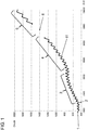
- the working process begins with the adjustment of the drive piston from its starting position at the beginning 1 of the pressure curve, represented as curve 11 and representing the course of the hydraulic pressure when a rivet is set.
- the rivet to be set by the working piston comes into contact with the components to be riveted at the course point 2 after the free travel has ended.
- the hydraulic pressure then increases during the penetration phase 3 of the rivet into the components.
- the penetration phase 3 is followed by the deformation phase 4 of the rivet, which is completed at the setting point 6, with a further increase in the hydraulic pressure.
- An adjustment 5 going beyond the setting point represents the pressure curve of the hydraulic pressure when the piston moves to a block, as a result of which the rivet connection would be destroyed and the components to be connected damaged.
- the control unit of the hydraulic tool detects the curve 11 of the pressure curve and continuously monitors this for the presence of the curve section in the setting point 6. If the control unit detects that the curve 11 of the pressure curve coincides with the curve section stored for the setting point 6, the setting process, e.g. by interrupting the drive of the pneumatic unit.
- the parameters of the pressure curve used to compare the recorded pressure curve with the stored pressure curve can be freely selected. For example, these can follow a pressure surge by comparing the maxima 7, the minima 8 and / or the reversal points 9 (cf. Figure 2 ). Both the time difference between the curve characteristics of adjacent pressure surges and the pressure difference of adjacent pressure surges can be used for the assessment.
- the slope 10a, 10b resulting from the maxima of the pressure surges is recorded, which is compared with an slope of the stored pressure curve (cf. Figure 3 ).
Landscapes
- Engineering & Computer Science (AREA)
- Mechanical Engineering (AREA)
- Fluid-Pressure Circuits (AREA)
- Insertion Pins And Rivets (AREA)
Applications Claiming Priority (1)
| Application Number | Priority Date | Filing Date | Title |
|---|---|---|---|
| DE102018132914.8A DE102018132914A1 (de) | 2018-12-19 | 2018-12-19 | Hydraulikwerkzeug sowie Verfahren zur automatischen Steuerung von pneumatisch angetriebenen Hydraulikwerkzeugen |
Publications (3)
| Publication Number | Publication Date |
|---|---|
| EP3670022A1 true EP3670022A1 (fr) | 2020-06-24 |
| EP3670022C0 EP3670022C0 (fr) | 2023-08-30 |
| EP3670022B1 EP3670022B1 (fr) | 2023-08-30 |
Family
ID=68654411
Family Applications (1)
| Application Number | Title | Priority Date | Filing Date |
|---|---|---|---|
| EP19210991.6A Active EP3670022B1 (fr) | 2018-12-19 | 2019-11-22 | Outil hydraulique de rivetage ainsi que procédé de commande automatique des outils hydrauliques de rivetage à entraînement pneumatique |
Country Status (2)
| Country | Link |
|---|---|
| EP (1) | EP3670022B1 (fr) |
| DE (1) | DE102018132914A1 (fr) |
Citations (5)
| Publication number | Priority date | Publication date | Assignee | Title |
|---|---|---|---|---|
| GB1157231A (en) * | 1967-02-28 | 1969-07-02 | Skyhi Ltd | Hydraulic and Pneumatic System for Controlling Tools |
| EP0062206A2 (fr) * | 1981-03-31 | 1982-10-13 | GESIPA Blindniettechnik Gesellschaft mit beschränkter Haftung | Dispositif pneumatique-hydraulique pour la pose de rivets aveugles |
| EP1738845A2 (fr) * | 2005-06-27 | 2007-01-03 | MS Gerätebau GmbH | Appareil de rivetage modulaire |
| CN104550618B (zh) * | 2015-01-29 | 2016-08-24 | 华东交通大学 | 一种气液增压自冲铆接机 |
| EP3293400A1 (fr) * | 2016-09-08 | 2018-03-14 | TKR Spezialwerkzeuge GmbH | Unité stationnaire d'alimentation pour outils hydrauliques |
Family Cites Families (4)
| Publication number | Priority date | Publication date | Assignee | Title |
|---|---|---|---|---|
| CN101890472B (zh) * | 2009-05-22 | 2012-11-28 | 中国气动工业股份有限公司 | 拉钉、拉帽枪的数字显示模组装置 |
| DE102012009729A1 (de) * | 2012-05-15 | 2013-11-21 | Robert Bosch Gmbh | Druck-Förderstromregler, Verstelleinheit für eine verstellbare hydraulische Verdrängermaschine mit einem Druck- Förderstromregler und Verfahren zum Regeln einer derartigen Verstelleinheit |
| DE102015004811B4 (de) * | 2015-04-14 | 2017-02-16 | Thomas Magnete Gmbh | Hydraulisch-pneumatische Vorrichtung zum Impulsfügen |
| CN110023004A (zh) * | 2016-09-30 | 2019-07-16 | 艾沛克斯品牌公司 | 便携式液压动力工具 |
-
2018
- 2018-12-19 DE DE102018132914.8A patent/DE102018132914A1/de not_active Ceased
-
2019
- 2019-11-22 EP EP19210991.6A patent/EP3670022B1/fr active Active
Patent Citations (5)
| Publication number | Priority date | Publication date | Assignee | Title |
|---|---|---|---|---|
| GB1157231A (en) * | 1967-02-28 | 1969-07-02 | Skyhi Ltd | Hydraulic and Pneumatic System for Controlling Tools |
| EP0062206A2 (fr) * | 1981-03-31 | 1982-10-13 | GESIPA Blindniettechnik Gesellschaft mit beschränkter Haftung | Dispositif pneumatique-hydraulique pour la pose de rivets aveugles |
| EP1738845A2 (fr) * | 2005-06-27 | 2007-01-03 | MS Gerätebau GmbH | Appareil de rivetage modulaire |
| CN104550618B (zh) * | 2015-01-29 | 2016-08-24 | 华东交通大学 | 一种气液增压自冲铆接机 |
| EP3293400A1 (fr) * | 2016-09-08 | 2018-03-14 | TKR Spezialwerkzeuge GmbH | Unité stationnaire d'alimentation pour outils hydrauliques |
Also Published As
| Publication number | Publication date |
|---|---|
| EP3670022C0 (fr) | 2023-08-30 |
| DE102018132914A1 (de) | 2020-06-25 |
| EP3670022B1 (fr) | 2023-08-30 |
Similar Documents
| Publication | Publication Date | Title |
|---|---|---|
| DE19705462C2 (de) | Verfahren zum Betreiben einer Elektropresse | |
| EP3378581B1 (fr) | Dispositif d'assemblage en plusieurs étapes et procédé d'assemblage correspondant | |
| DE102007059422B4 (de) | Verfahren zum Setzen von Nietelementen durch ein von einem Elektromotor angetriebenes portables Nietgerät sowie ein Nietgerät | |
| DE69317303T2 (de) | Selbststanzende nieten | |
| DE60306270T2 (de) | Verfahren und Vorrichtung zur Überwachung des Setzens von Blindnieten | |
| DE10324094B3 (de) | Verfahren zum Verschweißen von Teilen | |
| DE102004012294B4 (de) | Hochgeschwindigkeitsantriebsverfahren und -system für Druckzylinder | |
| EP3151987B1 (fr) | Presse radiale | |
| DE102016007951B4 (de) | Verfahren und Vorrichtung zur Kühlmittelversorgung spanender Werkzeuge | |
| EP0585589B1 (fr) | Procédé pour l'optimisation de processus d'emboutissage automatique et itératif aux presses | |
| EP2998029B1 (fr) | Procede d'application automatique d'un milieu liquide ou visqueux sur des composants et dispositif de dosage destine a executer le procede | |
| EP1064111A1 (fr) | Procede permettant de commander, de surveiller et de controler une operation de formage d'une machine de formage, notamment d'une riveteuse | |
| DE102021206492B4 (de) | Prozessventilvorrichtung und Verfahren | |
| EP3727830A1 (fr) | Dispositif et procédé de surveillance d'un outil d'entraînement de clavette | |
| EP3670022B1 (fr) | Outil hydraulique de rivetage ainsi que procédé de commande automatique des outils hydrauliques de rivetage à entraînement pneumatique | |
| EP3680050A2 (fr) | Procédé de vérification d'une pince à souder permettant le soudage par résistance de pièces à usiner | |
| EP4219942B1 (fr) | Pompe à piston à double effet et système d'application pour appliquer un fluide sur un substrat | |
| DE102004002593A1 (de) | Kontrollverfahren | |
| DE102004007056B4 (de) | Verfahren und Vorrichtung zur Herstellung eines umfänglich geschlossenen Hohlprofils | |
| EP2875962B1 (fr) | Procédé de fabrication d'une ligne de fabrication de livre | |
| EP1507182A1 (fr) | Procédé de déterminer l'usure pour des extrudeuses | |
| EP4144456B1 (fr) | Procédé de fabrication d'une conduite hydraulique à haute pression | |
| DE102005033786B3 (de) | Elektropneumatische Druckmittelmengensteuerung | |
| DE102006041222A1 (de) | Verfahren zum Freiformschmieden eines Werkstücks und Schmiedepresse | |
| DE102018214070B4 (de) | Verfahren und Vorrichtung zum Auftragen mittel- bis hochviskoser Materialien |
Legal Events
| Date | Code | Title | Description |
|---|---|---|---|
| PUAI | Public reference made under article 153(3) epc to a published international application that has entered the european phase |
Free format text: ORIGINAL CODE: 0009012 |
|
| STAA | Information on the status of an ep patent application or granted ep patent |
Free format text: STATUS: THE APPLICATION HAS BEEN PUBLISHED |
|
| AK | Designated contracting states |
Kind code of ref document: A1 Designated state(s): AL AT BE BG CH CY CZ DE DK EE ES FI FR GB GR HR HU IE IS IT LI LT LU LV MC MK MT NL NO PL PT RO RS SE SI SK SM TR |
|
| AX | Request for extension of the european patent |
Extension state: BA ME |
|
| STAA | Information on the status of an ep patent application or granted ep patent |
Free format text: STATUS: REQUEST FOR EXAMINATION WAS MADE |
|
| 17P | Request for examination filed |
Effective date: 20201030 |
|
| RBV | Designated contracting states (corrected) |
Designated state(s): AL AT BE BG CH CY CZ DE DK EE ES FI FR GB GR HR HU IE IS IT LI LT LU LV MC MK MT NL NO PL PT RO RS SE SI SK SM TR |
|
| GRAP | Despatch of communication of intention to grant a patent |
Free format text: ORIGINAL CODE: EPIDOSNIGR1 |
|
| STAA | Information on the status of an ep patent application or granted ep patent |
Free format text: STATUS: GRANT OF PATENT IS INTENDED |
|
| INTG | Intention to grant announced |
Effective date: 20230428 |
|
| GRAS | Grant fee paid |
Free format text: ORIGINAL CODE: EPIDOSNIGR3 |
|
| GRAA | (expected) grant |
Free format text: ORIGINAL CODE: 0009210 |
|
| STAA | Information on the status of an ep patent application or granted ep patent |
Free format text: STATUS: THE PATENT HAS BEEN GRANTED |
|
| AK | Designated contracting states |
Kind code of ref document: B1 Designated state(s): AL AT BE BG CH CY CZ DE DK EE ES FI FR GB GR HR HU IE IS IT LI LT LU LV MC MK MT NL NO PL PT RO RS SE SI SK SM TR |
|
| REG | Reference to a national code |
Ref country code: GB Ref legal event code: FG4D Free format text: NOT ENGLISH |
|
| REG | Reference to a national code |
Ref country code: CH Ref legal event code: EP |
|
| REG | Reference to a national code |
Ref country code: DE Ref legal event code: R096 Ref document number: 502019009126 Country of ref document: DE |
|
| REG | Reference to a national code |
Ref country code: IE Ref legal event code: FG4D Free format text: LANGUAGE OF EP DOCUMENT: GERMAN |
|
| U01 | Request for unitary effect filed |
Effective date: 20230830 |
|
| U07 | Unitary effect registered |
Designated state(s): AT BE BG DE DK EE FI FR IT LT LU LV MT NL PT SE SI Effective date: 20230905 |
|
| U20 | Renewal fee for the european patent with unitary effect paid |
Year of fee payment: 5 Effective date: 20231124 |
|
| PG25 | Lapsed in a contracting state [announced via postgrant information from national office to epo] |
Ref country code: GR Free format text: LAPSE BECAUSE OF FAILURE TO SUBMIT A TRANSLATION OF THE DESCRIPTION OR TO PAY THE FEE WITHIN THE PRESCRIBED TIME-LIMIT Effective date: 20231201 |
|
| PG25 | Lapsed in a contracting state [announced via postgrant information from national office to epo] |
Ref country code: IS Free format text: LAPSE BECAUSE OF FAILURE TO SUBMIT A TRANSLATION OF THE DESCRIPTION OR TO PAY THE FEE WITHIN THE PRESCRIBED TIME-LIMIT Effective date: 20231230 |
|
| PG25 | Lapsed in a contracting state [announced via postgrant information from national office to epo] |
Ref country code: RS Free format text: LAPSE BECAUSE OF FAILURE TO SUBMIT A TRANSLATION OF THE DESCRIPTION OR TO PAY THE FEE WITHIN THE PRESCRIBED TIME-LIMIT Effective date: 20230830 Ref country code: NO Free format text: LAPSE BECAUSE OF FAILURE TO SUBMIT A TRANSLATION OF THE DESCRIPTION OR TO PAY THE FEE WITHIN THE PRESCRIBED TIME-LIMIT Effective date: 20231130 Ref country code: IS Free format text: LAPSE BECAUSE OF FAILURE TO SUBMIT A TRANSLATION OF THE DESCRIPTION OR TO PAY THE FEE WITHIN THE PRESCRIBED TIME-LIMIT Effective date: 20231230 Ref country code: HR Free format text: LAPSE BECAUSE OF FAILURE TO SUBMIT A TRANSLATION OF THE DESCRIPTION OR TO PAY THE FEE WITHIN THE PRESCRIBED TIME-LIMIT Effective date: 20230830 Ref country code: GR Free format text: LAPSE BECAUSE OF FAILURE TO SUBMIT A TRANSLATION OF THE DESCRIPTION OR TO PAY THE FEE WITHIN THE PRESCRIBED TIME-LIMIT Effective date: 20231201 |
|
| PG25 | Lapsed in a contracting state [announced via postgrant information from national office to epo] |
Ref country code: PL Free format text: LAPSE BECAUSE OF FAILURE TO SUBMIT A TRANSLATION OF THE DESCRIPTION OR TO PAY THE FEE WITHIN THE PRESCRIBED TIME-LIMIT Effective date: 20230830 |
|
| PG25 | Lapsed in a contracting state [announced via postgrant information from national office to epo] |
Ref country code: ES Free format text: LAPSE BECAUSE OF FAILURE TO SUBMIT A TRANSLATION OF THE DESCRIPTION OR TO PAY THE FEE WITHIN THE PRESCRIBED TIME-LIMIT Effective date: 20230830 |
|
| PG25 | Lapsed in a contracting state [announced via postgrant information from national office to epo] |
Ref country code: SM Free format text: LAPSE BECAUSE OF FAILURE TO SUBMIT A TRANSLATION OF THE DESCRIPTION OR TO PAY THE FEE WITHIN THE PRESCRIBED TIME-LIMIT Effective date: 20230830 Ref country code: RO Free format text: LAPSE BECAUSE OF FAILURE TO SUBMIT A TRANSLATION OF THE DESCRIPTION OR TO PAY THE FEE WITHIN THE PRESCRIBED TIME-LIMIT Effective date: 20230830 Ref country code: ES Free format text: LAPSE BECAUSE OF FAILURE TO SUBMIT A TRANSLATION OF THE DESCRIPTION OR TO PAY THE FEE WITHIN THE PRESCRIBED TIME-LIMIT Effective date: 20230830 Ref country code: CZ Free format text: LAPSE BECAUSE OF FAILURE TO SUBMIT A TRANSLATION OF THE DESCRIPTION OR TO PAY THE FEE WITHIN THE PRESCRIBED TIME-LIMIT Effective date: 20230830 Ref country code: SK Free format text: LAPSE BECAUSE OF FAILURE TO SUBMIT A TRANSLATION OF THE DESCRIPTION OR TO PAY THE FEE WITHIN THE PRESCRIBED TIME-LIMIT Effective date: 20230830 |
|
| REG | Reference to a national code |
Ref country code: DE Ref legal event code: R097 Ref document number: 502019009126 Country of ref document: DE |
|
| REG | Reference to a national code |
Ref country code: CH Ref legal event code: PL |
|
| PG25 | Lapsed in a contracting state [announced via postgrant information from national office to epo] |
Ref country code: MC Free format text: LAPSE BECAUSE OF FAILURE TO SUBMIT A TRANSLATION OF THE DESCRIPTION OR TO PAY THE FEE WITHIN THE PRESCRIBED TIME-LIMIT Effective date: 20230830 |
|
| PLBE | No opposition filed within time limit |
Free format text: ORIGINAL CODE: 0009261 |
|
| STAA | Information on the status of an ep patent application or granted ep patent |
Free format text: STATUS: NO OPPOSITION FILED WITHIN TIME LIMIT |
|
| PG25 | Lapsed in a contracting state [announced via postgrant information from national office to epo] |
Ref country code: CH Free format text: LAPSE BECAUSE OF NON-PAYMENT OF DUE FEES Effective date: 20231130 |
|
| PG25 | Lapsed in a contracting state [announced via postgrant information from national office to epo] |
Ref country code: MC Free format text: LAPSE BECAUSE OF FAILURE TO SUBMIT A TRANSLATION OF THE DESCRIPTION OR TO PAY THE FEE WITHIN THE PRESCRIBED TIME-LIMIT Effective date: 20230830 Ref country code: CH Free format text: LAPSE BECAUSE OF NON-PAYMENT OF DUE FEES Effective date: 20231130 |
|
| 26N | No opposition filed |
Effective date: 20240603 |
|
| REG | Reference to a national code |
Ref country code: IE Ref legal event code: MM4A |
|
| PG25 | Lapsed in a contracting state [announced via postgrant information from national office to epo] |
Ref country code: IE Free format text: LAPSE BECAUSE OF NON-PAYMENT OF DUE FEES Effective date: 20231122 |
|
| PG25 | Lapsed in a contracting state [announced via postgrant information from national office to epo] |
Ref country code: IE Free format text: LAPSE BECAUSE OF NON-PAYMENT OF DUE FEES Effective date: 20231122 |
|
| U20 | Renewal fee for the european patent with unitary effect paid |
Year of fee payment: 6 Effective date: 20241125 |
|
| PG25 | Lapsed in a contracting state [announced via postgrant information from national office to epo] |
Ref country code: CY Free format text: LAPSE BECAUSE OF FAILURE TO SUBMIT A TRANSLATION OF THE DESCRIPTION OR TO PAY THE FEE WITHIN THE PRESCRIBED TIME-LIMIT; INVALID AB INITIO Effective date: 20191122 |
|
| PG25 | Lapsed in a contracting state [announced via postgrant information from national office to epo] |
Ref country code: HU Free format text: LAPSE BECAUSE OF FAILURE TO SUBMIT A TRANSLATION OF THE DESCRIPTION OR TO PAY THE FEE WITHIN THE PRESCRIBED TIME-LIMIT; INVALID AB INITIO Effective date: 20191122 |
|
| PG25 | Lapsed in a contracting state [announced via postgrant information from national office to epo] |
Ref country code: TR Free format text: LAPSE BECAUSE OF FAILURE TO SUBMIT A TRANSLATION OF THE DESCRIPTION OR TO PAY THE FEE WITHIN THE PRESCRIBED TIME-LIMIT Effective date: 20230830 |
|
| U20 | Renewal fee for the european patent with unitary effect paid |
Year of fee payment: 7 Effective date: 20251117 |
|
| PGFP | Annual fee paid to national office [announced via postgrant information from national office to epo] |
Ref country code: GB Payment date: 20251120 Year of fee payment: 7 |