EP3670188B1 - Procédé de détection de défaillances de buse dans une tête d'impression à jet d'encre - Google Patents
Procédé de détection de défaillances de buse dans une tête d'impression à jet d'encre Download PDFInfo
- Publication number
- EP3670188B1 EP3670188B1 EP18213423.9A EP18213423A EP3670188B1 EP 3670188 B1 EP3670188 B1 EP 3670188B1 EP 18213423 A EP18213423 A EP 18213423A EP 3670188 B1 EP3670188 B1 EP 3670188B1
- Authority
- EP
- European Patent Office
- Prior art keywords
- liquid
- print job
- ejection unit
- printing
- ejection
- Prior art date
- Legal status (The legal status is an assumption and is not a legal conclusion. Google has not performed a legal analysis and makes no representation as to the accuracy of the status listed.)
- Active
Links
Images


Classifications
-
- B—PERFORMING OPERATIONS; TRANSPORTING
- B41—PRINTING; LINING MACHINES; TYPEWRITERS; STAMPS
- B41J—TYPEWRITERS; SELECTIVE PRINTING MECHANISMS, i.e. MECHANISMS PRINTING OTHERWISE THAN FROM A FORME; CORRECTION OF TYPOGRAPHICAL ERRORS
- B41J2/00—Typewriters or selective printing mechanisms characterised by the printing or marking process for which they are designed
- B41J2/005—Typewriters or selective printing mechanisms characterised by the printing or marking process for which they are designed characterised by bringing liquid or particles selectively into contact with a printing material
- B41J2/01—Ink jet
- B41J2/135—Nozzles
- B41J2/14—Structure thereof only for on-demand ink jet heads
- B41J2/14201—Structure of print heads with piezoelectric elements
- B41J2/14233—Structure of print heads with piezoelectric elements of film type, deformed by bending and disposed on a diaphragm
-
- B—PERFORMING OPERATIONS; TRANSPORTING
- B41—PRINTING; LINING MACHINES; TYPEWRITERS; STAMPS
- B41J—TYPEWRITERS; SELECTIVE PRINTING MECHANISMS, i.e. MECHANISMS PRINTING OTHERWISE THAN FROM A FORME; CORRECTION OF TYPOGRAPHICAL ERRORS
- B41J2/00—Typewriters or selective printing mechanisms characterised by the printing or marking process for which they are designed
- B41J2/005—Typewriters or selective printing mechanisms characterised by the printing or marking process for which they are designed characterised by bringing liquid or particles selectively into contact with a printing material
- B41J2/01—Ink jet
- B41J2/015—Ink jet characterised by the jet generation process
- B41J2/04—Ink jet characterised by the jet generation process generating single droplets or particles on demand
- B41J2/045—Ink jet characterised by the jet generation process generating single droplets or particles on demand by pressure, e.g. electromechanical transducers
- B41J2/04501—Control methods or devices therefor, e.g. driver circuits, control circuits
- B41J2/0451—Control methods or devices therefor, e.g. driver circuits, control circuits for detecting failure, e.g. clogging, malfunctioning actuator
-
- B—PERFORMING OPERATIONS; TRANSPORTING
- B41—PRINTING; LINING MACHINES; TYPEWRITERS; STAMPS
- B41J—TYPEWRITERS; SELECTIVE PRINTING MECHANISMS, i.e. MECHANISMS PRINTING OTHERWISE THAN FROM A FORME; CORRECTION OF TYPOGRAPHICAL ERRORS
- B41J2/00—Typewriters or selective printing mechanisms characterised by the printing or marking process for which they are designed
- B41J2/005—Typewriters or selective printing mechanisms characterised by the printing or marking process for which they are designed characterised by bringing liquid or particles selectively into contact with a printing material
- B41J2/01—Ink jet
- B41J2/015—Ink jet characterised by the jet generation process
- B41J2/04—Ink jet characterised by the jet generation process generating single droplets or particles on demand
- B41J2/045—Ink jet characterised by the jet generation process generating single droplets or particles on demand by pressure, e.g. electromechanical transducers
- B41J2/04501—Control methods or devices therefor, e.g. driver circuits, control circuits
- B41J2/04571—Control methods or devices therefor, e.g. driver circuits, control circuits detecting viscosity
-
- B—PERFORMING OPERATIONS; TRANSPORTING
- B41—PRINTING; LINING MACHINES; TYPEWRITERS; STAMPS
- B41J—TYPEWRITERS; SELECTIVE PRINTING MECHANISMS, i.e. MECHANISMS PRINTING OTHERWISE THAN FROM A FORME; CORRECTION OF TYPOGRAPHICAL ERRORS
- B41J2/00—Typewriters or selective printing mechanisms characterised by the printing or marking process for which they are designed
- B41J2/005—Typewriters or selective printing mechanisms characterised by the printing or marking process for which they are designed characterised by bringing liquid or particles selectively into contact with a printing material
- B41J2/01—Ink jet
- B41J2/015—Ink jet characterised by the jet generation process
- B41J2/04—Ink jet characterised by the jet generation process generating single droplets or particles on demand
- B41J2/045—Ink jet characterised by the jet generation process generating single droplets or particles on demand by pressure, e.g. electromechanical transducers
- B41J2/04501—Control methods or devices therefor, e.g. driver circuits, control circuits
- B41J2/04581—Control methods or devices therefor, e.g. driver circuits, control circuits controlling heads based on piezoelectric elements
-
- B—PERFORMING OPERATIONS; TRANSPORTING
- B41—PRINTING; LINING MACHINES; TYPEWRITERS; STAMPS
- B41J—TYPEWRITERS; SELECTIVE PRINTING MECHANISMS, i.e. MECHANISMS PRINTING OTHERWISE THAN FROM A FORME; CORRECTION OF TYPOGRAPHICAL ERRORS
- B41J2/00—Typewriters or selective printing mechanisms characterised by the printing or marking process for which they are designed
- B41J2/005—Typewriters or selective printing mechanisms characterised by the printing or marking process for which they are designed characterised by bringing liquid or particles selectively into contact with a printing material
- B41J2/01—Ink jet
- B41J2/135—Nozzles
- B41J2/165—Prevention or detection of nozzle clogging, e.g. cleaning, capping or moistening for nozzles
- B41J2/16579—Detection means therefor, e.g. for nozzle clogging
-
- B—PERFORMING OPERATIONS; TRANSPORTING
- B41—PRINTING; LINING MACHINES; TYPEWRITERS; STAMPS
- B41J—TYPEWRITERS; SELECTIVE PRINTING MECHANISMS, i.e. MECHANISMS PRINTING OTHERWISE THAN FROM A FORME; CORRECTION OF TYPOGRAPHICAL ERRORS
- B41J2/00—Typewriters or selective printing mechanisms characterised by the printing or marking process for which they are designed
- B41J2/005—Typewriters or selective printing mechanisms characterised by the printing or marking process for which they are designed characterised by bringing liquid or particles selectively into contact with a printing material
- B41J2/01—Ink jet
- B41J2/21—Ink jet for multi-colour printing
- B41J2/2132—Print quality control characterised by dot disposition, e.g. for reducing white stripes or banding
- B41J2/2142—Detection of malfunctioning nozzles
-
- B—PERFORMING OPERATIONS; TRANSPORTING
- B41—PRINTING; LINING MACHINES; TYPEWRITERS; STAMPS
- B41J—TYPEWRITERS; SELECTIVE PRINTING MECHANISMS, i.e. MECHANISMS PRINTING OTHERWISE THAN FROM A FORME; CORRECTION OF TYPOGRAPHICAL ERRORS
- B41J2/00—Typewriters or selective printing mechanisms characterised by the printing or marking process for which they are designed
- B41J2/005—Typewriters or selective printing mechanisms characterised by the printing or marking process for which they are designed characterised by bringing liquid or particles selectively into contact with a printing material
- B41J2/01—Ink jet
- B41J2/135—Nozzles
- B41J2/14—Structure thereof only for on-demand ink jet heads
- B41J2002/14354—Sensor in each pressure chamber
Definitions
- the present invention generally pertains to detecting nozzle failures in an inkjet print head.
- a piezo-actuator for generating a pressure wave in a pressure chamber of an inkjet print head such that a droplet of liquid, usually ink, is expelled through a nozzle, which nozzle is in fluid communication with the pressure chamber.
- the piezo-actuator (or an additional piezo-element or a dedicated part of the piezo-actuator) may be used to detect a pressure wave in the pressure chamber. For example, after actuation, a residual pressure wave remains in the pressure chamber and the residual pressure wave may be detected using the piezo-actuator. Said residual pressure wave is usually analyzed, such that it is possible to infer from it whether the inkjet print head is working correctly.
- the inkjet print head In the case where the inkjet print head is not working correctly, it is possible to infer, with different degrees of reliability, what the cause of the malfunctioning is: presence of an air bubble; presence of dust; too viscous ink, etc.
- the known methods based on the analysis of residual pressure waves are however incapable of reliable determining the cause of nozzle failures, and may sometimes even lead to a non-negligible amount of both false positives (concluding that a nozzle is failing when it is working correctly) and false negatives (concluding that a nozzle is working correctly when it is not jetting appropriately). Further, the accuracy of the known methods based on analyzing the residual pressure wave often diminishes as the print head ages.
- Document US 2013/0141484 A1 relates to a liquid ejection device including a head, a first sensor, a second sensor, a recovery unit, and a controller.
- the head is configured to eject liquid on a medium.
- the first sensor is configured to detect liquid ejection of the head by using a first principle.
- the second sensor is configured to detect the liquid ejection by using a second principle being different from the first principle.
- the recovery unit is configured to recover the liquid ejection of the head.
- the controller is configured to control the first sensor and the second sensor, and control the recovery unit based on a first detection result by the first sensor and a second detection result by the second detector.
- a method of operating a droplet ejection device according to claim 1 is provided.
- a droplet ejection device and a printing system according to claims 7 and 8 are provided.
- the present invention comprises a software product according to claim 9.
- the present invention comprises a method for detecting an operating state of an ejection unit during the printing of an object of a print job comprising one or more objects, wherein the ejection unit is arranged to eject droplets of a liquid and comprises a nozzle, in particular a plurality of nozzles; a liquid duct connected to the nozzle; and an electro-mechanical transducer arranged to create an acoustic pressure wave in the liquid in the duct.
- the present invention comprises actuating the electro-mechanical transducer to generate a pressure wave in the liquid.
- the pressure wave generated in the liquid generates, as is known in the art, a residual pressure wave in the liquid.
- At least one parameter may be inferred or generated based upon the residual pressure wave that is sensed.
- the ejection unit can be determined by comparing the at least one parameter generated based upon the residual pressure wave with at least one threshold, whether the ejection unit is in an operative state or in a malfunctioning state.
- the printing take place by ejecting droplets of liquid from the plurality of nozzles onto the recording medium in accordance with the print job.
- the ejected droplets should be in accordance with the print job data.
- an additional check of the operational state the ejection unit to determine whether it is in an operative state or in a malfunctioning state by scanning a location of the recording medium onto which droplets of liquid from the plurality of nozzles have been ejected, thereby providing a scanned image, wherein scanning a location of the recording medium is performed every one or more objects of the print job. Once the scanned image is analyzed it can be determined based on the scanning whether the ejection unit is in an operative state or in a malfunctioning state.
- the accuracy of the determination based on an analysis of parameters determined from a residual pressure wave is smaller than that by scanning the result of the actual ejections.
- the determinations of the operative state of the ejection unit determine a different operative state, the operative state is considered to be that determined by scanning the locations of the recording medium onto which liquid has been ejected.
- providing feedback about the determined state of the ejection unit by scanning the droplets ejected onto the recording medium comprises storing the at least one parameter generated from the residual pressure wave, and comprises determining during the printing of a second object of a print job that the ejection unit is in the same state determined during the printing of an object of a print job by scanning the droplets ejected onto the recording medium if the at least one parameter measured are similar during the printing of a second object of the print job.
- providing feedback about the determined state of the ejection unit about the determined state of the ejection unit by scanning the droplets ejected onto the recording medium comprises modifying the thresholds to be used when determining the operative state of the ejection unit by analyzing the residual pressure wave during the printing of subsequent objects of a print job.
- the method of the present invention further comprises reducing the number of objects of the print job comprising a plurality of objects for which the scanning a location of the recording medium is performed if both determinations of the operative state of the ejection unit yield the same result during the printing of one or more consecutive objects of the print job.
- the step of determining the operative state of an ejection unit by analyzing parameters of a residual pressure wave further comprises assigning a reliability assessment factor and an ejection failure cause to the determination when it is determined that the ejection unit is in an operative state or in a malfunctioning state.
- the assignation of a reliability factor under a threshold when determining the operative state of an ejection unit by analyzing parameters of a residual pressure wave triggers the scanning a location of the recording medium onto which droplets of liquid from the plurality of nozzles have been ejected during the execution of the method on the same object of the assignation.
- the assignation of a reliability assessment factor under a threshold of 0.8 may trigger the scanning during the printing of the object that led to such determination in order to increase the correctness of future determinations.
- the present invention comprises a droplet ejection device comprising a number of ejection units arranged to eject droplets of a liquid and each comprising a nozzle, a liquid duct connected to the nozzle, and an electro-mechanical transducer arranged to create an acoustic pressure wave in the liquid in the duct, wherein each of the ejection units is arranged to perform any of the methods of the present invention.
- the present invention comprises a printing system comprising the droplet ejection device of the present invention as an ink jet print head.
- the present invention comprises a software product comprising program code on a machine-readable non transitory medium, the program code, when loaded into a control unit of a printing system according to the present invention, causes the control unit to execute any of the methods of the present invention.
- Step S1 an actuation is made on an ejection unit, thereby causing the ejection of droplets of liquid onto a recording medium.
- this step may take place during the printing of a print job, or during the execution of a calibration procedure.
- step S2 it is determined whether the ejection unit is operating correctly based on an analysis of the residual pressure wave generated by the actuation. Further, it may also be determined what the cause of the malfunction is, in case the ejection unit is not operating correctly.
- step S3 an additional determination is made whether the ejection unit is operating correctly based on scanning the recording medium with an image based sensor or scanner.
- a final step S4 the results provided by steps S2 and S3 are compared with each other and a final determination is made on the operative state of the ejection unit. Subsequently, when the process takes place during the printing of a print job the known methods proceed to repeat the process for the following ejections until the print job is finished.
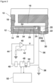
- FIG. 2 A single ejection unit of an ink jet print head has been shown in Fig. 2 .
- the print head constitutes an example of a droplet ejection device according to the invention.
- the device comprises a wafer 10 and a support member 12 that are bonded to opposite sides of a thin flexible membrane 14.
- a recess that forms an ink duct 16 is formed in the face of the wafer 10 that engages the membrane 14, e.g. the bottom face in Fig. 2 .
- the ink duct 16 has an essentially rectangular shape.
- An end portion on the left side in Fig. 2 is connected to an ink supply line 18 that passes through the wafer 10 in thickness direction of the wafer and serves for supplying liquid ink to the ink duct 16.
- An opposite end of the ink duct 16, on the right side in Fig. 2 is connected, through an opening in the membrane 14, to a chamber 20 that is formed in the support member 12 and opens out into a nozzle 22 that is formed in a nozzle face 24 constituting the bottom face of the support member.
- the support member 12 Adjacent to the membrane 14 and separated from the chamber 20, the support member 12 forms another cavity 26 accommodating a piezoelectric actuator 28 that is bonded to the membrane 14.
- An ink supply system which has not been shown here keeps the pressure of the liquid ink in the ink duct 16 slightly below the atmospheric pressure, so as to prevent the ink from leaking out through the nozzle 22.
- the nozzle face 24 is made of or coated with a material which is wetted by the ink, so that adhesion forces cause a pool 30 of ink to be formed on the nozzle face 24 around the nozzle 22.
- the pool 30 is delimited on the outward (bottom) side by a meniscus 32a.
- the piezoelectric transducer 28 has electrodes 34 that are connected to an electronic circuit that has been shown in the lower part of Fig. 2 .
- one electrode of the transducer is grounded via a line 36 and a resistor 38.
- Another electrode of the transducer is connected to an output of an amplifier 40 that is feedbackcontrolled via a feedback network 42, so that a voltage V applied to the transducer will be proportional to a signal on an input line 44 of the amplifier.
- the signal on the input line 44 is generated by a D/A-converter 46 that receives a digital input from a local digital controller 48.
- the controller 48 is connected to a processor 50.
- the processor 50 sends a command to the controller 48 which outputs a digital signal that causes the D/A-converter 46 and the amplifier 40 to apply an actuation pulse to the transducer 28.
- This voltage pulse causes the transducer to deform in a bending mode. More specifically, the transducer 28 is caused to flex downward, so that the membrane 14 which is bonded to the transducer 28 will also flex downward, thereby to increase the volume of the ink duct 16. As a consequence, additional ink will be sucked-in via the supply line 18.
- the membrane 14 will flex back into the original state, so that a positive acoustic pressure wave is generated in the liquid ink in the duct 16.
- This pressure wave propagates to the nozzle 22 and causes an ink droplet to be expelled.
- the pressure wave will then be reflected at the meniscus 32a and will oscillate in the cavity formed between the meniscus and the left end of the duct 16 in Fig. 2 .
- the oscillation will be damped due to the viscosity of the ink.
- the transducer 28 is energized with a quench pulse which has a polarity opposite to that of the actuation pulse and is timed such that the decaying oscillation will be suppressed further by destructive interference.
- the electrodes 34 of the transducer 28 are also connected to an A/D converter 52 which measures a voltage drop across the transducer and also a voltage drop across the resistor 38 and thereby implicitly the current flowing through the transducer.
- Corresponding digital signals S are forwarded to the controller 48 which can derive the impedance of the transducer 28 from these signals.
- the measured electric response (current, voltage, impedance, etc.) is signaled to the processor 50 where the electric response is processed further.
- FIG. 3 A method according to the present invention for detecting an operating state of an ejection unit during the printing of an object is shown in Fig. 3 .
- the method may be executed in any ejection unit, as for example that described in relation to Fig. 2 .
- an object shall be understood as comprising any of the many instances in which printing techniques might be used: 2D printing of pages, banners, as well as 2.5D and 3D objects. It also refers to the printing off-line during maintenance actions.
- step S2 involves sensing the residual pressure wave in the liquid in the duct of the ejection unit, and subsequently performing step S3 in which at least one parameter is generated based upon the residual pressure wave sensed in step S2.
- a subsequent step S4 is executed, in which it is determined during the printing of every object of the print job, by comparing the at least one parameter generated in step S3 with at least one threshold, whether the ejection unit is in an operative state or in a malfunctioning state.
- the process of actuating the transducer in an ejection unit to generate a pressure wave, and subsequently sensing the residual pressure wave is known in the art. It is also known generating one or more parameters from the residual pressure wave sensed, such as amplitude, frequency, damping factor, etc. Said parameters may be determined by analyzing the residual pressure wave in the time domain as well as in the frequency domain. An example can be found in patent applications EP3150380 and PCT/2017/068721 in the name of Océ-Technologies B.V.
- step S4 further comprises assigning a reliability assessment factor and an ejection failure cause to the determination when it is determined that the ejection unit is in an operative state or in a malfunctioning state.
- This reliability assessment factor is based on knowledge developed during testing of the ejection units, and assigns a higher factor to those ejection failures which are known to lead lo a smaller number of false positives and negatives. For example, those reliability assessment factors related to problems in the ink duct of the ejection unit, such as presence of air or dust, are assigned a higher reliability assessment factor than those related to shooting angle deviations.
- Said reliability assessment factor may be a factor between 0 and 1, wherein a high reliability assessment factor indicates a high likelihood that the assessment performed by the method of the operative state of an ejection unit yields a correct result.
- a high reliability assessment factor indicates a high likelihood that the assessment performed by the method of the operative state of an ejection unit yields a correct result.
- the reliability assessment factor may optionally be determined by offline calibration procedures. Additionally, said reliability assessment factor may also be altered using the feedback provided by the present invention after scanning the droplets ejected onto a recording medium, if said scanning process proves that the reliability shown by the determinations is higher than the reliability assessment factor assigned.
- step S1 The actuation performed in step S1, which is performed such that the generated pressure wave is sufficient to operate the ejection unit, causes the ejection of droplets of liquid onto the recording medium in accordance with print job which is referred to in Fig. 3 as step S5.
- step S6 is performed which involves the scanning a location of the recording medium onto which droplets of liquid from the plurality of nozzles have been ejected. This process leads to a scanned image. Said scanning a location of the recording medium is performed every one or more objects of the print job.
- the method of the present invention further comprises reducing the number of objects of the print job comprising one or more objects for which the scanning a location of the recording medium is performed if both the determinations performed, the one based on analyzing the residual pressure wave and the one by scanning, yield the same result during the printing of one or more consecutive objects of the print job.
- the method of the present invention performs also both determinations in a subsequent iteration.
- the method of the present invention gradually reduces the number of iterations in which the scanning process is performed. In this way less processing is needed to improve the results of the determination based on analyzing the residual pressure wave.
- the assignation of a reliability factor under a threshold when determining the operative state of the ejection unit by analyzing the residual pressure wave triggers the scanning a location of the recording medium onto which droplets of liquid from the plurality of nozzles have been ejected during the execution of the method on the same objects of the assignation.
- the method of the present invention contemplates not performing said scanning for every object.
- the determination performed by analyzing the residual pressure wave shows a low reliability (for example, a side shooting nozzle) said scanning is trigger in the same iteration in order to improve the determination.
- step S6 the scanned image which results from step S6 is analyzed in step S7 in order to make an additional determination of the operative state of the ejection unit.
- step S8 of the state of the ejection unit by fusing the information provided by the determinations performed in steps S4 and S7.
- step S8 the determination of step S4 is overridden, and the final determination of the operative state is based on the result of the scanning process, which has a higher reliability.
- the method of the present invention provides feedback about the determined state of the ejection unit to be taken into account when determining the operative state of an ejection unit by analyzing the residual pressure wave during the printing of the subsequent objects of the print job.
- providing feedback may comprise storing and labelling the determinations performed about the operative state of the ejection unit based both in analyzing the residual pressure wave as well as analyzing the ejections onto a recording medium with an image sensor or scanner.
- the method of the present invention may comprise storing and labeling the residual pressure wave sensed in the liquid, as well as the at least one parameter generated therefrom.
- the method of the present invention may comprise storing and labelling the deviations in the ejections from the ejection unit detected by scanning with an image sensor or scanner.
- Optionally providing feedback about the determined state of the ejection unit by taking into account both determinations performed comprises storing the at least one parameter generated from the residual pressure wave, and further comprises determining during the printing of a subsequent object of a print job that the ejection unit is in the same state determined during printing by analyzing the scanned image if the difference between the at least one parameter measured during the printing of a second object of the print job and the at least one parameter generated based upon the sensed residual pressure wave is under a threshold.
- the method of the present invention may be executed, and it reaches a determination that the ejection unit has a shooting angle deviation problem, that is confirmed by a subsequent scanning step.
- the at least one parameter generated may be stored.
- the method of the present invention does not only store parameters but a complete residual pressure wave.
- statistical analysis may be performed between the residual pressure wave stored and the one generated in a subsequent iteration such that based on the statistical parameters inferred a determination may be made about whether the resemblance is high enough to determine the same cause of failure or the correctly functioning of an ejection unit.
- the present invention may take into account the complete residual pressure wave that was stored and labeled in previous iterations in order to perform a statistical analysis that allows improving the accuracy of subsequent determinations by analyzing the residual pressure wave.
- Providing feedback about the determined state of the ejection unit in by taking into account both previous determinations comprises modifying the thresholds to be used when determining the operative state of the ejection unit during the printing of subsequent objects of a print job. Due to different reasons, as for example aging of the ejection unit or of the liquid to be jetted, sometimes the parameters measured lead to consistent errors in the determinations performed by analyzing the residual pressure wave that can be remedied by altering slightly the thresholds used in the determinations.
- the data stored and labeled as feedback is used in the determinations performed by analyzing the residual pressure wave in order to improve the accuracy of the determinations.
- said determinations performed by analyzing the residual pressure wave when they are improved with said stored and labeled data, further generate labeled data that is also stored and labeled such that it can be used in subsequent iterations to further improve the result of the determinations.
Landscapes
- Engineering & Computer Science (AREA)
- Quality & Reliability (AREA)
- Ink Jet (AREA)
Claims (9)
- Procédé de détection d'un état de fonctionnement d'une unité d'éjection pendant l'impression d'un objet d'un travail d'impression comprenant un ou plusieurs objets, dans lequel l'unité d'éjection est conçue pour éjecter des gouttelettes d'un liquide et comprend une pluralité de buses (22), un conduit de liquide (16) relié à la buse (22), et un transducteur électromécanique (28) conçu pour créer une onde de pression acoustique dans le liquide dans le conduit (16), le procédé comprenant les étapes suivantes :a. actionner le transducteur électromécanique (22) pour générer une onde de pression dans le liquide ;b. la détection d'une onde de pression résiduelle dans le liquide ;c. générer au moins un paramètre basé sur l'onde de pression résiduelle détectée ;d. déterminer, en comparant l'au moins un paramètre généré à l'étape c. à au moins un seuil, si l'unité d'éjection est en état de fonctionnement ou en état de dysfonctionnement ;e. éjecter des gouttelettes de liquide de la pluralité de buses sur le support d'enregistrement conformément au travail d'impression ;f. la numérisation d'un emplacement du support d'enregistrement sur lequel des gouttelettes de liquide provenant de la pluralité de buses ont été éjectées, fournissant ainsi une image numérisée, la numérisation d'un emplacement du support d'enregistrement étant effectuée tous les un ou plusieurs objets du travail d'impression ;g. analyser l'image scannée à l'étape f. pour déterminer si l'unité d'éjection est en état de fonctionnement ou de dysfonctionnement ;h. si la détermination de l'étape d. et la détermination de l'étape g. ne donnent pas le même résultat, faire prévaloir le second et fournir un retour d'information sur l'état déterminé de l'unité d'éjection à prendre en compte à l'étape d. lors de l'impression des objets suivants du travail d'impression, le retour d'information consistant à modifier au moins un seuil à l'étape d. pour l'utiliser dans d'autres comparaisons ;i. en répétant les étapes de a. à h. jusqu'au dernier objet du travail d'impression.
- Procédé selon la revendication 1, dans lequel la fourniture d'un retour d'information sur l'état déterminé de l'unité d'éjection à l'étape h. comprend le stockage de l'au moins un paramètre généré à l'étape c., et comprend la détermination pendant l'impression d'un deuxième objet d'un travail d'impression que l'unité d'éjection est dans le même état déterminé pendant l'impression d'un objet d'un travail d'impression à l'étape g. si la différence entre l'au moins un paramètre mesuré pendant l'impression d'un deuxième objet du travail d'impression et l'au moins un paramètre généré à l'étape c. est inférieure à un seuil.
- Procédé selon la revendication 1, dans lequel la fourniture d'un retour d'information sur l'état déterminé de l'unité d'éjection à l'étape h. comprend la modification des seuils à utiliser à l'étape d. lors de l'impression des objets suivants d'un travail d'impression.
- Procédé selon l'une quelconque des revendications précédentes, comprenant en outre la réduction du nombre d'objets du travail d'impression comprenant un ou plusieurs objets pour lesquels le balayage d'un emplacement du support d'enregistrement de l'étape f. est effectué si les déterminations de l'étape d. et de l'étape g. donnent le même résultat lors de l'impression d'un ou de plusieurs objets consécutifs du travail d'impression.
- Procédé selon l'une quelconque des revendications précédentes, dans lequel l'étape d. consiste en outre à attribuer un facteur d'évaluation de la fiabilité et une cause de défaillance de l'éjection à la détermination lorsqu'il est déterminé que l'unité d'éjection est dans un état opérationnel ou dans un état de dysfonctionnement.
- Procédé selon la revendication 5, dans lequel l'attribution d'un facteur de fiabilité inférieur à un seuil à l'étape d. déclenche le balayage d'un emplacement du support d'enregistrement sur lequel des gouttelettes de liquide provenant de la pluralité de buses ont été éjectées de l'étape f. au cours de l'exécution du procédé sur les mêmes objets de l'attribution.
- Dispositif d'éjection de gouttelettes comprenant plusieurs unités d'éjection agencées pour éjecter des gouttelettes d'un liquide et comprenant chacune une buse (22), un conduit de liquide (16) relié à la buse (22), et un transducteur électromécanique (28) agencé pour créer une onde de pression acoustique dans le liquide dans le conduit (16), caractérisé en ce que chacune des unités d'éjection est associée à un processeur (50) configuré pour mettre en œuvre un procédé selon l'une quelconque des revendications 1 à 6.
- Système d'impression comprenant le dispositif d'éjection de gouttelettes selon la revendication 7 en tant que tête d'impression à jet d'encre et une unité de commande adaptée à l'exécution d'un procédé selon l'une quelconque des revendications 1 à 6.
- Produit logiciel comprenant un code de programme sur un support non transitoire lisible par une machine, le code de programme, lorsqu'il est chargé dans une unité de commande d'un système d'impression selon la revendication 8, amène l'unité de commande à exécuter l'une quelconque des méthodes des revendications 1 à 6.
Priority Applications (2)
| Application Number | Priority Date | Filing Date | Title |
|---|---|---|---|
| EP18213423.9A EP3670188B1 (fr) | 2018-12-18 | 2018-12-18 | Procédé de détection de défaillances de buse dans une tête d'impression à jet d'encre |
| US16/710,745 US10926534B2 (en) | 2018-12-18 | 2019-12-11 | Circuit and method for detecting nozzle failures in an inkjet print head |
Applications Claiming Priority (1)
| Application Number | Priority Date | Filing Date | Title |
|---|---|---|---|
| EP18213423.9A EP3670188B1 (fr) | 2018-12-18 | 2018-12-18 | Procédé de détection de défaillances de buse dans une tête d'impression à jet d'encre |
Publications (2)
| Publication Number | Publication Date |
|---|---|
| EP3670188A1 EP3670188A1 (fr) | 2020-06-24 |
| EP3670188B1 true EP3670188B1 (fr) | 2025-02-12 |
Family
ID=64744632
Family Applications (1)
| Application Number | Title | Priority Date | Filing Date |
|---|---|---|---|
| EP18213423.9A Active EP3670188B1 (fr) | 2018-12-18 | 2018-12-18 | Procédé de détection de défaillances de buse dans une tête d'impression à jet d'encre |
Country Status (2)
| Country | Link |
|---|---|
| US (1) | US10926534B2 (fr) |
| EP (1) | EP3670188B1 (fr) |
Families Citing this family (2)
| Publication number | Priority date | Publication date | Assignee | Title |
|---|---|---|---|---|
| EP4005805B1 (fr) * | 2020-11-27 | 2025-01-08 | Canon Production Printing Holding B.V. | Procédé de détection d'erreurs d'éjection dans une tête d'impression à jet d'encre, système d'impression et produit logiciel |
| US12459264B2 (en) | 2023-03-03 | 2025-11-04 | Ricoh Company, Ltd. | Printhead maintenance for recommending printhead replacement |
Family Cites Families (6)
| Publication number | Priority date | Publication date | Assignee | Title |
|---|---|---|---|---|
| CN105415888B (zh) * | 2011-11-25 | 2017-06-06 | 精工爱普生株式会社 | 液体排出检查装置及液体排出检查方法 |
| US8899710B2 (en) * | 2012-04-03 | 2014-12-02 | Seiko Epson Corporation | Printing apparatus and inspection method |
| JP2016135557A (ja) * | 2015-01-23 | 2016-07-28 | セイコーエプソン株式会社 | 印刷装置および印刷方法 |
| US20170087853A1 (en) | 2015-09-30 | 2017-03-30 | Océ-Technologies B.V. | Method for accurate fault diagnosis in an inkjet print head |
| WO2018024536A1 (fr) | 2016-08-02 | 2018-02-08 | OCE Holding B.V. | Contrôle des propriétés des gouttelettes dans une tête d'impression à jet d'encre |
| JP2018144304A (ja) * | 2017-03-03 | 2018-09-20 | セイコーエプソン株式会社 | 液滴吐出装置及び遠隔監視システム並びに液滴吐出ヘッドの交換要否判断方法 |
-
2018
- 2018-12-18 EP EP18213423.9A patent/EP3670188B1/fr active Active
-
2019
- 2019-12-11 US US16/710,745 patent/US10926534B2/en active Active
Also Published As
| Publication number | Publication date |
|---|---|
| US10926534B2 (en) | 2021-02-23 |
| EP3670188A1 (fr) | 2020-06-24 |
| US20200189266A1 (en) | 2020-06-18 |
Similar Documents
| Publication | Publication Date | Title |
|---|---|---|
| US8029088B2 (en) | Liquid ejecting apparatus and ejection inspecting method | |
| US9844934B2 (en) | Liquid jetting device | |
| US6984010B2 (en) | Ink jet recording head, method of manufacturing the same method of driving the same, and ink jet recording apparatus incorporating the same | |
| US7540580B2 (en) | Liquid ejection head and ejection abnormality determination method | |
| US9340048B2 (en) | Inkjet print head health detection | |
| JP6384621B2 (ja) | 液体吐出装置、液体吐出装置の制御方法、およびデバイスドライバー、並びに印刷システム | |
| JP4609018B2 (ja) | 液体吐出ヘッドの検査方法及びプリンタ装置 | |
| US10926534B2 (en) | Circuit and method for detecting nozzle failures in an inkjet print head | |
| JP2013237208A (ja) | 液体吐出装置、検査方法、及び、プログラム | |
| CN114261202B (zh) | 信息处理系统、学习装置以及信息处理方法 | |
| JP7168668B2 (ja) | 滴射出デバイスを作動させる方法 | |
| NL2027178B1 (en) | A circuit and method for detecting failing nozzles in an inkjet print head | |
| JP2015006735A (ja) | 液滴吐出ヘッドの制御装置、液滴吐出ヘッド、液滴吐出ヘッドの制御方法及び液滴吐出ヘッドの製造方法、並びに、その制御方法若しくは製造方法のプログラム及びそのプログラムを記録した記録媒体 | |
| EP4005805B1 (fr) | Procédé de détection d'erreurs d'éjection dans une tête d'impression à jet d'encre, système d'impression et produit logiciel | |
| JP2010058454A (ja) | 吐出検査の設定方法 | |
| US12145361B2 (en) | Drive waveform determination method, liquid ejection apparatus, and non-transitory computer-readable storage medium storing program | |
| US11376843B2 (en) | Method of fast nozzle failure detection | |
| JP2010058406A (ja) | 吐出検査方法、及び、液体吐出装置 | |
| EP3815903A1 (fr) | Circuit et procédé de détection de buses défaillantes dans une unité d'éjection | |
| US20250256505A1 (en) | Liquid ejecting apparatus and control method for liquid ejecting apparatus | |
| US20250262853A1 (en) | Liquid ejecting apparatus and control method for liquid ejecting apparatus | |
| JP7119511B2 (ja) | 液体を吐出する装置および液体を吐出する装置における異常検出方法 | |
| US20250303691A1 (en) | Liquid ejection apparatus and method of inspecting same | |
| JP2019155877A (ja) | 液体を吐出する装置及び液体吐出ヘッドの異常判定方法 | |
| EP3723987B1 (fr) | Procédé de fonctionnement d'un dispositif d'éjection de gouttelettes |
Legal Events
| Date | Code | Title | Description |
|---|---|---|---|
| PUAI | Public reference made under article 153(3) epc to a published international application that has entered the european phase |
Free format text: ORIGINAL CODE: 0009012 |
|
| STAA | Information on the status of an ep patent application or granted ep patent |
Free format text: STATUS: THE APPLICATION HAS BEEN PUBLISHED |
|
| AK | Designated contracting states |
Kind code of ref document: A1 Designated state(s): AL AT BE BG CH CY CZ DE DK EE ES FI FR GB GR HR HU IE IS IT LI LT LU LV MC MK MT NL NO PL PT RO RS SE SI SK SM TR |
|
| AX | Request for extension of the european patent |
Extension state: BA ME |
|
| RAP1 | Party data changed (applicant data changed or rights of an application transferred) |
Owner name: CANON PRODUCTION PRINTING HOLDING B.V. |
|
| STAA | Information on the status of an ep patent application or granted ep patent |
Free format text: STATUS: REQUEST FOR EXAMINATION WAS MADE |
|
| 17P | Request for examination filed |
Effective date: 20210111 |
|
| RBV | Designated contracting states (corrected) |
Designated state(s): AL AT BE BG CH CY CZ DE DK EE ES FI FR GB GR HR HU IE IS IT LI LT LU LV MC MK MT NL NO PL PT RO RS SE SI SK SM TR |
|
| STAA | Information on the status of an ep patent application or granted ep patent |
Free format text: STATUS: EXAMINATION IS IN PROGRESS |
|
| 17Q | First examination report despatched |
Effective date: 20220222 |
|
| GRAP | Despatch of communication of intention to grant a patent |
Free format text: ORIGINAL CODE: EPIDOSNIGR1 |
|
| STAA | Information on the status of an ep patent application or granted ep patent |
Free format text: STATUS: GRANT OF PATENT IS INTENDED |
|
| INTG | Intention to grant announced |
Effective date: 20240909 |
|
| GRAS | Grant fee paid |
Free format text: ORIGINAL CODE: EPIDOSNIGR3 |
|
| GRAA | (expected) grant |
Free format text: ORIGINAL CODE: 0009210 |
|
| STAA | Information on the status of an ep patent application or granted ep patent |
Free format text: STATUS: THE PATENT HAS BEEN GRANTED |
|
| AK | Designated contracting states |
Kind code of ref document: B1 Designated state(s): AL AT BE BG CH CY CZ DE DK EE ES FI FR GB GR HR HU IE IS IT LI LT LU LV MC MK MT NL NO PL PT RO RS SE SI SK SM TR |
|
| REG | Reference to a national code |
Ref country code: GB Ref legal event code: FG4D |
|
| REG | Reference to a national code |
Ref country code: CH Ref legal event code: EP |
|
| REG | Reference to a national code |
Ref country code: DE Ref legal event code: R096 Ref document number: 602018079034 Country of ref document: DE |
|
| REG | Reference to a national code |
Ref country code: IE Ref legal event code: FG4D |
|
| REG | Reference to a national code |
Ref country code: NL Ref legal event code: FP |
|
| PG25 | Lapsed in a contracting state [announced via postgrant information from national office to epo] |
Ref country code: RS Free format text: LAPSE BECAUSE OF FAILURE TO SUBMIT A TRANSLATION OF THE DESCRIPTION OR TO PAY THE FEE WITHIN THE PRESCRIBED TIME-LIMIT Effective date: 20250512 |
|
| PG25 | Lapsed in a contracting state [announced via postgrant information from national office to epo] |
Ref country code: FI Free format text: LAPSE BECAUSE OF FAILURE TO SUBMIT A TRANSLATION OF THE DESCRIPTION OR TO PAY THE FEE WITHIN THE PRESCRIBED TIME-LIMIT Effective date: 20250212 |
|
| PG25 | Lapsed in a contracting state [announced via postgrant information from national office to epo] |
Ref country code: PL Free format text: LAPSE BECAUSE OF FAILURE TO SUBMIT A TRANSLATION OF THE DESCRIPTION OR TO PAY THE FEE WITHIN THE PRESCRIBED TIME-LIMIT Effective date: 20250212 |
|
| PG25 | Lapsed in a contracting state [announced via postgrant information from national office to epo] |
Ref country code: ES Free format text: LAPSE BECAUSE OF FAILURE TO SUBMIT A TRANSLATION OF THE DESCRIPTION OR TO PAY THE FEE WITHIN THE PRESCRIBED TIME-LIMIT Effective date: 20250212 |
|
| REG | Reference to a national code |
Ref country code: LT Ref legal event code: MG9D |
|
| PG25 | Lapsed in a contracting state [announced via postgrant information from national office to epo] |
Ref country code: IS Free format text: LAPSE BECAUSE OF FAILURE TO SUBMIT A TRANSLATION OF THE DESCRIPTION OR TO PAY THE FEE WITHIN THE PRESCRIBED TIME-LIMIT Effective date: 20250612 Ref country code: NO Free format text: LAPSE BECAUSE OF FAILURE TO SUBMIT A TRANSLATION OF THE DESCRIPTION OR TO PAY THE FEE WITHIN THE PRESCRIBED TIME-LIMIT Effective date: 20250512 |
|
| PG25 | Lapsed in a contracting state [announced via postgrant information from national office to epo] |
Ref country code: HR Free format text: LAPSE BECAUSE OF FAILURE TO SUBMIT A TRANSLATION OF THE DESCRIPTION OR TO PAY THE FEE WITHIN THE PRESCRIBED TIME-LIMIT Effective date: 20250212 |
|
| PG25 | Lapsed in a contracting state [announced via postgrant information from national office to epo] |
Ref country code: LV Free format text: LAPSE BECAUSE OF FAILURE TO SUBMIT A TRANSLATION OF THE DESCRIPTION OR TO PAY THE FEE WITHIN THE PRESCRIBED TIME-LIMIT Effective date: 20250212 Ref country code: PT Free format text: LAPSE BECAUSE OF FAILURE TO SUBMIT A TRANSLATION OF THE DESCRIPTION OR TO PAY THE FEE WITHIN THE PRESCRIBED TIME-LIMIT Effective date: 20250612 |
|
| PG25 | Lapsed in a contracting state [announced via postgrant information from national office to epo] |
Ref country code: GR Free format text: LAPSE BECAUSE OF FAILURE TO SUBMIT A TRANSLATION OF THE DESCRIPTION OR TO PAY THE FEE WITHIN THE PRESCRIBED TIME-LIMIT Effective date: 20250513 Ref country code: BG Free format text: LAPSE BECAUSE OF FAILURE TO SUBMIT A TRANSLATION OF THE DESCRIPTION OR TO PAY THE FEE WITHIN THE PRESCRIBED TIME-LIMIT Effective date: 20250212 |
|
| REG | Reference to a national code |
Ref country code: AT Ref legal event code: MK05 Ref document number: 1765735 Country of ref document: AT Kind code of ref document: T Effective date: 20250212 |
|
| PG25 | Lapsed in a contracting state [announced via postgrant information from national office to epo] |
Ref country code: SE Free format text: LAPSE BECAUSE OF FAILURE TO SUBMIT A TRANSLATION OF THE DESCRIPTION OR TO PAY THE FEE WITHIN THE PRESCRIBED TIME-LIMIT Effective date: 20250212 |
|
| PG25 | Lapsed in a contracting state [announced via postgrant information from national office to epo] |
Ref country code: SM Free format text: LAPSE BECAUSE OF FAILURE TO SUBMIT A TRANSLATION OF THE DESCRIPTION OR TO PAY THE FEE WITHIN THE PRESCRIBED TIME-LIMIT Effective date: 20250212 |
|
| PG25 | Lapsed in a contracting state [announced via postgrant information from national office to epo] |
Ref country code: DK Free format text: LAPSE BECAUSE OF FAILURE TO SUBMIT A TRANSLATION OF THE DESCRIPTION OR TO PAY THE FEE WITHIN THE PRESCRIBED TIME-LIMIT Effective date: 20250212 |
|
| PG25 | Lapsed in a contracting state [announced via postgrant information from national office to epo] |
Ref country code: IT Free format text: LAPSE BECAUSE OF FAILURE TO SUBMIT A TRANSLATION OF THE DESCRIPTION OR TO PAY THE FEE WITHIN THE PRESCRIBED TIME-LIMIT Effective date: 20250212 |
|
| PG25 | Lapsed in a contracting state [announced via postgrant information from national office to epo] |
Ref country code: AT Free format text: LAPSE BECAUSE OF FAILURE TO SUBMIT A TRANSLATION OF THE DESCRIPTION OR TO PAY THE FEE WITHIN THE PRESCRIBED TIME-LIMIT Effective date: 20250212 |
|
| PG25 | Lapsed in a contracting state [announced via postgrant information from national office to epo] |
Ref country code: EE Free format text: LAPSE BECAUSE OF FAILURE TO SUBMIT A TRANSLATION OF THE DESCRIPTION OR TO PAY THE FEE WITHIN THE PRESCRIBED TIME-LIMIT Effective date: 20250212 Ref country code: CZ Free format text: LAPSE BECAUSE OF FAILURE TO SUBMIT A TRANSLATION OF THE DESCRIPTION OR TO PAY THE FEE WITHIN THE PRESCRIBED TIME-LIMIT Effective date: 20250212 |
|
| PG25 | Lapsed in a contracting state [announced via postgrant information from national office to epo] |
Ref country code: RO Free format text: LAPSE BECAUSE OF FAILURE TO SUBMIT A TRANSLATION OF THE DESCRIPTION OR TO PAY THE FEE WITHIN THE PRESCRIBED TIME-LIMIT Effective date: 20250212 |
|
| PG25 | Lapsed in a contracting state [announced via postgrant information from national office to epo] |
Ref country code: SK Free format text: LAPSE BECAUSE OF FAILURE TO SUBMIT A TRANSLATION OF THE DESCRIPTION OR TO PAY THE FEE WITHIN THE PRESCRIBED TIME-LIMIT Effective date: 20250212 |
|
| REG | Reference to a national code |
Ref country code: DE Ref legal event code: R097 Ref document number: 602018079034 Country of ref document: DE |
|
| PGFP | Annual fee paid to national office [announced via postgrant information from national office to epo] |
Ref country code: NL Payment date: 20251125 Year of fee payment: 8 |
|
| PLBE | No opposition filed within time limit |
Free format text: ORIGINAL CODE: 0009261 |
|
| STAA | Information on the status of an ep patent application or granted ep patent |
Free format text: STATUS: NO OPPOSITION FILED WITHIN TIME LIMIT |
|
| PGFP | Annual fee paid to national office [announced via postgrant information from national office to epo] |
Ref country code: DE Payment date: 20251211 Year of fee payment: 8 |
|
| PGFP | Annual fee paid to national office [announced via postgrant information from national office to epo] |
Ref country code: GB Payment date: 20251219 Year of fee payment: 8 |
|
| PGFP | Annual fee paid to national office [announced via postgrant information from national office to epo] |
Ref country code: FR Payment date: 20251229 Year of fee payment: 8 |
|
| 26N | No opposition filed |
Effective date: 20251113 |