EP3670308A1 - Karosserie eines strassenfahrzeugs für die beförderung von gütern, die mit seitenverkleidungen versehen ist - Google Patents
Karosserie eines strassenfahrzeugs für die beförderung von gütern, die mit seitenverkleidungen versehen ist Download PDFInfo
- Publication number
- EP3670308A1 EP3670308A1 EP19217324.3A EP19217324A EP3670308A1 EP 3670308 A1 EP3670308 A1 EP 3670308A1 EP 19217324 A EP19217324 A EP 19217324A EP 3670308 A1 EP3670308 A1 EP 3670308A1
- Authority
- EP
- European Patent Office
- Prior art keywords
- panel
- bodywork
- lateral
- support
- locking member
- Prior art date
- Legal status (The legal status is an assumption and is not a legal conclusion. Google has not performed a legal analysis and makes no representation as to the accuracy of the status listed.)
- Granted
Links
Images





Classifications
-
- B—PERFORMING OPERATIONS; TRANSPORTING
- B62—LAND VEHICLES FOR TRAVELLING OTHERWISE THAN ON RAILS
- B62D—MOTOR VEHICLES; TRAILERS
- B62D35/00—Vehicle bodies characterised by streamlining
- B62D35/001—For commercial vehicles or tractor-trailer combinations, e.g. caravans
-
- B—PERFORMING OPERATIONS; TRANSPORTING
- B62—LAND VEHICLES FOR TRAVELLING OTHERWISE THAN ON RAILS
- B62D—MOTOR VEHICLES; TRAILERS
- B62D25/00—Superstructure or monocoque structure sub-units; Parts or details thereof not otherwise provided for
- B62D25/08—Front or rear portions
- B62D25/16—Mud-guards or wings; Wheel cover panels
- B62D25/18—Parts or details thereof, e.g. mudguard flaps
- B62D25/182—Movable mudguards, or mudguards comprising movable or detachable parts
- B62D25/184—Movable mudguards, or mudguards comprising movable or detachable parts to facilitate access to wheels
Definitions
- the present invention relates to the field of bodies of road vehicles for the transport of goods such as trucks, semi-trailers, trailers or carriers.
- the interior cargo space of a bodywork is delimited by two opposite vertical sides, a floor, a ceiling or roof and a front panel.
- the interior loading space has a rear access located opposite the front face and the body is provided with a device for closing this rear access.
- This closing device can for example comprise a door with one or more leaves or a sliding curtain.
- One solution consists for example in providing under the body two skirts or side fairings which each extend down below one of the sides of the body.
- this type of lateral fairing comprises a plurality of one-piece panels aligned in the longitudinal direction and articulated under the floor of the bodywork. Each panel is movable between an aerodynamically lowered position and a raised position to allow access under the floor to the body.
- the panels are rotatably mounted on vertical posts which are themselves fixed to the floor of the body. To facilitate the lifting of each panel, there are generally provided cylinders arranged between the latter and the vertical posts.
- the present invention aims to remedy these drawbacks.
- the subject of the invention is a bodywork of a road vehicle for the transport of goods comprising two vertical lateral flanks, a roof, and a floor assembled together and partially delimiting an interior loading space.
- the bodywork further comprises at least one side fairing comprising at least one panel extending longitudinally and movable in rotation between a lowered position of use in which said panel is located vertically below one of the sides, and a position noted.
- the bodywork comprises at least one jack for exerting, at least during the lifting movement of said panel, a thrust force tending to move said panel towards the raised position
- said panel comprises a plurality of successive longitudinal profiles in the height direction of said panel, and uprights supporting the longitudinal profiles.
- said longitudinal sections of said panel jointly delimit a continuous external face in the height direction of said panel.
- each upright of said panel is equipped, at an upper end, with a mounting member articulated on an associated support fixed to the floor of said bodywork, said jack being articulated on the mounting member of one of the amounts of said panel and on the associated support.
- the support fixed to the floor can be a support specific to each upright.
- the “longitudinal” direction is used when considering the direction of the length of the body.
- profile means an element of length greater than its height.
- the section of each profile can be constant or variable along its length.
- the profiles are made of metallic material, in particular aluminum.
- the profiles can also be made of other materials, for example plastic or synthetic material.
- the damaged section or sections of this panel can be dismantled and replaced independently of the other sections of this panel. This greatly reduces repair or replacement costs.
- the arrangement of the profiles in the height direction of the panel which delimit the continuous external face promotes the obtaining of good aerodynamic properties. There is no vertical space between the exterior faces of two adjacent profiles.
- this panel can be raised in an oblique position while allowing said jack to remain located mainly in the sub-frame area.
- said cylinder is not exposed to shocks in this raised position of the panel.
- the longitudinal sections of said panel are assembled together. This ensures that there is good vertical alignment of the longitudinal sections. Alternatively, it remains however, it is possible not to assemble the longitudinal sections of said panel between them, or even not to assemble all of the sections together.
- each longitudinal section of said panel is fixed to the uprights.
- at least one profile, for example the upper profile of said panel, may not be fixed to the uprights.
- said mounting member it is preferably attached to the associated amount for reasons of simplicity of manufacture. As a variant, it remains however possible to provide a mounting member made in one piece with the associated upright.
- Said mounting member can be articulated around a hinge pin mounted on the associated support.
- the mounting member In the case where the mounting member is attached, it can be formed of two plates. As a variant, it is of course possible to provide other designs.
- the articulation axes of said cylinder can be offset towards the inside of the body relative to the lateral flank located on the side of said panel.
- said cylinder is articulated so as to exert, in the lowered position of said panel, a thrust force tending to maintain said side panel in said lowered position.
- the jack is articulated so as to exert, in the raised position of said panel, a thrust force tending to maintain said panel in said raised position.
- said lateral fairing further comprises at least one locking member mounted on the mounting member of one of the uprights of said panel and cooperating with a locking member mounted on the associated support for blocking said panel in the lowered position. This ensures the locking in the lowered position of the panel, regardless of the force exerted by the actuating cylinder. This provides additional security. Alternatively, it could however be envisaged not to provide such a blocking or locking of said panel.
- said lateral fairing may further comprise a control lever accessible from the outside and connected to said locking member mounted on the support to control the movement of said locking member from a locked position in which it blocks movement of the locking member mounted on the mounting member to an unlocked position in which said locking member is left free.
- Said side fairing may include a single locking member so as to limit the number of operations to be performed by the operator.
- said locking member mounted on the support can be configured to remain in the unlocked position after actuation of the control lever and release of said lever.
- the locking of said panel can subsequently be carried out by simple return to its lowered position without specific actuation.
- said lateral fairing may further comprise a member for adjusting the inclination of said panel mounted on the support.
- said panel in its lowered position, comes into contact against the associated lateral flank.
- Said panel can come directly into contact with the associated lateral flank, or indirectly by means of a finishing belt mounted at the lower end of said flank.
- said side fairing comprises a plurality of successive panels in the longitudinal direction and independently movable in rotation, each panel comprising a plurality of successive longitudinal sections in the height direction of said panel, and uprights supporting said sections of said panel and articulated on said body.
- Said longitudinal sections of said panel jointly delimit a continuous external face in the height direction of said panel.
- the bodywork includes two opposite side fairings as defined above.
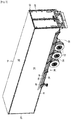
- a road transport vehicle body has been shown, referenced 10 as a whole, which is equipped with a chassis (not visible) extending longitudinally and supported by wheels 12.
- the bodywork 10 comprises two opposite vertical sidewalls 14 extending longitudinally (only one being visible on the figure), a ceiling or pavilion 16, a floor 18, and a front face 20 which are assembled together to delimit an interior loading space.
- the body 10 also includes a rear frame 22, also known as the quarter panel, having a function of stiffening the body.
- the rigid rear frame 22 is fixed to the rear ends of the sides 14, of the roof 16 and of the floor 18.
- the rear frame 22 can for example be made of steel, in particular stainless steel.
- the body 10 also includes a device 24 for closing an opening or rear access to the interior loading space.
- the closure device 24 is movable between a closed position of the rear access and at least one open position.
- the closure device 24 comprises a door with two leaves articulated in rotation on vertical uprights of the rear frame 22.
- the door can be with a single leaf.
- the closing device 24 may comprise a sliding closing curtain provided with a plurality of transverse panels hinged together.
- the bodywork 10 also comprises two opposite aerodynamic side fairings 26 (only one being visible in the figure) which extend longitudinally and which are each arranged below one of the sides 14 in the position illustrated in the figure 1 .
- the fairings 26 form right and left side fairings.
- the two fairings 26 are identical to each other.
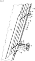
- Each fairing 26 comprises a plurality of panels 28, 30 and 32 arranged successively in the longitudinal direction. As will be described in more detail below, each panel 28 to 32 is movable in rotation about horizontal articulation axes between a lowered position of use as illustrated in the figure 1 and a raised position illustrated in figure 2 .
- each panel 28 to 32 In the lowered position of use, each panel 28 to 32 partly extends vertically downward the adjacent flank 14. In this position, each panel 28 to 32 is located vertically below said flank. In the raised position, panels 28 to 32 allow access under the floor 18. In the raised position, the panels 28 to 32 here extend obliquely upwards.
- each fairing 26 comprises three panels.
- the panel 28 is arranged in an area of the body called “wheelbase” or “pallet carrier”
- the panel 30 is arranged in an area called “running gear”
- the panel 32 is arranged in an area of the body called “door” false ".
- the number and / or the arrangement of the panels of each fairing 26 can be modified.
- the fairing 26 can also be further equipped with a movable panel for rotation about a horizontal articulation axis, for example in an area of the bodywork called “crutches”.
- the panel 28 of the side fairing comprises a plurality of sections 34, 36, 38, 40 extending longitudinally, and uprights 41 on which these panels are mounted. As will be described in more detail below, the uprights 41 are articulated to the floor 18 of the bodywork.
- the longitudinal profiles 34 to 40 are integral with the uprights 41.
- Each profile 34 to 40 can for example be made of metallic material, in particular aluminum or also of plastic material, in particular by extrusion.
- the profiles of the panel 28 are four in number. Alternatively, it is possible to provide a different number of profiles, for example two, three or five or more.
- the sections 34 to 40 are arranged successively in the height direction of the panel 28. In other words, the sections 34 to 40 are arranged one above the other.
- the profile referenced 38 is the lower profile of the panel 28 and the profile referenced 40 is the upper profile of said panel.
- the profiles 34 to 40 of the panel are configured to be assembled together by interlocking in the vertical direction. For this purpose, a throat longitudinal is practiced on each profile inside which is forced to engage a longitudinal groove complementary to the adjacent profile.
- Profiles 34 to 40 delimit an outer face 43 ( figure 1 ) of the panel which is continuous in the height direction. In other words, there is no vertical space between the profiles 34 to 40 and therefore a continuity of the outer faces of these profiles.
- the outer face 43 is also continuous in the longitudinal direction.
- the profiles 34 to 40 delimit an inner face 44 of the panel which is opposite in the transverse direction to the outer face 43.
- the panel 28 partially extends vertically downward the sidewall 14.
- the outer face 43 of the panel forms an aerodynamic face along which, during rolling, flows a flow air backwards.
- the upper profile 40 of the panel 28 comes to bear against a finishing belt (not referenced) mounted at the lower end of the sidewall 14.
- a finishing belt (not referenced) mounted at the lower end of the sidewall 14.
- Profiles 34 to 38 are fixed to the uprights 41 of the panel. Each profile 34 to 38 is fixed by bolting. Alternatively, it might be possible to provide another type of attachment.
- the upper section 40 is fixed by fitting onto the immediately adjacent section 34.
- the upper profile 40 can also be fixed by interlocking and bonding to the profile 34.
- the inner face 44 of the panel is mounted against the uprights 41.
- the amounts 41 are identical to each other.
- the uprights are in the form of straight bars.
- the uprights 41 can for example be made of metallic material, in particular steel.
- the uprights 41 of the panel 28 are two in number. Alternatively, it is possible to provide a different number of uprights.
- Each upright 41 is equipped, at an upper end, with a pair of plates 42 which are fixed to said upright.
- the plates 42 are here fixed by screwing.
- the two plates 42 of each upright are identical to each other.
- the plates 42 are arranged transversely to the profiles 34 to 40.
- the major part of each plate 42 extends transversely on the side opposite to the profiles 34 to 40 from the associated upright 41.
- each plate 42 comprises a tab 42a which is located axially between the upper end of the associated upright 41 and the sidewall 14 in the lowered position of use of the panel 28.
- the body 10 also comprises, associated with each pair of plates 42, a support 46 fixed under the floor 18.
- Each support 46 is fixed by any suitable means, for example by screwing.
- Each support 46 remains recessed inwardly relative to the flank 14.
- each support 46 comprises a base 46a and two wings 46b, 46c opposite and spaced.
- the base 46a is fixed to the floor 18 and the wings 46b, 46c oriented transversely extend vertically downwards the opposite ends of the base.
- Each support 46 thus has, in cross section, a U shape facing downwards.
- Each support 46 also includes a tab 46d extending each wing 46b, 46c.
- the legs 42a of the pair of uprights are received between the legs 46d of the associated support.
- a horizontal articulation axis 48 extends through these legs 42a, 46d.
- the articulation axis 48 is oriented longitudinally.
- the plates 42 of each upright 41 are located in the lowered position of the panel 28 between the wings 46b, 46c of the associated support.
- Each upright 41 of the panel 28 is articulated on the support 46 around the associated hinge axis 48. More specifically, the plates 42 integral with each upright 41 are articulated on the associated support 46. The plates 42 form a member for mounting each upright 41 on the associated support 46.
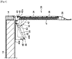
- the lateral fairing 26 also includes, for each upright 41 of the panel 28, an actuating cylinder 50 acting on the plates 42 associated with said upright.
- each cylinder 50 is mounted between the wings 46b, 46c of the associated support.
- Each actuator 50 comprises a body 52 articulated on the associated support 46, and a rod 54 articulated on the plates 42.
- the body 52 and the rod 54 of the actuating cylinder are respectively articulated in rotation about articulation axes 56, 58 horizontal.
- the articulation axes 56, 58 are oriented longitudinally and are distinct from the articulation axis 48 of the panel.
- the actuating cylinder 50 is of the pneumatic type. As a variant, it is possible to provide a hydraulic cylinder or even a mechanical cylinder comprising a spring inside a cage.
- the hinge axis 58 of the jack is offset inward and upward relative to the hinge axis 48 of the panel.
- the articulation axis 56 of the jack is offset inward and downward relative to the articulation axis 56 and relative to the articulation axis 48 of the panel.
- the jack 50 extends obliquely upwards and is oriented in the direction of the sidewall 14.
- each upright 41 of the panel 28 pivots about the associated hinge axis 48.
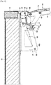
- neutral position is meant the position in which the hinge pins 56, 58 of the jack are aligned on the hinge pin 48 of the associated uprights as illustrated in the figure 7 .
- the lifting of the panel 28 can be carried out until the rod 54 of the jack is at the end of travel as illustrated in the figure 8 .
- the rod 54 of the jack in the raised position of the panel 28, there is no contact between it and the finishing belt mounted at the lower end of the sidewall 14.
- the rod 54 of the jack may not be at the end of its travel when the panel abuts against the belt.
- each jack 50 tends to keep the panel 28 in its lowered position.
- the panel 28 is equipped with a locking pin 60 cooperating with a rotary latch 62 mounted on the support 46 of one of the uprights of said panel as illustrated in the figure 9 .
- the pin 60 is mounted on one of the plates 42 of one of the uprights 41.
- the panel 28 is further equipped with a control lever 64 accessible from the outside to control the passage of the latch 62 from a locked position of the pin 60 to a locked position of said pin.
- the lever 64 is rotatably mounted on the hinge pin 48 of the panel.
- a connecting rod 66 is here provided between them.
- a first end of the connecting rod 66 is articulated in rotation on the lever 64 around a horizontal articulation axis (not referenced) and a second end of the connecting rod is articulated in rotation on the latch 62 around another axis d 'horizontal joint (not referenced).
- the rotary latch 62 comprises a housing 68 fixed on the wing 46b of the support, a cam 70 of locking inside which the pin 60 is housed, and a cam 72 for actuating the cam 70.
- the cams 70, 72 are pivotally mounted on the housing 68.
- the latch 62 further comprises two springs (not referenced) acting each on one of the cams 70, 72 for maintaining said latch in the unlocked state after actuation as will be described later.
- the operator Before being able to carry out this lifting of the panel 28, the operator must unlock the panel 28. To do this, the operator exerts a force on the panel 28 tending to obtain this lifting and simultaneously rotates the lever 64 clockwise, this pivoting having the effect of controlling the pivoting of the actuating cam 72 in a clockwise direction by means of the connecting rod 66. The pivoting of the cam 72 releases the cam 70 which, under the effect of the associated spring, pivots in turn clockwise in an unlocking position in which the locking pin 60 is no longer blocked by the cam 70 and can be disengaged from the latter.
- the panel 28 is also equipped with an adjustment pin 74 which is mounted on the plate 42 which does not include the locking pin 60.
- Each pin 60, 74 is fixed on the associated plate 42 and extends longitudinally projecting.
- the pins 60, 74 extend in opposite directions.
- the support 46 also includes an adjustment screw 76 which is engaged in a threaded hole arranged on a flange of said support and which comes to press vertically on the adjustment pin 74. This makes it possible to be able to adjust the angular inclination of the panel 28 by screwing the screw 76 so as to be able to align this panel in the longitudinal direction with the other panels 30, 32 of the side fairing.
- the plates 42 associated with each upright 41 abut against the support 46 fixed to the floor 18.
- the support 46 on which the latch 62 is mounted one of the plates 42 of the upright 41 associated bears against the latch 62 and the other plate 42 bears against the adjusting screw 76 in this lowered position of the panel 28.
- the support 46 without the latch 62 one of the plates 42 of the associated post 41 comes in press against the adjusting screw 76 in the lowered position of the panel 28.
- each panel 30, 32 on the body are similar to those which have just been described for the panel 28.
- the design and mounting of each panel 30, 32 on the body are similar to those which have just been described for the panel 28.
- the panel 28 only the length of the panels 30 and 32, the shape of the lower profile of these panels and the longitudinal position of the uprights associated with these panels differ.
- the invention has been illustrated by way of example on the basis of a body of a road transport vehicle of the semi-trailer type.
- the invention is also applicable to a body of a road transport vehicle of the carrier, truck, or trailer type.
Landscapes
- Engineering & Computer Science (AREA)
- Chemical & Material Sciences (AREA)
- Combustion & Propulsion (AREA)
- Transportation (AREA)
- Mechanical Engineering (AREA)
- Body Structure For Vehicles (AREA)
Priority Applications (1)
| Application Number | Priority Date | Filing Date | Title |
|---|---|---|---|
| PL19217324T PL3670308T3 (pl) | 2018-12-21 | 2019-12-18 | Nadwozie pojazdu drogowego do transportu towarów wyposażone w owiewki boczne |
Applications Claiming Priority (1)
| Application Number | Priority Date | Filing Date | Title |
|---|---|---|---|
| FR1873765A FR3090560B1 (fr) | 2018-12-21 | 2018-12-21 | Carrosserie de véhicule routier de transport de marchandises munie de carénages latéraux |
Publications (2)
| Publication Number | Publication Date |
|---|---|
| EP3670308A1 true EP3670308A1 (de) | 2020-06-24 |
| EP3670308B1 EP3670308B1 (de) | 2021-09-29 |
Family
ID=67956834
Family Applications (1)
| Application Number | Title | Priority Date | Filing Date |
|---|---|---|---|
| EP19217324.3A Active EP3670308B1 (de) | 2018-12-21 | 2019-12-18 | Karosserie eines strassenfahrzeugs für die beförderung von gütern, die mit seitenverkleidungen versehen ist |
Country Status (4)
| Country | Link |
|---|---|
| EP (1) | EP3670308B1 (de) |
| ES (1) | ES2902500T3 (de) |
| FR (1) | FR3090560B1 (de) |
| PL (1) | PL3670308T3 (de) |
Cited By (2)
| Publication number | Priority date | Publication date | Assignee | Title |
|---|---|---|---|---|
| US20220266925A1 (en) * | 2021-02-23 | 2022-08-25 | Barry Andersen | Apparatus and method for a skirt assembly |
| GB2607036A (en) * | 2021-05-25 | 2022-11-30 | Daimler Ag | Fairing assembly for a commercial vehicle |
Citations (5)
| Publication number | Priority date | Publication date | Assignee | Title |
|---|---|---|---|---|
| JPH0620174U (ja) * | 1992-05-07 | 1994-03-15 | 一彦 香味 | サイドスポイラ装置 |
| JPH06227334A (ja) * | 1993-02-01 | 1994-08-16 | Furomu One Kk | 貨物自動車の荷台スカート |
| WO2003093066A1 (en) * | 2002-02-28 | 2003-11-13 | Jan-Erik Norelius | Underrun protection for vehicles |
| US7374229B1 (en) * | 2007-02-09 | 2008-05-20 | International Truck Intellectual Property Company, Llc | Adjustable cab extender |
| DE102011106650A1 (de) * | 2011-07-05 | 2013-01-10 | Burg Silvergreen Gmbh | Seitlicher unterfahrschutz für lastkraftwagen |
-
2018
- 2018-12-21 FR FR1873765A patent/FR3090560B1/fr active Active
-
2019
- 2019-12-18 PL PL19217324T patent/PL3670308T3/pl unknown
- 2019-12-18 EP EP19217324.3A patent/EP3670308B1/de active Active
- 2019-12-18 ES ES19217324T patent/ES2902500T3/es active Active
Patent Citations (5)
| Publication number | Priority date | Publication date | Assignee | Title |
|---|---|---|---|---|
| JPH0620174U (ja) * | 1992-05-07 | 1994-03-15 | 一彦 香味 | サイドスポイラ装置 |
| JPH06227334A (ja) * | 1993-02-01 | 1994-08-16 | Furomu One Kk | 貨物自動車の荷台スカート |
| WO2003093066A1 (en) * | 2002-02-28 | 2003-11-13 | Jan-Erik Norelius | Underrun protection for vehicles |
| US7374229B1 (en) * | 2007-02-09 | 2008-05-20 | International Truck Intellectual Property Company, Llc | Adjustable cab extender |
| DE102011106650A1 (de) * | 2011-07-05 | 2013-01-10 | Burg Silvergreen Gmbh | Seitlicher unterfahrschutz für lastkraftwagen |
Cited By (3)
| Publication number | Priority date | Publication date | Assignee | Title |
|---|---|---|---|---|
| US20220266925A1 (en) * | 2021-02-23 | 2022-08-25 | Barry Andersen | Apparatus and method for a skirt assembly |
| US11904954B2 (en) * | 2021-02-23 | 2024-02-20 | Barry Andersen | Apparatus and method for a skirt assembly |
| GB2607036A (en) * | 2021-05-25 | 2022-11-30 | Daimler Ag | Fairing assembly for a commercial vehicle |
Also Published As
| Publication number | Publication date |
|---|---|
| PL3670308T4 (pl) | 2022-06-13 |
| FR3090560A1 (fr) | 2020-06-26 |
| PL3670308T3 (pl) | 2022-06-13 |
| ES2902500T3 (es) | 2022-03-28 |
| EP3670308B1 (de) | 2021-09-29 |
| FR3090560B1 (fr) | 2022-05-27 |
Similar Documents
| Publication | Publication Date | Title |
|---|---|---|
| EP1215107B1 (de) | Kraftfahrzeug mit verlängbaren Ladepritschen | |
| EP2692561B1 (de) | Vorrichtung zum Verschliessen des Laderaumes eines Transportfahrzeuges | |
| EP3670308B1 (de) | Karosserie eines strassenfahrzeugs für die beförderung von gütern, die mit seitenverkleidungen versehen ist | |
| FR2867443A1 (fr) | Remorque routiere polyvalente et evolutive | |
| EP3650322B1 (de) | Karosserie eines strassenfahrzeugs für den warentransport, die rückspoiler umfasst | |
| WO2005080108A1 (fr) | Dispositif de fermeture pour vehicule pourvu d’un hayon arriere et d’un toit ouvrant | |
| EP2505429B1 (de) | Verfahren zur Regulierung des Achsabstands einer rollenden Einheit, die mindestens zwei Fördervorrichtungen für Container umfasst | |
| EP4556664A1 (de) | Zugangsvorrichtung für ein kraftfahrzeug mit antagonistischen türen | |
| FR2527256A2 (fr) | Dispositif d'ouverture a surface decouvrable, notamment toit ouvrant pour vehicule automobile | |
| WO2012150222A1 (fr) | Dispositif de manutention | |
| EP2228262B1 (de) | Unterstützungsvorrichtung für das Be-oder Entladen eines Fahrzeugkofferraums und Fahrzeug hierfür | |
| EP3760482B1 (de) | Optimierte ladefläche für autotransporter, und anhänger oder sattelauflieger, der mit einer solchen ladefläche ausgestattet ist | |
| EP4328120B1 (de) | Strassenfahrzeugkarosserie zum transport von gütern mit heckspoilern | |
| EP4556311B1 (de) | Partitionierungsvorrichtung mit einem befestigungsstab für eine kühlkarosserie | |
| EP2756989B1 (de) | Halte- und/oder Verstauungssystem von Waren, insbesondere für Straßentransportfahrzeuge | |
| FR2783495A1 (fr) | Porte d'aeronef pressurise | |
| FR2821341A1 (fr) | Toit ouvrant pour conteneur du type benne, et conteneur ainsi equipe | |
| WO2005080107A1 (fr) | Vehicule a toit decouvrable et hayon arriere | |
| EP0741052A1 (de) | Gestell zur Abdeckung eines Nutzfahrzeuges mit einer bewegbaren Runge | |
| EP2990263B1 (de) | Strassentransportfahrzeug mit einer haltestruktur zum beladen mit automatischem ein- und ausklinksystem | |
| FR3145548A1 (fr) | Ensemble de porte d’accès pour un aéronef | |
| FR3126931A1 (fr) | Carrosserie de véhicule routier de transport de marchandises munie d’un rideau de fermeture coulissant à actionnement manuel | |
| FR3074132A1 (fr) | Dispositif de ridelle d'un conteneur d'un vehicule de transport de charge | |
| FR2922169A1 (fr) | Systeme de galerie escamotable pour vehicule automobile, commande par un levier, et vehicule correspondant | |
| FR3082470A1 (fr) | Systeme d'arrimage d'un chariot elevateur a l'interieur d'une carrosserie de vehicule routier de transport de marchandises |
Legal Events
| Date | Code | Title | Description |
|---|---|---|---|
| PUAI | Public reference made under article 153(3) epc to a published international application that has entered the european phase |
Free format text: ORIGINAL CODE: 0009012 |
|
| STAA | Information on the status of an ep patent application or granted ep patent |
Free format text: STATUS: THE APPLICATION HAS BEEN PUBLISHED |
|
| AK | Designated contracting states |
Kind code of ref document: A1 Designated state(s): AL AT BE BG CH CY CZ DE DK EE ES FI FR GB GR HR HU IE IS IT LI LT LU LV MC MK MT NL NO PL PT RO RS SE SI SK SM TR |
|
| AX | Request for extension of the european patent |
Extension state: BA ME |
|
| STAA | Information on the status of an ep patent application or granted ep patent |
Free format text: STATUS: REQUEST FOR EXAMINATION WAS MADE |
|
| 17P | Request for examination filed |
Effective date: 20200904 |
|
| GRAP | Despatch of communication of intention to grant a patent |
Free format text: ORIGINAL CODE: EPIDOSNIGR1 |
|
| STAA | Information on the status of an ep patent application or granted ep patent |
Free format text: STATUS: GRANT OF PATENT IS INTENDED |
|
| RIC1 | Information provided on ipc code assigned before grant |
Ipc: B62D 35/00 20060101AFI20210531BHEP Ipc: B62D 25/18 20060101ALI20210531BHEP |
|
| INTG | Intention to grant announced |
Effective date: 20210615 |
|
| GRAS | Grant fee paid |
Free format text: ORIGINAL CODE: EPIDOSNIGR3 |
|
| GRAA | (expected) grant |
Free format text: ORIGINAL CODE: 0009210 |
|
| STAA | Information on the status of an ep patent application or granted ep patent |
Free format text: STATUS: THE PATENT HAS BEEN GRANTED |
|
| AK | Designated contracting states |
Kind code of ref document: B1 Designated state(s): AL AT BE BG CH CY CZ DE DK EE ES FI FR GB GR HR HU IE IS IT LI LT LU LV MC MK MT NL NO PL PT RO RS SE SI SK SM TR |
|
| REG | Reference to a national code |
Ref country code: GB Ref legal event code: FG4D Free format text: NOT ENGLISH |
|
| REG | Reference to a national code |
Ref country code: CH Ref legal event code: EP Ref country code: AT Ref legal event code: REF Ref document number: 1433968 Country of ref document: AT Kind code of ref document: T Effective date: 20211015 |
|
| REG | Reference to a national code |
Ref country code: DE Ref legal event code: R096 Ref document number: 602019008018 Country of ref document: DE |
|
| REG | Reference to a national code |
Ref country code: IE Ref legal event code: FG4D Free format text: LANGUAGE OF EP DOCUMENT: FRENCH |
|
| REG | Reference to a national code |
Ref country code: LT Ref legal event code: MG9D |
|
| PG25 | Lapsed in a contracting state [announced via postgrant information from national office to epo] |
Ref country code: NO Free format text: LAPSE BECAUSE OF FAILURE TO SUBMIT A TRANSLATION OF THE DESCRIPTION OR TO PAY THE FEE WITHIN THE PRESCRIBED TIME-LIMIT Effective date: 20211229 Ref country code: FI Free format text: LAPSE BECAUSE OF FAILURE TO SUBMIT A TRANSLATION OF THE DESCRIPTION OR TO PAY THE FEE WITHIN THE PRESCRIBED TIME-LIMIT Effective date: 20210929 Ref country code: HR Free format text: LAPSE BECAUSE OF FAILURE TO SUBMIT A TRANSLATION OF THE DESCRIPTION OR TO PAY THE FEE WITHIN THE PRESCRIBED TIME-LIMIT Effective date: 20210929 Ref country code: LT Free format text: LAPSE BECAUSE OF FAILURE TO SUBMIT A TRANSLATION OF THE DESCRIPTION OR TO PAY THE FEE WITHIN THE PRESCRIBED TIME-LIMIT Effective date: 20210929 Ref country code: BG Free format text: LAPSE BECAUSE OF FAILURE TO SUBMIT A TRANSLATION OF THE DESCRIPTION OR TO PAY THE FEE WITHIN THE PRESCRIBED TIME-LIMIT Effective date: 20211229 Ref country code: RS Free format text: LAPSE BECAUSE OF FAILURE TO SUBMIT A TRANSLATION OF THE DESCRIPTION OR TO PAY THE FEE WITHIN THE PRESCRIBED TIME-LIMIT Effective date: 20210929 Ref country code: SE Free format text: LAPSE BECAUSE OF FAILURE TO SUBMIT A TRANSLATION OF THE DESCRIPTION OR TO PAY THE FEE WITHIN THE PRESCRIBED TIME-LIMIT Effective date: 20210929 |
|
| REG | Reference to a national code |
Ref country code: NL Ref legal event code: MP Effective date: 20210929 |
|
| REG | Reference to a national code |
Ref country code: AT Ref legal event code: MK05 Ref document number: 1433968 Country of ref document: AT Kind code of ref document: T Effective date: 20210929 |
|
| PG25 | Lapsed in a contracting state [announced via postgrant information from national office to epo] |
Ref country code: LV Free format text: LAPSE BECAUSE OF FAILURE TO SUBMIT A TRANSLATION OF THE DESCRIPTION OR TO PAY THE FEE WITHIN THE PRESCRIBED TIME-LIMIT Effective date: 20210929 Ref country code: GR Free format text: LAPSE BECAUSE OF FAILURE TO SUBMIT A TRANSLATION OF THE DESCRIPTION OR TO PAY THE FEE WITHIN THE PRESCRIBED TIME-LIMIT Effective date: 20211230 |
|
| REG | Reference to a national code |
Ref country code: ES Ref legal event code: FG2A Ref document number: 2902500 Country of ref document: ES Kind code of ref document: T3 Effective date: 20220328 |
|
| PG25 | Lapsed in a contracting state [announced via postgrant information from national office to epo] |
Ref country code: AT Free format text: LAPSE BECAUSE OF FAILURE TO SUBMIT A TRANSLATION OF THE DESCRIPTION OR TO PAY THE FEE WITHIN THE PRESCRIBED TIME-LIMIT Effective date: 20210929 |
|
| PG25 | Lapsed in a contracting state [announced via postgrant information from national office to epo] |
Ref country code: IS Free format text: LAPSE BECAUSE OF FAILURE TO SUBMIT A TRANSLATION OF THE DESCRIPTION OR TO PAY THE FEE WITHIN THE PRESCRIBED TIME-LIMIT Effective date: 20220129 Ref country code: SK Free format text: LAPSE BECAUSE OF FAILURE TO SUBMIT A TRANSLATION OF THE DESCRIPTION OR TO PAY THE FEE WITHIN THE PRESCRIBED TIME-LIMIT Effective date: 20210929 Ref country code: RO Free format text: LAPSE BECAUSE OF FAILURE TO SUBMIT A TRANSLATION OF THE DESCRIPTION OR TO PAY THE FEE WITHIN THE PRESCRIBED TIME-LIMIT Effective date: 20210929 Ref country code: PT Free format text: LAPSE BECAUSE OF FAILURE TO SUBMIT A TRANSLATION OF THE DESCRIPTION OR TO PAY THE FEE WITHIN THE PRESCRIBED TIME-LIMIT Effective date: 20220131 Ref country code: NL Free format text: LAPSE BECAUSE OF FAILURE TO SUBMIT A TRANSLATION OF THE DESCRIPTION OR TO PAY THE FEE WITHIN THE PRESCRIBED TIME-LIMIT Effective date: 20210929 Ref country code: EE Free format text: LAPSE BECAUSE OF FAILURE TO SUBMIT A TRANSLATION OF THE DESCRIPTION OR TO PAY THE FEE WITHIN THE PRESCRIBED TIME-LIMIT Effective date: 20210929 Ref country code: CZ Free format text: LAPSE BECAUSE OF FAILURE TO SUBMIT A TRANSLATION OF THE DESCRIPTION OR TO PAY THE FEE WITHIN THE PRESCRIBED TIME-LIMIT Effective date: 20210929 Ref country code: AL Free format text: LAPSE BECAUSE OF FAILURE TO SUBMIT A TRANSLATION OF THE DESCRIPTION OR TO PAY THE FEE WITHIN THE PRESCRIBED TIME-LIMIT Effective date: 20210929 |
|
| REG | Reference to a national code |
Ref country code: DE Ref legal event code: R097 Ref document number: 602019008018 Country of ref document: DE |
|
| PG25 | Lapsed in a contracting state [announced via postgrant information from national office to epo] |
Ref country code: MC Free format text: LAPSE BECAUSE OF FAILURE TO SUBMIT A TRANSLATION OF THE DESCRIPTION OR TO PAY THE FEE WITHIN THE PRESCRIBED TIME-LIMIT Effective date: 20210929 Ref country code: DK Free format text: LAPSE BECAUSE OF FAILURE TO SUBMIT A TRANSLATION OF THE DESCRIPTION OR TO PAY THE FEE WITHIN THE PRESCRIBED TIME-LIMIT Effective date: 20210929 |
|
| PLBE | No opposition filed within time limit |
Free format text: ORIGINAL CODE: 0009261 |
|
| STAA | Information on the status of an ep patent application or granted ep patent |
Free format text: STATUS: NO OPPOSITION FILED WITHIN TIME LIMIT |
|
| 26N | No opposition filed |
Effective date: 20220630 |
|
| REG | Reference to a national code |
Ref country code: BE Ref legal event code: MM Effective date: 20211231 |
|
| PG25 | Lapsed in a contracting state [announced via postgrant information from national office to epo] |
Ref country code: LU Free format text: LAPSE BECAUSE OF NON-PAYMENT OF DUE FEES Effective date: 20211218 Ref country code: IE Free format text: LAPSE BECAUSE OF NON-PAYMENT OF DUE FEES Effective date: 20211218 |
|
| PG25 | Lapsed in a contracting state [announced via postgrant information from national office to epo] |
Ref country code: SI Free format text: LAPSE BECAUSE OF FAILURE TO SUBMIT A TRANSLATION OF THE DESCRIPTION OR TO PAY THE FEE WITHIN THE PRESCRIBED TIME-LIMIT Effective date: 20210929 Ref country code: BE Free format text: LAPSE BECAUSE OF NON-PAYMENT OF DUE FEES Effective date: 20211231 |
|
| PG25 | Lapsed in a contracting state [announced via postgrant information from national office to epo] |
Ref country code: CY Free format text: LAPSE BECAUSE OF FAILURE TO SUBMIT A TRANSLATION OF THE DESCRIPTION OR TO PAY THE FEE WITHIN THE PRESCRIBED TIME-LIMIT Effective date: 20210929 |
|
| PG25 | Lapsed in a contracting state [announced via postgrant information from national office to epo] |
Ref country code: SM Free format text: LAPSE BECAUSE OF FAILURE TO SUBMIT A TRANSLATION OF THE DESCRIPTION OR TO PAY THE FEE WITHIN THE PRESCRIBED TIME-LIMIT Effective date: 20210929 Ref country code: HU Free format text: LAPSE BECAUSE OF FAILURE TO SUBMIT A TRANSLATION OF THE DESCRIPTION OR TO PAY THE FEE WITHIN THE PRESCRIBED TIME-LIMIT; INVALID AB INITIO Effective date: 20191218 |
|
| REG | Reference to a national code |
Ref country code: CH Ref legal event code: PL |
|
| PG25 | Lapsed in a contracting state [announced via postgrant information from national office to epo] |
Ref country code: LI Free format text: LAPSE BECAUSE OF NON-PAYMENT OF DUE FEES Effective date: 20221231 Ref country code: CH Free format text: LAPSE BECAUSE OF NON-PAYMENT OF DUE FEES Effective date: 20221231 |
|
| PG25 | Lapsed in a contracting state [announced via postgrant information from national office to epo] |
Ref country code: MK Free format text: LAPSE BECAUSE OF FAILURE TO SUBMIT A TRANSLATION OF THE DESCRIPTION OR TO PAY THE FEE WITHIN THE PRESCRIBED TIME-LIMIT Effective date: 20210929 |
|
| PG25 | Lapsed in a contracting state [announced via postgrant information from national office to epo] |
Ref country code: TR Free format text: LAPSE BECAUSE OF FAILURE TO SUBMIT A TRANSLATION OF THE DESCRIPTION OR TO PAY THE FEE WITHIN THE PRESCRIBED TIME-LIMIT Effective date: 20210929 |
|
| PG25 | Lapsed in a contracting state [announced via postgrant information from national office to epo] |
Ref country code: MT Free format text: LAPSE BECAUSE OF FAILURE TO SUBMIT A TRANSLATION OF THE DESCRIPTION OR TO PAY THE FEE WITHIN THE PRESCRIBED TIME-LIMIT Effective date: 20210929 |
|
| P01 | Opt-out of the competence of the unified patent court (upc) registered |
Free format text: CASE NUMBER: UPC_APP_427118/2023 Effective date: 20230525 |
|
| PGFP | Annual fee paid to national office [announced via postgrant information from national office to epo] |
Ref country code: GB Payment date: 20251229 Year of fee payment: 7 |
|
| PGFP | Annual fee paid to national office [announced via postgrant information from national office to epo] |
Ref country code: IT Payment date: 20251210 Year of fee payment: 7 |
|
| PGFP | Annual fee paid to national office [announced via postgrant information from national office to epo] |
Ref country code: FR Payment date: 20251230 Year of fee payment: 7 |
|
| PGFP | Annual fee paid to national office [announced via postgrant information from national office to epo] |
Ref country code: PL Payment date: 20251121 Year of fee payment: 7 |
|
| PGFP | Annual fee paid to national office [announced via postgrant information from national office to epo] |
Ref country code: ES Payment date: 20260112 Year of fee payment: 7 |
|
| PGFP | Annual fee paid to national office [announced via postgrant information from national office to epo] |
Ref country code: DE Payment date: 20251231 Year of fee payment: 7 |