EP3670417A1 - Chargement d'alimentation sans fil de voiture à point d'appel - Google Patents
Chargement d'alimentation sans fil de voiture à point d'appel Download PDFInfo
- Publication number
- EP3670417A1 EP3670417A1 EP19215396.3A EP19215396A EP3670417A1 EP 3670417 A1 EP3670417 A1 EP 3670417A1 EP 19215396 A EP19215396 A EP 19215396A EP 3670417 A1 EP3670417 A1 EP 3670417A1
- Authority
- EP
- European Patent Office
- Prior art keywords
- electrical power
- wireless
- wireless electrical
- elevator
- energy storage
- Prior art date
- Legal status (The legal status is an assumption and is not a legal conclusion. Google has not performed a legal analysis and makes no representation as to the accuracy of the status listed.)
- Withdrawn
Links
Images

Classifications
-
- H—ELECTRICITY
- H02—GENERATION; CONVERSION OR DISTRIBUTION OF ELECTRIC POWER
- H02J—ELECTRIC POWER NETWORKS; CIRCUIT ARRANGEMENTS OR SYSTEMS FOR SUPPLYING OR DISTRIBUTING ELECTRIC POWER; SYSTEMS FOR STORING ELECTRIC ENERGY
- H02J50/00—Circuit arrangements or systems for wireless supply or distribution of electric power
- H02J50/10—Circuit arrangements or systems for wireless supply or distribution of electric power using inductive coupling
-
- H—ELECTRICITY
- H02—GENERATION; CONVERSION OR DISTRIBUTION OF ELECTRIC POWER
- H02J—ELECTRIC POWER NETWORKS; CIRCUIT ARRANGEMENTS OR SYSTEMS FOR SUPPLYING OR DISTRIBUTING ELECTRIC POWER; SYSTEMS FOR STORING ELECTRIC ENERGY
- H02J50/00—Circuit arrangements or systems for wireless supply or distribution of electric power
-
- B—PERFORMING OPERATIONS; TRANSPORTING
- B66—HOISTING; LIFTING; HAULING
- B66B—ELEVATORS; ESCALATORS OR MOVING WALKWAYS
- B66B11/00—Main component parts of lifts in, or associated with, buildings or other structures
- B66B11/02—Cages, i.e. cars
- B66B11/0226—Constructional features, e.g. walls assembly, decorative panels, comfort equipment, thermal or sound insulation
-
- B—PERFORMING OPERATIONS; TRANSPORTING
- B66—HOISTING; LIFTING; HAULING
- B66B—ELEVATORS; ESCALATORS OR MOVING WALKWAYS
- B66B7/00—Other common features of elevators
-
- H—ELECTRICITY
- H02—GENERATION; CONVERSION OR DISTRIBUTION OF ELECTRIC POWER
- H02J—ELECTRIC POWER NETWORKS; CIRCUIT ARRANGEMENTS OR SYSTEMS FOR SUPPLYING OR DISTRIBUTING ELECTRIC POWER; SYSTEMS FOR STORING ELECTRIC ENERGY
- H02J7/00—Circuit arrangements for charging or discharging batteries or for supplying loads from batteries
- H02J7/02—Circuit arrangements for charging or discharging batteries or for supplying loads from batteries for charging batteries from AC mains by converters
Definitions
- the embodiments herein relate to the field of conveyance systems, and specifically to a method and apparatus for powering components of a conveyance system.
- Conveyance systems such as, for example, elevator systems, escalator systems, and moving walkways require electric power for operation.
- Travelling cables typically connect an elevator car of the elevator system to a stationary power source to provide power to the elevator car. Travelling cables add expense, weight, and complexity to elevator car operation and installation, thus improved methods of powering elevator cars are desired.
- a wireless power transfer system for wirelessly powering a secondary wireless component using a conveyance apparatus of a conveyance system.
- the wireless power transfer system including: a secondary wireless component located along a support or a side of the conveyance system in a first location, the secondary wireless component including a wireless electrical power receiver; and a wireless electrical power transceiver located along a surface of the conveyance apparatus opposite the support or the side, the wireless electrical power transceiver and the wireless electrical power receiver being in a facing spaced relationship defining a gap therebetween when the wireless electrical power transceiver is located proximate the first location, wherein the wireless electrical power transceiver is configured to wirelessly transfer electrical power to the wireless electrical power receiver when the wireless electrical power transceiver is located proximate the first location.
- further embodiments may include that the conveyance system is an elevator system and the conveyance apparatus is an elevator car.
- further embodiments may include that the side is a wall of an elevator hoistway of the elevator system.
- further embodiments may include that the secondary wireless component further includes an energy storage device electrically connected to the wireless electrical power receiver.
- the secondary wireless component further includes at least one of an input device electrically powered by the energy storage device and an output device electrically powered by the energy storage device.
- further embodiments may include that the secondary wireless component is an elevator call placement device.
- further embodiments may include that the secondary wireless component is an elevator indicator.
- further embodiments may include: a wireless electrical power transmitter located along a support or a side of the conveyance system in a second location, wherein the wireless electrical power transmitter is configured to wirelessly transfer electrical power to the wireless electrical power transceiver when the wireless electrical power transceiver is located proximate the second location.
- the secondary wireless component further includes: an energy storage device electrically connected to the wireless electrical power receiver; and at least one of an input device electrically powered by the energy storage device and an output device electrically powered by the energy storage device, wherein the secondary wireless component is an elevator call placement device.
- further embodiments may include: a wireless electrical power transmitter located along a support or a wall of the elevator system in a second location, wherein the wireless electrical power transmitter is configured to wirelessly transfer electrical power to the wireless electrical power transceiver when the wireless electrical power transceiver is located proximate the second location.
- a conveyance system including: a conveyance apparatus; and a wireless power transfer system for wirelessly powering a secondary wireless component using the conveyance apparatus of the conveyance system, the wireless power transfer system including: a secondary wireless component located along a support or a side of the conveyance system in a first location, the secondary wireless component including a wireless electrical power receiver; and a wireless electrical power transceiver located along a surface of the conveyance apparatus opposite the support or the side, the wireless electrical power transceiver and the wireless electrical power receiver being in a facing spaced relationship defining a gap therebetween when the wireless electrical power transceiver is located proximate the first location, wherein the wireless electrical power transceiver is configured to wirelessly transfer electrical power to the wireless electrical power receiver when the wireless electrical power transceiver is located proximate the first location.
- further embodiments may include that the conveyance system is an elevator system and the conveyance apparatus is an elevator car.
- further embodiments may include that the side is a wall of an elevator hoistway of the elevator system.
- further embodiments may include that the secondary wireless component further includes an energy storage device electrically connected to the wireless electrical power receiver.
- the secondary wireless component further includes at least one of an input device electrically powered by the energy storage device and an output device electrically powered by the energy storage device.
- further embodiments may include that the secondary wireless component is an elevator call placement device.
- further embodiments may include that the secondary wireless component is an elevator indicator.
- the wireless power transfer system further includes: a wireless electrical power transmitter located along a support or a side of the conveyance system in a second location, wherein the wireless electrical power transmitter is configured to wirelessly transfer electrical power to the wireless electrical power transceiver when the wireless electrical power transceiver is located proximate the second location.
- the secondary wireless component further includes: an energy storage device electrically connected to the wireless electrical power receiver; and at least one of an input device electrically powered by the energy storage device and an output device electrically powered by the energy storage device, wherein the secondary wireless component is an elevator call placement device.
- further embodiments may include: a wireless electrical power transmitter located along a support or a side of the elevator system in a second location, wherein the wireless electrical power transmitter is configured to wirelessly transfer electrical power to the wireless electrical power transceiver when the wireless electrical power transceiver is located proximate the second location.
- FIG. 1 is a perspective view of an elevator system 101 including an elevator car 103, a counterweight 105, a tension member 107, a guide rail 109, a machine 111, a position reference system 113, and a controller 115.
- the elevator car 103 and counterweight 105 are connected to each other by the tension member 107.
- the tension member 107 may include or be configured as, for example, ropes, steel cables, and/or coated-steel belts.
- the counterweight 105 is configured to balance a load of the elevator car 103 and is configured to facilitate movement of the elevator car 103 concurrently and in an opposite direction with respect to the counterweight 105 within an elevator shaft 117 and along the guide rail 109.
- the tension member 107 engages the machine 111, which is part of an overhead structure of the elevator system 101.
- the machine 111 is configured to control movement between the elevator car 103 and the counterweight 105.
- the position reference system 113 may be mounted on a fixed part at the top of the elevator shaft 117, such as on a support or guide rail, and may be configured to provide position signals related to a position of the elevator car 103 within the elevator shaft 117. In other embodiments, the position reference system 113 may be directly mounted to a moving component of the machine 111, or may be located in other positions and/or configurations as known in the art.
- the position reference system 113 can be any device or mechanism for monitoring a position of an elevator car and/or counter weight, as known in the art.
- the position reference system 113 can be an encoder, sensor, or other system and can include velocity sensing, absolute position sensing, etc., as will be appreciated by those of skill in the art.
- the controller 115 is located, as shown, in a controller room 121 of the elevator shaft 117 and is configured to control the operation of the elevator system 101, and particularly the elevator car 103.
- the controller 115 may provide drive signals to the machine 111 to control the acceleration, deceleration, leveling, stopping, etc. of the elevator car 103.
- the controller 115 may also be configured to receive position signals from the position reference system 113 or any other desired position reference device.
- the elevator car 103 may stop at one or more landings 125 as controlled by the controller 115.
- the controller 115 can be located and/or configured in other locations or positions within the elevator system 101. In one embodiment, the controller may be located remotely or in the cloud.
- the machine 111 may include a motor or similar driving mechanism.
- the machine 111 is configured to include an electrically driven motor.
- the power supply for the motor may be any power source, including a power grid, which, in combination with other components, is supplied to the motor.
- the machine 111 may include a traction sheave that imparts force to tension member 107 to move the elevator car 103 within elevator shaft 117.
- FIG. 1 is merely a non-limiting example presented for illustrative and explanatory purposes.
- the system comprises a conveyance system that moves passengers between floors and/or along a single floor.
- conveyance systems may include escalators, people movers, etc.
- embodiments described herein are not limited to elevator systems, such as that shown in Figure 1 .
- embodiments disclosed herein may be applicable conveyance systems such as an elevator system 101 and a conveyance apparatus of the conveyance system such as an elevator car 103 of the elevator system 101.
- embodiments disclosed herein may be applicable conveyance systems such as an escalator system and a conveyance apparatus of the conveyance system such as a moving stair of the escalator system.
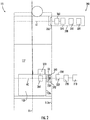
- the wireless power transfer system 200 may include a power source 210, an AC/DC power converter 220, a power management system 230, a wireless electrical power transmitter 240, a wireless electrical power transceiver 250, an energy storage device management system 260, an energy storage device 270, and a secondary wireless component 300.
- An energy storage device 270 may not be required if energy harvesting is used.
- the power source 210 may be a stationary power source, such as, for example electrical grid power, wind power, solar power, generator power, etc.
- the power source 210 may provide electrical power using alternating current (AC).
- the AC electrical power provided by the power source 210 may be three phase AC for higher power greater than about 3kW.
- the AC/DC power converter 220 is configured to receive the AC electric power from the power source 210 and convert the AC electrical power into DC electrical power.
- the AC/DC power converter 220 is electrically connected to the power source 210.
- the electrical connection between the AC/DC power converter 220 and the power source 210 may be hardwired.
- the power management system 230 is electrically connected to the AC/DC power converter 220.
- the electrical connection between the power management system 230 and the AC/DC power converter 220 may be hardwired.
- the power management system 230 operates as a power controller to supply the power needs of the elevator car 103 proximate a second location A2 and a first location A1.
- the second location A2 and the first location A1 may be a planes through the elevator shaft 117 about perpendicular to an axis X1 that runs parallel to the elevator shaft 117.
- the power management system 230 controls switching, directing, or redirecting power to the elevator car 103 through one or more wireless power transmitters 240 as needed to satisfy the power requirements of the elevator car 103.
- the bus control switching device 232 may include, but not be limited to, electromechanical and solid state semiconductor switching devices including relays, contactors, solid state contactors as well as semiconductor switching devices such as transistors, FETs, MOSFETS, IGBT's, thyristors, SCR's, and the like.
- the voltages and frequencies of the power supplied by the power source 210 may be adjusted by the bus control switching device 232.
- the wireless power transmitters 240 may later adjust the frequency of the electrical power to satisfy the needs of the elevator car 103.
- the wireless power transfer system 200 may include a wireless electrical power transmitters 240, as shown in FIG. 2 .
- the electrical power transmitters 240 are electrically connected to the power management system 230.
- the electrical connection between the electrical power transmitter 240 and the power management system 230 may be hardwired.
- the wireless electrical power transmitter 240 may be located at a second location A2 along a wall 117a of the elevator shaft 117.
- the wireless electrical power transmitter 240 may be attached to the wall 117a or embedded in the wall 117a, or in any other desired arrangement.
- the wireless electrical power transmitter 240 may include a selected number of electrical coils configured to generate a magnetic field 242 when electrical power is run through the electrical coils.
- the electrical coils of the wireless electrical power transmitter 240 are not shown in FIG. 2 for simplification of the illustration.
- the wireless power transfer system 200 may include a wireless electrical power transceiver 250, as shown in FIG. 2 .
- the wireless electrical power transceiver 250 may be located at a location along a surface 103a of the elevator car 103.
- the wireless electrical power transceiver 250 may be attached to the surface 103a of the elevator car 103 or embedded in the surface 103a of the elevator car 103.
- the surface 103a of the elevator car 103 is located opposite the wall 117a of the elevator hoistway 117 where the wireless electrical power transmitter 240 is located.
- the wireless electrical power transceiver 250 and the wireless electrical power transmitter 240 at the second location A2 are in a facing spaced relationship and a gap G1 is formed therebetween.
- the gap G1 is formed between the wireless electrical power transceiver 250 and the wireless electrical power transmitter 240 at the second location A2, as shown in FIG. 2 .
- the wireless electrical power transceiver 250 may include a selected number of electrical coils configured to generate an electric power in response to the magnetic field 242 when the wireless electrical power transceiver 250 is within the transmission range of the magnetic field 242 generated by the wireless electrical power transmitter 240.
- the electrical coils of the wireless electrical power transceiver 250 are not shown in FIG. 2 for simplification of the illustration.
- the electrical power transceiver 250 are electrically connected to the energy storage device management system 260.
- the electrical connection between the electrical power receiver 250 and the energy storage device management system 260 may be hardwired.
- the energy storage device management system 260 is configured to condition the electrical power received from the electrical power transceiver 250 and transfer the electrical power to the energy storage device 270 as needed.
- the energy storage device management system 260 monitors operation data of the energy storage device 270 including but not limited to the state of charge of the energy storage device 270, a state of health of the energy storage device 270, and a temperature of the energy storage device 270.
- Examples of the energy storage device 270 may include a battery system (e.g., a battery or bank of batteries), fuel cells, flow battery, and others devices capable of storing and outputting electric energy that may be DC.
- the energy storage device 270 may store potential energy rather than electrical energy and that potential energy may be utilized to create electrical energy for the elevator car 103a, 130b.
- the energy storage device 270 may include a battery system, which may employ multiple batteries organized into battery banks.
- the energy storage device 270 is electrically connected to the elevator car 103. The electrical connection between the energy storage device 270 and the elevator car 103 may be hardwired.
- the energy storage device 270 may power lighting inside the elevator car 103, fans, an emergency phone, climate controls, communication system, and/or the operating panel of the elevator car 103.
- the operating panel of the elevator car 103 may consists of floor buttons, a door open button, a door close button, other similar buttons, or may be a touchscreen.
- the energy storage device 270 of the elevator car 103 may discharge to power the elevator car 103 and/or a secondary wireless component 300 located along the elevator shaft 117, such as, for example an elevator call placement device, an elevator landing light, indicator, or an elevator landing display device.
- the secondary wireless component 300 may be wireless and may be solely powered by the discharge of the energy storage device 270, which charges an energy storage device 370 of the secondary wireless component 300.
- the secondary wireless component 300 comprises a wireless electrical power receiver 350, an energy storage device management system 360, and the energy storage device 370.
- the secondary wireless component 300 may also include an input device 310, and an output device 320.
- the input device 310 may be a key pad, button, or touch screen for receiving a user input (e.g., a user input to place an elevator call).
- the display device 320 may be a computer monitor, light, or touch screen.
- the wireless electrical power transceiver 250 may be located at a first location A1 along a wall 117a of the elevator shaft 117.
- the wireless electrical power receiver 350 may be attached to the wall 117a of the elevator shaft or embedded in the wall 117a of the elevator shaft 117. Alternatively, the wireless electrical power receiver 350 may be attached to a support between two elevator shafts 117.
- the wireless electrical power transceiver 250 and the wireless electrical power receiver 350 are in a facing spaced relationship.
- the gap G1 will also be present between the wireless electrical power transceiver 250 and the wireless electrical power receiver 350 proximate the first location A1.
- the wireless electrical power receiver 350 may include a selected number of electrical coils configured to generate an electric power in response to a magnetic field generated the wireless electrical power transceiver 250 when the wireless electrical power receiver 350 is within the transmission range of the magnetic field generated by the wireless electrical power transceiver 350.
- the electrical coils of the wireless electrical power receiver 350 are not shown in FIG. 2 for simplification of the illustration.
- the electrical power receivers 350 are electrically connected to the energy storage device management system 360.
- the electrical connection between the electrical power receiver 350 and the energy storage device management system 360 may be hardwired.
- the energy storage device management system 360 is configured to condition the electrical power received from the electrical power receivers 350 and transfer the electrical power to the energy storage device 370 as needed.
- the energy storage device management system 360 monitors operation data of the energy storage device 370 including but not limited to the state of charge of the energy storage device 370, a state of health of the energy storage device 370, and a temperature of the energy storage device 370.
- Examples of the energy storage device 370 may include a battery system (e.g., a battery or bank of batteries), fuel cells, flow battery, and others devices capable of storing and outputting electric energy that may be DC.
- the energy storage device 270 may store potential energy rather than electrical energy and that potential energy may be utilized to create electrical energy for the elevator car 103a, 130b.
- the energy storage device 370 may include a battery system, which may employ multiple batteries organized into battery banks.
- the energy storage device 270 is electrically connected to the input device 310 and the output device 320.
- the electrical connection between the energy storage device 370 and the input device 310 and the output device 320 may be hardwired.
Landscapes
- Engineering & Computer Science (AREA)
- Power Engineering (AREA)
- Computer Networks & Wireless Communication (AREA)
- Civil Engineering (AREA)
- Mechanical Engineering (AREA)
- Structural Engineering (AREA)
- Elevator Control (AREA)
- Charge And Discharge Circuits For Batteries Or The Like (AREA)
- Indicating And Signalling Devices For Elevators (AREA)
Applications Claiming Priority (1)
| Application Number | Priority Date | Filing Date | Title |
|---|---|---|---|
| US201862779509P | 2018-12-14 | 2018-12-14 |
Publications (1)
| Publication Number | Publication Date |
|---|---|
| EP3670417A1 true EP3670417A1 (fr) | 2020-06-24 |
Family
ID=68886941
Family Applications (1)
| Application Number | Title | Priority Date | Filing Date |
|---|---|---|---|
| EP19215396.3A Withdrawn EP3670417A1 (fr) | 2018-12-14 | 2019-12-11 | Chargement d'alimentation sans fil de voiture à point d'appel |
Country Status (3)
| Country | Link |
|---|---|
| US (1) | US20200195047A1 (fr) |
| EP (1) | EP3670417A1 (fr) |
| CN (1) | CN111327122A (fr) |
Families Citing this family (3)
| Publication number | Priority date | Publication date | Assignee | Title |
|---|---|---|---|---|
| EP3403966A1 (fr) * | 2017-05-17 | 2018-11-21 | KONE Corporation | Agencement de transfert de puissance sans fil pour une cabine d'ascenseur et ascenseur |
| EP3666703B1 (fr) * | 2018-12-14 | 2022-04-06 | Otis Elevator Company | Transmission d'énergie électrique aux cabines d'un système d'ascenseur |
| US20220106155A1 (en) * | 2020-10-02 | 2022-04-07 | Otis Elevator Company | Elevator system including wireless power transfer |
Citations (4)
| Publication number | Priority date | Publication date | Assignee | Title |
|---|---|---|---|---|
| US20060207837A1 (en) * | 2003-06-10 | 2006-09-21 | Zepke Bruce E | Inductively coupled power, useful for wireless elevator hall fixtures |
| JP2013005489A (ja) * | 2011-06-13 | 2013-01-07 | Toshiba Elevator Co Ltd | エレベータの非接触給電システム |
| JP2013049511A (ja) * | 2011-08-30 | 2013-03-14 | Toshiba Elevator Co Ltd | エレベータの非接触給電システム |
| JP2013184760A (ja) * | 2012-03-06 | 2013-09-19 | Toshiba Elevator Co Ltd | エレベータ |
Family Cites Families (5)
| Publication number | Priority date | Publication date | Assignee | Title |
|---|---|---|---|---|
| JP2009044918A (ja) * | 2007-08-10 | 2009-02-26 | Toshiba Elevator Co Ltd | 非接触給電装置 |
| CN101902081B (zh) * | 2010-03-16 | 2013-10-30 | 苏州康开电气有限公司 | 电梯轿厢按楼层非接触式供电装置 |
| JP2012175857A (ja) * | 2011-02-23 | 2012-09-10 | Toshiba Elevator Co Ltd | エレベータ |
| CN103782488B (zh) * | 2011-09-15 | 2016-04-27 | 三菱电机株式会社 | 非接触供电装置 |
| JP6467358B2 (ja) * | 2016-02-01 | 2019-02-13 | 株式会社日立製作所 | 非接触給電装置及びエレベーター |
-
2019
- 2019-12-09 US US16/707,018 patent/US20200195047A1/en not_active Abandoned
- 2019-12-11 EP EP19215396.3A patent/EP3670417A1/fr not_active Withdrawn
- 2019-12-13 CN CN201911278394.6A patent/CN111327122A/zh active Pending
Patent Citations (4)
| Publication number | Priority date | Publication date | Assignee | Title |
|---|---|---|---|---|
| US20060207837A1 (en) * | 2003-06-10 | 2006-09-21 | Zepke Bruce E | Inductively coupled power, useful for wireless elevator hall fixtures |
| JP2013005489A (ja) * | 2011-06-13 | 2013-01-07 | Toshiba Elevator Co Ltd | エレベータの非接触給電システム |
| JP2013049511A (ja) * | 2011-08-30 | 2013-03-14 | Toshiba Elevator Co Ltd | エレベータの非接触給電システム |
| JP2013184760A (ja) * | 2012-03-06 | 2013-09-19 | Toshiba Elevator Co Ltd | エレベータ |
Also Published As
| Publication number | Publication date |
|---|---|
| US20200195047A1 (en) | 2020-06-18 |
| CN111327122A (zh) | 2020-06-23 |
Similar Documents
| Publication | Publication Date | Title |
|---|---|---|
| RU2484003C2 (ru) | Способ эксплуатации лифта в аварийном режиме | |
| EP3431433A2 (fr) | Système d'alimentation de cabine d'ascenseur | |
| EP3670417A1 (fr) | Chargement d'alimentation sans fil de voiture à point d'appel | |
| US11897726B2 (en) | Communications system for conveyance system | |
| US20130075199A1 (en) | Method for limiting the loading of an elevator assembly, and an elevator assembly | |
| EP3318527A1 (fr) | Système d'ascenseur électriquement autonome | |
| EP3670415A2 (fr) | Capteur virtuel pour surveillance d'ascenseur | |
| US11218024B2 (en) | Multi-shaft power charging | |
| US11682929B2 (en) | Car to car wireless power transfer | |
| US11670961B2 (en) | Closed loop control wireless power transmission system for conveyance system | |
| EP3219656A1 (fr) | Cabine d'ascenseur auto-alimentée | |
| EP3666714B1 (fr) | Système de transfert de puissance sans fil pour ascenseurs à plage étendue | |
| US20200131004A1 (en) | Elevator system | |
| EP1721856B1 (fr) | Controleur d' ascenseur | |
| CN111320059B (zh) | 用于输送系统的能量感知式派遣 | |
| JP7429237B2 (ja) | エレベーター | |
| EP1428784A2 (fr) | Ascenseur sans salle de machines, avec alimentation à chaínes et/ou à bandes | |
| CN110356938A (zh) | 不间断的救援操作 | |
| JPH0848469A (ja) | エレベーター装置 |
Legal Events
| Date | Code | Title | Description |
|---|---|---|---|
| PUAI | Public reference made under article 153(3) epc to a published international application that has entered the european phase |
Free format text: ORIGINAL CODE: 0009012 |
|
| STAA | Information on the status of an ep patent application or granted ep patent |
Free format text: STATUS: THE APPLICATION HAS BEEN PUBLISHED |
|
| AK | Designated contracting states |
Kind code of ref document: A1 Designated state(s): AL AT BE BG CH CY CZ DE DK EE ES FI FR GB GR HR HU IE IS IT LI LT LU LV MC MK MT NL NO PL PT RO RS SE SI SK SM TR |
|
| AX | Request for extension of the european patent |
Extension state: BA ME |
|
| STAA | Information on the status of an ep patent application or granted ep patent |
Free format text: STATUS: REQUEST FOR EXAMINATION WAS MADE |
|
| 17P | Request for examination filed |
Effective date: 20201222 |
|
| RBV | Designated contracting states (corrected) |
Designated state(s): AL AT BE BG CH CY CZ DE DK EE ES FI FR GB GR HR HU IE IS IT LI LT LU LV MC MK MT NL NO PL PT RO RS SE SI SK SM TR |
|
| STAA | Information on the status of an ep patent application or granted ep patent |
Free format text: STATUS: EXAMINATION IS IN PROGRESS |
|
| 17Q | First examination report despatched |
Effective date: 20211020 |
|
| STAA | Information on the status of an ep patent application or granted ep patent |
Free format text: STATUS: THE APPLICATION IS DEEMED TO BE WITHDRAWN |
|
| 18D | Application deemed to be withdrawn |
Effective date: 20230701 |