EP3670426B1 - Machine de travail mobile et procédé de supervision de man uvre de jambes de stabilisateur inclus dans une machine de travail mobile - Google Patents
Machine de travail mobile et procédé de supervision de man uvre de jambes de stabilisateur inclus dans une machine de travail mobile Download PDFInfo
- Publication number
- EP3670426B1 EP3670426B1 EP18215327.0A EP18215327A EP3670426B1 EP 3670426 B1 EP3670426 B1 EP 3670426B1 EP 18215327 A EP18215327 A EP 18215327A EP 3670426 B1 EP3670426 B1 EP 3670426B1
- Authority
- EP
- European Patent Office
- Prior art keywords
- stabilizer
- control device
- electronic control
- manoeuvring
- crane
- Prior art date
- Legal status (The legal status is an assumption and is not a legal conclusion. Google has not performed a legal analysis and makes no representation as to the accuracy of the status listed.)
- Active
Links
Images

Classifications
-
- B—PERFORMING OPERATIONS; TRANSPORTING
- B66—HOISTING; LIFTING; HAULING
- B66C—CRANES; LOAD-ENGAGING ELEMENTS OR DEVICES FOR CRANES, CAPSTANS, WINCHES, OR TACKLES
- B66C23/00—Cranes comprising essentially a beam, boom, or triangular structure acting as a cantilever and mounted for translatory of swinging movements in vertical or horizontal planes or a combination of such movements, e.g. jib-cranes, derricks, tower cranes
- B66C23/88—Safety gear
- B66C23/90—Devices for indicating or limiting lifting moment
- B66C23/905—Devices for indicating or limiting lifting moment electrical
-
- B—PERFORMING OPERATIONS; TRANSPORTING
- B60—VEHICLES IN GENERAL
- B60P—VEHICLES ADAPTED FOR LOAD TRANSPORTATION OR TO TRANSPORT, TO CARRY, OR TO COMPRISE SPECIAL LOADS OR OBJECTS
- B60P1/00—Vehicles predominantly for transporting loads and modified to facilitate loading, consolidating the load, or unloading
- B60P1/54—Vehicles predominantly for transporting loads and modified to facilitate loading, consolidating the load, or unloading using cranes for self-loading or self-unloading
- B60P1/5404—Vehicles predominantly for transporting loads and modified to facilitate loading, consolidating the load, or unloading using cranes for self-loading or self-unloading with a fixed base
- B60P1/5423—Vehicles predominantly for transporting loads and modified to facilitate loading, consolidating the load, or unloading using cranes for self-loading or self-unloading with a fixed base attached to the loading platform or similar
- B60P1/5433—Vehicles predominantly for transporting loads and modified to facilitate loading, consolidating the load, or unloading using cranes for self-loading or self-unloading with a fixed base attached to the loading platform or similar and having the first pivot on a vertical axis
-
- B—PERFORMING OPERATIONS; TRANSPORTING
- B66—HOISTING; LIFTING; HAULING
- B66C—CRANES; LOAD-ENGAGING ELEMENTS OR DEVICES FOR CRANES, CAPSTANS, WINCHES, OR TACKLES
- B66C23/00—Cranes comprising essentially a beam, boom, or triangular structure acting as a cantilever and mounted for translatory of swinging movements in vertical or horizontal planes or a combination of such movements, e.g. jib-cranes, derricks, tower cranes
- B66C23/62—Constructional features or details
- B66C23/72—Counterweights or supports for balancing lifting couples
- B66C23/78—Supports, e.g. outriggers, for mobile cranes
- B66C23/80—Supports, e.g. outriggers, for mobile cranes hydraulically actuated
-
- B—PERFORMING OPERATIONS; TRANSPORTING
- B66—HOISTING; LIFTING; HAULING
- B66C—CRANES; LOAD-ENGAGING ELEMENTS OR DEVICES FOR CRANES, CAPSTANS, WINCHES, OR TACKLES
- B66C2700/00—Cranes
- B66C2700/08—Electrical assemblies or electrical control devices for cranes, winches, capstans or electrical hoists
- B66C2700/088—Remote control of electric cranes
Definitions
- the present invention relates to a mobile working machine according to the preamble of claim 1.
- the invention also relates to a method for supervising the manoeuvring of stabilizer legs included in such a mobile working machine.
- a mobile working machine equipped with a load handling crane such as for instance a lorry having a hydraulic loader crane mounted on its chassis, is often provided with hydraulically actuated stabilizer legs for supporting the mobile working machine against the ground to thereby improve the stability of the mobile working machine against tipping.
- a mobile working machine is often provided with an electronic control device that monitors the stability of the mobile working machine against tipping, wherein the electronic control device is configured to make sure that the crane is prevented from being manoeuvred in such a manner that the mobile working machine will tip over due to a tipping moment exerted on the mobile working machine by the crane and the load carried by the crane.
- a crane operator might need to raise a stabilizer leg from the ground in a situation when the crane of a mobile working machine is in a working position, for instance in order to adjust the position of the mobile working machine or in order to get the stabilizer leg out of the way and allow a vehicle to pass by when the free space around the mobile working machine is restricted. If the crane has such a slewing angle that the stabilizer leg to be raised is included in the tipping line over which the crane boom system of the crane presently extends, there is a risk that the mobile working machine will tip over when the stabilizer leg is raised and no longer supports the mobile working machine against the ground.
- a manoeuvring of the stabilizer leg out of contact with the ground may result in an accident with severe consequences.
- the object of the present invention is to provide a new and favourable solution to the problem described above.
- the mobile working machine of the present invention comprises an electronic control device that is configured to establish a maximum allowed working pressure for the lifting cylinder of the crane while taking into account the contribution to the stability of the mobile working machine against tipping from each stabilizer leg that is in an active supporting position in supporting contact with the ground.
- the electronic control device is configured to prevent a manoeuvring of a stabilizer leg from the active supporting position towards a raised inactive position if it is established by the electronic control device that the prevailing working pressure of the lifting cylinder is higher than a variable threshold value established by the electronic control device as a value corresponding to the value of the maximum allowed working pressure for the lifting cylinder that would ensue in case the stabilizer leg in question is made to leave the active supporting position, wherein the electronic control device is configured to enable such a manoeuvring of the stabilizer leg if it is established by the electronic control device that the prevailing working pressure of the lifting cylinder is lower than said threshold value.
- the solution according to the invention implies that the electronic control device, before effecting an ordered manoeuvring of a stabilizer leg away from the active supporting position, always will check whether or not the stability of the mobile working machine against tipping will be maintained without the support from the stabilizer leg in question. It is hereby ensured that no tipping of the mobile working machine will be caused by a manoeuvring of a stabilizer leg out of contact with the ground.
- this solution also implies that the possibility for the crane operator to achieve a manoeuvring of a stabilizer leg from the active supporting position to a raised inactive position is not unnecessarily restricted, due to the fact that such a manoeuvring only is prevented in a situation when the contribution from the stabilizer leg in question to the stability of the mobile working machine against tipping is necessary in order to avoid a tipping accident.
- the electronic control device is, when a switching over from a second operating mode for control of crane boom movements into a first operating mode for control of stabilizer leg movements has been effected, configured to establish such a threshold value for each stabilizer leg that is in the active supporting position and to compare the prevailing working pressure of the lifting cylinder with each threshold value in order to establish which ones of these stabilizer legs that at present are to be enabled to be manoeuvred from the active supporting position towards the inactive position.
- the prevailing stability situation with respect to all stabilizer legs is hereby established by the electronic control device, which implies that the electronic control device immediately knows whether or not a subsequently ordered manoeuvring of a stabilizer leg away from its active supporting position may be effected or not.
- the electronic control device is in said first operating mode configured to indicate on a display the individual stabilizer legs that at present are enabled to be manoeuvred from the active supporting position towards the inactive position. It is hereby possible for the crane operator, by viewing the information on the display, to be informed about the possibility to effect a manoeuvring of any of the stabilizer legs away from the active supporting position.
- the electronic control device is in said first operating mode configured to establish such a threshold value for a stabilizer leg and compare the prevailing working pressure of the lifting cylinder with this threshold value when it has been established by the electronic control device, based on control signals from a manoeuvring unit, that the crane operator has ordered a manoeuvring of the stabilizer leg in question from the active supporting position towards the raised inactive position or has selected the stabilizer leg in question for subsequent manoeuvring.
- the electronic control device effects the calculations in question with respect to one stabilizer leg at a time and only when there is an indication that the crane operator wants to effect a manoeuvring of a specific stabilizer legs away from the active supporting position.
- the processing capacity required for the surveillance function in question will be reduced.
- the invention also relates to a method having the features defined in claim 9.
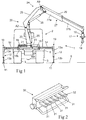
- a mobile working machine 1 is very schematically illustrated in Figs 1 and 3 .
- the mobile working machine 1 comprises a vehicle 2 provided with load-bearing vehicle wheels 3, 4 and a chassis 5 supported by the vehicle wheels.
- the vehicle 2 is a lorry provided with two rear wheels 3 and two front wheels 4, but the vehicle 2 could also be provided with a larger number of load-bearing vehicle wheels than here illustrated.
- a hydraulic crane 20 is mounted on and carried by the chassis 5. The crane 20 may be fixed directly to the chassis 5 or fixed to a subframe, which in its turn is fixed to the chassis 5.
- the mobile working machine 1 comprises two or more stabilizer legs 10 for supporting the mobile working machine against the ground 6.
- the mobile working machine 1 is provided with four stabilizer legs 10, wherein two stabilizer legs 10 are arranged on one side of the longitudinal axis of the vehicle 2 and two stabilizer legs 10 are arranged on the opposite side of the longitudinal axis of the vehicle.
- the mobile working machine could alternatively be provided with a larger or smaller number of stabilizer legs than here illustrated.
- the stabilizer legs 10 are connected to the chassis 5 of the vehicle 2.
- Each stabilizer leg 10 may comprise a foot plate 11, which is arranged at a lower end of the stabilizer leg.
- Each stabilizer leg 10 has an actuating member 12, preferably in the form of a hydraulic cylinder, by means of which the stabilizer leg is manoeuvrable between a raised inactive position, in which the stabilizer leg is out of contact with the ground 6, and an active supporting position (see Fig 1 ), in which the stabilizer leg is lowered into supporting contact with the ground. In the active supporting position, the stabilizer leg 10 is pressed against the ground 6.
- actuating member 12 preferably in the form of a hydraulic cylinder
- the actuating member 12 of each stabilizer leg 10 has the form of a hydraulic cylinder with a cylinder part 13a, which forms an upper part of the stabilizer leg, and a piston rod 13b, which forms a lower part of the stabilizer leg.
- the piston rod 13b is at its upper end fixed to a piston (not shown), which is received in the cylinder part 13a and displaceable in relation to it.
- a foot plate 11 may be fixed to the lower end of the piston rod 13b.
- each stabilizer leg 10 is mounted to an extension arm 14 at an outer end thereof.
- the extension arm 14 is telescopically extensible by means of an actuating member 15, preferably in the form of a hydraulic cylinder, in order to allow an adjustment of the horizontal extension length thereof and thereby an adjustment of the horizontal extension length L of the associated stabilizer leg 10.
- each extension arm 14 could be manually extensible.
- the stabilizer leg 10 is moveable in horizontal direction in relation to the chassis 5 of the vehicle 2 from a retracted position close to the chassis 5 to an advanced position at a distance from the chassis.
- the stabilizer leg 10 is extensible in vertical direction in relation to the extension arm 14, and thereby in relation to the chassis 5, under the effect of the actuating member 12 of the stabilizer leg 10.
- Each extension arm 14 is slidably mounted to a support beam 16a, 16b, which in its turn is connected to the chassis 5 of the vehicle 2.
- the support beams 16a of a first pair of stabilizer legs are rigidly mounted to a crane base 21 of the hydraulic crane 20, wherein these support beams 16a are connected to the chassis 5 via the crane base 21, and the support beams 16b of a second pair of stabilizer legs are rigidly mounted directly to the chassis 5 at a rear end of the vehicle 2.
- the hydraulic crane 20 comprises:
- the crane boom system 24 comprises a first liftable and lowerable crane boom 25, which is articulately connected to the column 22 in such a manner that it is pivotable in relation to the column about an essentially horizontal axis of rotation A2, and an actuating member in the form of a hydraulic cylinder 26, here denominated lifting cylinder, for lifting and lowering the first crane boom 25 in relation to the column 22.
- liftable and lowerable crane boom refers to a crane boom which can be pivoted in a vertical plane so as to thereby perform liftings and lowerings of a load carried by the crane.
- hydraulic cylinder for lifting and lowering the crane boom here refers to the hydraulic cylinder which is associated with the liftable and lowerable crane boom and which carries out the pivoting thereof in a vertical plane.
- the crane boom system 24 also comprises a liftable and lowerable second crane boom 27, which is articulately connected to the first crane boom 25 in such a manner that it is pivotable in relation to the first crane boom about an essentially horizontal axis of rotation A3, and an actuating member in the form of a hydraulic cylinder 28 for lifting and lowering of the second crane boom 27 in relation to the first crane boom 25.
- the second crane boom 27 is telescopically extensible to enable an adjustment of the extension length thereof.
- the second crane boom 27 comprises a base section 27a, through which the second crane boom 27 is articulately connected to the first crane boom 25, and a telescopic crane boom section 27b which is carried by the base section 27a and displaceable in the longitudinal direction of the base section by means of an actuating member in the form of a hydraulic cylinder 29 for adjustment of the extension length of the second crane boom 27.
- the second crane boom 27 could as an alternative be provided with two or more telescopic crane boom sections.
- the crane boom system 24 of the crane 20 is formed by the first crane boom 25 and the second crane boom 27 and the associated hydraulic cylinders 26, 28, 29.
- the crane boom system 24 of the crane 20 may as an alternative include only one liftable and lowerable crane boom or more than two liftable and lowerable crane booms articulately connected to each other.
- a load handling tool 17 provided with a rotator 18 and a lifting hook 19 is articulately connected to a boom tip at the outer end of the second crane boom 27.
- any other suitable type of load handling tool may be connected to the boom tip.
- an additional crane boom a so-called jib, may be temporarily and detachably mounted to the outer end of the second crane boom 27.
- the mobile working machine 1 comprises a manoeuvring unit 30, for instance in the form of a portable manoeuvring unit of the type illustrated in Fig 2 , with one or more manoeuvring members 31 configured to be manoeuvrable by a crane operator in order to control the movements of the crane booms 25, 27 of the crane boom system 24 and the movements of the stabilizer legs 10.
- a manoeuvring unit may be located at the mobile working machine, for instance as an integral part of the crane or the stabilizer leg equipment.
- Control signals are transmitted via cable or a wireless connection from the manoeuvring unit 30 to an electronic control device 40 (very schematically illustrated in Fig 4 ), which in its turn is configured to control the actuating members 12, 15, 23, 26, 28, 29 of the stabilizer legs 10, the extension arms 14 and the crane 20 in a conventional manner, and thereby the crane boom movements and stabilizer leg movements, on the basis of control signals from the manoeuvring unit 30 related to the manoeuvring of the manoeuvring members 31.
- the electronic control device 40 comprises a microprocessor or the similar for processing the control signals from the manoeuvring unit 30.
- At least two different operating modes are provided for the manoeuvring unit 30 and the electronic control device 40.
- the manoeuvring unit 30 and the electronic control device 40 are configured to control the actuating members 12 of the stabilizer legs 10 and the actuating members 15 of the extension arms 14 to thereby control the movements of the stabilizer legs 10.
- the manoeuvring unit 30 and the electronic control device 40 are configured to control the actuating members 23, 26, 28, 29 of the crane 20 to thereby control the movements of the crane booms 25, 27.
- the mobile working machine 1 comprises switching means 32 by means of which the crane operator may switch between the first operating mode and the second operating mode.
- the switching means 32 may for instance have the form of a maneuvering member on the manoeuvring unit 30 or a menu-guided interface with a function which can be selected by the crane operator in order to select the desired operating mode.
- the electronic control device 40 is, in a conventional manner, configured to establish a maximum allowed working pressure for the lifting cylinder 26 while taking into account the contribution to the stability of the mobile working machine 1 against tipping from each stabilizer leg 10 that is in the active supporting position.
- This maximum allowed working pressure for the lifting cylinder 26 is for instance established by the electronic control device 40 in the manner described in EP 2 298 689 B1 or in any other suitable manner.
- the mobile working machine 1 comprises a pressure sensor 41 configured to measure the hydraulic pressure on the piston side of the lifting cylinder 26.
- the electronic control device 40 is connected to the pressure sensor 41 in order to receive measuring signals from this sensor related to said hydraulic pressure.
- the electronic control device 40 continuously reads the output signal from the pressure sensor 41 and compares this output signal with the established value for the maximum allowed working pressure for the lifting cylinder 26. If the pressure sensed by the pressure sensor 41 exceeds the established maximum allowed working pressure for the lifting cylinder 26, the electronic control device 40 may be configured to stop any presently executed movement of the crane boom system 24.
- the electronic control device 40 is configured to let the maximum allowed working pressure for the lifting cylinder 26 represent the maximum allowed hydraulic pressure on the piston side of the lifting cylinder.
- the electronic control device 40 could as an alternative be configured to let the maximum allowed working pressure for the lifting cylinder 26 represent the maximum allowed differential pressure in the lifting cylinder.
- This differential pressure is defined as the hydraulic pressure on the piston side of the lifting cylinder 26 minus the hydraulic pressure on the piston rod side of the lifting cylinder divided by the cylinder ratio.
- the electronic control device 40 is also configured to receive measuring signals from a pressure sensor 42 which measures the hydraulic pressure on the piston rod side of the lifting cylinder 26 so as to thereby be able to establish the prevailing differential pressure in the lifting cylinder and compare this differential pressure with the established value of the maximum allowed working pressure for the lifting cylinder.
- working pressure as used in this description and the claims, consequently refers either to the hydraulic pressure on the piston side of the lifting cylinder 26 or the differential pressure in the lifting cylinder.
- the electronic control device 40 is preferably configured to take into account the prevailing slewing angle ⁇ of the column 22 in relation to the chassis 5 of the vehicle 2 and the horizontal extension length L of each stabilizer leg 10 that is in the active supporting position.
- the slewing angle ⁇ of the column 22 in relation to the chassis 5 is established by means of a sensor 43 which continuously senses the slewing position of the column.
- the mobile working machine 1 also comprises sensors 44 for establishing the horizontal extension length L of each stabilizer leg 10. These sensors 44 could be configured to sense the displacement position of the extension arms 14 or the displacement position of a movable part, such as a piston rod, of the actuating members 15 of the extension arms 14.
- the mobile working machine 1 comprises means 45 for providing measuring signals to the electronic control device 40 that make it possible for the electronic control device to establish when the individual stabilizer legs 10 are in the active supporting position.
- these means 45 may comprise pressure sensors for sensing the hydraulic pressure on the piston side and on the piston rod side of each one of these hydraulic cylinders 12 to thereby enable the electronic control device 40 to establish the differential pressure in each one these hydraulic cylinders 12.
- the electronic control device 40 may then, in a conventional manner, establish whether or not an individual stabilizer leg 10 is in the active supporting position while taking into account the prevailing differential pressure in the associated hydraulic cylinder 12.
- the electronic control device 40 is configured to prevent a manoeuvring of a stabilizer leg 10 from the active supporting position towards the inactive position if it is established by the electronic control device 40 that the prevailing working pressure of the lifting cylinder 26 is higher than a variable threshold value V th established by the electronic control device 40 as a value corresponding to the value of the maximum allowed working pressure for the lifting cylinder 26 that would ensue in case the stabilizer leg 10 in question is made to leave the active supporting position, wherein the electronic control device 40 is configured to enable such a manoeuvring of the stabilizer leg 10 if it is established by the electronic control device 40 that the prevailing working pressure of the lifting cylinder 26 is equal to or lower than said threshold value V th .
- the threshold value V th represents the value of the maximum allowed working pressure for the lifting cylinder 26 that would ensue if the possible contribution from the stabilizer leg 10 in question to the stability of the mobile working machine 1 against tipping is lost in the prevailing position of the crane boom system 24.
- the electronic control device 40 When the electronic control device 40 enables a manoeuvring of a stabilizer leg 10 from the active supporting position towards the inactive position, the electronic control device will control the actuating member 12 of the stabilizer leg to effect a manoeuvring of the stabilizer leg upwards away from the ground if the crane operator orders such a movement of the stabilizer leg by means of the manoeuvring unit 30.
- the electronic control device 40 When the electronic control device 40 prevents a manoeuvring of a stabilizer leg 10 from the active supporting position towards the inactive position, the electronic control device will not allow the actuating member 12 of the stabilizer leg to effect a manoeuvring of the stabilizer leg upwards away from the ground if the crane operator orders such a movement of the stabilizer leg by means of the manoeuvring unit 30.
- the electronic control device may also issue an alert to the crane operator through the manoeuvring unit or in any other suitable manner, such as for instance by means of indicator lamps etc.
- the electronic control device 40 is in the first operating mode configured to establish a threshold value V th of the above-mentioned type for each stabilizer leg 10 that is presently in the active supporting position and to compare the prevailing working pressure of the lifting cylinder 26 with each threshold value V th in order to establish which ones of these stabilizer legs 26 that at present are to be enabled to be manoeuvred from the active supporting position towards the inactive position, on condition that only one stabilizer leg is raised from the active supporting position and the other stabilizer legs remain in the active supporting position.
- the electronic control device 40 may be configured to indicate on a user display 46 the individual stabilizer legs 10 that at present are enabled to be manoeuvred from the active supporting position towards the inactive position if the other stabilizer legs remain in the active supporting position.
- each stabilizer leg 10 that is presently enabled to be raised from the active supporting position may be marked with green colour on the display 46 and each stabilizer leg that is presently prevented from being raised from the active supporting position may be marked with red colour on the display.
- the electronic control device 40 is in the first operating mode configured to establish a threshold value V th of the above-mentioned type for a stabilizer leg 10 and compare the prevailing working pressure of the lifting cylinder 26 with this threshold value V th when it has been established by the electronic control device 40, based on control signals from the manoeuvring unit 30, that the crane operator, by acting on a dedicated manoeuvring member on the manoeuvring unit 30, has ordered a manoeuvring of the stabilizer leg in question from the active supporting position towards the inactive position or selected the stabilizer leg in question for subsequent manoeuvring.
- the electronic control device 40 is configured to prevent a simultaneous manoeuvring of two or more stabilizer legs 10 from the active supporting position towards the inactive position if it is established by the electronic control device 40 that the prevailing working pressure of the lifting cylinder 26 is higher than a variable threshold value V th established by the electronic control device 40 as a value corresponding to the value of the maximum allowed working pressure for the lifting cylinder 26 that would ensue in case the stabilizer legs 10 in question are made to leave the active supporting position, wherein the electronic control device 40 is configured to enable such a manoeuvring of the stabilizer legs in question if it is established by the electronic control device 40 that the prevailing working pressure of the lifting cylinder 26 is equal to or lower than said threshold value V th .
- the threshold value V th represents the value of the maximum allowed working pressure for the lifting cylinder 26 that would ensue if the possible contribution from the stabilizer legs in question to the stability of the mobile working machine 1 against tipping is lost in the prevailing position of the crane boom system 24.
- the electronic control device 40 will establish whether or not such a manoeuvring of these stabilizer legs 10 would result in a risk for tipping of the mobile working machine 1, and the electronic control device 40 will only allow such a manoeuvring of these stabilizer legs 10 if the situation is such that there is no such risk.
- the electronic control device 40 may be implemented by one single electronic control unit or by two or more mutually cooperating electronic control units.
- the mobile working machine 1 is a lorry provided with a hydraulic loader crane in the form of a lorry crane.
- the mobile working machine of the present invention could be a lorry provided with a hydraulic loader crane in the form of a forestry crane, or any other type of loader crane.
- the mobile working machine 1 of the present invention could also be a so-called mobile crane.
Landscapes
- Engineering & Computer Science (AREA)
- Mechanical Engineering (AREA)
- Transportation (AREA)
- Jib Cranes (AREA)
Claims (15)
- Machine de travail mobile comprenant :- un châssis (5) ;- deux jambes de stabilisateur (10) ou plus pour supporter la machine de travail mobile (1) contre le sol, dans laquelle les jambes de stabilisateur (10) sont reliés au châssis (5), chaque jambe de stabilisateur (10) ayant un organe d'actionnement (12), de préférence sous la forme d'un vérin hydraulique, au moyen duquel la jambe de stabilisateur peut être manœuvré entre une position inactive, à laquelle la jambe de stabilisateur n'est pas en contact avec le sol, et une position de support active, à laquelle la jambe de stabilisateur est en contact de support avec le sol ;- une grue hydraulique (20), qui est portée par le châssis (5) et comprend :• une base de grue (21) fixée au châssis (5),• une colonne (22), qui est montée rotative sur la base de grue (21) de manière à pouvoir tourner par rapport à la base de grue autour d'un axe de rotation sensiblement vertical, et• un système de flèches de grue (24) porté par la colonne (22), dans laquelle le système de flèches de grue (24) comprend au moins une première flèche de grue pouvant être levée et abaissée (25), qui est reliée de manière articulée à la colonne (22), et un vérin hydraulique (26), ci-après désigné vérin de levage, pour lever et abaisser la première flèche de grue (25) par rapport à la colonne (22) ; et- un dispositif de commande électronique (40), qui est configuré pour établir une pression de travail admissible maximale pour le vérin de levage (26) en tenant compte de la contribution à la stabilité de la machine de travail mobile (1) contre le basculement, de chaque jambe de stabilisateur (10) qui est à la position de support active,caractérisée en ce que le dispositif de commande électronique (40) est configuré pour interdire une manœuvre d'une jambe de stabilisateur (10) depuis la position de support active vers la position inactive s'il est établi, par le dispositif de commande électronique (40), que la pression de travail régnante du vérin de levage (26) est supérieure à une valeur de seuil variable (Vth) établie par le dispositif de commande électronique (40) en tant qu'une valeur correspondant à la valeur de la pression de travail admissible maximale pour le vérin de levage (26) qui s'ensuivrait si la jambe de stabilisateur (10) en question était amené à quitter la position de support active, dans laquelle le dispositif de commande électronique (40) est configuré pour permettre une telle manœuvre de la jambe de stabilisateur (10) s'il est établi par le dispositif de commande électronique (40) que la pression de travail régnante du vérin de levage (26) est inférieure à ladite valeur de seuil (Vth).
- Machine de travail mobile selon la revendication 1, caractérisée en ce que le dispositif de commande électronique (40) est configuré pour interdire une manœuvre simultanée de deux jambes de stabilisateur (10) ou plus depuis la position de support active vers la position inactive s'il est établi, par le dispositif de commande électronique (40), que la pression de travail régnante du vérin de levage (26) est supérieure à une valeur de seuil variable (Vth) établie par le dispositif de commande électronique (40) en tant qu'une valeur correspondant à la valeur de la pression de travail admissible maximale pour le vérin de levage (26) qui s'ensuivrait si les jambes de stabilisateur (10) en question étaient amenés à quitter la position de support active, dans laquelle le dispositif de commande électronique (40) est configuré pour permettre une telle manœuvre des jambes de stabilisateur (10) en question s'il est établi par le dispositif de commande électronique (40) que la pression de travail régnante du vérin de levage (26) est inférieure à ladite valeur de seuil (Vth).
- Machine de travail mobile selon la revendication 1 ou 2, caractérisée en ce que le dispositif de commande électronique (40), lors de l'établissement de ladite valeur de seuil (Vth), est configuré pour tenir compte de l'angle de pivotement régnant (θ) de la colonne (22) par rapport au châssis (5) et de la longueur d'extension horizontale (L) de tout autre jambe de stabilisateur (10) qui est à la position de support active.
- Machine de travail mobile selon l'une quelconque des revendications 1 à 3, caractérisée en ce que :- la machine de travail mobile (1) comprend une unité de manœuvre (30) avec un ou plusieurs organes de manœuvre (31) configurés pour pouvoir être manœuvrés par un opérateur de grue afin de commander des mouvements des flèches de grue (25, 27) du système de flèches de grue (24) et des mouvements des jambes de stabilisateur (10) ;- le dispositif de commande électronique (40) est configuré pour commander des mouvements des flèches de grue et des mouvements des jambes de stabilisateur sur la base de signaux de commande provenant de l'unité de manœuvre (30) en ce qui concerne la manœuvre desdits un ou plusieurs organes de manœuvre (31) ;- au moins deux modes de fonctionnement différents sont prévus pour l'unité de manœuvre (30) et le dispositif de commande électronique (40), dans laquelle l'unité de manœuvre (30) et le dispositif de commande électronique (40), dans un premier mode de fonctionnement, sont configurés pour commander des mouvements de jambe de stabilisateur et, dans un second mode de fonctionnement, sont configurés pour commander des mouvements de flèche de grue ; et- la machine de travail mobile (1) comprend un moyen de commutation (32) au moyen duquel l'opérateur de grue peut commuter entre le premier mode de fonctionnement et le second mode de fonctionnement.
- Machine de travail mobile selon la revendication 4, caractérisée en ce que le dispositif de commande électronique (40) dans le premier mode de fonctionnement est configuré pour établir une telle valeur de seuil (Vth) pour chaque jambe de stabilisateur (10) qui est à la position de support active et pour comparer la pression de travail régnante du vérin de levage (26) à chaque valeur de seuil (Vth) afin d'établir ceux parmi ces jambes de stabilisateur (10) qui à présent doivent être autorisés à être manœuvrés depuis la position de support active vers la position inactive.
- Machine de travail mobile selon la revendication 5, caractérisée en ce que le dispositif de commande électronique (40) dans le premier mode de fonctionnement est configuré pour indiquer, sur un affichage (46), les jambes de stabilisateur (10) qui à présent doivent être autorisés à être manœuvrés depuis la position de support active vers la position inactive.
- Machine de travail mobile selon la revendication 4, caractérisée en ce que le dispositif de commande électronique (40) dans le premier mode de fonctionnement est configuré pour établir une telle valeur de seuil (Vth) pour une jambe de stabilisateur (10) et pour comparer la pression de travail régnante du vérin de levage (26) à cette valeur de seuil (Vth) lorsqu'il a été établi, par le dispositif de commande électronique (40), sur la base de signaux de commande provenant de l'unité de manœuvre (30), que l'opérateur de grue a ordonné une manœuvre de la jambe de stabilisateur en question depuis la position de support active vers la position inactive ou a sélectionné la jambe de stabilisateur en question pour une manœuvre suivante.
- Machine de travail mobile (1) selon l'une quelconque des revendications 1 à 7, caractérisée en ce que chaque jambe de stabilisateur (10) est monté sur une extrémité extérieure d'un bras d'extension s'étendant horizontalement (14), la jambe de stabilisateur (10) étant extensible par rapport au bras d'extension (14) dans une direction verticale au moyen dudit organe d'actionnement (12) de la jambe de stabilisateur, dans laquelle le bras d'extension (14) est extensible de manière télescopique afin de permettre un ajustement de la longueur d'extension horizontale de celui-ci et de ce fait un ajustement de la longueur d'extension horizontale (L) de la jambe de stabilisateur (10) associé.
- Procédé de supervision de la manœuvre de jambes de stabilisateur (10) inclus dans une machine de travail mobile (1), dans lequel la machine de travail mobile comprend :- un châssis (5) ;- deux jambes de stabilisateur (10) ou plus pour supporter la machine de travail mobile (1) contre le sol, dans lequel les jambes de stabilisateur (10) sont reliés au châssis (5), chaque jambe de stabilisateur (10) ayant un organe d'actionnement (12), de préférence sous la forme d'un vérin hydraulique, au moyen duquel la jambe de stabilisateur peut être manœuvré entre une position inactive, à laquelle la jambe de stabilisateur n'est pas en contact avec le sol, et une position de support active, à laquelle la jambe de stabilisateur est en contact de support avec le sol ; et- une grue hydraulique (20), qui est portée par le châssis (5) et comprend :• une base de grue (21) fixée au châssis (5),• une colonne (22), qui est montée rotative sur la base de grue (21) de manière à pouvoir tourner par rapport à la base de grue autour d'un axe de rotation sensiblement vertical, et• un système de flèches de grue (24) porté par la colonne (22), dans lequel le système de flèches de grue (24) comprend au moins une première flèche de grue pouvant être levée et abaissée (25), qui est reliée de manière articulée à la colonne (22), et un vérin hydraulique (26), ci-après désigné vérin de levage, pour lever et abaisser la première flèche de grue (25) par rapport à la colonne (22),dans lequel le procédé comprend les étapes suivantes effectuées au moyen d'un dispositif de commande électronique (40) de la machine de travail mobile :- l'établissement d'une pression de travail admissible maximale pour le vérin de levage (26) en tenant compte de la contribution à la stabilité de la machine de travail mobile (1) contre le basculement, de chaque jambe de stabilisateur (10) qui est à la position de support active ;- l'établissement, avant qu'une jambe de stabilisateur (10) soit autorisé à être manœuvré depuis la position de support active vers la position inactive, d'une valeur de seuil (Vth) correspondant à la valeur de la pression de travail admissible maximale pour le vérin de levage (26) qui s'ensuivrait si la jambe de stabilisateur (10) en question était amené à quitter la position de support active ;- la comparaison de la pression de travail régnante du vérin de levage (26) à ladite valeur de seuil (Vth) ;- l'interdiction d'une manœuvre de la jambe de stabilisateur (10) depuis la position de support active vers la position inactive si la pression de travail régnante du vérin de levage (26) est supérieure à ladite valeur de seuil (Vth) ; et- l'autorisation d'une manœuvre de la jambe de stabilisateur (10) depuis la position de support active vers la position inactive si la pression de travail régnante du vérin de levage (26) est inférieure à ladite valeur de seuil (Vth).
- Procédé selon la revendication 9, caractérisé en ce que le procédé comprend les étapes suivantes effectuées au moyen du dispositif de commande électronique (40) :- l'établissement, avant que deux jambes de stabilisateur (10) ou plus soient autorisés à être manœuvrés simultanément depuis la position de support active vers la position inactive, d'une valeur de seuil (Vth) correspondant à la valeur de la pression de travail admissible maximale pour le vérin de levage (26) qui s'ensuivrait si les jambes de stabilisateur (10) en question étaient amenés à quitter la position de support active ;- la comparaison de la pression de travail régnante du vérin de levage (26) à ladite valeur de seuil (Vth) ;- l'interdiction d'une manœuvre simultanée des jambes de stabilisateur (10) en question depuis la position de support active vers la position inactive si la pression de travail régnante du vérin de levage (26) est supérieure à ladite valeur de seuil (Vth) ; et- l'autorisation d'une manœuvre simultanée des jambes de stabilisateur (10) en question depuis la position de support active vers la position inactive si la pression de travail régnante du vérin de levage (26) est inférieure à ladite valeur de seuil (Vth).
- Procédé selon la revendication 9 ou 10, caractérisé en ce que le dispositif de commande électronique (40), lors de l'établissement de ladite valeur de seuil (Vth), tient compte de l'angle de pivotement régnant (θ) de la colonne (22) par rapport au châssis (5) et de la longueur d'extension horizontale (L) de tout autre jambe de stabilisateur (10) qui est à la position de support active.
- Procédé selon l'une quelconque des revendications 9 à 11, dans lequel la machine de travail mobile (1) comprend une unité de manœuvre (30) avec un ou plusieurs organes de manœuvre (31) qui peuvent être manœuvrés par un opérateur de grue afin de commander des mouvements des flèches de grue (25, 27) du système de flèches de grue (24) et des mouvements des jambes de stabilisateur (10),
caractérisé en ce que le dispositif de commande électronique (40) dans un premier mode de fonctionnement commande des mouvements de jambes de stabilisateur sur la base de signaux de commande provenant de l'unité de manœuvre (30) en ce qui concerne la manœuvre desdits un ou plusieurs organes de manœuvre (31), et, dans un second mode de fonctionnement, commande des mouvements de flèches de grue sur la base de signaux de commande provenant de l'unité de manœuvre (30) en ce qui concerne la manœuvre desdits un ou plusieurs organes de manœuvre (31), dans lequel l'opérateur de grue commute entre le premier mode de fonctionnement et le second mode de fonctionnement au moyen d'un moyen de commutation (32). - Procédé selon la revendication 12, caractérisé en ce que le dispositif de commande électronique (40) dans le premier mode de fonctionnement établit une telle valeur de seuil (Vth) pour chaque jambe de stabilisateur (10) qui est à la position de support active et compare la pression de travail régnante du vérin de levage (26) à chaque valeur de seuil (Vth) afin d'établir ceux parmi ces jambes de stabilisateur (10) qui à présent doivent être autorisés à être manœuvrés depuis la position de support active vers la position inactive.
- Procédé selon la revendication 13, caractérisé en ce que le dispositif de commande électronique (40) dans le premier mode de fonctionnement indique, sur un affichage (46), les jambes de stabilisateur (10) individuels qui à présent doivent être autorisés à être manœuvrés depuis la position de support active vers la position inactive.
- Procédé selon la revendication 12, caractérisé en ce que le dispositif de commande électronique (40) dans le premier mode de fonctionnement établit une telle valeur de seuil (Vth) pour une jambe de stabilisateur (10) et compare la pression de travail régnante du vérin de levage (26) à cette valeur de seuil (Vth) lorsqu'il a été établi, par le dispositif de commande électronique (40), sur la base de signaux de commande provenant de l'unité de manœuvre (30), que l'opérateur de grue a ordonné une manœuvre de la jambe de stabilisateur en question depuis la position de support active vers la position inactive ou a sélectionné la jambe de stabilisateur en question pour une manœuvre suivante.
Priority Applications (2)
| Application Number | Priority Date | Filing Date | Title |
|---|---|---|---|
| EP18215327.0A EP3670426B1 (fr) | 2018-12-21 | 2018-12-21 | Machine de travail mobile et procédé de supervision de man uvre de jambes de stabilisateur inclus dans une machine de travail mobile |
| US16/722,077 US11174138B2 (en) | 2018-12-21 | 2019-12-20 | Mobile working machine and method for supervising the manoeuvring of stabilizer legs included in a mobile working machine |
Applications Claiming Priority (1)
| Application Number | Priority Date | Filing Date | Title |
|---|---|---|---|
| EP18215327.0A EP3670426B1 (fr) | 2018-12-21 | 2018-12-21 | Machine de travail mobile et procédé de supervision de man uvre de jambes de stabilisateur inclus dans une machine de travail mobile |
Publications (2)
| Publication Number | Publication Date |
|---|---|
| EP3670426A1 EP3670426A1 (fr) | 2020-06-24 |
| EP3670426B1 true EP3670426B1 (fr) | 2021-10-06 |
Family
ID=64901875
Family Applications (1)
| Application Number | Title | Priority Date | Filing Date |
|---|---|---|---|
| EP18215327.0A Active EP3670426B1 (fr) | 2018-12-21 | 2018-12-21 | Machine de travail mobile et procédé de supervision de man uvre de jambes de stabilisateur inclus dans une machine de travail mobile |
Country Status (2)
| Country | Link |
|---|---|
| US (1) | US11174138B2 (fr) |
| EP (1) | EP3670426B1 (fr) |
Families Citing this family (4)
| Publication number | Priority date | Publication date | Assignee | Title |
|---|---|---|---|---|
| SE542230C2 (en) * | 2016-06-09 | 2020-03-17 | Husqvarna Ab | Improved arrangement and method for operating a hydraulically operated boom carrying a tool in a carrier |
| CN113566755B (zh) * | 2021-06-21 | 2023-09-22 | 三一重机有限公司 | 工程机械的支撑结构的位置可视化方法及工程机械 |
| CN116291191A (zh) * | 2023-03-20 | 2023-06-23 | 长沙亨特科技有限公司 | 适用于全工序的多臂协作作业车及其防倾翻方法 |
| CN119660598B (zh) * | 2024-12-19 | 2025-10-21 | 徐州重型机械有限公司 | 一种支腿互锁操纵装置及工程机械 |
Family Cites Families (7)
| Publication number | Priority date | Publication date | Assignee | Title |
|---|---|---|---|---|
| WO1995000372A1 (fr) * | 1993-06-28 | 1995-01-05 | Kabushiki Kaisha Komatsu Seisakusho | Dispositif de mise a niveau pour corps de vehicule de chantier dote de verins-supports |
| DE102004012966A1 (de) * | 2004-03-17 | 2005-10-06 | Putzmeister Ag | Mobiles Arbeitsgerät mit Stützauslegern sowie Verfahren zur Aufstellung eines solchen Geräts |
| DK1607365T3 (da) * | 2004-06-18 | 2007-09-24 | Hiab Ab | Hydraulisk kran |
| US7489098B2 (en) * | 2005-10-05 | 2009-02-10 | Oshkosh Corporation | System for monitoring load and angle for mobile lift device |
| SE534723C2 (sv) * | 2009-09-22 | 2011-11-29 | Cargotec Patenter Ab | Lastbil och förfarande för reglering av det maximalt tillåtna lyftmomentet hos en hydraulisk lastbilskran |
| DK3239092T3 (da) * | 2016-04-25 | 2019-09-02 | Cargotec Patenter Ab | Hydraulisk kran |
| SE540770C2 (en) * | 2017-03-02 | 2018-11-06 | Cargotec Patenter Ab | Load handling crane |
-
2018
- 2018-12-21 EP EP18215327.0A patent/EP3670426B1/fr active Active
-
2019
- 2019-12-20 US US16/722,077 patent/US11174138B2/en active Active
Also Published As
| Publication number | Publication date |
|---|---|
| US11174138B2 (en) | 2021-11-16 |
| EP3670426A1 (fr) | 2020-06-24 |
| US20200198943A1 (en) | 2020-06-25 |
Similar Documents
| Publication | Publication Date | Title |
|---|---|---|
| EP3257805B1 (fr) | Grue hydraulique | |
| US11174138B2 (en) | Mobile working machine and method for supervising the manoeuvring of stabilizer legs included in a mobile working machine | |
| EP3239092B1 (fr) | Grue hydraulique | |
| EP2298689B1 (fr) | Procédé et dispositif de limitation de couple d'une grue de chargement | |
| US8160786B2 (en) | Mobile crane and method for operating a mobile crane | |
| KR102096930B1 (ko) | 이동식 크레인의 안전장치 | |
| US20080019815A1 (en) | System for monitoring load and angle for mobile lift device | |
| EP3812338B1 (fr) | Camion et procédé de régulation du moment de levage maximal autorisé d'un camion grue hydraulique | |
| EP3551497B1 (fr) | Dépanneuse pouvant faire pivoter un véhicule dans l'air | |
| US20250026622A1 (en) | Safety system for working machine | |
| JP3964513B2 (ja) | トラック搭載型クレーンの安定限界信号発生装置 | |
| JP7151908B2 (ja) | 過負荷防止装置 | |
| JP4988990B2 (ja) | クレーンのジブ起伏制御装置 | |
| US20250026619A1 (en) | Safety system for working machine | |
| EP4516091B1 (fr) | Système de charge superposé pour véhicule de travail forestier | |
| JPH01256497A (ja) | 伸縮ブームを有するクレーンの吊荷地切時荷振防止装置 | |
| JP4202719B2 (ja) | 高所作業車のブーム作動規制装置 | |
| WO2025261929A1 (fr) | Chariot télescopique | |
| WO2021085569A1 (fr) | Dispositif de prévention contre les surcharges | |
| GB2197847A (en) | Agricultural material handling assembly | |
| JPH051797U (ja) | ブーム作業車の操作案内装置 | |
| JP2001278595A (ja) | 作業用車両の転倒防止装置 |
Legal Events
| Date | Code | Title | Description |
|---|---|---|---|
| PUAI | Public reference made under article 153(3) epc to a published international application that has entered the european phase |
Free format text: ORIGINAL CODE: 0009012 |
|
| STAA | Information on the status of an ep patent application or granted ep patent |
Free format text: STATUS: THE APPLICATION HAS BEEN PUBLISHED |
|
| AK | Designated contracting states |
Kind code of ref document: A1 Designated state(s): AL AT BE BG CH CY CZ DE DK EE ES FI FR GB GR HR HU IE IS IT LI LT LU LV MC MK MT NL NO PL PT RO RS SE SI SK SM TR |
|
| AX | Request for extension of the european patent |
Extension state: BA ME |
|
| STAA | Information on the status of an ep patent application or granted ep patent |
Free format text: STATUS: REQUEST FOR EXAMINATION WAS MADE |
|
| 17P | Request for examination filed |
Effective date: 20201202 |
|
| RBV | Designated contracting states (corrected) |
Designated state(s): AL AT BE BG CH CY CZ DE DK EE ES FI FR GB GR HR HU IE IS IT LI LT LU LV MC MK MT NL NO PL PT RO RS SE SI SK SM TR |
|
| RIC1 | Information provided on ipc code assigned before grant |
Ipc: B66C 23/90 20060101AFI20210325BHEP |
|
| RAP1 | Party data changed (applicant data changed or rights of an application transferred) |
Owner name: HIAB AB |
|
| GRAP | Despatch of communication of intention to grant a patent |
Free format text: ORIGINAL CODE: EPIDOSNIGR1 |
|
| STAA | Information on the status of an ep patent application or granted ep patent |
Free format text: STATUS: GRANT OF PATENT IS INTENDED |
|
| INTG | Intention to grant announced |
Effective date: 20210708 |
|
| GRAS | Grant fee paid |
Free format text: ORIGINAL CODE: EPIDOSNIGR3 |
|
| GRAA | (expected) grant |
Free format text: ORIGINAL CODE: 0009210 |
|
| STAA | Information on the status of an ep patent application or granted ep patent |
Free format text: STATUS: THE PATENT HAS BEEN GRANTED |
|
| AK | Designated contracting states |
Kind code of ref document: B1 Designated state(s): AL AT BE BG CH CY CZ DE DK EE ES FI FR GB GR HR HU IE IS IT LI LT LU LV MC MK MT NL NO PL PT RO RS SE SI SK SM TR |
|
| REG | Reference to a national code |
Ref country code: GB Ref legal event code: FG4D |
|
| REG | Reference to a national code |
Ref country code: CH Ref legal event code: EP Ref country code: AT Ref legal event code: REF Ref document number: 1436073 Country of ref document: AT Kind code of ref document: T Effective date: 20211015 |
|
| REG | Reference to a national code |
Ref country code: IE Ref legal event code: FG4D |
|
| REG | Reference to a national code |
Ref country code: DE Ref legal event code: R096 Ref document number: 602018024584 Country of ref document: DE |
|
| REG | Reference to a national code |
Ref country code: DK Ref legal event code: T3 Effective date: 20211123 |
|
| REG | Reference to a national code |
Ref country code: LT Ref legal event code: MG9D |
|
| REG | Reference to a national code |
Ref country code: NL Ref legal event code: MP Effective date: 20211006 |
|
| PG25 | Lapsed in a contracting state [announced via postgrant information from national office to epo] |
Ref country code: RS Free format text: LAPSE BECAUSE OF FAILURE TO SUBMIT A TRANSLATION OF THE DESCRIPTION OR TO PAY THE FEE WITHIN THE PRESCRIBED TIME-LIMIT Effective date: 20211006 Ref country code: LT Free format text: LAPSE BECAUSE OF FAILURE TO SUBMIT A TRANSLATION OF THE DESCRIPTION OR TO PAY THE FEE WITHIN THE PRESCRIBED TIME-LIMIT Effective date: 20211006 Ref country code: FI Free format text: LAPSE BECAUSE OF FAILURE TO SUBMIT A TRANSLATION OF THE DESCRIPTION OR TO PAY THE FEE WITHIN THE PRESCRIBED TIME-LIMIT Effective date: 20211006 Ref country code: BG Free format text: LAPSE BECAUSE OF FAILURE TO SUBMIT A TRANSLATION OF THE DESCRIPTION OR TO PAY THE FEE WITHIN THE PRESCRIBED TIME-LIMIT Effective date: 20220106 |
|
| PG25 | Lapsed in a contracting state [announced via postgrant information from national office to epo] |
Ref country code: IS Free format text: LAPSE BECAUSE OF FAILURE TO SUBMIT A TRANSLATION OF THE DESCRIPTION OR TO PAY THE FEE WITHIN THE PRESCRIBED TIME-LIMIT Effective date: 20220206 Ref country code: SE Free format text: LAPSE BECAUSE OF FAILURE TO SUBMIT A TRANSLATION OF THE DESCRIPTION OR TO PAY THE FEE WITHIN THE PRESCRIBED TIME-LIMIT Effective date: 20211006 Ref country code: PT Free format text: LAPSE BECAUSE OF FAILURE TO SUBMIT A TRANSLATION OF THE DESCRIPTION OR TO PAY THE FEE WITHIN THE PRESCRIBED TIME-LIMIT Effective date: 20220207 Ref country code: PL Free format text: LAPSE BECAUSE OF FAILURE TO SUBMIT A TRANSLATION OF THE DESCRIPTION OR TO PAY THE FEE WITHIN THE PRESCRIBED TIME-LIMIT Effective date: 20211006 Ref country code: NO Free format text: LAPSE BECAUSE OF FAILURE TO SUBMIT A TRANSLATION OF THE DESCRIPTION OR TO PAY THE FEE WITHIN THE PRESCRIBED TIME-LIMIT Effective date: 20220106 Ref country code: NL Free format text: LAPSE BECAUSE OF FAILURE TO SUBMIT A TRANSLATION OF THE DESCRIPTION OR TO PAY THE FEE WITHIN THE PRESCRIBED TIME-LIMIT Effective date: 20211006 Ref country code: LV Free format text: LAPSE BECAUSE OF FAILURE TO SUBMIT A TRANSLATION OF THE DESCRIPTION OR TO PAY THE FEE WITHIN THE PRESCRIBED TIME-LIMIT Effective date: 20211006 Ref country code: HR Free format text: LAPSE BECAUSE OF FAILURE TO SUBMIT A TRANSLATION OF THE DESCRIPTION OR TO PAY THE FEE WITHIN THE PRESCRIBED TIME-LIMIT Effective date: 20211006 Ref country code: GR Free format text: LAPSE BECAUSE OF FAILURE TO SUBMIT A TRANSLATION OF THE DESCRIPTION OR TO PAY THE FEE WITHIN THE PRESCRIBED TIME-LIMIT Effective date: 20220107 Ref country code: ES Free format text: LAPSE BECAUSE OF FAILURE TO SUBMIT A TRANSLATION OF THE DESCRIPTION OR TO PAY THE FEE WITHIN THE PRESCRIBED TIME-LIMIT Effective date: 20211006 |
|
| REG | Reference to a national code |
Ref country code: DE Ref legal event code: R097 Ref document number: 602018024584 Country of ref document: DE |
|
| PG25 | Lapsed in a contracting state [announced via postgrant information from national office to epo] |
Ref country code: SM Free format text: LAPSE BECAUSE OF FAILURE TO SUBMIT A TRANSLATION OF THE DESCRIPTION OR TO PAY THE FEE WITHIN THE PRESCRIBED TIME-LIMIT Effective date: 20211006 Ref country code: SK Free format text: LAPSE BECAUSE OF FAILURE TO SUBMIT A TRANSLATION OF THE DESCRIPTION OR TO PAY THE FEE WITHIN THE PRESCRIBED TIME-LIMIT Effective date: 20211006 Ref country code: RO Free format text: LAPSE BECAUSE OF FAILURE TO SUBMIT A TRANSLATION OF THE DESCRIPTION OR TO PAY THE FEE WITHIN THE PRESCRIBED TIME-LIMIT Effective date: 20211006 Ref country code: MC Free format text: LAPSE BECAUSE OF FAILURE TO SUBMIT A TRANSLATION OF THE DESCRIPTION OR TO PAY THE FEE WITHIN THE PRESCRIBED TIME-LIMIT Effective date: 20211006 Ref country code: EE Free format text: LAPSE BECAUSE OF FAILURE TO SUBMIT A TRANSLATION OF THE DESCRIPTION OR TO PAY THE FEE WITHIN THE PRESCRIBED TIME-LIMIT Effective date: 20211006 Ref country code: CZ Free format text: LAPSE BECAUSE OF FAILURE TO SUBMIT A TRANSLATION OF THE DESCRIPTION OR TO PAY THE FEE WITHIN THE PRESCRIBED TIME-LIMIT Effective date: 20211006 |
|
| REG | Reference to a national code |
Ref country code: CH Ref legal event code: PL |
|
| PLBE | No opposition filed within time limit |
Free format text: ORIGINAL CODE: 0009261 |
|
| STAA | Information on the status of an ep patent application or granted ep patent |
Free format text: STATUS: NO OPPOSITION FILED WITHIN TIME LIMIT |
|
| 26N | No opposition filed |
Effective date: 20220707 |
|
| REG | Reference to a national code |
Ref country code: BE Ref legal event code: MM Effective date: 20211231 |
|
| REG | Reference to a national code |
Ref country code: AT Ref legal event code: UEP Ref document number: 1436073 Country of ref document: AT Kind code of ref document: T Effective date: 20211006 |
|
| PG25 | Lapsed in a contracting state [announced via postgrant information from national office to epo] |
Ref country code: LU Free format text: LAPSE BECAUSE OF NON-PAYMENT OF DUE FEES Effective date: 20211221 Ref country code: IE Free format text: LAPSE BECAUSE OF NON-PAYMENT OF DUE FEES Effective date: 20211221 Ref country code: AL Free format text: LAPSE BECAUSE OF FAILURE TO SUBMIT A TRANSLATION OF THE DESCRIPTION OR TO PAY THE FEE WITHIN THE PRESCRIBED TIME-LIMIT Effective date: 20211006 |
|
| PG25 | Lapsed in a contracting state [announced via postgrant information from national office to epo] |
Ref country code: SI Free format text: LAPSE BECAUSE OF FAILURE TO SUBMIT A TRANSLATION OF THE DESCRIPTION OR TO PAY THE FEE WITHIN THE PRESCRIBED TIME-LIMIT Effective date: 20211006 Ref country code: FR Free format text: LAPSE BECAUSE OF NON-PAYMENT OF DUE FEES Effective date: 20211231 Ref country code: BE Free format text: LAPSE BECAUSE OF NON-PAYMENT OF DUE FEES Effective date: 20211231 |
|
| PG25 | Lapsed in a contracting state [announced via postgrant information from national office to epo] |
Ref country code: LI Free format text: LAPSE BECAUSE OF NON-PAYMENT OF DUE FEES Effective date: 20211231 Ref country code: CH Free format text: LAPSE BECAUSE OF NON-PAYMENT OF DUE FEES Effective date: 20211231 |
|
| PG25 | Lapsed in a contracting state [announced via postgrant information from national office to epo] |
Ref country code: CY Free format text: LAPSE BECAUSE OF FAILURE TO SUBMIT A TRANSLATION OF THE DESCRIPTION OR TO PAY THE FEE WITHIN THE PRESCRIBED TIME-LIMIT Effective date: 20211006 |
|
| PG25 | Lapsed in a contracting state [announced via postgrant information from national office to epo] |
Ref country code: HU Free format text: LAPSE BECAUSE OF FAILURE TO SUBMIT A TRANSLATION OF THE DESCRIPTION OR TO PAY THE FEE WITHIN THE PRESCRIBED TIME-LIMIT; INVALID AB INITIO Effective date: 20181221 |
|
| GBPC | Gb: european patent ceased through non-payment of renewal fee |
Effective date: 20221221 |
|
| PG25 | Lapsed in a contracting state [announced via postgrant information from national office to epo] |
Ref country code: GB Free format text: LAPSE BECAUSE OF NON-PAYMENT OF DUE FEES Effective date: 20221221 |
|
| PG25 | Lapsed in a contracting state [announced via postgrant information from national office to epo] |
Ref country code: MK Free format text: LAPSE BECAUSE OF FAILURE TO SUBMIT A TRANSLATION OF THE DESCRIPTION OR TO PAY THE FEE WITHIN THE PRESCRIBED TIME-LIMIT Effective date: 20211006 |
|
| PG25 | Lapsed in a contracting state [announced via postgrant information from national office to epo] |
Ref country code: TR Free format text: LAPSE BECAUSE OF FAILURE TO SUBMIT A TRANSLATION OF THE DESCRIPTION OR TO PAY THE FEE WITHIN THE PRESCRIBED TIME-LIMIT Effective date: 20211006 |
|
| REG | Reference to a national code |
Ref country code: DE Ref legal event code: R081 Ref document number: 602018024584 Country of ref document: DE Owner name: HIAB AB, SE Free format text: FORMER OWNER: HIAB AB, KISTA, SE |
|
| PG25 | Lapsed in a contracting state [announced via postgrant information from national office to epo] |
Ref country code: MT Free format text: LAPSE BECAUSE OF FAILURE TO SUBMIT A TRANSLATION OF THE DESCRIPTION OR TO PAY THE FEE WITHIN THE PRESCRIBED TIME-LIMIT Effective date: 20211006 |
|
| PGFP | Annual fee paid to national office [announced via postgrant information from national office to epo] |
Ref country code: AT Payment date: 20251218 Year of fee payment: 8 |
|
| PGFP | Annual fee paid to national office [announced via postgrant information from national office to epo] |
Ref country code: IT Payment date: 20251218 Year of fee payment: 8 Ref country code: DK Payment date: 20251222 Year of fee payment: 8 |
|
| PGFP | Annual fee paid to national office [announced via postgrant information from national office to epo] |
Ref country code: DE Payment date: 20251229 Year of fee payment: 8 |