EP3670432B1 - Support de récipient pour dispositif de remplissage à jet libre - Google Patents
Support de récipient pour dispositif de remplissage à jet libre Download PDFInfo
- Publication number
- EP3670432B1 EP3670432B1 EP19217403.5A EP19217403A EP3670432B1 EP 3670432 B1 EP3670432 B1 EP 3670432B1 EP 19217403 A EP19217403 A EP 19217403A EP 3670432 B1 EP3670432 B1 EP 3670432B1
- Authority
- EP
- European Patent Office
- Prior art keywords
- container
- filling
- compensation
- container holder
- support
- Prior art date
- Legal status (The legal status is an assumption and is not a legal conclusion. Google has not performed a legal analysis and makes no representation as to the accuracy of the status listed.)
- Active
Links
Images


Classifications
-
- B—PERFORMING OPERATIONS; TRANSPORTING
- B67—OPENING, CLOSING OR CLEANING BOTTLES, JARS OR SIMILAR CONTAINERS; LIQUID HANDLING
- B67C—CLEANING, FILLING WITH LIQUIDS OR SEMILIQUIDS, OR EMPTYING, OF BOTTLES, JARS, CANS, CASKS, BARRELS, OR SIMILAR CONTAINERS, NOT OTHERWISE PROVIDED FOR; FUNNELS
- B67C3/00—Bottling liquids or semiliquids; Filling jars or cans with liquids or semiliquids using bottling or like apparatus; Filling casks or barrels with liquids or semiliquids
- B67C3/02—Bottling liquids or semiliquids; Filling jars or cans with liquids or semiliquids using bottling or like apparatus
- B67C3/22—Details
- B67C3/24—Devices for supporting or handling bottles
- B67C3/242—Devices for supporting or handling bottles engaging with bottle necks
-
- B—PERFORMING OPERATIONS; TRANSPORTING
- B65—CONVEYING; PACKING; STORING; HANDLING THIN OR FILAMENTARY MATERIAL
- B65B—MACHINES, APPARATUS OR DEVICES FOR, OR METHODS OF, PACKAGING ARTICLES OR MATERIALS; UNPACKING
- B65B3/00—Packaging plastic material, semiliquids, liquids or mixed solids and liquids, in individual containers or receptacles, e.g. bags, sacks, boxes, cartons, cans, or jars
- B65B3/04—Methods of, or means for, filling the material into the containers or receptacles
-
- B—PERFORMING OPERATIONS; TRANSPORTING
- B65—CONVEYING; PACKING; STORING; HANDLING THIN OR FILAMENTARY MATERIAL
- B65B—MACHINES, APPARATUS OR DEVICES FOR, OR METHODS OF, PACKAGING ARTICLES OR MATERIALS; UNPACKING
- B65B43/00—Forming, feeding, opening or setting-up containers or receptacles in association with packaging
- B65B43/42—Feeding or positioning bags, boxes, or cartons in the distended, opened, or set-up state; Feeding preformed rigid containers, e.g. tins, capsules, glass tubes, glasses, to the packaging position; Locating containers or receptacles at the filling position; Supporting containers or receptacles during the filling operation
- B65B43/46—Feeding or positioning bags, boxes, or cartons in the distended, opened, or set-up state; Feeding preformed rigid containers, e.g. tins, capsules, glass tubes, glasses, to the packaging position; Locating containers or receptacles at the filling position; Supporting containers or receptacles during the filling operation using grippers
-
- B—PERFORMING OPERATIONS; TRANSPORTING
- B65—CONVEYING; PACKING; STORING; HANDLING THIN OR FILAMENTARY MATERIAL
- B65B—MACHINES, APPARATUS OR DEVICES FOR, OR METHODS OF, PACKAGING ARTICLES OR MATERIALS; UNPACKING
- B65B43/00—Forming, feeding, opening or setting-up containers or receptacles in association with packaging
- B65B43/42—Feeding or positioning bags, boxes, or cartons in the distended, opened, or set-up state; Feeding preformed rigid containers, e.g. tins, capsules, glass tubes, glasses, to the packaging position; Locating containers or receptacles at the filling position; Supporting containers or receptacles during the filling operation
- B65B43/54—Means for supporting containers or receptacles during the filling operation
-
- B—PERFORMING OPERATIONS; TRANSPORTING
- B67—OPENING, CLOSING OR CLEANING BOTTLES, JARS OR SIMILAR CONTAINERS; LIQUID HANDLING
- B67C—CLEANING, FILLING WITH LIQUIDS OR SEMILIQUIDS, OR EMPTYING, OF BOTTLES, JARS, CANS, CASKS, BARRELS, OR SIMILAR CONTAINERS, NOT OTHERWISE PROVIDED FOR; FUNNELS
- B67C3/00—Bottling liquids or semiliquids; Filling jars or cans with liquids or semiliquids using bottling or like apparatus; Filling casks or barrels with liquids or semiliquids
- B67C3/02—Bottling liquids or semiliquids; Filling jars or cans with liquids or semiliquids using bottling or like apparatus
- B67C3/22—Details
- B67C3/225—Means for filling simultaneously, e.g. in a rotary filling apparatus or multiple rows of containers
Definitions
- the invention relates to a container holder for a filling device for filling containers with a filling product, preferably for free jet filling of containers with a beverage in a beverage bottling plant.
- the invention also relates to a filling device equipped with such container holders.
- the container to be filled is positioned below a filling element, which then introduces the liquid filling product essentially vertically downwards into the container mouth.
- the container mouth is not close to the filling element but is spaced apart by a certain vertical distance so that the air displaced by the filling product can escape into the environment.
- a possible solution to the problem is to increase the performance of the rotary machine by making it larger overall, ie providing it with a larger pitch circle and additional filling elements.
- the maintenance effort increases, as does the required installation space.
- the DE 10 2011 016 760 A1 proposes moving the filling element and the container to be filled relative to one another to compensate for the deflection of the filling jet so that the filling jet enters the container essentially centrally through the container opening.
- a disadvantage of compensating for the deflection of the filling jet by a relative adjustment of the container carrier and the filling element is that either the container carrier or the filling elements of the system have to be redesigned in a not inconsiderable way in order to be movable or tiltable relative to one another without impairing their functionality . If the compensation is made by adjusting the filling elements, it must be ensured that the filling behavior does not change as a result. If, on the other hand, the compensation is made by repositioning the container carriers, it must be ensured that the containers can continue to be gripped, held and transferred to subsequent stations. Retrofitting existing rotary machines is therefore not easily possible.
- the JP 2009-269660 A describes a filling device in a rotary design with gripping devices for holding the containers to be filled.
- the EP 2 295 352 A2 describes a gripping unit for holding and moving articles.
- An object of the invention is to provide an improved container holder for a filling device for filling containers with a filling product and an improved filling device, in particular to simplify retrofitting an existing filling device with container holders that are designed to compensate for any filling jet deflection.
- the container holder according to the invention is intended for a filling device for filling containers with a filling product.
- the container holder is used particularly preferably in free-jet fillers for bottling beverages.
- the container holder has a holding portion configured to receive and hold a container, and a main support attachable or attached to the filling device.
- the container holder also has a compensation support which can be adjusted in a compensation direction relative to the main support and on which the holding section is attached.
- the term “adjustable” means that the position and/or orientation of the compensation support can be changed relative to the main support, for example it can be pivoted and/or displaced.
- the compensation carrier is designed to be linearly displaceable relative to the main carrier. It should be noted that the compensation support and the holding section can be formed as separate components, integrally or in one piece.
- Container holders of this construction can contribute to an increase in the performance of a filling device equipped with them, since the adjustability of the main support, and thus of the holding section, can compensate for a filling jet deflection. If the filling jet is significantly deflected, for example when the output of the filling machine is increased due to an increase in the speed of a filler carousel, the container holder can be switched to a compensation state. This applies in particular to the filling of comparatively small-volume containers, where an increase in performance is less limited by the maximum flow rate of the filling elements and more by the rotational speed of the filler carousel.
- Existing filling devices can easily be retrofitted with the improved container holders, since the main beam can be connected to the existing attachment sections for conventional container holders. Constructions relating to the inlet and outlet, the container transfer, the filling elements, etc. do not have to be fundamentally changed, but at most adapted.
- the holding section preferably comprises two clamping arms which are pivotably mounted on the compensation support and/or are made of a flexible material.
- the clamping arms are preferably biased into a preferred compressed position.
- a retaining spring can be provided to generate the pretension, which is arranged between the clamping arms and fastened to them in such a way that they are pressed or pulled into the preferred position.
- the container holder preferably has one or more guide elements, with the compensation support being displaceable along the compensation direction, guided by the guide elements.
- the guide elements are preferably attached to the main beam.
- the compensation direction corresponds to the radial direction of the filler carousel or at least has a non-zero vector component in this direction.
- the compensation carrier is from a normal state, in which the mouth of a container held therein is located substantially centrally below the outlet of an associated filling element of the filling device, to at least one compensation state, in which the mouth of the container is displaced relative to the outlet of the filling element, and vice reverse adjustable.
- the compensation state thus denotes a decentralized mounting of the container relative to the outlet of the filling element. In this way, a centrifugal force-related deflection of the filling jet is compensated.
- several compensation states can be provided in order to be able to compensate for different degrees of the deflection of the filling beam. In particular, a continuous transition from the normal state to a maximum compensation state and vice versa can be implemented.
- the container holder can also be converted into the normal state defined above, it can also be used in a conventional filling device without compensation or in the case of a sufficiently low output, with which there is no or only an insignificant filling jet deflection. This can be the case, for example, when filling comparatively large containers, such as 2-liter bottles, if the capacity of the filling system is primarily limited by the volume throughput of the filling element.
- the compensation carrier is preferably biased into one of the states, such as the compensation state, which means that any means for actively adjusting the compensation carrier only have to operate in one direction, while the compensation carrier returns to the initial state by itself.
- a mechanically simple and reliable implementation of such a preload can be accomplished by means of one or more compensation springs.
- One end of such a compensation spring can, for example, be attached to the compensation support, while the other end is attached to the guide element or main support.
- the container holder has a locking device that is set up to fix the compensation carrier in the normal state and/or in the compensation state. This primarily means fixing or locking relative to the main support. In this way, the state in question is safely maintained. If the container holder can be fixed in the normal state, this can easily and reliably between one
- Normal operation can be switched without compensation and a compensating operation.
- the locking device can preferably be switched under program control in order to avoid manual operator intervention.
- a mechanically simple and reliable realization of the locking device can be achieved by means of at least one hook which is attached pivotably to the main support and/or compensation support and can be brought into engagement with and released from a counterpart on the other support.
- the container holder preferably has one or more stops, preferably adjustable, for defining the normal state and/or a compensation state.
- the end position i.e. the maximum compensation state
- the container holder preferably has an adjustment section which is set up to adjust the position of the compensation carrier.
- the actuating section can position the compensation carrier, i.e. change its position or state, in a mechanical, electrical, magnetic, hydraulic, pneumatic or other manner.
- the positioning takes place mechanically, in that the adjusting section comprises a roller which is set up to interact with a curved segment of the filling device. In this way, the transfer from the normal state to the compensation state and vice versa takes place particularly reliably, in a structurally simple manner that can be easily retrofitted.
- the above object is also achieved by a filling device with one or more container holders according to the embodiment variants described.
- the filling device is set up here to move containers by means of the container holders during filling with a filling product along a trajectory which is curved at least in sections. In the curved sections, a filling jet deflection can occur due to centrifugal force, which can be compensated for by the container holders according to the invention.
- the filling device is a rotary machine with a filler carousel, which has the container holders and transports them along a circular segment while the containers are being filled, with the compensation direction in this case corresponding to the radial direction of the filler carousel or at least a non-vanishing vector component in this direction having.
- the filling device preferably has a curve segment which, together with the positioning sections of the container holders, is set up in such a way that in the area of the container transfer to the holding section and/or container delivery to a subsequent station, the compensation carrier is caused by a curve of the curve segment that acts on the roller in is brought to the normal state while the compensation carrier is in a compensation state during filling.
- a filling device equipped with compensable container holders can have a controller/logic that determines the correct compensation state, for example, calculates it as a function of the rotational speed of the filler carousel, and controls it. Such a control can also be set up to indicate whether the increase in performance due to the eccentric filling prevents an enlargement of the filler pitch circle. The eccentric filling can lead to an increase in the performance of the filling device.
- the Figure 1a shows a schematic plan view of a container holder 10.
- the container holder 10 is set up to hold a container 1 (cf. Figure 1b ), hold it securely for filling and hand it over to a subsequent station or transport facility after filling.
- the container 1 is held at least during filling by a filling element 2 (cf. Figure 1b ) along a trajectory that is curved at least in sections.
- the container 1 is preferably held by the container holder 10 at its mouth or in the region of the mouth.
- the container 1, such as a bottle to be filled with a drink is thus preferably held in a hanging position by the container holder 10.
- there is no restriction with regard to the type of holder as long as the containers 1 can be picked up, held securely and released again.
- the container holder 10 is particularly preferably part of a rotary machine with a filler carousel, which has a plurality of container holders 10 at equal intervals and is transported along a circular segment, while one or more containers 1 are simultaneously filled by associated filling elements 2 .
- the container holder 10 has a holding section 11 which, according to the present exemplary embodiment, comprises two clamping arms 11a, 11b which are attached to a carrier which is referred to herein as a compensation carrier 12.
- the clamping arms 11a, 11b are preferably mounted pivotably on the compensation support 12, and they can be pretensioned by means of a retaining spring 13 in a preferred compressed position.
- This way lets For example, a container 1 can be clamped in the holding section 11 with slight pressure, in that the clamping arms 11a, 11b are pushed apart a little by the container 1 itself and the retaining spring 13 exerts sufficient pressure on the container 1 to hold it.
- the clamping arms 11a, 11b can be made of a flexible material, thus having their own flexibility, so that a retaining spring 13 can optionally be dispensed with.
- the holding section 11 can be realized in a different way. In the simplest case, the holding section 11 only has a recess into which the containers 1 are hung.
- the holding section 11 and the compensation carrier 12 can be formed as separate components, integrally or in one piece.
- the compensation carrier 12 is adjustable, so that the holding section 11 can be shifted by a certain amount.
- the compensation support 12 can be displaced along a compensation direction K, guided by guide elements 14 .
- the compensation direction K corresponds to the radial direction of the filler carousel or at least has a non-vanishing vector component in this direction.
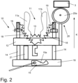
- FIGS. 1a and 1b show the container holder 10 in a normal state, in which the mouth of a container 1 held therein is substantially centrally located under the outlet of an associated filling element 2 during filling.
- the normal state thus designates a position in which there is no compensation for any filling jet deflection.
- the container holder 10 can therefore also be used in a conventional filling device without compensation or in the case of a sufficiently low output, with which there is no or only an insignificant filling jet deflection. This can be the case, for example, when filling comparatively large containers 1, such as 2-liter bottles, if the capacity of the filling system is primarily limited by the volume throughput of the filling element 2.
- a locking device 15 which fixes the compensation carrier 12 .
- the locking device 15 comprises a hook 15a which is pivotally attached to a support, referred to herein as the main support 16.
- the hook 15a interacts with a counterpart, for example provided or attached to the compensation support 12, together.
- the locking device 15 can additionally or alternatively be set up to lock one or more compensation states.
- the locking device 15 can preferably be switched under program control in order to avoid manual operator intervention.
- the Control of the locking device 15 is in the figure 1 indicated by a pneumatic cylinder 17.
- the locking device 15 can be actuated by a rod switch, by an electric motor, hydraulically or in some other way.
- the main support 16 is provided for attaching the container holder 10 to a filling device, for example for attachment to corresponding receptacles of a filler carousel.
- the container holder 10 can be released by releasing the locking device 15, as in FIG figure 2 shown, are converted into a compensation state.
- the compensation carrier 12 moves outwards along the guide elements 14, ie in the direction in which the filling jet is deflected, as a result of which the container 1 held by the container holder 10 is brought to a decentralized position. Ie the container mouth is offset to the outlet of the filling element 2, as from the Figure 3b emerges. In this way, the deflection of the filling jet caused by centrifugal force is compensated.
- the transition between the normal state and the compensation state can be realized by a spring-controlled mechanism, as it is from the Figures 1a , 2 and 3a emerges. It should be pointed out that, of course, several compensation states can be provided in order to be able to compensate for different degrees of the deflection of the filling beam. In particular, a continuous transition from the normal state to a maximum compensation state according to the Figure 3a will be realized.
- the spring controlled mechanism includes one or more compensating springs 18 which bias the compensating beam 12 into the compensating state.
- the compensation springs 18 are attached to the compensation support 12 and each to an end section of a corresponding guide element 14 .
- the holding section 11 is thus biased to an eccentric position below the filling element 2 .
- the end position, ie the maximum compensation state, can be defined by a stop 19, which is preferably adjustable.
- the stop 19 can be implemented, for example, by two lock nuts, each of which engages in a threaded section of the guide elements 14 .
- the adjusting section 20 comprises, for example, a roller 20a which is provided with a cam segment 3 (cf. figure 2 ) of the filling device interacts.
- the compensation carrier 12 is pressed into the normal state below the filling element 2 by a curve of the curve segment 3, which acts on the roller 20a, against the pretensioning effect of the compensation springs 18.
- the actuation of the compensation carrier 12 is realized by a combination of a cam control and a spring-controlled mechanism.
- the transition between the normal state and the at least one compensation state can be implemented in a technically simple and reliable manner.
- the compensation carrier 12 can also be actuated in other ways, for example by means of a pressure damper, by an electric motor, hydraulically, pneumatically, magnetically, etc.
- the container holder 10 may have a support 21 behind the compensating beam 12, which stabilizes the movable holding portion 11 in the normal state when pushed to the normal state by the roller 20a.
- the support 21 thus serves as a stop on the normal state side, which mechanically defines and stabilizes the correct position of the compensation carrier 12 in the normal state.
- the support 21 can be attached to the main beam 16 in order to ensure a minimum distance between the main beam 16 and the compensation beam 12 .
- a filling device equipped with compensable container holders 10 can have a controller/logic which determines and controls the correct compensation state. Such a control can also be set up to indicate whether the increase in performance due to the eccentric filling prevents an enlargement of the filler pitch circle. The off-centre filling can lead to an increase in the performance of the filling device through skilful utilization or adaptation to the physical conditions.
- the container holders 10 presented here can contribute to an increase in the performance of a filling device equipped therewith without increasing the number of filling elements 2 . This applies in particular to the filling of comparatively small-volume containers, in which an increase in performance is less limited by the maximum flow rate of the filling elements 2, but rather by the rotational speed of the filler carousel.
- Existing filling devices can be retrofitted with the container holders 10 in a simple manner. Constructions relating to the inlet and outlet, the container transfer, the filling elements 2, etc. do not have to be fundamentally changed but at best adapted, although even an adaptation can be omitted in many cases. Furthermore, the container holders 10 allow deactivation of the compensation for lower powers.
Landscapes
- Engineering & Computer Science (AREA)
- Mechanical Engineering (AREA)
- Filling Of Jars Or Cans And Processes For Cleaning And Sealing Jars (AREA)
- Supplying Of Containers To The Packaging Station (AREA)
- Basic Packing Technique (AREA)
Claims (12)
- Support de récipient (10) destiné à un dispositif de remplissage pour remplir des récipients (1) avec un produit de remplissage, de préférence pour le remplissage par jet libre de récipients (1) avec une boisson dans une ligne d'embouteillage de boissons, dans lequel le support de récipient (10) présente :une section de retenue (11), qui est adaptée pour recevoir et maintenir un récipient (1) ;un support principal (16), qui peut être monté sur le dispositif de remplissage ; etun support de compensation (12), qui peut être réglé, de préférence qui peut être déplacé de manière linéaire, dans un sens de compensation (K) par rapport au support principal (16) et sur lequel est monté la section de retenue (11) ;caractérisé en ce quele support de compensation (12) peut être ajusté à partir d'un état normal, dans lequel l'embouchure d'un récipient (1) maintenu à l'intérieur est situé sensiblement au centre sous l'orifice d'évacuation d'un organe de remplissage (2) correspondant du dispositif de remplissage, dans au moins un état de compensation, dans lequel l'embouchure du récipient (1) est décalée par rapport à l'orifice d'évacuation de l'organe de remplissage (2), et vice versa, etle support de récipient (10) présente en outre un dispositif de verrouillage (15), qui est adapté pour fixer le support de compensation (12) dans l'état normal et/ou l'état de compensation.
- Support de récipient (10) selon la revendication 1, caractérisé en ce que la section de retenue (11) comprend deux bras de serrage (11a, 11b), qui sont montés de manière pivotante sur le support de compensation (12) et/ou fabriqués à partir d'un matériau souple, dans lequel les bras de serrage (11a, 11b) sont précontraints de préférence dans une position préférentielle comprimée.
- Support de récipient (10) selon la revendication 1 ou 2, caractérisé en ce que celui-ci présente un ou plusieurs éléments de guidage (14), dans lequel le support de compensation (12) peut être déplacé de manière guidée par les éléments de guidage (14) suivant le sens de compensation (K).
- Support de récipient (10) selon l'une quelconque des revendications 1 à 3, caractérisé en ce que le support de compensation (12) est précontraint dans l'un desdits états, de préférence l'état de compensation.
- Support de récipient (10) selon la revendication 4, caractérisé en ce que celui-ci présente un ou plusieurs ressorts de compensation (18), qui précontraignent le support de compensation (12) dans l'état de compensation ou l'état normal.
- Support de récipient (10) selon l'une quelconque des revendications précédentes, caractérisé en ce que le dispositif de verrouillage (15) peut être commuté par programmation.
- Support de récipient (10) selon la revendication 6, caractérisé en ce que le dispositif de verrouillage (15) comprend au moins un crochet (15a), qui est monté de manière pivotante sur le support principal (16) et/ou sur le support de compensation (12) et qui avec une contre-pièce peut être mis en prise avec l'autre support et peut être détaché de celui-ci.
- Support de récipient (10) selon l'une quelconque des revendications précédentes, caractérisé en ce que celui-ci présente une ou plusieurs butées (19, 21), de préférence réglables, pour définir l'état normal et/ou un état de compensation.
- Support de récipient (10) selon l'une quelconque des revendications précédentes, caractérisé en ce que celui-ci présente une section de réglage (20), qui est adaptée pour régler la position du support de compensation (12), dans lequel la section de réglage (20) comprend un rouleau (20a), qui est adapté pour interagir avec un segment de courbure (3) du dispositif de remplissage.
- Dispositif de remplissage doté d'un ou de plusieurs supports de récipient (10) selon l'une quelconque des revendications précédentes, qui est adapté pour déplacer des récipients (1) au moyen de supports de récipient (10) pendant le remplissage avec un produit de remplissage suivant une trajectoire, qui est incurvée au moins par endroits.
- Dispositif de remplissage selon la revendication 10, caractérisé en ce que celui-ci est une machine à plateaux tournants avec un carrousel de remplissage, qui présente les supports de récipient (10) et transporte ceux-ci pendant le remplissage du récipient (1) suivant un segment circulaire, dans lequel le sens de compensation (K) correspond au sens radial du carrousel de remplissage ou présente au moins une composante vectorielle non nulle dans ledit sens.
- Dispositif de remplissage selon la revendication 10 ou 11 doté d'un ou de plusieurs supports de récipient (10) selon la revendication 10, caractérisé en ce que le dispositif de remplissage présente un segment de courbure (3), qui est adapté conjointement avec les sections de réglage (20) des supports de récipient (10) de telle manière que dans la zone où le récipient est transféré sur la section de retenue (11) et/ou le récipient est déposé sur une station suivante, le support de compensation (12) par une courbure du segment de courbure (3), qui agit sur le rouleau (20a), est amené dans l'état normal, pendant que le support de compensation (12) lors du remplissage du récipient (1) se situe dans l'état de compensation.
Priority Applications (1)
| Application Number | Priority Date | Filing Date | Title |
|---|---|---|---|
| SI201930482T SI3670432T1 (sl) | 2018-12-18 | 2019-12-18 | Nosilec posode za polnilno napravo s prostim curkom |
Applications Claiming Priority (1)
| Application Number | Priority Date | Filing Date | Title |
|---|---|---|---|
| DE102018132635.1A DE102018132635A1 (de) | 2018-12-18 | 2018-12-18 | Behälterhalterung für einen Freistrahlfüller |
Publications (2)
| Publication Number | Publication Date |
|---|---|
| EP3670432A1 EP3670432A1 (fr) | 2020-06-24 |
| EP3670432B1 true EP3670432B1 (fr) | 2023-03-01 |
Family
ID=68944575
Family Applications (1)
| Application Number | Title | Priority Date | Filing Date |
|---|---|---|---|
| EP19217403.5A Active EP3670432B1 (fr) | 2018-12-18 | 2019-12-18 | Support de récipient pour dispositif de remplissage à jet libre |
Country Status (5)
| Country | Link |
|---|---|
| US (1) | US11247890B2 (fr) |
| EP (1) | EP3670432B1 (fr) |
| CN (1) | CN111333003B (fr) |
| DE (1) | DE102018132635A1 (fr) |
| SI (1) | SI3670432T1 (fr) |
Family Cites Families (27)
| Publication number | Priority date | Publication date | Assignee | Title |
|---|---|---|---|---|
| US3105526A (en) * | 1961-01-13 | 1963-10-01 | Fmc Corp | Can track |
| CH608294A5 (fr) * | 1976-11-30 | 1978-12-29 | Mettler Instrumente Ag | |
| US4363338A (en) * | 1980-09-08 | 1982-12-14 | Brown Albert M | Liquid filling machine |
| US4588001A (en) * | 1983-06-23 | 1986-05-13 | The Kartridg Pak Co. | Rotary filling apparatus and method |
| DE19533462A1 (de) * | 1995-09-09 | 1997-03-13 | Ruediger Haaga Gmbh | Vorrichtung zum Füllen von Behältern mit einer zu Schaumbildung neigenden Flüssigkeit |
| ITBO20020523A1 (it) * | 2002-08-05 | 2004-02-06 | Azionaria Costruzioni Acma Spa | Macchina per il riempimento di contenitori. |
| DE102004004331B3 (de) * | 2004-01-29 | 2005-09-15 | Khs Maschinen- Und Anlagenbau Ag | Verfahren zum Heißabfüllen eines flüssigen Füllgutes in Flaschen oder dergleichen Behälter sowie Füllmaschine zum Durchführen des Verfahrens |
| DE102004042516B4 (de) * | 2004-09-02 | 2006-10-05 | Khs Ag | Verfahren zum Freistrahlfüllen von Flaschen oder dergleichen Behälter mit einem flüssigen Füllgut sowie Füllmaschine zum Durchführen dieses Verfahrens |
| DE102006017706A1 (de) * | 2006-04-15 | 2007-10-25 | Khs Ag | Füllelemente sowie Füllmaschine mit einem Füllelement |
| DE102006028266A1 (de) * | 2006-06-20 | 2007-12-27 | Khs Ag | Verfahren zum Behandeln von Behältern sowie Behälterbehandlungsmaschine |
| JP4877586B2 (ja) * | 2006-07-06 | 2012-02-15 | 株式会社湯山製作所 | 薬剤収納取出装置 |
| DE102008018516A1 (de) * | 2008-04-12 | 2009-10-15 | Krones Ag | Vorrichtung zum Befüllen von Behältnissen |
| JP5058874B2 (ja) * | 2008-05-09 | 2012-10-24 | 三菱重工食品包装機械株式会社 | ロータリー式フィラ |
| DE102008029208A1 (de) * | 2008-06-19 | 2009-12-24 | Krones Ag | Freistrahlfüllsystem |
| DE102009043984A1 (de) * | 2009-09-11 | 2011-03-17 | Krones Ag | Greifeinheit zum Haltern und Bewegen von Artikeln |
| DE102011010955B4 (de) * | 2011-02-10 | 2013-01-31 | Khs Gmbh | Verschiebbare Transportsterne |
| DE102011016760A1 (de) | 2011-04-12 | 2012-10-18 | Khs Gmbh | Verfahren sowie Füllmaschine zum Freistrahlfüllen von Flaschen oder dergleichen Behältern |
| DE102011007280A1 (de) * | 2011-04-13 | 2012-10-18 | Krones Aktiengesellschaft | Behälterbehandlungsmaschine und Verfahren zur Behälterbehandlung |
| DE102012000758A1 (de) * | 2012-01-18 | 2013-07-18 | Khs Gmbh | Anlage sowie Verfahren zum Füllen von Behältern |
| KR101508058B1 (ko) * | 2013-08-14 | 2015-04-07 | 최훈 | 페트병 회전이송장치 |
| EP2930139B1 (fr) * | 2014-04-08 | 2017-02-01 | Sidel S.p.a. Con Socio Unico | Machine de remplissage de récipients avec un dispositif de pesage amélioré et procédé de pesage associé |
| EP2944450A1 (fr) * | 2014-05-13 | 2015-11-18 | Discma AG | Machine rotative comprenant des premières et des secondes stations tournant autour d'un axe principal unique |
| DE102015110765A1 (de) * | 2015-07-03 | 2017-01-05 | Krones Ag | Vorrichtung zum Transport eines Behälters |
| WO2017097787A1 (fr) * | 2015-12-07 | 2017-06-15 | Nestec S.A. | Appareil et procédé servant à remplir et sceller des contenants |
| CN106183406A (zh) * | 2016-08-29 | 2016-12-07 | 江苏华宇印涂设备集团有限公司 | 包括移动平台保险机构的印铁机 |
| CN207375729U (zh) * | 2017-08-31 | 2018-05-18 | 广州达意隆包装机械股份有限公司 | 灌装机及其称重组件 |
| DE102017130036A1 (de) * | 2017-12-14 | 2019-06-19 | Krones Ag | Vorrichtung zum Transportieren eines Behälters |
-
2018
- 2018-12-18 DE DE102018132635.1A patent/DE102018132635A1/de not_active Withdrawn
-
2019
- 2019-12-18 SI SI201930482T patent/SI3670432T1/sl unknown
- 2019-12-18 EP EP19217403.5A patent/EP3670432B1/fr active Active
- 2019-12-18 US US16/719,556 patent/US11247890B2/en not_active Expired - Fee Related
- 2019-12-18 CN CN201911309298.3A patent/CN111333003B/zh not_active Expired - Fee Related
Also Published As
| Publication number | Publication date |
|---|---|
| SI3670432T1 (sl) | 2023-08-31 |
| CN111333003A (zh) | 2020-06-26 |
| EP3670432A1 (fr) | 2020-06-24 |
| CN111333003B (zh) | 2022-05-31 |
| US11247890B2 (en) | 2022-02-15 |
| US20200189897A1 (en) | 2020-06-18 |
| DE102018132635A1 (de) | 2020-06-18 |
Similar Documents
| Publication | Publication Date | Title |
|---|---|---|
| EP3440007B1 (fr) | Système de remplissage de boissons pour le remplissage de récipients | |
| DE69405650T2 (de) | Sternrad mit Justiervorrichtung für unterschiedlich geformte Behälter | |
| DE69104583T2 (de) | Greifklemme und damit ausgerüstete behandlungsmaschine für gegenstände, insbesondere flaschen. | |
| EP2295352B1 (fr) | Dispositif de prise pour tenir et déplacer des articles | |
| EP2858793B1 (fr) | Dispositif de préhension | |
| DE102008022848B4 (de) | PET-Flaschengreifer | |
| EP3592676B1 (fr) | Dispositif de préhension et de transport | |
| EP1935811B1 (fr) | Convoyeur pneumatique pour récipients | |
| EP2046675A1 (fr) | Machine de traitement pour bouteilles ou récipients similaires | |
| EP1980509B1 (fr) | Machine de traitement de récipients | |
| DE102020131105A1 (de) | Vorrichtung zum linearen Transportieren von Behältern | |
| EP2110346B1 (fr) | Agencement et procédé de transport et de distribution synchrone de récipients | |
| EP3912939A1 (fr) | Dispositif de serrage et dispositif de manutention de conteneurs | |
| EP2882673A1 (fr) | Préhenseur de récipients ainsi qu'élément de transport pourvu de tels préhenseurs de récipients | |
| EP3912937B1 (fr) | Dispositif de définition d'une position de bras de pince et dispositif de transport de récipients | |
| EP4129888B1 (fr) | Dispositif de commande d'une position de levage d'un élément de levage, dispositif de manutention de récipients et procédé de réglage d'un point de transition d'une came de commande | |
| EP3670432B1 (fr) | Support de récipient pour dispositif de remplissage à jet libre | |
| EP3938298B1 (fr) | Dispositif de transport et procédé pour le transport de récipients en circulation autour d'un axe de machine vertical | |
| DE10122752B4 (de) | Antrieb für höhenverstellbare Behälterträger an Abfüllmaschinen | |
| DE102015224973A1 (de) | Behälterbehandlungsmaschine | |
| EP4169871B1 (fr) | Dispositif d'alimentation de bouchons à un dispositif de fermeture dans une installation de remplissage de boissons | |
| EP2210829B1 (fr) | Transporteur à courroies incliné | |
| EP4240678A1 (fr) | Dispositif de transport pour le transport de récipients | |
| DE102020128058A1 (de) | Transportstern zum Transportieren von Behältern | |
| EP1717179B1 (fr) | Dispositif pour stabiliser des produits imprimés transportés en flux le long d'un trajet de transport, suspendus dans des pinces d'un dispositif de transport |
Legal Events
| Date | Code | Title | Description |
|---|---|---|---|
| PUAI | Public reference made under article 153(3) epc to a published international application that has entered the european phase |
Free format text: ORIGINAL CODE: 0009012 |
|
| STAA | Information on the status of an ep patent application or granted ep patent |
Free format text: STATUS: THE APPLICATION HAS BEEN PUBLISHED |
|
| AK | Designated contracting states |
Kind code of ref document: A1 Designated state(s): AL AT BE BG CH CY CZ DE DK EE ES FI FR GB GR HR HU IE IS IT LI LT LU LV MC MK MT NL NO PL PT RO RS SE SI SK SM TR |
|
| AX | Request for extension of the european patent |
Extension state: BA ME |
|
| STAA | Information on the status of an ep patent application or granted ep patent |
Free format text: STATUS: REQUEST FOR EXAMINATION WAS MADE |
|
| 17P | Request for examination filed |
Effective date: 20201123 |
|
| RBV | Designated contracting states (corrected) |
Designated state(s): AL AT BE BG CH CY CZ DE DK EE ES FI FR GB GR HR HU IE IS IT LI LT LU LV MC MK MT NL NO PL PT RO RS SE SI SK SM TR |
|
| GRAP | Despatch of communication of intention to grant a patent |
Free format text: ORIGINAL CODE: EPIDOSNIGR1 |
|
| STAA | Information on the status of an ep patent application or granted ep patent |
Free format text: STATUS: GRANT OF PATENT IS INTENDED |
|
| RIC1 | Information provided on ipc code assigned before grant |
Ipc: B67C 3/24 20060101AFI20220818BHEP |
|
| INTG | Intention to grant announced |
Effective date: 20220920 |
|
| GRAS | Grant fee paid |
Free format text: ORIGINAL CODE: EPIDOSNIGR3 |
|
| GRAA | (expected) grant |
Free format text: ORIGINAL CODE: 0009210 |
|
| STAA | Information on the status of an ep patent application or granted ep patent |
Free format text: STATUS: THE PATENT HAS BEEN GRANTED |
|
| AK | Designated contracting states |
Kind code of ref document: B1 Designated state(s): AL AT BE BG CH CY CZ DE DK EE ES FI FR GB GR HR HU IE IS IT LI LT LU LV MC MK MT NL NO PL PT RO RS SE SI SK SM TR |
|
| REG | Reference to a national code |
Ref country code: GB Ref legal event code: FG4D Free format text: NOT ENGLISH |
|
| REG | Reference to a national code |
Ref country code: CH Ref legal event code: EP Ref country code: AT Ref legal event code: REF Ref document number: 1550859 Country of ref document: AT Kind code of ref document: T Effective date: 20230315 |
|
| REG | Reference to a national code |
Ref country code: DE Ref legal event code: R096 Ref document number: 502019007082 Country of ref document: DE |
|
| REG | Reference to a national code |
Ref country code: IE Ref legal event code: FG4D Free format text: LANGUAGE OF EP DOCUMENT: GERMAN |
|
| REG | Reference to a national code |
Ref country code: LT Ref legal event code: MG9D |
|
| P01 | Opt-out of the competence of the unified patent court (upc) registered |
Effective date: 20230523 |
|
| REG | Reference to a national code |
Ref country code: NL Ref legal event code: MP Effective date: 20230301 |
|
| PG25 | Lapsed in a contracting state [announced via postgrant information from national office to epo] |
Ref country code: RS Free format text: LAPSE BECAUSE OF FAILURE TO SUBMIT A TRANSLATION OF THE DESCRIPTION OR TO PAY THE FEE WITHIN THE PRESCRIBED TIME-LIMIT Effective date: 20230301 Ref country code: NO Free format text: LAPSE BECAUSE OF FAILURE TO SUBMIT A TRANSLATION OF THE DESCRIPTION OR TO PAY THE FEE WITHIN THE PRESCRIBED TIME-LIMIT Effective date: 20230601 Ref country code: LV Free format text: LAPSE BECAUSE OF FAILURE TO SUBMIT A TRANSLATION OF THE DESCRIPTION OR TO PAY THE FEE WITHIN THE PRESCRIBED TIME-LIMIT Effective date: 20230301 Ref country code: LT Free format text: LAPSE BECAUSE OF FAILURE TO SUBMIT A TRANSLATION OF THE DESCRIPTION OR TO PAY THE FEE WITHIN THE PRESCRIBED TIME-LIMIT Effective date: 20230301 Ref country code: HR Free format text: LAPSE BECAUSE OF FAILURE TO SUBMIT A TRANSLATION OF THE DESCRIPTION OR TO PAY THE FEE WITHIN THE PRESCRIBED TIME-LIMIT Effective date: 20230301 Ref country code: ES Free format text: LAPSE BECAUSE OF FAILURE TO SUBMIT A TRANSLATION OF THE DESCRIPTION OR TO PAY THE FEE WITHIN THE PRESCRIBED TIME-LIMIT Effective date: 20230301 |
|
| PG25 | Lapsed in a contracting state [announced via postgrant information from national office to epo] |
Ref country code: SE Free format text: LAPSE BECAUSE OF FAILURE TO SUBMIT A TRANSLATION OF THE DESCRIPTION OR TO PAY THE FEE WITHIN THE PRESCRIBED TIME-LIMIT Effective date: 20230301 Ref country code: PL Free format text: LAPSE BECAUSE OF FAILURE TO SUBMIT A TRANSLATION OF THE DESCRIPTION OR TO PAY THE FEE WITHIN THE PRESCRIBED TIME-LIMIT Effective date: 20230301 Ref country code: NL Free format text: LAPSE BECAUSE OF FAILURE TO SUBMIT A TRANSLATION OF THE DESCRIPTION OR TO PAY THE FEE WITHIN THE PRESCRIBED TIME-LIMIT Effective date: 20230301 Ref country code: GR Free format text: LAPSE BECAUSE OF FAILURE TO SUBMIT A TRANSLATION OF THE DESCRIPTION OR TO PAY THE FEE WITHIN THE PRESCRIBED TIME-LIMIT Effective date: 20230602 Ref country code: FI Free format text: LAPSE BECAUSE OF FAILURE TO SUBMIT A TRANSLATION OF THE DESCRIPTION OR TO PAY THE FEE WITHIN THE PRESCRIBED TIME-LIMIT Effective date: 20230301 |
|
| PG25 | Lapsed in a contracting state [announced via postgrant information from national office to epo] |
Ref country code: SM Free format text: LAPSE BECAUSE OF FAILURE TO SUBMIT A TRANSLATION OF THE DESCRIPTION OR TO PAY THE FEE WITHIN THE PRESCRIBED TIME-LIMIT Effective date: 20230301 Ref country code: RO Free format text: LAPSE BECAUSE OF FAILURE TO SUBMIT A TRANSLATION OF THE DESCRIPTION OR TO PAY THE FEE WITHIN THE PRESCRIBED TIME-LIMIT Effective date: 20230301 Ref country code: PT Free format text: LAPSE BECAUSE OF FAILURE TO SUBMIT A TRANSLATION OF THE DESCRIPTION OR TO PAY THE FEE WITHIN THE PRESCRIBED TIME-LIMIT Effective date: 20230703 Ref country code: EE Free format text: LAPSE BECAUSE OF FAILURE TO SUBMIT A TRANSLATION OF THE DESCRIPTION OR TO PAY THE FEE WITHIN THE PRESCRIBED TIME-LIMIT Effective date: 20230301 Ref country code: CZ Free format text: LAPSE BECAUSE OF FAILURE TO SUBMIT A TRANSLATION OF THE DESCRIPTION OR TO PAY THE FEE WITHIN THE PRESCRIBED TIME-LIMIT Effective date: 20230301 |
|
| PG25 | Lapsed in a contracting state [announced via postgrant information from national office to epo] |
Ref country code: SK Free format text: LAPSE BECAUSE OF FAILURE TO SUBMIT A TRANSLATION OF THE DESCRIPTION OR TO PAY THE FEE WITHIN THE PRESCRIBED TIME-LIMIT Effective date: 20230301 Ref country code: IS Free format text: LAPSE BECAUSE OF FAILURE TO SUBMIT A TRANSLATION OF THE DESCRIPTION OR TO PAY THE FEE WITHIN THE PRESCRIBED TIME-LIMIT Effective date: 20230701 |
|
| REG | Reference to a national code |
Ref country code: DE Ref legal event code: R097 Ref document number: 502019007082 Country of ref document: DE |
|
| PLBE | No opposition filed within time limit |
Free format text: ORIGINAL CODE: 0009261 |
|
| STAA | Information on the status of an ep patent application or granted ep patent |
Free format text: STATUS: NO OPPOSITION FILED WITHIN TIME LIMIT |
|
| PG25 | Lapsed in a contracting state [announced via postgrant information from national office to epo] |
Ref country code: DK Free format text: LAPSE BECAUSE OF FAILURE TO SUBMIT A TRANSLATION OF THE DESCRIPTION OR TO PAY THE FEE WITHIN THE PRESCRIBED TIME-LIMIT Effective date: 20230301 |
|
| PGFP | Annual fee paid to national office [announced via postgrant information from national office to epo] |
Ref country code: SI Payment date: 20231117 Year of fee payment: 5 Ref country code: IT Payment date: 20231110 Year of fee payment: 5 Ref country code: FR Payment date: 20231108 Year of fee payment: 5 Ref country code: DE Payment date: 20231031 Year of fee payment: 5 |
|
| 26N | No opposition filed |
Effective date: 20231204 |
|
| REG | Reference to a national code |
Ref country code: CH Ref legal event code: PL |
|
| PG25 | Lapsed in a contracting state [announced via postgrant information from national office to epo] |
Ref country code: LU Free format text: LAPSE BECAUSE OF NON-PAYMENT OF DUE FEES Effective date: 20231218 |
|
| PG25 | Lapsed in a contracting state [announced via postgrant information from national office to epo] |
Ref country code: MC Free format text: LAPSE BECAUSE OF FAILURE TO SUBMIT A TRANSLATION OF THE DESCRIPTION OR TO PAY THE FEE WITHIN THE PRESCRIBED TIME-LIMIT Effective date: 20230301 |
|
| GBPC | Gb: european patent ceased through non-payment of renewal fee |
Effective date: 20231218 |
|
| REG | Reference to a national code |
Ref country code: BE Ref legal event code: MM Effective date: 20231231 |
|
| PG25 | Lapsed in a contracting state [announced via postgrant information from national office to epo] |
Ref country code: MC Free format text: LAPSE BECAUSE OF FAILURE TO SUBMIT A TRANSLATION OF THE DESCRIPTION OR TO PAY THE FEE WITHIN THE PRESCRIBED TIME-LIMIT Effective date: 20230301 Ref country code: LU Free format text: LAPSE BECAUSE OF NON-PAYMENT OF DUE FEES Effective date: 20231218 |
|
| REG | Reference to a national code |
Ref country code: IE Ref legal event code: MM4A |
|
| PG25 | Lapsed in a contracting state [announced via postgrant information from national office to epo] |
Ref country code: IE Free format text: LAPSE BECAUSE OF NON-PAYMENT OF DUE FEES Effective date: 20231218 |
|
| PG25 | Lapsed in a contracting state [announced via postgrant information from national office to epo] |
Ref country code: GB Free format text: LAPSE BECAUSE OF NON-PAYMENT OF DUE FEES Effective date: 20231218 |
|
| PG25 | Lapsed in a contracting state [announced via postgrant information from national office to epo] |
Ref country code: BE Free format text: LAPSE BECAUSE OF NON-PAYMENT OF DUE FEES Effective date: 20231231 |
|
| PG25 | Lapsed in a contracting state [announced via postgrant information from national office to epo] |
Ref country code: CH Free format text: LAPSE BECAUSE OF NON-PAYMENT OF DUE FEES Effective date: 20231231 |
|
| PG25 | Lapsed in a contracting state [announced via postgrant information from national office to epo] |
Ref country code: IE Free format text: LAPSE BECAUSE OF NON-PAYMENT OF DUE FEES Effective date: 20231218 Ref country code: GB Free format text: LAPSE BECAUSE OF NON-PAYMENT OF DUE FEES Effective date: 20231218 Ref country code: CH Free format text: LAPSE BECAUSE OF NON-PAYMENT OF DUE FEES Effective date: 20231231 Ref country code: BE Free format text: LAPSE BECAUSE OF NON-PAYMENT OF DUE FEES Effective date: 20231231 |
|
| PG25 | Lapsed in a contracting state [announced via postgrant information from national office to epo] |
Ref country code: BG Free format text: LAPSE BECAUSE OF FAILURE TO SUBMIT A TRANSLATION OF THE DESCRIPTION OR TO PAY THE FEE WITHIN THE PRESCRIBED TIME-LIMIT Effective date: 20230301 |
|
| PG25 | Lapsed in a contracting state [announced via postgrant information from national office to epo] |
Ref country code: BG Free format text: LAPSE BECAUSE OF FAILURE TO SUBMIT A TRANSLATION OF THE DESCRIPTION OR TO PAY THE FEE WITHIN THE PRESCRIBED TIME-LIMIT Effective date: 20230301 |
|
| REG | Reference to a national code |
Ref country code: DE Ref legal event code: R119 Ref document number: 502019007082 Country of ref document: DE |
|
| PG25 | Lapsed in a contracting state [announced via postgrant information from national office to epo] |
Ref country code: CY Free format text: LAPSE BECAUSE OF FAILURE TO SUBMIT A TRANSLATION OF THE DESCRIPTION OR TO PAY THE FEE WITHIN THE PRESCRIBED TIME-LIMIT; INVALID AB INITIO Effective date: 20191218 |
|
| PG25 | Lapsed in a contracting state [announced via postgrant information from national office to epo] |
Ref country code: HU Free format text: LAPSE BECAUSE OF FAILURE TO SUBMIT A TRANSLATION OF THE DESCRIPTION OR TO PAY THE FEE WITHIN THE PRESCRIBED TIME-LIMIT; INVALID AB INITIO Effective date: 20191218 |
|
| PG25 | Lapsed in a contracting state [announced via postgrant information from national office to epo] |
Ref country code: DE Free format text: LAPSE BECAUSE OF NON-PAYMENT OF DUE FEES Effective date: 20250701 |
|
| PG25 | Lapsed in a contracting state [announced via postgrant information from national office to epo] |
Ref country code: IT Free format text: LAPSE BECAUSE OF NON-PAYMENT OF DUE FEES Effective date: 20241218 |
|
| PG25 | Lapsed in a contracting state [announced via postgrant information from national office to epo] |
Ref country code: FR Free format text: LAPSE BECAUSE OF NON-PAYMENT OF DUE FEES Effective date: 20241231 |
|
| REG | Reference to a national code |
Ref country code: SI Ref legal event code: KO00 Effective date: 20241219 |
|
| PG25 | Lapsed in a contracting state [announced via postgrant information from national office to epo] |
Ref country code: TR Free format text: LAPSE BECAUSE OF FAILURE TO SUBMIT A TRANSLATION OF THE DESCRIPTION OR TO PAY THE FEE WITHIN THE PRESCRIBED TIME-LIMIT Effective date: 20230301 |
|
| REG | Reference to a national code |
Ref country code: AT Ref legal event code: MM01 Ref document number: 1550859 Country of ref document: AT Kind code of ref document: T Effective date: 20241218 |
|
| PG25 | Lapsed in a contracting state [announced via postgrant information from national office to epo] |
Ref country code: AT Free format text: LAPSE BECAUSE OF NON-PAYMENT OF DUE FEES Effective date: 20241218 |
|
| PGFP | Annual fee paid to national office [announced via postgrant information from national office to epo] |
Ref country code: AT Payment date: 20260410 Year of fee payment: 5 |