EP4169871B1 - Dispositif d'alimentation de bouchons à un dispositif de fermeture dans une installation de remplissage de boissons - Google Patents
Dispositif d'alimentation de bouchons à un dispositif de fermeture dans une installation de remplissage de boissons Download PDFInfo
- Publication number
- EP4169871B1 EP4169871B1 EP22203085.0A EP22203085A EP4169871B1 EP 4169871 B1 EP4169871 B1 EP 4169871B1 EP 22203085 A EP22203085 A EP 22203085A EP 4169871 B1 EP4169871 B1 EP 4169871B1
- Authority
- EP
- European Patent Office
- Prior art keywords
- closures
- stop
- closure
- stopper
- closure channel
- Prior art date
- Legal status (The legal status is an assumption and is not a legal conclusion. Google has not performed a legal analysis and makes no representation as to the accuracy of the status listed.)
- Active
Links
Images
Classifications
-
- B—PERFORMING OPERATIONS; TRANSPORTING
- B67—OPENING, CLOSING OR CLEANING BOTTLES, JARS OR SIMILAR CONTAINERS; LIQUID HANDLING
- B67B—APPLYING CLOSURE MEMBERS TO BOTTLES JARS, OR SIMILAR CONTAINERS; OPENING CLOSED CONTAINERS
- B67B3/00—Closing bottles, jars or similar containers by applying caps
- B67B3/02—Closing bottles, jars or similar containers by applying caps by applying flanged caps, e.g. crown caps, and securing by deformation of flanges
- B67B3/06—Feeding caps to capping heads
-
- B—PERFORMING OPERATIONS; TRANSPORTING
- B67—OPENING, CLOSING OR CLEANING BOTTLES, JARS OR SIMILAR CONTAINERS; LIQUID HANDLING
- B67B—APPLYING CLOSURE MEMBERS TO BOTTLES JARS, OR SIMILAR CONTAINERS; OPENING CLOSED CONTAINERS
- B67B3/00—Closing bottles, jars or similar containers by applying caps
- B67B3/02—Closing bottles, jars or similar containers by applying caps by applying flanged caps, e.g. crown caps, and securing by deformation of flanges
- B67B3/06—Feeding caps to capping heads
- B67B3/064—Feeding caps to capping heads from a hopper
- B67B3/0645—Feeding caps to capping heads from a hopper with means for orientating the caps to a position ready to be applied to the container
Definitions
- the present invention relates to a device for supplying closures to a closer for closing containers with the closures, preferably in a beverage filling plant.
- Closers for applying closures to filled containers are known, for example for applying crown caps or screw caps to bottles in beverage filling plants.
- a closer in rotary design has a rotating carousel, on the circumference of which several closure elements and associated container holders are mounted.
- the container to be closed is transferred to a container holder of the carousel via a container feed, for example via a transfer star, and is closed with a closure by means of an associated closure element during transport along a partial circle of the carousel.
- a closer is used, for example, in the EN 10 2012 103 518 A1 described.
- the closures are usually fed to the closer via a closure channel, through which the closures are either transferred directly to the closer or to a so-called pick wheel, which is arranged in front of the actual closer and brings the closures provided by the closure channel in a continuous stream to the required pitch/timing.
- a provision device including, for example, sorting and/or aligning the closures.
- the provision device is usually arranged above the closer and is connected to the closer via the closure channel, in which the sorted and correctly aligned closures are guided. The closures then slide off the conveyor belt due to their own weight or driven in some other way.
- Provision device for the capper Such a system consisting of capper, provision device and closure channel is, for example, based on the EN 10 2018 129 548 A1 out.
- a gap occurs in the sequence of containers to be closed.
- the closure channel should not pass a closure to the closer, as the excess closure may otherwise cause malfunctions in the closer.
- the stopper comprises an actuatable finger which, when necessary, reaches into the closure channel and stops the closure feed.
- a closure feeder with a stopper or a device according to the preamble of claim 1 is known, for example, from EN 10 2012 110 102 A1 described.
- Such a stopper causes an abrupt stop, which, due to the inertia of the subsequent closures, creates a high back pressure on the front closures, which can damage or deform the closures. Such damage or deformation of the closures can lead to closures jamming in the closure channel, thus hindering the restart of the closure feed, or causing malfunctions in the closure machine. Manual intervention by an operator is required, which reduces system productivity.
- An object of the present invention is to provide an improved device for feeding closures to a capper, preferably in a beverage filling plant, in particular to reduce any damage/deformation of the closures and/or to optimize the plant productivity.
- the device according to the invention serves to supply closures to a closure device for closing containers with the closures.
- the device is particularly preferably used in a beverage filling plant, for example for filling water (still or carbonated), soft drinks, beer, wine, juice, smoothies, dairy products, mixed drinks and the like.
- the device comprises a closure channel for feeding the closures to the closer, wherein the closure channel is arranged and set up such that the closures are guided and transported along a transport path defined by the closure channel.
- the closure channel thus has a shape and dimension corresponding to the closures, seen in cross-section perpendicular to the transport path, so that the closures can move in the closure channel along the defined transport path in the direction of the closer.
- the device further comprises a stop device with a stopper which is designed according to the invention to slow down and stop the supply of closures to the closer in the closure channel along a braking path.
- the stopper is a dampening stopper in that it slows down the closures along a certain distance and thus gently stops the closure supply.
- the braking path naturally defines a distance greater than zero.
- the stopper is designed for braking along the braking path, i.e. minimal and unintentional deformations, vibrations and the like due to the material or design, as well as any design-related play between components are not included.
- the stopper preferably comprises a pin-, pencil- or finger-like stop element, the stopper in this case being designed to move the stop element into the closure channel in such a way that the supply of closures to the closer can be blocked. If the supply of closures to the closer is to be interrupted, the stop device moves the stop element into the closure channel, for example by means of a corresponding trigger device, so that the flow of closures to the closer is blocked.
- the trigger device can
- the stop element can be actuated electrically, magnetically, hydraulically, pneumatically or purely mechanically. To ensure the braking distance, the stop element is preferably mounted so that it can move along the locking channel. In this way, a mechanically simple and reliable stopper is created.
- the stopper can have a rotatably mounted stop wheel with several engagement sections arranged on the circumference, which can each be brought into engagement with a closure in the closure channel to stop the supply of closures to the closer.
- the stop wheel is preferably a gear wheel with a pitch that matches the closures in the closure channel, the engagement sections being formed by the teeth of the gear wheel.
- the stop device preferably has a braking device connected to the stop wheel, which is designed to stop rotation of the stop wheel, i.e. to block it or to brake it to a standstill.
- the stop wheel is rotatably mounted on the braking device, wherein the gentle braking of the closure feed is preferably achieved by the braking device braking the stop wheel in a controlled manner over a certain angle of rotation that corresponds to the braking distance.
- the braking device comprising a speed-adjustable electric motor, for example a synchronous motor, and a corresponding control.
- the stopper is mounted so that it can move along the braking path.
- the stopper for example a bearing for the stop wheel or stop element, can be installed so that it can move using a guide.
- the guide is preferably attached to a holder that is stationary relative to the locking channel.
- the stopping device has a damping device which is designed to dampen a displacement of the stopper along the braking path, whereby the braking of the closure feed takes place particularly gently.
- the damping device can be formed by an elongated, elastic part, for example a spring, which is attached to the holder on one side and to the stopper on the other side.
- the damping device can be designed in a mechanically simple manner. and reliable manner.
- the damping device can work pneumatically or magnetically.
- a pneumatic cylinder can be installed between the bracket and the stopper, which can also dampen or gently slow down the movement of the closures.
- the closure channel is preferably arranged and set up in such a way that the closures can be transported along the transport path due to gravity, with the closure channel running at least partially inclined (relative to the horizontal) and/or vertically for this purpose.
- the transport of the closures in the closure channel can be achieved without a dedicated drive.
- the braking distance preferably has a vertical (vector) component, which makes the construction particularly simple and reliable in mechanical engineering terms. The braking distance can run essentially entirely in the direction of gravity.
- the propulsion of the closures in the closure channel towards the capper can be generated or supported in another way, for example by a magnetic unit in the case of metallic closures such as crown caps.
- the closure channel is designed so that there is always a maximum of exactly one closure at a given position on the transport path.
- the closures move one after the other in the closure channel along the transport path, which simplifies the controlled feeding to the closer and the separation.
- the above-mentioned object is further achieved by a system or a device with a closer for closing containers, a device connected thereto for supplying closures to the closer according to one of the embodiments set out above and a provision device which is designed to provide closures for closing the containers and to transfer them to the device for supplying closures.
- the closer can have a pick wheel onto which the closures are placed via the closure chute.
- the pick wheel is a star-wheel-shaped feed device which brings the closures provided by the closure chute in a continuous stream to the pitch or timing specified in the closer. If necessary, a pick wheel can be dispensed with by placing the closures from the closure chute onto a transfer platform, for example.
- the transfer platform is set up in such a way that the closures placed on it can be picked up and further processed by the closer's closing elements.
- the supply device is designed to sort and/or align the closures.
- the supply device can have a closure reservoir, preferably of cylindrical shape, which is designed to accommodate a large number of closures.
- the closure reservoir can have an agitator for mixing and/or conveying and/or aligning the closures.
- Possible closures include, for example, crown caps, screw caps or corks.
- the stop device is designed to slow down the supply of closures to the closer in the closure channel along the braking path during the transition from an operating state in which the closures are to be fed to the closer to a stop state in which the closure supply to the closer is to be interrupted.
- the transition from the operating state to the stop state and vice versa takes place when required, for example in the event of a technical fault in the closer. In this way, it can be effectively prevented that in the event of a gap in the sequence of containers to be closed, the closure channel passes superfluous closures to the closer, where the closures could otherwise cause faults.
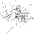
- the Figure 1 shows a device 1 with a closer 10 for closing containers (not shown in the figures) with corresponding closures 2 (cf. Figures 2a, 2b , 3 and 4 ) and a device 20 for supplying closures 2 to the closer 10.
- the device 1 is preferably a part of a filling system for filling containers with a filling product.
- the device 1 is used in a beverage filling system, for example for filling water (still or carbonated), soft drinks, beer, wine, juice, smoothies, dairy products, mixed drinks and the like.
- closures 2 that have been sorted and aligned with respect to their spatial position are fed to the closer 10 from a supply device 30 arranged above the closer 10.
- the supply device 30 for example, closures 2 that arrive unsorted are sorted.
- the supply device 30 can have a closure reservoir 31, preferably of cylindrical shape, which is designed to accommodate a large number of closures 2.
- the closure reservoir 31 can have an agitator for mixing, conveying and, if necessary, aligning the closures 2.
- Closures 2 may include, for example, crown caps, screw caps or corks.
- the device 20 for feeding closures 2 with a closure channel 21 is arranged between the supply device 30 and the closer 10.
- the closure channel 21 is connected to the lower area of the closure reservoir 31 in such a way that the closures 2 can be fed from the closure reservoir 31 into the closure channel 21.
- the closure channel 21 is designed in such a way that the closures 2 are guided along a transport path predetermined by the closure channel 21, whereby they are particularly preferably conveyed along the transport path by their own weight, i.e. due to gravity.
- the closure channel 21 is mostly inclined relative to the horizontal and runs vertically in sections.
- the closure channel 21 has a shape and dimension corresponding to the closures 2, seen in cross-section perpendicular to the transport path, so that at a given position on the transport path there is always a maximum of exactly one closure 2.
- the closures 2 move in the closure channel 21 one behind the other along the transport path, with the closure channel 21 being designed like a slide, so that the closures 2 slide down the closure channel 21 in the direction of the closer 10 after leaving the closure reservoir 31.
- a transfer segment 22 is connected to the closure channel 21 in the area of the closer 10, by means of which the closures 2 are brought into a horizontal orientation and transferred from the closure channel 21 to the closer 10.
- the closures 2 are transferred by the transfer segment 22 to a pick wheel 11, which is conceptually considered to be a component of the closer 10.
- the pick wheel 11 is a star-wheel-shaped feed device which brings the closures 2 provided by the transfer segment 22 in a continuous stream to the pitch or timing specified in the closer 2.
- the pick wheel 11 transfers the closures 2 accordingly to closing elements 12, which are arranged on the circumference of a carousel and are set up to close the containers with one closure 2 each.
- a pick wheel 11 can be dispensed with by placing the closures 2 from the transfer segment 22 onto a transfer platform, for example.
- the transfer platform is set up in such a way that the closures 2 placed thereon can be picked up and further processed by the closing elements 12 of the closer 10.
- the device 20 for supplying closures 2 further comprises a stop device 23 which is designed to interrupt the flow of closures 2 from the closure channel 21 to the closer 10 if necessary, for example in the event of a technical fault in the closer 2.
- the stop device 23 is preferably arranged on a vertical section of the closure channel 21, tending to be in the lower region of the closure channel 21.
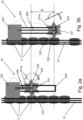
- FIG. 2a shows a state of the stop device 23 during regular operation, also referred to herein as "operating state”
- the Figure 2b shows a state of the stop device 23 during an interruption of the closure feed, also referred to herein as "stop state”.
- the stop device 23 in all cases has a damping stopper 230 which is designed to brake the shutter feed in the shutter channel 21 along a braking distance B greater than zero during the transition from the operating state to the stop state. In other words, the shutters 2 are not stopped abruptly, but the stopper 230 moves or rotates along a certain distance and thus stops the shutter feed gently.
- the stop device 23 comprises a stop wheel 231 with engagement portions 231a, which can each engage with a shutter 2 to stop the shutter feed.
- the stop wheel 231 is in the simplest case, a gear with a pitch matching the closures 2, wherein the engagement sections 231a are formed by the teeth of the gear.
- the stop wheel 231 is rotatably mounted on a bearing 232 and is preferably freely rotating in the operating state.
- the stop wheel 231 can alternatively function as a regulating device to regulate the speed of the inflow of the closures 2.
- the stop device 23 further comprises a braking device 233 which is designed to stop the stop wheel 231.
- a braking device 233 which is designed to stop the stop wheel 231.
- This is preferably done electrically, ie the braking device 233 can be implemented by an electric motor or by an electrically actuated lock.
- the actuation of the braking device 233 can be wireless or as in the Figures 2a and 2b indicated by wire.
- pneumatic, hydraulic, magnetic or purely mechanical means can be used to implement the braking device 233.
- the stop wheel 231 is mounted so as to be displaceable along the braking path B.
- the bearing 232 can be installed so as to be displaceable by a guide 234.
- the guide 234 is fastened to a holder 235 which is stationary relative to the locking channel 21.
- the stop device 23 further comprises a damping device 236 which, in the event of a transition from the operating state to the stop state, dampens a displacement of the bearing 232 along the guide 234.
- the damping device 236 can be formed by an elongated, elastic part, for example a spring, which is attached on one side to the holder 235 and on the other side to the bearing 232.
- the damping device can operate pneumatically or magnetically.
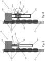
- the Figure 3 shows an alternative embodiment of the stop device 23, in which the stop wheel 231 is replaced by a stop element 237.
- the stop element 237 is designed like a pin, pencil or finger. If the supply of closures 2 to the closer 10 is to be interrupted, the stop device 23 moves the stop element 237 into the closure channel 21 by means of a corresponding trigger device 238, so that the flow of closures 2 to the closer 10 is blocked.
- the trigger device 238 can actuate the stop element 237 electrically, magnetically, hydraulically, pneumatically or purely mechanically.
- a damping device 236 is installed which, in the case of the transition from the operating state to the stop state, does not stop the shutter feed abruptly, but stops it gently along the braking path B.
- the damping device 236 can be designed as described above with respect to the Figures 2a, 2b be structured as set out.
- the Figure 4 shows a further embodiment of the stop device 23, in which a dedicated damping device 236 is dispensed with.
- the gentle braking of the shutter feed is achieved in this case by a stop wheel 231 with associated braking device 233 (cf. Figures 2a and 2b ) is installed and the braking device 233 is set up such that during the transition from the operating state to the stop state the closure feed in the closure channel 21 is braked along a braking distance greater than zero.
- the braking device 233 comprises a speed-adjustable electric motor, for example a synchronous motor, which is set up to brake the stop wheel 231 in a controlled manner over a certain angle of rotation which corresponds to the intended braking distance.
- the stop wheel 231 is mounted stationary to the locking channel 21, whereby the position can be adjusted, for example, by means of the guide 234.
- a guide 234 can also be dispensed with.
Landscapes
- Engineering & Computer Science (AREA)
- Mechanical Engineering (AREA)
- Sealing Of Jars (AREA)
Claims (14)
- Dispositif (20) pour l'alimentation de fermetures (2) à une machine de fermeture (10) pour la fermeture de récipients avec les fermetures (2), de préférence dans une installation de mise en bouteille de boissons, dans lequel le dispositif (20) présente :
une goulotte de fermeture (21) pour l'alimentation des fermetures (2) à la machine de fermeture (10), dans lequel la goulotte de fermeture (21) est disposée et conçue de telle sorte que les fermetures (2) sont guidées et transportées le long d'un chemin de transport prédéfini par la goulotte de fermeture (21) ; caractérisé en ce que le dispositif présente en outre :
un dispositif d'arrêt (23) comportant un arrêt (230) conçu pour ralentir et arrêter l'alimentation des fermetures (2) vers la machine de fermeture (10) dans la goulotte de fermeture (21) le long d'un chemin de freinage (B). - Dispositif (20) selon la revendication 1, caractérisé en ce que l'arrêt (230) comprend un élément d'arrêt (237) réalisé en forme de broche, de goupille ou de doigt, et l'arrêt (230) est conçu pour introduire l'élément d'arrêt (237) dans la goulotte de fermeture (21) de telle sorte que l'alimentation des fermetures (2) vers la machine de fermeture (10) peut être bloquée, dans lequel l'élément d'arrêt (237) est de préférence monté de manière à pouvoir être déplacé le long de la goulotte de fermeture (21).
- Dispositif (20) selon la revendication 1, caractérisé en ce que l'arrêt (230) comprend une roue d'arrêt (231) montée rotative comportant plusieurs sections de mise en prise (231a) disposées sur la circonférence, qui peuvent être mises en prise respectivement avec une fermeture (2) pour l'arrêt de l'alimentation des fermetures (2) à la machine de fermeture (10) dans la goulotte de fermeture (21).
- Dispositif (20) selon la revendication 3, caractérisé en ce que le dispositif d'arrêt (23) présente un dispositif de freinage (233) relié à la roue d'arrêt (231) et conçu pour arrêter une rotation de la roue d'arrêt (231), dans lequel le dispositif de freinage (233) comprend de préférence un moteur électrique à vitesse variable.
- Dispositif (20) selon l'une des revendications précédentes, caractérisé en ce que l'arrêt (230) est monté de manière à pouvoir être déplacé le long du chemin de freinage (B), dans lequel le dispositif d'arrêt (23) présente de préférence un guide (234) sur lequel l'arrêt (230) est installé de manière à pouvoir être déplacé.
- Dispositif (20) selon la revendication 5, caractérisé en ce que le dispositif d'arrêt (23) présente un dispositif d'amortissement (236) conçu pour amortir un déplacement de l'arrêt (230) le long du chemin de freinage (B).
- Dispositif (20) selon la revendication 6, caractérisé en ce que le dispositif d'amortissement (236) comprend une pièce élastique allongée, de préférence un ressort, qui est fixée d'un côté à un support (235) stationnaire par rapport à la goulotte de fermeture (21) et de l'autre côté à l'arrêt (230).
- Dispositif (20) selon l'une des revendications précédentes, caractérisé en ce que la goulotte de fermeture (21) est disposée et conçue de telle sorte que les fermetures (2) peuvent être transportées le long du chemin de transport sous l'effet de la gravité, dans lequel la goulotte de fermeture (21) est inclinée et/ou verticale au moins par sections.
- Dispositif (20) selon la revendication 8, caractérisé en ce que la goulotte de fermeture (21) est conçue de telle sorte qu'à une position donnée du chemin de transport se trouve toujours au maximum exactement une fermeture (2), de sorte que les fermetures (2) se déplacent dans la goulotte de fermeture (21) les unes derrière les autres le long du chemin de transport.
- Dispositif (20) selon l'une des revendications précédentes, caractérisé en ce que le chemin de freinage (B) présente une composante verticale, de préférence s'étend dans la direction de la gravité.
- Dispositif (1), de préférence dans une installation de mise en bouteille de boissons, comportant une machine de fermeture (10) pour la fermeture de récipients, un dispositif (20) qui y est relié pour l'alimentation des fermetures (2) à la machine de fermeture (10) selon l'une des revendications précédentes et un dispositif de mise à disposition (30) qui est conçu pour mettre à disposition des fermetures (2)pour la fermeture des récipients et les transférer au dispositif (20) pour l'alimentation des fermetures (2).
- Dispositif (1) selon la revendication 11, caractérisé en ce que le dispositif de mise à disposition (30) est conçu pour trier et/ou aligner les fermetures (2).
- Dispositif (1) selon la revendication 12, caractérisé en ce que le dispositif de mise à disposition (30) présente un réservoir de fermetures (31) qui est conçu pour la réception d'une pluralité de fermetures (2), dans lequel le réservoir de fermetures (31) présente de préférence un agitateur pour le mélange et/ou le transport et/ou l'orientation des fermetures (2).
- Dispositif (1) selon l'une des revendications 11 à 13, caractérisé en ce que le dispositif d'arrêt (23) est conçu pour freiner l'alimentation des fermetures (2) à la machine de fermeture (10) dans la goulotte de fermeture (21) lors du passage d'un état de fonctionnement, dans lequel les fermetures (2) doivent être alimentées à la machine de fermeture (10), à un état d'arrêt, dans lequel l'alimentation des fermetures à la machine de fermeture (10) doit être interrompue, le long du chemin de freinage (B).
Applications Claiming Priority (1)
| Application Number | Priority Date | Filing Date | Title |
|---|---|---|---|
| DE102021127329.3A DE102021127329A1 (de) | 2021-10-21 | 2021-10-21 | Vorrichtung zur Zufuhr von Verschlüssen an einen Verschließer in einer Getränkeabfüllanlage |
Publications (3)
| Publication Number | Publication Date |
|---|---|
| EP4169871A1 EP4169871A1 (fr) | 2023-04-26 |
| EP4169871C0 EP4169871C0 (fr) | 2024-08-28 |
| EP4169871B1 true EP4169871B1 (fr) | 2024-08-28 |
Family
ID=83995108
Family Applications (1)
| Application Number | Title | Priority Date | Filing Date |
|---|---|---|---|
| EP22203085.0A Active EP4169871B1 (fr) | 2021-10-21 | 2022-10-21 | Dispositif d'alimentation de bouchons à un dispositif de fermeture dans une installation de remplissage de boissons |
Country Status (3)
| Country | Link |
|---|---|
| EP (1) | EP4169871B1 (fr) |
| CN (1) | CN116002599B (fr) |
| DE (1) | DE102021127329A1 (fr) |
Family Cites Families (17)
| Publication number | Priority date | Publication date | Assignee | Title |
|---|---|---|---|---|
| IT1277135B1 (it) * | 1995-01-05 | 1997-11-04 | Mauro Lenzi | Dispositivo per l espulsione automatica da un condotto di alimentazione di capsule, tappi o elementi generalmente concavi, di |
| CN2749856Y (zh) * | 2004-12-07 | 2006-01-04 | 中国国际海运集装箱(集团)股份有限公司 | 一种输送机挡板机构 |
| DE102006039091A1 (de) * | 2006-08-19 | 2008-02-21 | Khs Ag | Vorrichtung zum Zuführen von Verschlüssen an eine Verschließmaschine |
| CN101678965B (zh) * | 2007-04-11 | 2014-08-13 | 西德尔合作公司 | 具有偏移星形轮的盖供给单元 |
| WO2009139013A1 (fr) * | 2008-05-16 | 2009-11-19 | Gea Procomac S.P.A. | Dispositif pour délivrer des fermetures de contenant |
| JP2010070248A (ja) * | 2008-09-22 | 2010-04-02 | Shibuya Kogyo Co Ltd | キャッパ |
| JP5267309B2 (ja) * | 2009-04-28 | 2013-08-21 | 澁谷工業株式会社 | キャッピング装置 |
| DE102012103518A1 (de) | 2012-04-20 | 2013-10-24 | Krones Ag | Vorrichtung zum Verschließen von Behältern |
| DE102012110102A1 (de) * | 2012-10-23 | 2014-04-24 | Krones Ag | Vorrichtung und Verfahren zum Zuführen von Verschlüssen |
| CN103130158B (zh) * | 2013-03-06 | 2015-04-01 | 长沙经济技术开发区博雅机械有限公司 | 塑料瓶盖压盖机 |
| CN203529381U (zh) * | 2013-08-30 | 2014-04-09 | 机科发展科技股份有限公司 | 带缓冲机构的输送机阻挡器 |
| CN204173889U (zh) * | 2014-09-18 | 2015-02-25 | 杭州中亚机械股份有限公司 | 一种塑盖供应装置 |
| DE102016105586B3 (de) * | 2016-03-24 | 2017-03-23 | Wörner Automatisierungstechnik GmbH | Anschlagmodul zum positionsgenauen Anhalten eines Gegenstands |
| CN108640062B (zh) * | 2018-05-11 | 2020-07-17 | 合肥中辰轻工机械有限公司 | 一种塑料盖输盖滑道用反盖退盖器 |
| DE102018129548A1 (de) | 2018-11-23 | 2020-05-28 | Krones Ag | Vorrichtung und Verfahren zum Zuführen von Verschlüssen zu einem Verschließer zum Verschließen von Behältern |
| CN214086564U (zh) * | 2020-12-18 | 2021-08-31 | 上海明略人工智能(集团)有限公司 | 用于输送设备的挡停装置、输送设备 |
| CN113086537A (zh) * | 2021-05-10 | 2021-07-09 | 广州漂移方块智能科技有限公司 | 一种柔性生产线用挡停机构及柔性生产线 |
-
2021
- 2021-10-21 DE DE102021127329.3A patent/DE102021127329A1/de active Pending
-
2022
- 2022-10-19 CN CN202211282010.XA patent/CN116002599B/zh active Active
- 2022-10-21 EP EP22203085.0A patent/EP4169871B1/fr active Active
Also Published As
| Publication number | Publication date |
|---|---|
| DE102021127329A1 (de) | 2023-04-27 |
| CN116002599B (zh) | 2026-01-23 |
| CN116002599A (zh) | 2023-04-25 |
| EP4169871C0 (fr) | 2024-08-28 |
| EP4169871A1 (fr) | 2023-04-26 |
Similar Documents
| Publication | Publication Date | Title |
|---|---|---|
| EP2444363B1 (fr) | Dispositif et procédé destinés à la fermeture de récipients avec bouchons | |
| DE102020131105A1 (de) | Vorrichtung zum linearen Transportieren von Behältern | |
| EP2222582B1 (fr) | Zone tampon d'articles | |
| DE102013110161A1 (de) | Rotierendes Behandlungskarussell | |
| EP2733096B1 (fr) | Dispositif permettant de mettre en tampon des pièces moulées dans une installation de remplissage de boissons | |
| EP2653435B1 (fr) | Dispositif destiné à fermer des récipients | |
| EP4091984A1 (fr) | Dispositif de fermeture et appareil de fermeture permettant de fermer un récipient | |
| EP2370330B1 (fr) | Système d'alimentation en récipients | |
| EP3901084A1 (fr) | Dispositif de transport linéaire des récipients | |
| DE4242163C2 (de) | Verfahren zum Behandeln von Gefäßen und Anlage zu dessen Durchführung | |
| EP2492238A1 (fr) | Dispositif destiné à fermer des récipients | |
| EP4169871A1 (fr) | Dispositif d'alimentation de bouchons à un dispositif de fermeture dans une installation de remplissage de boissons | |
| EP0353534B1 (fr) | Machine de traitement de bouteilles munies de fermeture à étrier, en particulier boucheuse en combinaison avec une étiqueteuse | |
| DE10122752B4 (de) | Antrieb für höhenverstellbare Behälterträger an Abfüllmaschinen | |
| DE1602476A1 (de) | Einrichtung zum Handhaben von Behaeltern | |
| EP2285725B1 (fr) | Dispositif pour fermer des récipients avec un bouchon à visser | |
| EP2724975B1 (fr) | Système et procédé d'alimentation de bouchons à un carrousel de bouchage | |
| WO2022089972A1 (fr) | Roue en étoile de transport pour transporter des contenants | |
| EP4008683A1 (fr) | Dispositif de manutention d'au moins un récipient | |
| EP3670432B1 (fr) | Support de récipient pour dispositif de remplissage à jet libre | |
| DE4129452A1 (de) | Verschliessmaschine | |
| EP3741722B1 (fr) | Agencement de fermeture permettant de fermer un récipient à l'aide d'une fermeture pour récipient | |
| EP4091983A1 (fr) | Installation de remplissage permettant de remplir un produit de remplissage | |
| DE102022127240A1 (de) | Behältertransportvorrichtung mit einer Führungsvorrichtung und Verfahren zum Transportieren von Behältern | |
| DD248025A3 (de) | Einrichtung zur zufuehrung von korken in die verschliessorgane einer flaschenverschliessmaschine |
Legal Events
| Date | Code | Title | Description |
|---|---|---|---|
| PUAI | Public reference made under article 153(3) epc to a published international application that has entered the european phase |
Free format text: ORIGINAL CODE: 0009012 |
|
| STAA | Information on the status of an ep patent application or granted ep patent |
Free format text: STATUS: THE APPLICATION HAS BEEN PUBLISHED |
|
| AK | Designated contracting states |
Kind code of ref document: A1 Designated state(s): AL AT BE BG CH CY CZ DE DK EE ES FI FR GB GR HR HU IE IS IT LI LT LU LV MC ME MK MT NL NO PL PT RO RS SE SI SK SM TR |
|
| STAA | Information on the status of an ep patent application or granted ep patent |
Free format text: STATUS: REQUEST FOR EXAMINATION WAS MADE |
|
| 17P | Request for examination filed |
Effective date: 20230921 |
|
| RBV | Designated contracting states (corrected) |
Designated state(s): AL AT BE BG CH CY CZ DE DK EE ES FI FR GB GR HR HU IE IS IT LI LT LU LV MC ME MK MT NL NO PL PT RO RS SE SI SK SM TR |
|
| GRAP | Despatch of communication of intention to grant a patent |
Free format text: ORIGINAL CODE: EPIDOSNIGR1 |
|
| STAA | Information on the status of an ep patent application or granted ep patent |
Free format text: STATUS: GRANT OF PATENT IS INTENDED |
|
| RIC1 | Information provided on ipc code assigned before grant |
Ipc: B67B 3/064 20060101ALI20240215BHEP Ipc: B67B 3/06 20060101AFI20240215BHEP |
|
| INTG | Intention to grant announced |
Effective date: 20240319 |
|
| GRAS | Grant fee paid |
Free format text: ORIGINAL CODE: EPIDOSNIGR3 |
|
| GRAA | (expected) grant |
Free format text: ORIGINAL CODE: 0009210 |
|
| STAA | Information on the status of an ep patent application or granted ep patent |
Free format text: STATUS: THE PATENT HAS BEEN GRANTED |
|
| AK | Designated contracting states |
Kind code of ref document: B1 Designated state(s): AL AT BE BG CH CY CZ DE DK EE ES FI FR GB GR HR HU IE IS IT LI LT LU LV MC ME MK MT NL NO PL PT RO RS SE SI SK SM TR |
|
| REG | Reference to a national code |
Ref country code: CH Ref legal event code: EP |
|
| REG | Reference to a national code |
Ref country code: DE Ref legal event code: R096 Ref document number: 502022001569 Country of ref document: DE |
|
| REG | Reference to a national code |
Ref country code: IE Ref legal event code: FG4D Free format text: LANGUAGE OF EP DOCUMENT: GERMAN |
|
| U01 | Request for unitary effect filed |
Effective date: 20240904 |
|
| U07 | Unitary effect registered |
Designated state(s): AT BE BG DE DK EE FI FR IT LT LU LV MT NL PT RO SE SI Effective date: 20240923 |
|
| U20 | Renewal fee for the european patent with unitary effect paid |
Year of fee payment: 3 Effective date: 20240925 |
|
| PG25 | Lapsed in a contracting state [announced via postgrant information from national office to epo] |
Ref country code: NO Free format text: LAPSE BECAUSE OF FAILURE TO SUBMIT A TRANSLATION OF THE DESCRIPTION OR TO PAY THE FEE WITHIN THE PRESCRIBED TIME-LIMIT Effective date: 20241128 |
|
| PG25 | Lapsed in a contracting state [announced via postgrant information from national office to epo] |
Ref country code: GR Free format text: LAPSE BECAUSE OF FAILURE TO SUBMIT A TRANSLATION OF THE DESCRIPTION OR TO PAY THE FEE WITHIN THE PRESCRIBED TIME-LIMIT Effective date: 20241129 Ref country code: PL Free format text: LAPSE BECAUSE OF FAILURE TO SUBMIT A TRANSLATION OF THE DESCRIPTION OR TO PAY THE FEE WITHIN THE PRESCRIBED TIME-LIMIT Effective date: 20240828 |
|
| PG25 | Lapsed in a contracting state [announced via postgrant information from national office to epo] |
Ref country code: IS Free format text: LAPSE BECAUSE OF FAILURE TO SUBMIT A TRANSLATION OF THE DESCRIPTION OR TO PAY THE FEE WITHIN THE PRESCRIBED TIME-LIMIT Effective date: 20241228 |
|
| PG25 | Lapsed in a contracting state [announced via postgrant information from national office to epo] |
Ref country code: HR Free format text: LAPSE BECAUSE OF FAILURE TO SUBMIT A TRANSLATION OF THE DESCRIPTION OR TO PAY THE FEE WITHIN THE PRESCRIBED TIME-LIMIT Effective date: 20240828 |
|
| PG25 | Lapsed in a contracting state [announced via postgrant information from national office to epo] |
Ref country code: RS Free format text: LAPSE BECAUSE OF FAILURE TO SUBMIT A TRANSLATION OF THE DESCRIPTION OR TO PAY THE FEE WITHIN THE PRESCRIBED TIME-LIMIT Effective date: 20241128 Ref country code: ES Free format text: LAPSE BECAUSE OF FAILURE TO SUBMIT A TRANSLATION OF THE DESCRIPTION OR TO PAY THE FEE WITHIN THE PRESCRIBED TIME-LIMIT Effective date: 20240828 |
|
| PG25 | Lapsed in a contracting state [announced via postgrant information from national office to epo] |
Ref country code: RS Free format text: LAPSE BECAUSE OF FAILURE TO SUBMIT A TRANSLATION OF THE DESCRIPTION OR TO PAY THE FEE WITHIN THE PRESCRIBED TIME-LIMIT Effective date: 20241128 Ref country code: PL Free format text: LAPSE BECAUSE OF FAILURE TO SUBMIT A TRANSLATION OF THE DESCRIPTION OR TO PAY THE FEE WITHIN THE PRESCRIBED TIME-LIMIT Effective date: 20240828 Ref country code: NO Free format text: LAPSE BECAUSE OF FAILURE TO SUBMIT A TRANSLATION OF THE DESCRIPTION OR TO PAY THE FEE WITHIN THE PRESCRIBED TIME-LIMIT Effective date: 20241128 Ref country code: IS Free format text: LAPSE BECAUSE OF FAILURE TO SUBMIT A TRANSLATION OF THE DESCRIPTION OR TO PAY THE FEE WITHIN THE PRESCRIBED TIME-LIMIT Effective date: 20241228 Ref country code: HR Free format text: LAPSE BECAUSE OF FAILURE TO SUBMIT A TRANSLATION OF THE DESCRIPTION OR TO PAY THE FEE WITHIN THE PRESCRIBED TIME-LIMIT Effective date: 20240828 Ref country code: GR Free format text: LAPSE BECAUSE OF FAILURE TO SUBMIT A TRANSLATION OF THE DESCRIPTION OR TO PAY THE FEE WITHIN THE PRESCRIBED TIME-LIMIT Effective date: 20241129 Ref country code: ES Free format text: LAPSE BECAUSE OF FAILURE TO SUBMIT A TRANSLATION OF THE DESCRIPTION OR TO PAY THE FEE WITHIN THE PRESCRIBED TIME-LIMIT Effective date: 20240828 |
|
| U1N | Appointed representative for the unitary patent procedure changed after the registration of the unitary effect |
Representative=s name: NORDMEYER, PHILIPP WERNER; DE |
|
| PG25 | Lapsed in a contracting state [announced via postgrant information from national office to epo] |
Ref country code: SM Free format text: LAPSE BECAUSE OF FAILURE TO SUBMIT A TRANSLATION OF THE DESCRIPTION OR TO PAY THE FEE WITHIN THE PRESCRIBED TIME-LIMIT Effective date: 20240828 |
|
| PG25 | Lapsed in a contracting state [announced via postgrant information from national office to epo] |
Ref country code: CZ Free format text: LAPSE BECAUSE OF FAILURE TO SUBMIT A TRANSLATION OF THE DESCRIPTION OR TO PAY THE FEE WITHIN THE PRESCRIBED TIME-LIMIT Effective date: 20240828 |
|
| PG25 | Lapsed in a contracting state [announced via postgrant information from national office to epo] |
Ref country code: SK Free format text: LAPSE BECAUSE OF FAILURE TO SUBMIT A TRANSLATION OF THE DESCRIPTION OR TO PAY THE FEE WITHIN THE PRESCRIBED TIME-LIMIT Effective date: 20240828 |
|
| PLBE | No opposition filed within time limit |
Free format text: ORIGINAL CODE: 0009261 |
|
| STAA | Information on the status of an ep patent application or granted ep patent |
Free format text: STATUS: NO OPPOSITION FILED WITHIN TIME LIMIT |
|
| PG25 | Lapsed in a contracting state [announced via postgrant information from national office to epo] |
Ref country code: MC Free format text: LAPSE BECAUSE OF FAILURE TO SUBMIT A TRANSLATION OF THE DESCRIPTION OR TO PAY THE FEE WITHIN THE PRESCRIBED TIME-LIMIT Effective date: 20240828 |
|
| 26N | No opposition filed |
Effective date: 20250530 |
|
| U20 | Renewal fee for the european patent with unitary effect paid |
Year of fee payment: 4 Effective date: 20250909 |
|
| PG25 | Lapsed in a contracting state [announced via postgrant information from national office to epo] |
Ref country code: IE Free format text: LAPSE BECAUSE OF NON-PAYMENT OF DUE FEES Effective date: 20241021 |
|
| PG25 | Lapsed in a contracting state [announced via postgrant information from national office to epo] |
Ref country code: CY Free format text: LAPSE BECAUSE OF FAILURE TO SUBMIT A TRANSLATION OF THE DESCRIPTION OR TO PAY THE FEE WITHIN THE PRESCRIBED TIME-LIMIT; INVALID AB INITIO Effective date: 20221021 |
|
| PG25 | Lapsed in a contracting state [announced via postgrant information from national office to epo] |
Ref country code: HU Free format text: LAPSE BECAUSE OF FAILURE TO SUBMIT A TRANSLATION OF THE DESCRIPTION OR TO PAY THE FEE WITHIN THE PRESCRIBED TIME-LIMIT; INVALID AB INITIO Effective date: 20221021 |