EP3670438B1 - Gelenk ausserhalb der ebene für mikro- und nanoelektromechanische systeme mit reduzierter nichtlinearität - Google Patents
Gelenk ausserhalb der ebene für mikro- und nanoelektromechanische systeme mit reduzierter nichtlinearität Download PDFInfo
- Publication number
- EP3670438B1 EP3670438B1 EP19215918.4A EP19215918A EP3670438B1 EP 3670438 B1 EP3670438 B1 EP 3670438B1 EP 19215918 A EP19215918 A EP 19215918A EP 3670438 B1 EP3670438 B1 EP 3670438B1
- Authority
- EP
- European Patent Office
- Prior art keywords
- plane
- parts
- blades
- deform
- several
- Prior art date
- Legal status (The legal status is an assumption and is not a legal conclusion. Google has not performed a legal analysis and makes no representation as to the accuracy of the status listed.)
- Active
Links
Images



Classifications
-
- E—FIXED CONSTRUCTIONS
- E05—LOCKS; KEYS; WINDOW OR DOOR FITTINGS; SAFES
- E05D—HINGES OR SUSPENSION DEVICES FOR DOORS, WINDOWS OR WINGS
- E05D3/00—Hinges with pins
- E05D3/06—Hinges with pins with two or more pins
-
- F—MECHANICAL ENGINEERING; LIGHTING; HEATING; WEAPONS; BLASTING
- F16—ENGINEERING ELEMENTS AND UNITS; GENERAL MEASURES FOR PRODUCING AND MAINTAINING EFFECTIVE FUNCTIONING OF MACHINES OR INSTALLATIONS; THERMAL INSULATION IN GENERAL
- F16C—SHAFTS; FLEXIBLE SHAFTS; ELEMENTS OR CRANKSHAFT MECHANISMS; ROTARY BODIES OTHER THAN GEARING ELEMENTS; BEARINGS
- F16C11/00—Pivots; Pivotal connections
- F16C11/04—Pivotal connections
-
- B—PERFORMING OPERATIONS; TRANSPORTING
- B81—MICROSTRUCTURAL TECHNOLOGY
- B81B—MICROSTRUCTURAL DEVICES OR SYSTEMS, e.g. MICROMECHANICAL DEVICES
- B81B7/00—Microstructural systems ; Auxiliary parts of microstructural devices or systems
- B81B7/0003—MEMS mechanisms for assembling automatically hinged components, self-assembly devices
-
- F—MECHANICAL ENGINEERING; LIGHTING; HEATING; WEAPONS; BLASTING
- F16—ENGINEERING ELEMENTS AND UNITS; GENERAL MEASURES FOR PRODUCING AND MAINTAINING EFFECTIVE FUNCTIONING OF MACHINES OR INSTALLATIONS; THERMAL INSULATION IN GENERAL
- F16C—SHAFTS; FLEXIBLE SHAFTS; ELEMENTS OR CRANKSHAFT MECHANISMS; ROTARY BODIES OTHER THAN GEARING ELEMENTS; BEARINGS
- F16C11/00—Pivots; Pivotal connections
- F16C11/04—Pivotal connections
- F16C11/12—Pivotal connections incorporating flexible connections, e.g. leaf springs
-
- G—PHYSICS
- G01—MEASURING; TESTING
- G01C—MEASURING DISTANCES, LEVELS OR BEARINGS; SURVEYING; NAVIGATION; GYROSCOPIC INSTRUMENTS; PHOTOGRAMMETRY OR VIDEOGRAMMETRY
- G01C19/00—Gyroscopes; Turn-sensitive devices using vibrating masses; Turn-sensitive devices without moving masses; Measuring angular rate using gyroscopic effects
- G01C19/56—Turn-sensitive devices using vibrating masses, e.g. vibratory angular rate sensors based on Coriolis forces
-
- G—PHYSICS
- G01—MEASURING; TESTING
- G01P—MEASURING LINEAR OR ANGULAR SPEED, ACCELERATION, DECELERATION, OR SHOCK; INDICATING PRESENCE, ABSENCE, OR DIRECTION, OF MOVEMENT
- G01P15/00—Measuring acceleration; Measuring deceleration; Measuring shock, i.e. sudden change of acceleration
- G01P15/02—Measuring acceleration; Measuring deceleration; Measuring shock, i.e. sudden change of acceleration by making use of inertia forces using solid seismic masses
- G01P15/08—Measuring acceleration; Measuring deceleration; Measuring shock, i.e. sudden change of acceleration by making use of inertia forces using solid seismic masses with conversion into electric or magnetic values
-
- B—PERFORMING OPERATIONS; TRANSPORTING
- B81—MICROSTRUCTURAL TECHNOLOGY
- B81B—MICROSTRUCTURAL DEVICES OR SYSTEMS, e.g. MICROMECHANICAL DEVICES
- B81B2201/00—Specific applications of microelectromechanical systems
- B81B2201/02—Sensors
- B81B2201/0228—Inertial sensors
- B81B2201/0235—Accelerometers
-
- B—PERFORMING OPERATIONS; TRANSPORTING
- B81—MICROSTRUCTURAL TECHNOLOGY
- B81B—MICROSTRUCTURAL DEVICES OR SYSTEMS, e.g. MICROMECHANICAL DEVICES
- B81B2201/00—Specific applications of microelectromechanical systems
- B81B2201/02—Sensors
- B81B2201/0257—Microphones or microspeakers
-
- B—PERFORMING OPERATIONS; TRANSPORTING
- B81—MICROSTRUCTURAL TECHNOLOGY
- B81B—MICROSTRUCTURAL DEVICES OR SYSTEMS, e.g. MICROMECHANICAL DEVICES
- B81B2203/00—Basic microelectromechanical structures
- B81B2203/01—Suspended structures, i.e. structures allowing a movement
- B81B2203/0109—Bridges
-
- B—PERFORMING OPERATIONS; TRANSPORTING
- B81—MICROSTRUCTURAL TECHNOLOGY
- B81B—MICROSTRUCTURAL DEVICES OR SYSTEMS, e.g. MICROMECHANICAL DEVICES
- B81B2203/00—Basic microelectromechanical structures
- B81B2203/01—Suspended structures, i.e. structures allowing a movement
- B81B2203/0145—Flexible holders
- B81B2203/0154—Torsion bars
-
- B—PERFORMING OPERATIONS; TRANSPORTING
- B81—MICROSTRUCTURAL TECHNOLOGY
- B81B—MICROSTRUCTURAL DEVICES OR SYSTEMS, e.g. MICROMECHANICAL DEVICES
- B81B2203/00—Basic microelectromechanical structures
- B81B2203/01—Suspended structures, i.e. structures allowing a movement
- B81B2203/0145—Flexible holders
- B81B2203/0163—Spring holders
-
- B—PERFORMING OPERATIONS; TRANSPORTING
- B81—MICROSTRUCTURAL TECHNOLOGY
- B81B—MICROSTRUCTURAL DEVICES OR SYSTEMS, e.g. MICROMECHANICAL DEVICES
- B81B2203/00—Basic microelectromechanical structures
- B81B2203/05—Type of movement
- B81B2203/053—Translation according to an axis perpendicular to the substrate
-
- B—PERFORMING OPERATIONS; TRANSPORTING
- B81—MICROSTRUCTURAL TECHNOLOGY
- B81B—MICROSTRUCTURAL DEVICES OR SYSTEMS, e.g. MICROMECHANICAL DEVICES
- B81B3/00—Devices comprising flexible or deformable elements, e.g. comprising elastic tongues or membranes
- B81B3/0035—Constitution or structural means for controlling the movement of the flexible or deformable elements
- B81B3/0037—For increasing stroke, i.e. achieve large displacement of actuated parts
-
- G—PHYSICS
- G01—MEASURING; TESTING
- G01P—MEASURING LINEAR OR ANGULAR SPEED, ACCELERATION, DECELERATION, OR SHOCK; INDICATING PRESENCE, ABSENCE, OR DIRECTION, OF MOVEMENT
- G01P15/00—Measuring acceleration; Measuring deceleration; Measuring shock, i.e. sudden change of acceleration
- G01P15/02—Measuring acceleration; Measuring deceleration; Measuring shock, i.e. sudden change of acceleration by making use of inertia forces using solid seismic masses
- G01P15/08—Measuring acceleration; Measuring deceleration; Measuring shock, i.e. sudden change of acceleration by making use of inertia forces using solid seismic masses with conversion into electric or magnetic values
- G01P2015/0805—Measuring acceleration; Measuring deceleration; Measuring shock, i.e. sudden change of acceleration by making use of inertia forces using solid seismic masses with conversion into electric or magnetic values being provided with a particular type of spring-mass-system for defining the displacement of a seismic mass due to an external acceleration
- G01P2015/0822—Measuring acceleration; Measuring deceleration; Measuring shock, i.e. sudden change of acceleration by making use of inertia forces using solid seismic masses with conversion into electric or magnetic values being provided with a particular type of spring-mass-system for defining the displacement of a seismic mass due to an external acceleration for defining out-of-plane movement of the mass
- G01P2015/084—Measuring acceleration; Measuring deceleration; Measuring shock, i.e. sudden change of acceleration by making use of inertia forces using solid seismic masses with conversion into electric or magnetic values being provided with a particular type of spring-mass-system for defining the displacement of a seismic mass due to an external acceleration for defining out-of-plane movement of the mass the mass being suspended at more than one of its sides, e.g. membrane-type suspension, so as to permit multi-axis movement of the mass
-
- H—ELECTRICITY
- H04—ELECTRIC COMMUNICATION TECHNIQUE
- H04R—LOUDSPEAKERS, MICROPHONES, GRAMOPHONE PICK-UPS OR LIKE ACOUSTIC ELECTROMECHANICAL TRANSDUCERS; ELECTRIC HEARING AIDS; PUBLIC ADDRESS SYSTEMS
- H04R19/00—Electrostatic transducers
- H04R19/005—Electrostatic transducers using semiconductor materials
Definitions
- the present invention relates to an out-of-plane joint for microelectromechanical and/or nanoelectromechanical systems offering reduced non-linearity and to a system implementing at least two such joints.
- Microelectromechanical systems or MEMS microelectromechanical systems in English terminology
- micro and nanoelectromechanical systems or M&NEMS systems micro & nanoelectromechanical systems in English terminology
- MEMS microelectromechanical systems in English terminology
- M&NEMS systems micro & nanoelectromechanical systems in English terminology
- MEMS microelectromechanical systems in English terminology
- M&NEMS systems micro & nanoelectromechanical systems in English terminology
- the mobile element is suspended relative to the substrate and depending on the applications, it may be desired that it has a displacement in the plane of the system or an out-of-plane displacement, i.e. orthogonal to the plane of the system.
- connection zone may exhibit significant non-linearity.
- the mobile mass M is suspended from the substrate S by an articulation A formed by a thin membrane.
- the displacement in the Z direction of the mass M causes a deformation of the membrane at the first order in the Z direction and at the second order in the X direction.
- the elongation of the membrane in the X direction ( figure 1B ) is no longer negligible.
- the restoring force exerted by the membrane on the mass is nonlinear ( figure 1C ) and varies significantly with movement in the Z direction. This non-linearity can significantly affect the response of the system, for example in the case of a sensor, and can make it unreliable.
- the document US 2015/033860 A1 of the prior art describes an articulation between at least a first element and at least a second element of a microelectromechanical system, said first element and said second element being movable relative to each other at least in one direction outside -plan, said articulation comprising a second part intended to be anchored on the first element, said second part being configured to deform in bending in a first direction, and two third parts intended to be anchored on the second element, the third parts being configured to deform in bending along a second direction orthogonal to the first direction.
- a hinge intended to connect a first element and a second element of a MEMS or M&NEMS system, comprising a first part which is rigid in the three directions in space, a second part connected to the first part and intended to be connected to the first element, the second part being thin and intended to extend in the plane of the system, and able to be deformed in bending in the out-of-plane direction, and two third parts configured to deform in in-plane bending, the two third parts being each connected to one end of the first part so that when there is relative movement between the first and the second member in the first direction, the first part deforms in bending in the out-of-plane direction and the two third parts deform in bending in a direction of the plane.
- the third parts then offer an elongation in the plane making it possible to limit the deformation of the first part in the plane, and therefore reduces the non-linearity of the articulation.
- the deformation in the plane of the first part is reduced, even avoided by the slight bending of the third parts which accompany the first part in its movement in the plane.
- a composite joint comprising several parts which each provide a function and which makes it possible to reduce the non-linearity of the joint.
- the articulation combines both an articulation obtained by an element stressed in bending in the out-of-plane direction and an articulation obtained by elements configured to deform in flexion according to a direction in the plane, which makes it possible to offer the possibility of a large amplitude displacement in the out-of-plane direction while maintaining a low degree of non-linearity.
- each part can be designed to adapt the properties of the joint according to the needs, for example the flexibility can be varied in the out-of-plane direction and/or the guidance can be improved in a given direction.
- a MEMS or M&NEMS system comprises at least two joints, which ensures very good guidance in the out-of-plane direction and at least guidance in one direction in the plane.
- the MEMS or M&NEMS system comprises at least three joints, and even more advantageously four joints, making it possible to provide guidance in the out-of-plane direction and very good support in the two directions of the plane.
- the present invention therefore relates to a joint between at least a first element and at least a second element of a microelectromechanical system, said first element and said second element being movable relative to each other at least in one direction.
- said articulation comprising a first rigid part, a second part secured to the first part by one end and intended to be anchored to the first element, said second part being configured to be deformable in bending in a first direction, and two third parts integral with the first part and intended to be anchored to the second element, the third parts being configured to deform in bending along a second direction orthogonal to the first direction.
- the third parts in an undeformed state, extend in a plane orthogonal to a plane in which the second part extends.
- the second part has a dimension in the first direction that is reduced compared to the dimensions in the other directions.
- the first part extends, in the first direction, between a first plane and a second plane and the second part comprises a face located in one of the first and second planes.
- the third parts comprise at least two blades, extending over at least part of the dimension of the first part in the first direction, for example over the entire dimension of the first part in the first direction.
- each third part comprises a blade, the two blades being coplanar and being arranged so as to also deform in torsion. The joint is then more flexible in the out-of-plane direction.
- each third part comprises two blades, one blade of each third part being coplanar with a blade of the other third part and the two blades of a third part are arranged relative to one another so as to do not or little deform in torsion.
- the blades make it possible to obtain the linearity of the articulation with little or no modification of the out-of-plane stiffness of the articulation.
- the second parts can advantageously comprise a lattice structure so as to ensure flexibility in the first direction and a certain rigidity in at least one third direction orthogonal to the first and second directions.
- the second part has a thickness in the first direction comprised between a hundred nm and a few microns, a length in the third direction and a width in the second direction comprised between a few ⁇ m and a few hundred ⁇ m.
- the third parts have a thickness in the first direction comprised between 10 ⁇ m and a few tens of ⁇ m, a width in the second direction of the plane comprised between 100 nm and a few micrometers and a length in the third direction comprised between a few ⁇ m and a few tens of ⁇ m.
- the first part has a thickness in the first direction, a length in the third direction and a width in the second direction comprised between a few ⁇ m and a few hundred ⁇ m.
- the present invention also relates to a microelectromechanical system comprising a first element and at least one second element movable relative to each other at least in an out-of-plane direction, and at least two joints according to the invention, each anchored to the first element and the second element, and the joints are oriented so that the first direction is the out-of-plane direction and the second and third directions are the in-plane directions.
- the at least two joints are arranged symmetrically with respect to a plane of symmetry of the movable part, said median plane containing the out-of-plane direction.
- the second plane is on the side of the fixed part and the second part comprises a face extending in the second plane.
- the system may include at least four joints so that the axes of the torsion of the third parts of the joints are arranged orthogonally with respect to each other.
- the microelectromechanical system comprises means for setting the second element in motion at least in an out-of-plane direction.
- the microelectromechanical system is for example a microphone.
- microelectromechanical system or “MEMS system” denotes a micro and/or nanoelectromechanical system, i.e. comprising elements having micrometric dimensions and/or elements having nanometric dimensions.
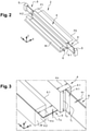
- a joint 2 according to the invention.
- a fixed part or substrate S of a microelectromechanical system and a mobile part or mass M intended to be suspended from the substrate S by the articulation 2.
- the articulation can realize the articulation between two movable parts between them, and themselves movable with respect to a fixed substrate.
- the articulation 2 is intended to allow an out-of-plane movement of the mobile part M.
- the system plane is defined by the X and Y directions and corresponds to the mean plane of the system in which the mobile mass M extends, it is also the mean plane of the fixed part.
- the Z out-of-plane direction is orthogonal to the system plane.
- the joint comprises a first rigid part 4.
- rigid part or element means an element which deforms little or not at all under the effect of the stresses generally applied to a MEMS system in the case of a sensor or an actuator in normal operation.
- the first part 4 has the shape of a parallelepipedic beam having a thickness Tb, a width Wb and a length Lb.
- the first part extends in the Z direction between a first parallel plane P1 and a second plane P2.
- the thickness Tb corresponds to the dimension of the beam along the Z direction
- the width Wb corresponds to the dimension of the beam along the X direction
- the length Lb corresponds to the dimension of the beam along the Y direction.
- Tb, Wb and Lb are for example between a few ⁇ m and a few hundred ⁇ m.
- the joint 2 comprises a second part 6 having a low thickness Tm compared to its length Lm and its width Wm so as to allow its bending deformation in the direction Z.
- the ratios Tm/Wm and Tm/Lm are for example between 1/100 and 1/10.
- its thickness Tm is between a hundred nm and a few hundred nm
- its length Lm and its width Wm are between a few ⁇ m and a few hundred ⁇ m.
- the second part 6 then has the shape of a membrane which is secured to the first part 4 by a first edge 6.1 extending in the direction Y, and by a second edge 6.2 parallel to the first edge 6.1 and intended to be secured to the mass M.
- the membrane is arranged in the example shown on the plane P2 delimiting the lower face of the first part in the example shown. Furthermore, in the example represented the lower face of the mass M is also contained in the plane P2.
- the membrane could be anchored to the mobile part in any position between the planes P1 and P2.
- Joint 2 comprises two third parts 8 forming blades and secured by an edge 8.1 to one end of beam 4.1, 4.2 along direction Y.
- the blades extend in plane YZ.
- the blades are sized to be able to deform in bending in the X direction.
- the blades have a thickness TI of between 10 ⁇ m and a few tens of ⁇ m, a width Wl of between 100 nm and a few micrometers and a length LI of between a few ⁇ m and a few tens of ⁇ m.
- the blades 8 extend in a median plane R of the beam parallel to the plane YZ.
- the blades 8 are intended to be anchored on the fixed part S by an edge 8.2 parallel to the edge 8.1.
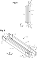
- a MEMS system 10 implementing two joints 2.
- the joints 2 are anchored on the movable part M symmetrically with respect to a plane of symmetry of the movable part M parallel to the plane YZ.
- the membranes 6 are anchored on parallel faces M.1, M.2 of the mobile part M.
- the blades are anchored on the fixed part S.
- the mobile part M has an upwards out-of-plane movement, the membranes are deformed in bending and the blades 8 are deformed in bending in the direction X.
- the two blades 8 will also deform in torsion around the Y axis, which makes it possible to lower the stiffness of the joint.
- a sensor for example an accelerometer intended to measure the acceleration in the Z direction.
- the bending deformations of the blades 8 along X allows the beams 4 to move in the direction X, and the edges of the beams 4, to which the edges 6.1 of the membranes are fixed, to accompany the membranes 6 in their deformation along the direction X
- the membranes are mainly deformed in the Z direction and are no longer stretched along X. Thanks to the invention, the joints retain a low degree of non-linearity even for displacements along Z of high amplitude.
- the moving part is guided along the Z direction.
- the joints 2 have great rigidity in the Y direction, the movable part is therefore very well maintained in the Y direction. In addition, the joints 2 also ensure that the movable part M is held in the X direction.
- the system comprises four joints 2 arranged at 90° to each other.
- Each joint 2 is anchored on an edge of the mobile mass M".
- the systems configurations of the figures 8 and 9 provide very good support for the moving parts M in the XY plane and their guidance in the Z direction.
- the articulation comprises a pair of blades 8' at each end of the beam 4.
- the blades 8' of each pair are positioned parallel to each other in the YZ plane. In this example, one of their faces is aligned with a face of the beam parallel to the YZ plane.
- the implementation of two blades 8 'parallel at each end makes it possible to block the torsional deformation of each of the blades.
- the two blades 8' of each pair individually tend to deform in torsion, but in combination each blade 8' prevents the torsion deformation of the other blade 8' during the out-of-plane movement of the movable part M.
- the blades then deform mainly in bending and accompany the displacement of the membrane 6 in the plane. The non-linear stiffness of the joint is noticeably reduced.
- the membranes are structured to have shapes providing great flexibility along Z and great stiffness in the plane, for example they include braces or lattices and/or are perforated.
- the rigidity of the joint in the different directions is determined both by the dimensions of the membrane and the dimensions of the blades, so it is possible to finely adjust these rigidities by acting on the dimensions of the membrane and /or on the dimensions of the blades.
- the rigidity of the joints is increased, it is also possible to control the displacement of the mass in the Z direction.
- the articulation has the advantage of offering very good guidance along Z while being relatively compact due to its small thickness.
- the joints can be configured to allow a desired movement in the direction X.
- the blades can be lengthened in the direction of the beam and/or made thinner, providing some flexibility in the X direction.
- the operation is similar to that of the system of the figure 5 . Very good holding in the Y direction and guidance in the Z direction are obtained with a low degree of non-linearity.
- FIG. 7 another example of a MEMS system with four joints can be seen. Two joints 102 are anchored to a first edge M.1 of the mobile mass M and two joints 102 are anchored to a second edge M.2 of the mobile mass M parallel to the first edge.
- the length Lb of the first part 104 is small compared to the length Lm of the blades 108.
- the membranes 104 have a large width Lm compared to their length Lm.
- the mobile part M can be seen in the rest state, and in an out-of-plane position during movement.
- the displacement in the Z direction is of the order of 40 nm.
- Such a structure allows a displacement of between approximately 100 nm and approximately 1 ⁇ m.
- the joints of figure 5 and 6 can be combined, for example the structure comprises a movable part suspended by two joints according to the invention, one is secured to the movable part by its second part ( figure 5 ) and the other is secured to its movable part by its third parts.
- the articulation according to the invention can be implemented in MEMS sensors for this means for detecting the movement of the mass along Z are provided, for example capacitive means or piezoresistive or piezoelectric strain gauges.
- the joint according to the invention can be implemented in MEMS actuators, for this means 12 for actuating the movable part in the Z direction are provided, for example electrostatic means represented schematically on the figure 7 .
- the electrostatic means comprise at least one pair of electrodes, one being formed on the substrate under the mobile part M and the other electrode being formed on the mobile part M facing the electrode on the substrate S. application of a potential difference generates electrostatic forces between the two electrodes and therefore an out-of-plane displacement of the mobile mass M with respect to the substrate S.
- a MEMS system comprising joints according to the invention can be used to produce a microphone.
- the moving part M can form a piston that can move in Z under the effect of a pressure differential between its two faces, due to a sound wave
- the articulation and the MEMS system can advantageously be manufactured by known methods of microelectronics by deposition of layers and etchings.
- the examples of manufacturing process described in the document FR2941533 can be implemented to achieve such a MEMS system.
- the membranes are formed by the upper layer of a silicon on insulator substrate or SOI (Silicon on Insulator in Anglo-Saxon terminology) and the first part and the blades are made by etching and releasing.
- the membranes are made by depositing a layer with a thickness of a few hundred nm and the first part and the blades are made by etching and releasing.
- At least the first part and the third parts are made in the same layer in which the mobile part and part of the fixed part are made.
- the system is for example made of semiconductor material, such as silicon or SiGe.
Landscapes
- Engineering & Computer Science (AREA)
- Physics & Mathematics (AREA)
- General Physics & Mathematics (AREA)
- General Engineering & Computer Science (AREA)
- Mechanical Engineering (AREA)
- Computer Hardware Design (AREA)
- Microelectronics & Electronic Packaging (AREA)
- Radar, Positioning & Navigation (AREA)
- Remote Sensing (AREA)
- Micromachines (AREA)
Claims (15)
- Gelenk zwischen wenigstens einem ersten Element (S) und wenigstens einem zweiten Element (M) eines mikroelektromechanischen Systems, wobei das erste Element (S) und das zweite Element (M) wenigstens in einer Richtung außerhalb der Ebene relativ zueinander beweglich sind, wobei das Gelenk einen ersten starren Teil (4) und einen zweiten Teil (6) umfasst, der mit einem Ende fest mit dem ersten Teil (4) verbunden ist und dazu bestimmt ist, an dem ersten Element verankert zu werden, wobei der zweite Teil (6) derart ausgebildet ist, dass er durch Biegung in einer ersten Richtung (Z) verformbar ist, und zwei dritte Teile (8), die fest mit dem ersten Teil (4) verbunden sind und dazu bestimmt sind, an dem zweiten Element (M) verankert zu werden, wobei die dritten Teile (8) dazu ausgebildet sind, sich entlang einer zweiten Richtung (X) orthogonal zu der ersten Richtung (Z) durch Biegung zu verformen.
- Gelenk nach Anspruch 1, wobei sich die dritten Teile (8) in einem nicht verformten Zustand in einer Ebene erstrecken, die orthogonal zu einer Ebene ist, in der sich der zweite Teil (6) erstreckt.
- Gelenk nach Anspruch 1 oder 2, wobei der zweite Teil (6) in der ersten Richtung (Z) eine gegenüber den Abmessungen in den anderen Richtungen reduzierte Abmessung aufweist.
- Gelenk nach Anspruch 1, 2 oder 3, wobei sich der erste Teil (4) in der ersten Richtung (Z) zwischen einer ersten Ebene (P1) und einer zweiten Ebene (P2) erstreckt und wobei der zweite Teil (6) eine Fläche aufweist, die in der ersten Ebene (P1) oder der zweiten Ebene (P2) liegt.
- Gelenk nach einem der Ansprüche 1-4, wobei die dritten Teile (8) wenigstens zwei Lamellen umfassen, die sich über wenigstens einen Teil der Abmessung des ersten Teils (4) in der ersten Richtung (Z) erstrecken.
- Gelenk nach Anspruch 5, wobei jeder dritte Teil eine Lamelle umfasst, wobei die Lamelle des einen dritten Teils und die Lamelle des anderen dritten Teils koplanar sind und dazu angeordnet sind, sich ebenfalls durch Torsion zu verformen, oder wobei jeder dritte Teil zwei Lamellen umfasst, wobei eine Lamelle jedes dritten Teils koplanar mit einer Lamelle des anderen dritten Teils ist und wobei die beiden Lamellen eines dritten Teils relativ zueinander derart angeordnet sind, dass sie eine geringe oder keine Verformung durch Torsion aufzuweisen.
- Gelenk nach einem der Ansprüche 1 bis 6, wobei die beiden Teile (6) eine Gitterstruktur aufweisen, um eine Flexibilität in der ersten Richtung (Z) und eine gewisse Steifigkeit in wenigstens einer dritten Richtung (Y) orthogonal zur ersten (Z) und zweiten (X) Richtung zu gewährleisten.
- Gelenk nach einem der vorhergehenden Ansprüche, wobei der zweite Teil (6) eine Dicke (Tm) in der ersten Richtung (Z) zwischen hundert nm und einigen Mikron, eine Länge (Lm) in der dritten Richtung (Y) und eine Breite (Wm) in der zweiten Richtung (X) zwischen einigen µm und einigen hundert µm aufweist.
- Gelenk nach einem der vorhergehenden Ansprüche, wobei die dritten Teile (8) eine Dicke (TI) in der ersten Richtung (Z) zwischen 10 µm und einigen Dutzend µm, eine Breite (WI) in der zweiten Richtung (X) der Ebene zwischen 100 nm und einigen Mikrometern und eine Länge (LI) in der dritten Richtung (Y) zwischen einigen µm und einigen Dutzend µm aufweisen.
- Gelenk nach einem der vorhergehenden Ansprüche, wobei der erste Teil eine Dicke (Tb) in der ersten Richtung (Z), eine Länge (Lb) in der dritten Richtung (Y) und eine Breite (Wb) in der zweiten Richtung (X) zwischen einigen µm und einigen hundert µm aufweist.
- Mikroelektromechanisches System, umfassend wenigstens ein erstes Element (S) und wenigstens ein zweites Element (M), die wenigstens in einer Richtung außerhalb der Ebene relativ zueinander beweglich sind, und wenigstens zwei Gelenke nach einem der Ansprüche 1 bis 10, die jeweils an dem ersten Element (S) und dem zweiten Element (M) verankert sind, und wobei die Gelenke derart ausgerichtet sind, dass die erste Richtung die Richtung außerhalb der Ebene ist und die zweite und dritte Richtung die Richtungen innerhalb der Ebene sind, wobei die wenigstens zwei Gelenke vorteilhafterweise symmetrisch in Bezug auf eine Symmetrieebene des beweglichen Teils (M) angeordnet sind, wobei die Mittelebene die Richtung außerhalb der Ebene enthält.
- Mikroelektromechanisches System nach Anspruch 11 in Verbindung mit Anspruch 4, wobei die zweite Ebene (P2) auf der Seite des festen Teils (S) liegt und der zweite Teil (6) eine Fläche aufweist, die sich in der zweiten Ebene (P2) erstreckt.
- Mikroelektromechanisches System nach Anspruch 11, 12 oder 13, umfassend wenigstens vier Gelenke, so dass die Torsionsachsen der dritten Teile der Gelenke orthogonal zueinander angeordnet sind.
- Mikroelektromechanisches System nach einem der Ansprüche 11 bis 13, umfassend Mittel (12), um das zweite Element (M) wenigstens in einer Richtung außerhalb der Ebene in Bewegung zu setzen.
- Mikroelektromechanisches System nach einem der Ansprüche 11 bis 14, welches ein Mikrofon bildet.
Applications Claiming Priority (1)
| Application Number | Priority Date | Filing Date | Title |
|---|---|---|---|
| FR1873564A FR3090612B1 (fr) | 2018-12-20 | 2018-12-20 | Articulation hors-plan pour systemes micro et nanoelectromecaniques a non-linearite reduite |
Publications (2)
| Publication Number | Publication Date |
|---|---|
| EP3670438A1 EP3670438A1 (de) | 2020-06-24 |
| EP3670438B1 true EP3670438B1 (de) | 2022-03-23 |
Family
ID=66530287
Family Applications (1)
| Application Number | Title | Priority Date | Filing Date |
|---|---|---|---|
| EP19215918.4A Active EP3670438B1 (de) | 2018-12-20 | 2019-12-13 | Gelenk ausserhalb der ebene für mikro- und nanoelektromechanische systeme mit reduzierter nichtlinearität |
Country Status (5)
| Country | Link |
|---|---|
| US (1) | US11674344B2 (de) |
| EP (1) | EP3670438B1 (de) |
| CN (1) | CN111350752B (de) |
| ES (1) | ES2914412T3 (de) |
| FR (1) | FR3090612B1 (de) |
Family Cites Families (10)
| Publication number | Priority date | Publication date | Assignee | Title |
|---|---|---|---|---|
| FR2808264B1 (fr) * | 2000-04-28 | 2002-06-07 | Commissariat Energie Atomique | Structure mecanique micro-usinee et dispositif incorporant la structure |
| US20070199805A1 (en) * | 2004-03-29 | 2007-08-30 | Pioneer Corporation | Hinge Structure and Hinge Structure Member |
| FR2941533B1 (fr) | 2009-01-23 | 2011-03-11 | Commissariat Energie Atomique | Capteur inertiel ou resonnant en technologie de surface, a detection hors plan par jauge de contrainte. |
| FR2951826B1 (fr) * | 2009-10-23 | 2012-06-15 | Commissariat Energie Atomique | Capteur a detection piezoresistive dans le plan |
| JPWO2011161943A1 (ja) * | 2010-06-24 | 2013-08-19 | パナソニック株式会社 | 光学反射素子 |
| FR2983844B1 (fr) * | 2011-12-12 | 2014-08-08 | Commissariat Energie Atomique | Liaison mecanique formant pivot pour structures mecaniques mems et nems |
| CN104379949B (zh) * | 2012-05-18 | 2016-10-12 | 独立行政法人产业技术综合研究所 | 回转轴保持机构及使用该机构的回转粘度计 |
| JP6159426B2 (ja) * | 2013-03-14 | 2017-07-05 | ラヴィヴ エルリク | 高度の回転性を有するmemsヒンジ |
| DE102013208824B4 (de) * | 2013-05-14 | 2025-10-02 | Robert Bosch Gmbh | Beschleunigungssensor |
| KR101531093B1 (ko) * | 2013-07-31 | 2015-06-23 | 삼성전기주식회사 | 가속도 센서 및 각속도 센서 |
-
2018
- 2018-12-20 FR FR1873564A patent/FR3090612B1/fr not_active Expired - Fee Related
-
2019
- 2019-12-13 ES ES19215918T patent/ES2914412T3/es active Active
- 2019-12-13 EP EP19215918.4A patent/EP3670438B1/de active Active
- 2019-12-17 US US16/716,632 patent/US11674344B2/en active Active
- 2019-12-19 CN CN201911319376.8A patent/CN111350752B/zh active Active
Also Published As
| Publication number | Publication date |
|---|---|
| FR3090612A1 (fr) | 2020-06-26 |
| CN111350752A (zh) | 2020-06-30 |
| FR3090612B1 (fr) | 2021-01-22 |
| ES2914412T3 (es) | 2022-06-10 |
| US20200199923A1 (en) | 2020-06-25 |
| EP3670438A1 (de) | 2020-06-24 |
| CN111350752B (zh) | 2024-05-03 |
| US11674344B2 (en) | 2023-06-13 |
Similar Documents
| Publication | Publication Date | Title |
|---|---|---|
| EP2791048B1 (de) | Mechanische verbindung zur formung einer gelenkvorrichtung für mechanische mems- und nems- strukturen | |
| EP3766829B1 (de) | Mechanische verbindung für mems- und nems-vorrichtungen zum messen einer druckveränderung und vorrichtung, die eine solche mechanische verbindung umfasst | |
| EP2938569B1 (de) | Mikroelektromechanische vorrichtung mit einer in drei dimensionen beweglichen masse | |
| EP3599469B1 (de) | Beschleunigungssensor mit dehnungsmessstreifen mit verbesserter präzision | |
| EP3070963B1 (de) | Mems und/oder nems drucksensor mit verbesserten leistungen und dynamisches mikrofon mit einem solchen sensor. | |
| EP2309559A1 (de) | Piezoelektrische Erregerstruktur mit integriertem piezoresistivem Dehnmessstreifen und Herstellungsverfahren dafür | |
| EP3234536A2 (de) | Dynamischer drucksensor mit verbessertem betrieb | |
| EP1736435A1 (de) | Elektrostatischer Aktuator mit einem leitendem und hängendem Schwenkteil | |
| EP3670439B1 (de) | Gelenk für mikro- und nanoelektrische systeme mit bewegungen ausserhalb der ebene, das eine reduzierte nichtlinearität ermöglicht | |
| EP3722254B1 (de) | Scharnier, das eine reduzierte empfindlichkeit gegenüber innenspannungen bietet | |
| EP3670438B1 (de) | Gelenk ausserhalb der ebene für mikro- und nanoelektromechanische systeme mit reduzierter nichtlinearität | |
| EP3722253B1 (de) | Scharnier ausserhalb der ebene für mikro- und/oder nanomechanische struktur mit einer reduzierten empfindlichkeit gegenüber innenspannungen | |
| EP3498661B1 (de) | Mikro- und/oder nanoelektromechanische vorrichtung, die eine erhöhte robustheit bietet | |
| EP3828943B1 (de) | Mechanisches microsystem mit entsprechendem herstellungsprozess | |
| EP3415464B1 (de) | Mikroelektromechanische vorrichtung mit mindestens einem beweglichen element mit seitlicher bewegungsführung | |
| EP3671873B1 (de) | Elektromechanisches mikrosystem, das ein aktives element mit einer strukturierten kernschicht umfasst | |
| FR3058409A1 (fr) | Dispositif microelectromecanique et/ou nanoelectromecanique articule a deplacement hors-plan | |
| EP4155702A1 (de) | Hochempfindlicher resonanzkraftsensor mit einem prüfkörper und mindestens einem resonanzelement, die entkoppelt und jeweils in einer angepassten umgebung angeordnet sind | |
| EP4399532A1 (de) | Kraftsensor mit erweitertem betriebsbereich | |
| FR3143256A1 (fr) | Elément actif piézoélectrique pour système électromécanique | |
| FR2792068A1 (fr) | Dispositif de mesure d'une force |
Legal Events
| Date | Code | Title | Description |
|---|---|---|---|
| PUAI | Public reference made under article 153(3) epc to a published international application that has entered the european phase |
Free format text: ORIGINAL CODE: 0009012 |
|
| STAA | Information on the status of an ep patent application or granted ep patent |
Free format text: STATUS: REQUEST FOR EXAMINATION WAS MADE |
|
| 17P | Request for examination filed |
Effective date: 20191213 |
|
| AK | Designated contracting states |
Kind code of ref document: A1 Designated state(s): AL AT BE BG CH CY CZ DE DK EE ES FI FR GB GR HR HU IE IS IT LI LT LU LV MC MK MT NL NO PL PT RO RS SE SI SK SM TR |
|
| AX | Request for extension of the european patent |
Extension state: BA ME |
|
| GRAP | Despatch of communication of intention to grant a patent |
Free format text: ORIGINAL CODE: EPIDOSNIGR1 |
|
| STAA | Information on the status of an ep patent application or granted ep patent |
Free format text: STATUS: GRANT OF PATENT IS INTENDED |
|
| INTG | Intention to grant announced |
Effective date: 20210412 |
|
| GRAJ | Information related to disapproval of communication of intention to grant by the applicant or resumption of examination proceedings by the epo deleted |
Free format text: ORIGINAL CODE: EPIDOSDIGR1 |
|
| STAA | Information on the status of an ep patent application or granted ep patent |
Free format text: STATUS: REQUEST FOR EXAMINATION WAS MADE |
|
| INTC | Intention to grant announced (deleted) | ||
| GRAP | Despatch of communication of intention to grant a patent |
Free format text: ORIGINAL CODE: EPIDOSNIGR1 |
|
| STAA | Information on the status of an ep patent application or granted ep patent |
Free format text: STATUS: GRANT OF PATENT IS INTENDED |
|
| INTG | Intention to grant announced |
Effective date: 20211015 |
|
| GRAS | Grant fee paid |
Free format text: ORIGINAL CODE: EPIDOSNIGR3 |
|
| GRAA | (expected) grant |
Free format text: ORIGINAL CODE: 0009210 |
|
| STAA | Information on the status of an ep patent application or granted ep patent |
Free format text: STATUS: THE PATENT HAS BEEN GRANTED |
|
| AK | Designated contracting states |
Kind code of ref document: B1 Designated state(s): AL AT BE BG CH CY CZ DE DK EE ES FI FR GB GR HR HU IE IS IT LI LT LU LV MC MK MT NL NO PL PT RO RS SE SI SK SM TR |
|
| REG | Reference to a national code |
Ref country code: GB Ref legal event code: FG4D Free format text: NOT ENGLISH |
|
| REG | Reference to a national code |
Ref country code: CH Ref legal event code: EP |
|
| REG | Reference to a national code |
Ref country code: DE Ref legal event code: R096 Ref document number: 602019012793 Country of ref document: DE |
|
| REG | Reference to a national code |
Ref country code: IE Ref legal event code: FG4D Free format text: LANGUAGE OF EP DOCUMENT: FRENCH |
|
| REG | Reference to a national code |
Ref country code: AT Ref legal event code: REF Ref document number: 1477323 Country of ref document: AT Kind code of ref document: T Effective date: 20220415 |
|
| REG | Reference to a national code |
Ref country code: NL Ref legal event code: FP |
|
| REG | Reference to a national code |
Ref country code: ES Ref legal event code: FG2A Ref document number: 2914412 Country of ref document: ES Kind code of ref document: T3 Effective date: 20220610 |
|
| REG | Reference to a national code |
Ref country code: LT Ref legal event code: MG9D |
|
| PG25 | Lapsed in a contracting state [announced via postgrant information from national office to epo] |
Ref country code: SE Free format text: LAPSE BECAUSE OF FAILURE TO SUBMIT A TRANSLATION OF THE DESCRIPTION OR TO PAY THE FEE WITHIN THE PRESCRIBED TIME-LIMIT Effective date: 20220323 Ref country code: RS Free format text: LAPSE BECAUSE OF FAILURE TO SUBMIT A TRANSLATION OF THE DESCRIPTION OR TO PAY THE FEE WITHIN THE PRESCRIBED TIME-LIMIT Effective date: 20220323 Ref country code: NO Free format text: LAPSE BECAUSE OF FAILURE TO SUBMIT A TRANSLATION OF THE DESCRIPTION OR TO PAY THE FEE WITHIN THE PRESCRIBED TIME-LIMIT Effective date: 20220623 Ref country code: LT Free format text: LAPSE BECAUSE OF FAILURE TO SUBMIT A TRANSLATION OF THE DESCRIPTION OR TO PAY THE FEE WITHIN THE PRESCRIBED TIME-LIMIT Effective date: 20220323 Ref country code: HR Free format text: LAPSE BECAUSE OF FAILURE TO SUBMIT A TRANSLATION OF THE DESCRIPTION OR TO PAY THE FEE WITHIN THE PRESCRIBED TIME-LIMIT Effective date: 20220323 Ref country code: BG Free format text: LAPSE BECAUSE OF FAILURE TO SUBMIT A TRANSLATION OF THE DESCRIPTION OR TO PAY THE FEE WITHIN THE PRESCRIBED TIME-LIMIT Effective date: 20220623 |
|
| REG | Reference to a national code |
Ref country code: AT Ref legal event code: MK05 Ref document number: 1477323 Country of ref document: AT Kind code of ref document: T Effective date: 20220323 |
|
| PG25 | Lapsed in a contracting state [announced via postgrant information from national office to epo] |
Ref country code: LV Free format text: LAPSE BECAUSE OF FAILURE TO SUBMIT A TRANSLATION OF THE DESCRIPTION OR TO PAY THE FEE WITHIN THE PRESCRIBED TIME-LIMIT Effective date: 20220323 Ref country code: GR Free format text: LAPSE BECAUSE OF FAILURE TO SUBMIT A TRANSLATION OF THE DESCRIPTION OR TO PAY THE FEE WITHIN THE PRESCRIBED TIME-LIMIT Effective date: 20220624 Ref country code: FI Free format text: LAPSE BECAUSE OF FAILURE TO SUBMIT A TRANSLATION OF THE DESCRIPTION OR TO PAY THE FEE WITHIN THE PRESCRIBED TIME-LIMIT Effective date: 20220323 |
|
| PG25 | Lapsed in a contracting state [announced via postgrant information from national office to epo] |
Ref country code: SM Free format text: LAPSE BECAUSE OF FAILURE TO SUBMIT A TRANSLATION OF THE DESCRIPTION OR TO PAY THE FEE WITHIN THE PRESCRIBED TIME-LIMIT Effective date: 20220323 Ref country code: SK Free format text: LAPSE BECAUSE OF FAILURE TO SUBMIT A TRANSLATION OF THE DESCRIPTION OR TO PAY THE FEE WITHIN THE PRESCRIBED TIME-LIMIT Effective date: 20220323 Ref country code: RO Free format text: LAPSE BECAUSE OF FAILURE TO SUBMIT A TRANSLATION OF THE DESCRIPTION OR TO PAY THE FEE WITHIN THE PRESCRIBED TIME-LIMIT Effective date: 20220323 Ref country code: PT Free format text: LAPSE BECAUSE OF FAILURE TO SUBMIT A TRANSLATION OF THE DESCRIPTION OR TO PAY THE FEE WITHIN THE PRESCRIBED TIME-LIMIT Effective date: 20220725 Ref country code: EE Free format text: LAPSE BECAUSE OF FAILURE TO SUBMIT A TRANSLATION OF THE DESCRIPTION OR TO PAY THE FEE WITHIN THE PRESCRIBED TIME-LIMIT Effective date: 20220323 Ref country code: CZ Free format text: LAPSE BECAUSE OF FAILURE TO SUBMIT A TRANSLATION OF THE DESCRIPTION OR TO PAY THE FEE WITHIN THE PRESCRIBED TIME-LIMIT Effective date: 20220323 Ref country code: AT Free format text: LAPSE BECAUSE OF FAILURE TO SUBMIT A TRANSLATION OF THE DESCRIPTION OR TO PAY THE FEE WITHIN THE PRESCRIBED TIME-LIMIT Effective date: 20220323 |
|
| PG25 | Lapsed in a contracting state [announced via postgrant information from national office to epo] |
Ref country code: PL Free format text: LAPSE BECAUSE OF FAILURE TO SUBMIT A TRANSLATION OF THE DESCRIPTION OR TO PAY THE FEE WITHIN THE PRESCRIBED TIME-LIMIT Effective date: 20220323 Ref country code: IS Free format text: LAPSE BECAUSE OF FAILURE TO SUBMIT A TRANSLATION OF THE DESCRIPTION OR TO PAY THE FEE WITHIN THE PRESCRIBED TIME-LIMIT Effective date: 20220723 Ref country code: AL Free format text: LAPSE BECAUSE OF FAILURE TO SUBMIT A TRANSLATION OF THE DESCRIPTION OR TO PAY THE FEE WITHIN THE PRESCRIBED TIME-LIMIT Effective date: 20220323 |
|
| REG | Reference to a national code |
Ref country code: DE Ref legal event code: R097 Ref document number: 602019012793 Country of ref document: DE |
|
| PLBE | No opposition filed within time limit |
Free format text: ORIGINAL CODE: 0009261 |
|
| STAA | Information on the status of an ep patent application or granted ep patent |
Free format text: STATUS: NO OPPOSITION FILED WITHIN TIME LIMIT |
|
| PG25 | Lapsed in a contracting state [announced via postgrant information from national office to epo] |
Ref country code: DK Free format text: LAPSE BECAUSE OF FAILURE TO SUBMIT A TRANSLATION OF THE DESCRIPTION OR TO PAY THE FEE WITHIN THE PRESCRIBED TIME-LIMIT Effective date: 20220323 |
|
| 26N | No opposition filed |
Effective date: 20230102 |
|
| PG25 | Lapsed in a contracting state [announced via postgrant information from national office to epo] |
Ref country code: SI Free format text: LAPSE BECAUSE OF FAILURE TO SUBMIT A TRANSLATION OF THE DESCRIPTION OR TO PAY THE FEE WITHIN THE PRESCRIBED TIME-LIMIT Effective date: 20220323 |
|
| P01 | Opt-out of the competence of the unified patent court (upc) registered |
Effective date: 20230518 |
|
| PG25 | Lapsed in a contracting state [announced via postgrant information from national office to epo] |
Ref country code: LU Free format text: LAPSE BECAUSE OF NON-PAYMENT OF DUE FEES Effective date: 20221213 |
|
| PG25 | Lapsed in a contracting state [announced via postgrant information from national office to epo] |
Ref country code: IE Free format text: LAPSE BECAUSE OF NON-PAYMENT OF DUE FEES Effective date: 20221213 |
|
| PG25 | Lapsed in a contracting state [announced via postgrant information from national office to epo] |
Ref country code: HU Free format text: LAPSE BECAUSE OF FAILURE TO SUBMIT A TRANSLATION OF THE DESCRIPTION OR TO PAY THE FEE WITHIN THE PRESCRIBED TIME-LIMIT; INVALID AB INITIO Effective date: 20191213 |
|
| PG25 | Lapsed in a contracting state [announced via postgrant information from national office to epo] |
Ref country code: CY Free format text: LAPSE BECAUSE OF FAILURE TO SUBMIT A TRANSLATION OF THE DESCRIPTION OR TO PAY THE FEE WITHIN THE PRESCRIBED TIME-LIMIT Effective date: 20220323 |
|
| PG25 | Lapsed in a contracting state [announced via postgrant information from national office to epo] |
Ref country code: MK Free format text: LAPSE BECAUSE OF FAILURE TO SUBMIT A TRANSLATION OF THE DESCRIPTION OR TO PAY THE FEE WITHIN THE PRESCRIBED TIME-LIMIT Effective date: 20220323 |
|
| PG25 | Lapsed in a contracting state [announced via postgrant information from national office to epo] |
Ref country code: MC Free format text: LAPSE BECAUSE OF FAILURE TO SUBMIT A TRANSLATION OF THE DESCRIPTION OR TO PAY THE FEE WITHIN THE PRESCRIBED TIME-LIMIT Effective date: 20220323 |
|
| PG25 | Lapsed in a contracting state [announced via postgrant information from national office to epo] |
Ref country code: MC Free format text: LAPSE BECAUSE OF FAILURE TO SUBMIT A TRANSLATION OF THE DESCRIPTION OR TO PAY THE FEE WITHIN THE PRESCRIBED TIME-LIMIT Effective date: 20220323 |
|
| PG25 | Lapsed in a contracting state [announced via postgrant information from national office to epo] |
Ref country code: MT Free format text: LAPSE BECAUSE OF FAILURE TO SUBMIT A TRANSLATION OF THE DESCRIPTION OR TO PAY THE FEE WITHIN THE PRESCRIBED TIME-LIMIT Effective date: 20220323 |
|
| PG25 | Lapsed in a contracting state [announced via postgrant information from national office to epo] |
Ref country code: TR Free format text: LAPSE BECAUSE OF FAILURE TO SUBMIT A TRANSLATION OF THE DESCRIPTION OR TO PAY THE FEE WITHIN THE PRESCRIBED TIME-LIMIT Effective date: 20220323 |
|
| REG | Reference to a national code |
Ref country code: CH Ref legal event code: U11 Free format text: ST27 STATUS EVENT CODE: U-0-0-U10-U11 (AS PROVIDED BY THE NATIONAL OFFICE) Effective date: 20260101 |
|
| PGFP | Annual fee paid to national office [announced via postgrant information from national office to epo] |
Ref country code: GB Payment date: 20251229 Year of fee payment: 7 |
|
| PGFP | Annual fee paid to national office [announced via postgrant information from national office to epo] |
Ref country code: NL Payment date: 20251223 Year of fee payment: 7 Ref country code: FR Payment date: 20251222 Year of fee payment: 7 |
|
| PGFP | Annual fee paid to national office [announced via postgrant information from national office to epo] |
Ref country code: BE Payment date: 20251224 Year of fee payment: 7 |
|
| PGFP | Annual fee paid to national office [announced via postgrant information from national office to epo] |
Ref country code: ES Payment date: 20260119 Year of fee payment: 7 |
|
| PGFP | Annual fee paid to national office [announced via postgrant information from national office to epo] |
Ref country code: DE Payment date: 20251222 Year of fee payment: 7 |
|
| PGFP | Annual fee paid to national office [announced via postgrant information from national office to epo] |
Ref country code: IT Payment date: 20251231 Year of fee payment: 7 |
|
| PGFP | Annual fee paid to national office [announced via postgrant information from national office to epo] |
Ref country code: CH Payment date: 20260101 Year of fee payment: 7 |