EP3670439B1 - Gelenk für mikro- und nanoelektrische systeme mit bewegungen ausserhalb der ebene, das eine reduzierte nichtlinearität ermöglicht - Google Patents
Gelenk für mikro- und nanoelektrische systeme mit bewegungen ausserhalb der ebene, das eine reduzierte nichtlinearität ermöglicht Download PDFInfo
- Publication number
- EP3670439B1 EP3670439B1 EP19217628.7A EP19217628A EP3670439B1 EP 3670439 B1 EP3670439 B1 EP 3670439B1 EP 19217628 A EP19217628 A EP 19217628A EP 3670439 B1 EP3670439 B1 EP 3670439B1
- Authority
- EP
- European Patent Office
- Prior art keywords
- plane
- parts
- hinge
- joint
- dimensions
- Prior art date
- Legal status (The legal status is an assumption and is not a legal conclusion. Google has not performed a legal analysis and makes no representation as to the accuracy of the status listed.)
- Active
Links
Images



Classifications
-
- G—PHYSICS
- G02—OPTICS
- G02B—OPTICAL ELEMENTS, SYSTEMS OR APPARATUS
- G02B6/00—Light guides; Structural details of arrangements comprising light guides and other optical elements, e.g. couplings
- G02B6/24—Coupling light guides
- G02B6/26—Optical coupling means
- G02B6/35—Optical coupling means having switching means
- G02B6/351—Optical coupling means having switching means involving stationary waveguides with moving interposed optical elements
- G02B6/3512—Optical coupling means having switching means involving stationary waveguides with moving interposed optical elements the optical element being reflective, e.g. mirror
- G02B6/3518—Optical coupling means having switching means involving stationary waveguides with moving interposed optical elements the optical element being reflective, e.g. mirror the reflective optical element being an intrinsic part of a MEMS device, i.e. fabricated together with the MEMS device
-
- B—PERFORMING OPERATIONS; TRANSPORTING
- B81—MICROSTRUCTURAL TECHNOLOGY
- B81B—MICROSTRUCTURAL DEVICES OR SYSTEMS, e.g. MICROMECHANICAL DEVICES
- B81B3/00—Devices comprising flexible or deformable elements, e.g. comprising elastic tongues or membranes
- B81B3/0035—Constitution or structural means for controlling the movement of the flexible or deformable elements
- B81B3/004—Angular deflection
- B81B3/0048—Constitution or structural means for controlling angular deflection not provided for in groups B81B3/0043 - B81B3/0045
-
- G—PHYSICS
- G01—MEASURING; TESTING
- G01P—MEASURING LINEAR OR ANGULAR SPEED, ACCELERATION, DECELERATION, OR SHOCK; INDICATING PRESENCE, ABSENCE, OR DIRECTION, OF MOVEMENT
- G01P15/00—Measuring acceleration; Measuring deceleration; Measuring shock, i.e. sudden change of acceleration
- G01P15/02—Measuring acceleration; Measuring deceleration; Measuring shock, i.e. sudden change of acceleration by making use of inertia forces using solid seismic masses
- G01P15/08—Measuring acceleration; Measuring deceleration; Measuring shock, i.e. sudden change of acceleration by making use of inertia forces using solid seismic masses with conversion into electric or magnetic values
- G01P15/125—Measuring acceleration; Measuring deceleration; Measuring shock, i.e. sudden change of acceleration by making use of inertia forces using solid seismic masses with conversion into electric or magnetic values by capacitive pick-up
-
- G—PHYSICS
- G01—MEASURING; TESTING
- G01P—MEASURING LINEAR OR ANGULAR SPEED, ACCELERATION, DECELERATION, OR SHOCK; INDICATING PRESENCE, ABSENCE, OR DIRECTION, OF MOVEMENT
- G01P15/00—Measuring acceleration; Measuring deceleration; Measuring shock, i.e. sudden change of acceleration
- G01P15/18—Measuring acceleration; Measuring deceleration; Measuring shock, i.e. sudden change of acceleration in two or more dimensions
-
- G—PHYSICS
- G02—OPTICS
- G02B—OPTICAL ELEMENTS, SYSTEMS OR APPARATUS
- G02B26/00—Optical devices or arrangements for the control of light using movable or deformable optical elements
- G02B26/08—Optical devices or arrangements for the control of light using movable or deformable optical elements for controlling the direction of light
- G02B26/0816—Optical devices or arrangements for the control of light using movable or deformable optical elements for controlling the direction of light by means of one or more reflecting elements
- G02B26/0833—Optical devices or arrangements for the control of light using movable or deformable optical elements for controlling the direction of light by means of one or more reflecting elements the reflecting element being a micromechanical device, e.g. a MEMS mirror, DMD
- G02B26/085—Optical devices or arrangements for the control of light using movable or deformable optical elements for controlling the direction of light by means of one or more reflecting elements the reflecting element being a micromechanical device, e.g. a MEMS mirror, DMD the reflecting means being moved or deformed by electromagnetic means
-
- G—PHYSICS
- G02—OPTICS
- G02B—OPTICAL ELEMENTS, SYSTEMS OR APPARATUS
- G02B27/00—Optical systems or apparatus not provided for by any of the groups G02B1/00 - G02B26/00, G02B30/00
- G02B27/56—Optics using evanescent waves, i.e. inhomogeneous waves
-
- H—ELECTRICITY
- H04—ELECTRIC COMMUNICATION TECHNIQUE
- H04R—LOUDSPEAKERS, MICROPHONES, GRAMOPHONE PICK-UPS OR LIKE ACOUSTIC ELECTROMECHANICAL TRANSDUCERS; ELECTRIC HEARING AIDS; PUBLIC ADDRESS SYSTEMS
- H04R19/00—Electrostatic transducers
- H04R19/04—Microphones
-
- B—PERFORMING OPERATIONS; TRANSPORTING
- B81—MICROSTRUCTURAL TECHNOLOGY
- B81B—MICROSTRUCTURAL DEVICES OR SYSTEMS, e.g. MICROMECHANICAL DEVICES
- B81B2203/00—Basic microelectromechanical structures
- B81B2203/01—Suspended structures, i.e. structures allowing a movement
- B81B2203/0109—Bridges
-
- B—PERFORMING OPERATIONS; TRANSPORTING
- B81—MICROSTRUCTURAL TECHNOLOGY
- B81B—MICROSTRUCTURAL DEVICES OR SYSTEMS, e.g. MICROMECHANICAL DEVICES
- B81B2203/00—Basic microelectromechanical structures
- B81B2203/01—Suspended structures, i.e. structures allowing a movement
- B81B2203/0145—Flexible holders
- B81B2203/0163—Spring holders
-
- B—PERFORMING OPERATIONS; TRANSPORTING
- B81—MICROSTRUCTURAL TECHNOLOGY
- B81B—MICROSTRUCTURAL DEVICES OR SYSTEMS, e.g. MICROMECHANICAL DEVICES
- B81B2203/00—Basic microelectromechanical structures
- B81B2203/05—Type of movement
- B81B2203/053—Translation according to an axis perpendicular to the substrate
-
- H—ELECTRICITY
- H04—ELECTRIC COMMUNICATION TECHNIQUE
- H04R—LOUDSPEAKERS, MICROPHONES, GRAMOPHONE PICK-UPS OR LIKE ACOUSTIC ELECTROMECHANICAL TRANSDUCERS; ELECTRIC HEARING AIDS; PUBLIC ADDRESS SYSTEMS
- H04R19/00—Electrostatic transducers
- H04R19/005—Electrostatic transducers using semiconductor materials
Definitions
- the present invention relates to a joint for micro and nanoelectromechanical systems offering at least reduced non-linearity and to a system implementing at least two such joints.
- Microelectromechanical systems or MEMS microelectromechanical systems in English terminology
- micro and nanoelectromechanical systems or M&NEMS systems micro & nanoelectromechanical systems in English terminology
- MEMS microelectromechanical systems in English terminology
- M&NEMS systems micro & nanoelectromechanical systems in English terminology
- MEMS microelectromechanical systems in English terminology
- M&NEMS systems micro & nanoelectromechanical systems in English terminology
- the mobile element is suspended relative to the substrate and depending on the applications, it may be desired that it has a displacement in the plane of the system or an out-of-plane displacement, i.e. orthogonal to the plane of the system.
- connection zone may exhibit significant non-linearity.
- the mobile mass M is suspended from the substrate S by an articulation A formed by a thin membrane.
- the displacement in the Z direction of the mass M causes a deformation of the membrane at the first order in the Z direction and at the second order in the X direction.
- the elongation of the membrane in the X direction ( figure 12B ) is no longer negligible.
- the restoring force exerted by the membrane on the mass is nonlinear ( figure 12C ) and varies significantly with movement in the Z direction. This non-linearity can significantly affect the response of the system, for example in the case of a sensor, and can make it unreliable.
- the document WO 01/98786 describes an accelerometer comprising a mass connected to a support by U-shaped elastic beams connected to the mass and to the support by the free ends of the branches of the U.
- a joint intended to connect a first element and a second element of a MEMS or M&NEMS system, comprising a first part which is rigid in the three directions of the space, at least a second part connected to the first part and intended to be connected to the first element, the second part being able to be deformed in bending in the out-of-plane direction, and at least a third part connected to the first part and able to be deformed in bending in the out-of-plane direction, the second and the third parts extending at rest on the same plane.
- the second and third parts are arranged with respect to the first part and to the two elements of the system so that, during the relative displacement of the first element and the second element in the out-of-plane direction, the second part and the third part each undergo a deformation in the plane, the amplitudes of the deformations of the second and third parts in the plane are at least close and at least partially compensate each other.
- the deformations in the plane of the second and third parts are identical and fully compensate each other.
- the articulation undergoes little, or even no deformation in the plane at the level of the attachments to the first and second element, and therefore has little or no non-linearity, and this even during large amplitude out-of-plane displacements.
- the deformations in the plane of the joint are at least partly compensated.
- an articulation is produced which self-cancels at least in part the deformations in the plane responsible for non-linear behavior.
- the invention does not limit the in-plane deformation, but compensates for it at least in part by means of a composite joint.
- the joint according to the invention also has the advantage of making it possible to easily adjust its rigidity by choosing the dimensions of the second and third parts.
- the second and third parts are membranes and have the same dimensions, thus exhibiting the same mechanical behavior when they are deformed in bending.
- an M&NEMS system comprises at least two joints which ensures very good guidance in the out-of-plane direction and at least guidance in one direction in the plane.
- the M&NEMS system comprises at least three joints, and even more advantageously four joints, making it possible to provide guidance in the out-of-plane direction and very good support in the two directions of the plane.
- the present invention also relates to a microelectromechanical system comprising a first element and a second element movable with respect to one another in an out-of-plane direction, and at least two joints according to the invention, each anchored to the first element and to the second element , and the joints are oriented so that the first direction is the out-of-plane direction and the second and third directions are the in-plane directions.
- microelectromechanical system or “MEMS system” denotes a micro and/or nanoelectromechanical system, i.e. comprising elements having micrometric dimensions and/or elements having nanometric dimensions.
- a joint 2 according to the invention.
- a fixed part or substrate S of a microelectromechanical system and a mobile part or mass M intended to be suspended from the substrate S by the articulation 2.
- the articulation can achieve the articulation between two movable parts between them, and themselves movable relative to a fixed substrate.
- the articulation 2 is intended to allow an out-of-plane movement of the mobile part M.
- the system plane is defined by the X and Y directions and corresponds to the mean plane of the system in which the mobile mass M extends, it is also the mean plane of the fixed part.
- the Z out-of-plane direction is orthogonal to the system plane.
- the joint comprises a first rigid part 4.
- rigid part or element means an element which deforms little or not at all under the effect of the stresses generally applied to a MEMS system in the case of a sensor or an actuator in normal operation.
- the first part 4 has the shape of a parallelepipedal beam having a thickness Tb, a width Wb and a length Lb.
- the first part extends in the Z direction between a first plane P1 and a second plane P2 parallel to each other.
- the thickness corresponds to the dimension along Z
- the width corresponds to the dimension along X
- the length corresponds to the dimension along Y.
- Tb, Wb and Lb are for example between a few ⁇ m and a few hundred ⁇ m.
- the joint comprises a second part 6 having a low thickness Tm compared to its length Lm and its width Wm, so as to allow its bending deformation in the direction Z, preferably 1/10 ⁇ Tm/Wm ⁇ 1/ 100 and 1/10 ⁇ Tm/Lm ⁇ 1/100.
- its thickness Tm is between a hundred nm and a few ⁇ m
- its length Lm and its width Wm are between a few ⁇ m and a few hundred ⁇ m.
- the second part 6 then has the shape of a membrane which is secured by a first edge 6.1 extending in the direction Y to a first side 4.1 of the first part 4, and a second edge 6.2 parallel to the first edge 6.1 and intended to be secured to the mass M.
- the second part 6 connects the first part 4 and the mass M.
- the lower face of the second part is arranged at rest on the plane P2 in which the lower face of the first part 4 is located in the representation of the figures 1 to 4 .
- the lower face of the mass M is also contained in the plane P2.
- the articulation also comprises a third part 8 having a thickness Tm' which is small compared to its length Lm' and to its width Wm' so as to allow its deformation in bending in the direction Z, preferably 1/10 ⁇ Tm'/Wm' ⁇ 1/100 and 1/10 ⁇ Tm'/Lm' ⁇ 1/100.
- the second part 6 and the third part 8 are configured so as to present similar or identical mechanical behaviors, during an out-of-plane displacement of the mobile part M with respect to the substrate S.
- the dimensions are equal to the inaccuracies related to the manufacturing process.
- the third part 8 then also has the form of a membrane which is secured by a first edge 8.1 extending in the direction Y to the first edge 4.1 of the first part 4, and a second edge 8.2 parallel to the first edge 8.1 and intended to be attached to the substrate S.
- the second 6 and third 8 parts are connected to the same side of the first part 4 and are arranged next to each other.
- the lower face of the third part 8 is also disposed at rest on the plane P2 delimiting the lower face of the first part 4 in the representation of the figures 1 to 4 .
- the lower faces of the second part 6 and the third part 8 are at rest located on the same plane P2 orthogonal to the out-of-plane direction.
- a MEMS system 10 implementing two joints 2.
- the joints 2 are anchored on the movable part M symmetrically with respect to a median plane of the movable part M parallel to the plane YZ.
- the second parts of each joint are anchored on parallel faces M.1, M.2 of the mobile part M, and the third parts are anchored on the fixed part S.
- the movable part M has an upward out-of-plane movement, the second parts and third parts are deformed in bending.
- a sensor for example an accelerometer intended to measure the acceleration in the Z direction.
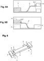
- the second parts 6 are deformed between the first part 4 and the mass ( figure 5A ), their end connected to the mass undergoes a deformation ⁇ x1 in the XY plane in the X direction.
- the third parts 8 are deformed between the first part 4 and the substrate S ( figure 5B ), their end connected to the first part undergoes a deformation ⁇ x2 in the XY plane in the X direction.
- the dimensions and materials of the second and third parts are determined so that the amplitude of the deformation ⁇ x1 is close to or equal to the amplitude of the deformation ⁇ x2
- the amplitude of the deformation ⁇ x1 is equal to the amplitude of the deformation ⁇ x2, they completely compensate each other.
- the joint then presents a pure and linear out-of-plane stiffness.
- joint 102 in which the joint comprises two third parts 108 arranged on either side of the second part 106.
- the two third parts 108 have the same length Lm" and this is equal to half the length Lm of the second part 106 and the other dimensions Wm" and Tm" of the two third ones are identical to those Wm and Tm of the second part 106.
- the two third parts of width Lm " 2 Lm are mechanically equivalent to a single third part of width Lm and therefore undergoing the same deformation in the plane ⁇ x2.
- the equivalent Y-direction dimension of the second part(s) is equal to the equivalent Y-direction dimension of the third part(s).
- “Equivalent dimension” of the second part or of the third part in the Y direction is understood to mean the dimension of the second part or of the third part in the Y direction or the sum of the dimensions of the second parts or of the dimensions of the third parts in the Y direction.
- the articulation comprises two second parts on either side of a third part.
- the articulation comprises m second parts and n third parts, with m and n being strictly positive integers, m and n possibly being equal or different. The second parts and the third parts being alternated or not.
- the lower faces of the second(s) and third(s) parts and the lower face of the first part are in the same plane.
- the undersides of the second(s) and third(s) parts lie in any plane parallel to the XY plane along the Z direction.
- the lower face of the second part is in the plane containing the lower face of the movable part.
- the face upper part of the second part is in the plane of the upper face of the movable part or in any intermediate plane
- the MEMS structure comprises at least three joints arranged at 120° from one another, even more advantageously four joints arranged at right angles to one another.
- the beams of the first parts are oriented at 120° two by two.
- the implementation of at least three joints improves support in both directions of the plane.
- joints are arranged side by side along one side of the movable part, for example two joints side by side.
- the joints are arranged symmetrically at the parallel sides.
- the second and/or third parts are structured and/or perforated to have shapes providing great flexibility along Z and great stiffness in the plane, for example braces or lattices are produced.
- the rigidity of the joint can be finely adjusted by choosing the dimensions of the second and third parts.
- the articulation according to the invention can be implemented in MEMS sensors, for this means for detecting the movement of the mass along Z are provided, for example capacitive means or strain gauges, for example piezoresistive gauges, piezoelectric or resonant, or piezoelectric layers.
- the joint according to the invention can be implemented in MEMS actuators, for this means 12 for actuating the movable part in the Z direction are provided, for example electrostatic means shown schematically on the figure 11 .
- the electrostatic means comprise at least one pair of electrodes, one being formed on the substrate under the mobile part M and the other electrode being formed on the mobile part M facing the electrode on the substrate S. application of a potential difference generates electrostatic forces between the two electrodes and therefore an out-of-plane displacement of the mobile mass M with respect to the substrate S.
- a MEMS system comprising the joints according to the invention can be used to produce a microphone.
- the articulation and the MEMS system can advantageously be manufactured by known microelectronics methods by deposition of layers and etchings.
- the examples of manufacturing process described in the document FR2941533 can be implemented to achieve such a MEMS system.
- the membranes are formed by the upper layer of a silicon on insulator or SOI (Silicon on Insulator in Anglo-Saxon terminology) substrate and the first part is produced by etching and release.
- the membranes are made by depositing a layer with a thickness of a few hundred nm and the first part is made by etching and releasing.
- the system is for example made of semiconductor material, such as silicon or SiGe.
Landscapes
- Physics & Mathematics (AREA)
- General Physics & Mathematics (AREA)
- Optics & Photonics (AREA)
- Engineering & Computer Science (AREA)
- Electromagnetism (AREA)
- Acoustics & Sound (AREA)
- Signal Processing (AREA)
- Computer Hardware Design (AREA)
- Microelectronics & Electronic Packaging (AREA)
- Micromachines (AREA)
Claims (15)
- Gelenk zwischen mindestens einem ersten Element und mindestens einem zweiten Element eines mikroelektromechanischen Systems, wobei das erste Element (S) und zweite Element (M) relativ zueinander mindestens in einer Richtung außerhalb der Ebene beweglich sind, wobei das Gelenk einen ersten starren Teil (4, 104), mindestens einen zweiten Teil (6, 106), der durch ein Ende fest mit einer ersten Seite des ersten Teils (4, 104) verbunden ist und dazu bestimmt ist, am ersten Element oder am zweiten Element durch ein zweites Ende verankert zu werden, wobei das erste und zweite Ende des zweiten Teils entlang einer zweiten Richtung (X) angenommen werden, wobei der zweite Teil (6, 106) konfiguriert ist, um in einer ersten Richtung (Z) biegeverformbar zu sein, mindestens einen dritten Teil (8, 108), der durch ein erstes Ende fest mit der ersten Seite des ersten Teils (4, 104) verbunden ist, und dazu bestimmt ist, an dem zweiten Element (M) oder an dem ersten Element (S) durch ein zweites Ende verankert zu werden, wobei das erste und zweite Ende des dritten Teils (8, 108) entlang der zweiten Richtung (X) angenommen werden, wobei der dritte Teil (8, 108) konfiguriert ist, um sich in der ersten Richtung (Z) biegsam zu verformen, und sich der zweite Teil (6, 106) und der dritte Teil (8, 108) in einem nicht verformten Zustand in einer selben Ebene (P2) orthogonal zur ersten Richtung (Z) befinden, dadurch gekennzeichnet, dass der zweite Teil (6, 106) und der dritte Teil (8, 108) eine Dicke in der ersten Richtung (Z) kleiner als die Dicke des ersten Teils (4, 104) aufweisen.
- Gelenk nach Anspruch 1, wobei der zweite und dritte Teil konfiguriert sind, um Verformungen mit Amplituden aufzuweisen, die bei einer Verformung des Gelenks in der ersten Richtung (Z) in der zweiten Richtung (X) naheliegend oder identisch sind.
- Gelenk nach Anspruch 1 oder 2, das m zweite Teile und n dritte Teile beinhaltet, wobei m und n streng positive ganze Zahlen sind, wobei m und n gleich oder unterschiedlich sein können.
- Gelenk nach Anspruch 3, wobei die m zweiten Teile und die n dritten Teile eine Abmessung in der ersten Richtung (Z) naheliegend oder gleich aufweisen, und wobei die gleichwertige Abmessung der m zweiten Teile in einer dritten Richtung (Y) orthogonal zur ersten Richtung (Z) und zur zweiten Richtung (X) naheliegend oder gleich der gleichwertigen Abmessung in der dritten Richtung (Y) der n dritten Teile ist.
- Gelenk nach einem der Ansprüche 1 bis 4, wobei der erste Teil ein Träger ist, dessen größte Abmessung sich in der dritten Richtung (Y) erstreckt, wobei der erste Teil vorteilhafterweise Abmessungen in der ersten (Z), zweiten (X) und dritten (Y) Richtung aufweist, die zwischen einigen µm und einigen hunderten µm liegen.
- Gelenk nach einem der Ansprüche 1 bis 5, wobei der zweite Teil (6) eine Abmessung in der ersten Richtung (Z) aufweist, die in Bezug auf die Abmessungen in den anderen Richtungen verringert sind.
- Gelenk nach einem der Ansprüche 1 bis 6, wobei der zweite und dritte Teil eine Abmessung in der ersten Richtung (Z) aufweisen, die zwischen etwa einhundert nm und einigen Mikrometern liegt, eine Abmessung in der zweiten Richtung (X), die zwischen einigen µm und einigen hunderten µm liegt und eine gleichwertige Abmessung in der dritten Richtung (Y), die zwischen einigen µm und einigen hunderten µm liegt.
- Gelenk nach einem der Ansprüche 1 bis 7, das einen zweiten Teil und zwei dritte Teile beinhaltet, die beiderseits des zweiten Teils angeordnet sind.
- Gelenk nach einem der Ansprüche 1 bis 8, wobei der zweite und dritte Teil jeweils fest mit der ersten Seite des ersten Teils in unterschiedlichen Zonen verbunden sind.
- Mikroelektromechanisches System, das ein erstes Element und ein zweites Element beinhaltet, die relativ zueinander mindestens in einer Richtung außerhalb der Ebene beweglich sind, und mindestens zwei Gelenke nach einem der Ansprüche 1 bis 9, jeweils am ersten Element (S) und am zweiten Element (M) verankert, und wobei die Gelenke derart ausgerichtet sind, dass die erste Richtung die Richtung außerhalb der Ebene ist, und die zweite und dritte Richtung Richtungen in der Ebene sind.
- Mikroelektromechanisches System nach Anspruch 10, wobei das erste Element (S) ein fester Teil des Systems ist.
- Mikroelektromechanisches System nach Anspruch 10 oder 11, wobei die mindestens zwei Gelenke symmetrisch in Bezug auf eine Mittelebene des zweiten Elements (M) angeordnet sind, wobei sich die Mittelebene in der Richtung außerhalb der Ebene erstreckt.
- Mikroelektromechanisches System nach Anspruch 10, 11 oder 12, das mindestens vier Gelenke beinhaltet, und wobei die ersten Teile eines jeden Gelenks Träger sind, wobei die Achsen der Träger paarweise orthogonal sind.
- Mikroelektromechanisches System nach einem der Ansprüche 10 bis 13, das Mittel zum in Bewegung setzen (12) des zweiten Elements mindestens in einer Richtung außerhalb der Ebene beinhaltet.
- Mikroelektromechanisches System nach einem der Ansprüche 10 bis 14, das ein Mikrofon bildet.
Applications Claiming Priority (1)
| Application Number | Priority Date | Filing Date | Title |
|---|---|---|---|
| FR1873561A FR3090613B1 (fr) | 2018-12-20 | 2018-12-20 | Articulation pour systemes micro et nanoelectromecaniques a deplacement hors-plan offrant une non-linearite reduite |
Publications (2)
| Publication Number | Publication Date |
|---|---|
| EP3670439A1 EP3670439A1 (de) | 2020-06-24 |
| EP3670439B1 true EP3670439B1 (de) | 2022-05-11 |
Family
ID=66530286
Family Applications (1)
| Application Number | Title | Priority Date | Filing Date |
|---|---|---|---|
| EP19217628.7A Active EP3670439B1 (de) | 2018-12-20 | 2019-12-18 | Gelenk für mikro- und nanoelektrische systeme mit bewegungen ausserhalb der ebene, das eine reduzierte nichtlinearität ermöglicht |
Country Status (4)
| Country | Link |
|---|---|
| US (1) | US11041992B2 (de) |
| EP (1) | EP3670439B1 (de) |
| ES (1) | ES2923684T3 (de) |
| FR (1) | FR3090613B1 (de) |
Families Citing this family (2)
| Publication number | Priority date | Publication date | Assignee | Title |
|---|---|---|---|---|
| FR3110284B1 (fr) * | 2020-05-14 | 2023-01-13 | Commissariat Energie Atomique | Dispositif de détection utilisant une transduction piézorésistive |
| FR3122023B1 (fr) | 2021-04-15 | 2023-12-29 | Commissariat Energie Atomique | Haut-parleur micrométrique |
Family Cites Families (4)
| Publication number | Priority date | Publication date | Assignee | Title |
|---|---|---|---|---|
| EP2136215A3 (de) * | 2000-06-21 | 2014-01-01 | ION Geophysical Corporation | Beschleunigungsmeter mit gebogenen Aufhängungsbalken |
| FR2941533B1 (fr) | 2009-01-23 | 2011-03-11 | Commissariat Energie Atomique | Capteur inertiel ou resonnant en technologie de surface, a detection hors plan par jauge de contrainte. |
| EP2320678B1 (de) * | 2009-10-23 | 2013-08-14 | Nxp B.V. | Mikrofonvorrichtung mit Beschleunigungssensor zum Schwingungsausgleich |
| JPWO2011161943A1 (ja) * | 2010-06-24 | 2013-08-19 | パナソニック株式会社 | 光学反射素子 |
-
2018
- 2018-12-20 FR FR1873561A patent/FR3090613B1/fr not_active Expired - Fee Related
-
2019
- 2019-12-18 ES ES19217628T patent/ES2923684T3/es active Active
- 2019-12-18 EP EP19217628.7A patent/EP3670439B1/de active Active
- 2019-12-19 US US16/721,578 patent/US11041992B2/en active Active
Also Published As
| Publication number | Publication date |
|---|---|
| US20200200976A1 (en) | 2020-06-25 |
| ES2923684T3 (es) | 2022-09-29 |
| FR3090613A1 (fr) | 2020-06-26 |
| US11041992B2 (en) | 2021-06-22 |
| EP3670439A1 (de) | 2020-06-24 |
| FR3090613B1 (fr) | 2021-01-22 |
Similar Documents
| Publication | Publication Date | Title |
|---|---|---|
| EP2791048B1 (de) | Mechanische verbindung zur formung einer gelenkvorrichtung für mechanische mems- und nems- strukturen | |
| EP2938569B1 (de) | Mikroelektromechanische vorrichtung mit einer in drei dimensionen beweglichen masse | |
| EP3599469B1 (de) | Beschleunigungssensor mit dehnungsmessstreifen mit verbesserter präzision | |
| EP3070963B1 (de) | Mems und/oder nems drucksensor mit verbesserten leistungen und dynamisches mikrofon mit einem solchen sensor. | |
| EP3670439B1 (de) | Gelenk für mikro- und nanoelektrische systeme mit bewegungen ausserhalb der ebene, das eine reduzierte nichtlinearität ermöglicht | |
| EP3766829A1 (de) | Mechanische verbindung für mems- und nems-vorrichtungen zum messen einer druckveränderung und vorrichtung, die eine solche mechanische verbindung umfasst | |
| EP3257808B1 (de) | Mikroelektromechanische und/oder nanoelektromechanische vorrichtung mit bewegung ausserhalb der ebene, die mit kapazitiven mitteln zur änderung der oberfläche ausgestattet ist | |
| EP3766830B1 (de) | Mechanische verbindung für mechanische mems- und nems-struktur, und mems- und nems-struktur, die eine solche mechanische verbindung umfasst | |
| EP3234536A2 (de) | Dynamischer drucksensor mit verbessertem betrieb | |
| EP3722254B1 (de) | Scharnier, das eine reduzierte empfindlichkeit gegenüber innenspannungen bietet | |
| EP3722253B1 (de) | Scharnier ausserhalb der ebene für mikro- und/oder nanomechanische struktur mit einer reduzierten empfindlichkeit gegenüber innenspannungen | |
| EP3498661B1 (de) | Mikro- und/oder nanoelektromechanische vorrichtung, die eine erhöhte robustheit bietet | |
| EP3670438B1 (de) | Gelenk ausserhalb der ebene für mikro- und nanoelektromechanische systeme mit reduzierter nichtlinearität | |
| EP4350288B1 (de) | Mikroelektromechanische vorrichtung | |
| EP3415464B1 (de) | Mikroelektromechanische vorrichtung mit mindestens einem beweglichen element mit seitlicher bewegungsführung | |
| EP3828943B1 (de) | Mechanisches microsystem mit entsprechendem herstellungsprozess | |
| EP4657890A1 (de) | Elektromechanisches system mit einem beweglichen element mit einer öffnung | |
| FR3058409A1 (fr) | Dispositif microelectromecanique et/ou nanoelectromecanique articule a deplacement hors-plan | |
| FR2871790A1 (fr) | Microressort de grande amplitude |
Legal Events
| Date | Code | Title | Description |
|---|---|---|---|
| PUAI | Public reference made under article 153(3) epc to a published international application that has entered the european phase |
Free format text: ORIGINAL CODE: 0009012 |
|
| STAA | Information on the status of an ep patent application or granted ep patent |
Free format text: STATUS: REQUEST FOR EXAMINATION WAS MADE |
|
| 17P | Request for examination filed |
Effective date: 20191218 |
|
| AK | Designated contracting states |
Kind code of ref document: A1 Designated state(s): AL AT BE BG CH CY CZ DE DK EE ES FI FR GB GR HR HU IE IS IT LI LT LU LV MC MK MT NL NO PL PT RO RS SE SI SK SM TR |
|
| AX | Request for extension of the european patent |
Extension state: BA ME |
|
| GRAP | Despatch of communication of intention to grant a patent |
Free format text: ORIGINAL CODE: EPIDOSNIGR1 |
|
| STAA | Information on the status of an ep patent application or granted ep patent |
Free format text: STATUS: GRANT OF PATENT IS INTENDED |
|
| RIC1 | Information provided on ipc code assigned before grant |
Ipc: G01P 15/125 20060101ALI20211117BHEP Ipc: G01P 15/18 20130101ALI20211117BHEP Ipc: H04R 19/00 20060101ALI20211117BHEP Ipc: G02B 26/08 20060101ALI20211117BHEP Ipc: G01P 15/08 20060101ALI20211117BHEP Ipc: B81B 3/00 20060101AFI20211117BHEP |
|
| INTG | Intention to grant announced |
Effective date: 20211207 |
|
| GRAS | Grant fee paid |
Free format text: ORIGINAL CODE: EPIDOSNIGR3 |
|
| GRAA | (expected) grant |
Free format text: ORIGINAL CODE: 0009210 |
|
| STAA | Information on the status of an ep patent application or granted ep patent |
Free format text: STATUS: THE PATENT HAS BEEN GRANTED |
|
| AK | Designated contracting states |
Kind code of ref document: B1 Designated state(s): AL AT BE BG CH CY CZ DE DK EE ES FI FR GB GR HR HU IE IS IT LI LT LU LV MC MK MT NL NO PL PT RO RS SE SI SK SM TR |
|
| REG | Reference to a national code |
Ref country code: GB Ref legal event code: FG4D Free format text: NOT ENGLISH |
|
| REG | Reference to a national code |
Ref country code: CH Ref legal event code: EP |
|
| REG | Reference to a national code |
Ref country code: AT Ref legal event code: REF Ref document number: 1491307 Country of ref document: AT Kind code of ref document: T Effective date: 20220515 |
|
| REG | Reference to a national code |
Ref country code: DE Ref legal event code: R096 Ref document number: 602019014822 Country of ref document: DE |
|
| REG | Reference to a national code |
Ref country code: IE Ref legal event code: FG4D Free format text: LANGUAGE OF EP DOCUMENT: FRENCH |
|
| REG | Reference to a national code |
Ref country code: NL Ref legal event code: FP |
|
| REG | Reference to a national code |
Ref country code: LT Ref legal event code: MG9D |
|
| REG | Reference to a national code |
Ref country code: ES Ref legal event code: FG2A Ref document number: 2923684 Country of ref document: ES Kind code of ref document: T3 Effective date: 20220929 |
|
| REG | Reference to a national code |
Ref country code: AT Ref legal event code: MK05 Ref document number: 1491307 Country of ref document: AT Kind code of ref document: T Effective date: 20220511 |
|
| PG25 | Lapsed in a contracting state [announced via postgrant information from national office to epo] |
Ref country code: SE Free format text: LAPSE BECAUSE OF FAILURE TO SUBMIT A TRANSLATION OF THE DESCRIPTION OR TO PAY THE FEE WITHIN THE PRESCRIBED TIME-LIMIT Effective date: 20220511 Ref country code: PT Free format text: LAPSE BECAUSE OF FAILURE TO SUBMIT A TRANSLATION OF THE DESCRIPTION OR TO PAY THE FEE WITHIN THE PRESCRIBED TIME-LIMIT Effective date: 20220912 Ref country code: NO Free format text: LAPSE BECAUSE OF FAILURE TO SUBMIT A TRANSLATION OF THE DESCRIPTION OR TO PAY THE FEE WITHIN THE PRESCRIBED TIME-LIMIT Effective date: 20220811 Ref country code: LT Free format text: LAPSE BECAUSE OF FAILURE TO SUBMIT A TRANSLATION OF THE DESCRIPTION OR TO PAY THE FEE WITHIN THE PRESCRIBED TIME-LIMIT Effective date: 20220511 Ref country code: HR Free format text: LAPSE BECAUSE OF FAILURE TO SUBMIT A TRANSLATION OF THE DESCRIPTION OR TO PAY THE FEE WITHIN THE PRESCRIBED TIME-LIMIT Effective date: 20220511 Ref country code: GR Free format text: LAPSE BECAUSE OF FAILURE TO SUBMIT A TRANSLATION OF THE DESCRIPTION OR TO PAY THE FEE WITHIN THE PRESCRIBED TIME-LIMIT Effective date: 20220812 Ref country code: FI Free format text: LAPSE BECAUSE OF FAILURE TO SUBMIT A TRANSLATION OF THE DESCRIPTION OR TO PAY THE FEE WITHIN THE PRESCRIBED TIME-LIMIT Effective date: 20220511 Ref country code: BG Free format text: LAPSE BECAUSE OF FAILURE TO SUBMIT A TRANSLATION OF THE DESCRIPTION OR TO PAY THE FEE WITHIN THE PRESCRIBED TIME-LIMIT Effective date: 20220811 Ref country code: AT Free format text: LAPSE BECAUSE OF FAILURE TO SUBMIT A TRANSLATION OF THE DESCRIPTION OR TO PAY THE FEE WITHIN THE PRESCRIBED TIME-LIMIT Effective date: 20220511 |
|
| PG25 | Lapsed in a contracting state [announced via postgrant information from national office to epo] |
Ref country code: RS Free format text: LAPSE BECAUSE OF FAILURE TO SUBMIT A TRANSLATION OF THE DESCRIPTION OR TO PAY THE FEE WITHIN THE PRESCRIBED TIME-LIMIT Effective date: 20220511 Ref country code: PL Free format text: LAPSE BECAUSE OF FAILURE TO SUBMIT A TRANSLATION OF THE DESCRIPTION OR TO PAY THE FEE WITHIN THE PRESCRIBED TIME-LIMIT Effective date: 20220511 Ref country code: LV Free format text: LAPSE BECAUSE OF FAILURE TO SUBMIT A TRANSLATION OF THE DESCRIPTION OR TO PAY THE FEE WITHIN THE PRESCRIBED TIME-LIMIT Effective date: 20220511 Ref country code: IS Free format text: LAPSE BECAUSE OF FAILURE TO SUBMIT A TRANSLATION OF THE DESCRIPTION OR TO PAY THE FEE WITHIN THE PRESCRIBED TIME-LIMIT Effective date: 20220911 |
|
| PG25 | Lapsed in a contracting state [announced via postgrant information from national office to epo] |
Ref country code: SM Free format text: LAPSE BECAUSE OF FAILURE TO SUBMIT A TRANSLATION OF THE DESCRIPTION OR TO PAY THE FEE WITHIN THE PRESCRIBED TIME-LIMIT Effective date: 20220511 Ref country code: SK Free format text: LAPSE BECAUSE OF FAILURE TO SUBMIT A TRANSLATION OF THE DESCRIPTION OR TO PAY THE FEE WITHIN THE PRESCRIBED TIME-LIMIT Effective date: 20220511 Ref country code: RO Free format text: LAPSE BECAUSE OF FAILURE TO SUBMIT A TRANSLATION OF THE DESCRIPTION OR TO PAY THE FEE WITHIN THE PRESCRIBED TIME-LIMIT Effective date: 20220511 Ref country code: EE Free format text: LAPSE BECAUSE OF FAILURE TO SUBMIT A TRANSLATION OF THE DESCRIPTION OR TO PAY THE FEE WITHIN THE PRESCRIBED TIME-LIMIT Effective date: 20220511 Ref country code: DK Free format text: LAPSE BECAUSE OF FAILURE TO SUBMIT A TRANSLATION OF THE DESCRIPTION OR TO PAY THE FEE WITHIN THE PRESCRIBED TIME-LIMIT Effective date: 20220511 Ref country code: CZ Free format text: LAPSE BECAUSE OF FAILURE TO SUBMIT A TRANSLATION OF THE DESCRIPTION OR TO PAY THE FEE WITHIN THE PRESCRIBED TIME-LIMIT Effective date: 20220511 |
|
| REG | Reference to a national code |
Ref country code: DE Ref legal event code: R097 Ref document number: 602019014822 Country of ref document: DE |
|
| PLBE | No opposition filed within time limit |
Free format text: ORIGINAL CODE: 0009261 |
|
| STAA | Information on the status of an ep patent application or granted ep patent |
Free format text: STATUS: NO OPPOSITION FILED WITHIN TIME LIMIT |
|
| PG25 | Lapsed in a contracting state [announced via postgrant information from national office to epo] |
Ref country code: AL Free format text: LAPSE BECAUSE OF FAILURE TO SUBMIT A TRANSLATION OF THE DESCRIPTION OR TO PAY THE FEE WITHIN THE PRESCRIBED TIME-LIMIT Effective date: 20220511 |
|
| 26N | No opposition filed |
Effective date: 20230214 |
|
| PG25 | Lapsed in a contracting state [announced via postgrant information from national office to epo] |
Ref country code: SI Free format text: LAPSE BECAUSE OF FAILURE TO SUBMIT A TRANSLATION OF THE DESCRIPTION OR TO PAY THE FEE WITHIN THE PRESCRIBED TIME-LIMIT Effective date: 20220511 |
|
| P01 | Opt-out of the competence of the unified patent court (upc) registered |
Effective date: 20230518 |
|
| PG25 | Lapsed in a contracting state [announced via postgrant information from national office to epo] |
Ref country code: LU Free format text: LAPSE BECAUSE OF NON-PAYMENT OF DUE FEES Effective date: 20221218 |
|
| PG25 | Lapsed in a contracting state [announced via postgrant information from national office to epo] |
Ref country code: IE Free format text: LAPSE BECAUSE OF NON-PAYMENT OF DUE FEES Effective date: 20221218 |
|
| PG25 | Lapsed in a contracting state [announced via postgrant information from national office to epo] |
Ref country code: HU Free format text: LAPSE BECAUSE OF FAILURE TO SUBMIT A TRANSLATION OF THE DESCRIPTION OR TO PAY THE FEE WITHIN THE PRESCRIBED TIME-LIMIT; INVALID AB INITIO Effective date: 20191218 |
|
| PG25 | Lapsed in a contracting state [announced via postgrant information from national office to epo] |
Ref country code: CY Free format text: LAPSE BECAUSE OF FAILURE TO SUBMIT A TRANSLATION OF THE DESCRIPTION OR TO PAY THE FEE WITHIN THE PRESCRIBED TIME-LIMIT Effective date: 20220511 |
|
| PG25 | Lapsed in a contracting state [announced via postgrant information from national office to epo] |
Ref country code: MK Free format text: LAPSE BECAUSE OF FAILURE TO SUBMIT A TRANSLATION OF THE DESCRIPTION OR TO PAY THE FEE WITHIN THE PRESCRIBED TIME-LIMIT Effective date: 20220511 |
|
| PG25 | Lapsed in a contracting state [announced via postgrant information from national office to epo] |
Ref country code: MC Free format text: LAPSE BECAUSE OF FAILURE TO SUBMIT A TRANSLATION OF THE DESCRIPTION OR TO PAY THE FEE WITHIN THE PRESCRIBED TIME-LIMIT Effective date: 20220511 |
|
| PG25 | Lapsed in a contracting state [announced via postgrant information from national office to epo] |
Ref country code: MC Free format text: LAPSE BECAUSE OF FAILURE TO SUBMIT A TRANSLATION OF THE DESCRIPTION OR TO PAY THE FEE WITHIN THE PRESCRIBED TIME-LIMIT Effective date: 20220511 |
|
| PG25 | Lapsed in a contracting state [announced via postgrant information from national office to epo] |
Ref country code: MT Free format text: LAPSE BECAUSE OF FAILURE TO SUBMIT A TRANSLATION OF THE DESCRIPTION OR TO PAY THE FEE WITHIN THE PRESCRIBED TIME-LIMIT Effective date: 20220511 |
|
| PG25 | Lapsed in a contracting state [announced via postgrant information from national office to epo] |
Ref country code: BG Free format text: LAPSE BECAUSE OF FAILURE TO SUBMIT A TRANSLATION OF THE DESCRIPTION OR TO PAY THE FEE WITHIN THE PRESCRIBED TIME-LIMIT Effective date: 20220511 |
|
| PG25 | Lapsed in a contracting state [announced via postgrant information from national office to epo] |
Ref country code: BG Free format text: LAPSE BECAUSE OF FAILURE TO SUBMIT A TRANSLATION OF THE DESCRIPTION OR TO PAY THE FEE WITHIN THE PRESCRIBED TIME-LIMIT Effective date: 20220511 |
|
| PG25 | Lapsed in a contracting state [announced via postgrant information from national office to epo] |
Ref country code: TR Free format text: LAPSE BECAUSE OF FAILURE TO SUBMIT A TRANSLATION OF THE DESCRIPTION OR TO PAY THE FEE WITHIN THE PRESCRIBED TIME-LIMIT Effective date: 20220511 |
|
| REG | Reference to a national code |
Ref country code: CH Ref legal event code: U11 Free format text: ST27 STATUS EVENT CODE: U-0-0-U10-U11 (AS PROVIDED BY THE NATIONAL OFFICE) Effective date: 20260101 |
|
| PGFP | Annual fee paid to national office [announced via postgrant information from national office to epo] |
Ref country code: GB Payment date: 20251229 Year of fee payment: 7 |
|
| PGFP | Annual fee paid to national office [announced via postgrant information from national office to epo] |
Ref country code: NL Payment date: 20251223 Year of fee payment: 7 Ref country code: FR Payment date: 20251222 Year of fee payment: 7 |
|
| PGFP | Annual fee paid to national office [announced via postgrant information from national office to epo] |
Ref country code: BE Payment date: 20251224 Year of fee payment: 7 |
|
| PGFP | Annual fee paid to national office [announced via postgrant information from national office to epo] |
Ref country code: ES Payment date: 20260119 Year of fee payment: 7 |
|
| PGFP | Annual fee paid to national office [announced via postgrant information from national office to epo] |
Ref country code: DE Payment date: 20251222 Year of fee payment: 7 |
|
| PGFP | Annual fee paid to national office [announced via postgrant information from national office to epo] |
Ref country code: IT Payment date: 20251231 Year of fee payment: 7 |
|
| PGFP | Annual fee paid to national office [announced via postgrant information from national office to epo] |
Ref country code: CH Payment date: 20260101 Year of fee payment: 7 |