EP3671231A1 - Messverfahren und -system für elektrische grössen - Google Patents
Messverfahren und -system für elektrische grössen Download PDFInfo
- Publication number
- EP3671231A1 EP3671231A1 EP19218029.7A EP19218029A EP3671231A1 EP 3671231 A1 EP3671231 A1 EP 3671231A1 EP 19218029 A EP19218029 A EP 19218029A EP 3671231 A1 EP3671231 A1 EP 3671231A1
- Authority
- EP
- European Patent Office
- Prior art keywords
- measurement
- module
- modules
- waiting time
- measurement module
- Prior art date
- Legal status (The legal status is an assumption and is not a legal conclusion. Google has not performed a legal analysis and makes no representation as to the accuracy of the status listed.)
- Ceased
Links
- 238000000034 method Methods 0.000 title claims abstract description 43
- 238000005259 measurement Methods 0.000 claims abstract description 292
- 230000005540 biological transmission Effects 0.000 claims abstract description 32
- 238000010616 electrical installation Methods 0.000 claims description 13
- 238000004364 calculation method Methods 0.000 claims description 10
- 239000004020 conductor Substances 0.000 claims description 7
- 238000010586 diagram Methods 0.000 description 22
- 238000004891 communication Methods 0.000 description 21
- 230000006870 function Effects 0.000 description 19
- 230000015654 memory Effects 0.000 description 14
- 230000008569 process Effects 0.000 description 7
- 238000012545 processing Methods 0.000 description 7
- 230000001360 synchronised effect Effects 0.000 description 6
- 230000004907 flux Effects 0.000 description 4
- 238000009434 installation Methods 0.000 description 4
- VYPSYNLAJGMNEJ-UHFFFAOYSA-N silicon dioxide Inorganic materials O=[Si]=O VYPSYNLAJGMNEJ-UHFFFAOYSA-N 0.000 description 4
- 238000003860 storage Methods 0.000 description 4
- 230000001960 triggered effect Effects 0.000 description 4
- 239000002131 composite material Substances 0.000 description 3
- 238000009826 distribution Methods 0.000 description 3
- 238000001914 filtration Methods 0.000 description 3
- 238000004519 manufacturing process Methods 0.000 description 3
- 238000011017 operating method Methods 0.000 description 3
- 101100536354 Drosophila melanogaster tant gene Proteins 0.000 description 2
- 239000013078 crystal Substances 0.000 description 2
- 230000001934 delay Effects 0.000 description 2
- 230000005611 electricity Effects 0.000 description 2
- 238000002955 isolation Methods 0.000 description 2
- 238000000691 measurement method Methods 0.000 description 2
- 230000010363 phase shift Effects 0.000 description 2
- 239000010453 quartz Substances 0.000 description 2
- 230000005355 Hall effect Effects 0.000 description 1
- 230000008859 change Effects 0.000 description 1
- 238000009795 derivation Methods 0.000 description 1
- 230000007246 mechanism Effects 0.000 description 1
- 230000010355 oscillation Effects 0.000 description 1
- 230000000737 periodic effect Effects 0.000 description 1
- 230000002028 premature Effects 0.000 description 1
- 238000005070 sampling Methods 0.000 description 1
- 239000007787 solid Substances 0.000 description 1
- 230000001052 transient effect Effects 0.000 description 1
- 238000011144 upstream manufacturing Methods 0.000 description 1
Images


Classifications
-
- G—PHYSICS
- G01—MEASURING; TESTING
- G01R—MEASURING ELECTRIC VARIABLES; MEASURING MAGNETIC VARIABLES
- G01R21/00—Arrangements for measuring electric power or power factor
- G01R21/133—Arrangements for measuring electric power or power factor by using digital technique
-
- G—PHYSICS
- G01—MEASURING; TESTING
- G01R—MEASURING ELECTRIC VARIABLES; MEASURING MAGNETIC VARIABLES
- G01R19/00—Arrangements for measuring currents or voltages or for indicating presence or sign thereof
- G01R19/0038—Circuits for comparing several input signals and for indicating the result of this comparison, e.g. equal, different, greater, smaller (comparing pulses or pulse trains according to amplitude)
-
- G—PHYSICS
- G01—MEASURING; TESTING
- G01R—MEASURING ELECTRIC VARIABLES; MEASURING MAGNETIC VARIABLES
- G01R21/00—Arrangements for measuring electric power or power factor
- G01R21/06—Arrangements for measuring electric power or power factor by measuring current and voltage
-
- G—PHYSICS
- G01—MEASURING; TESTING
- G01R—MEASURING ELECTRIC VARIABLES; MEASURING MAGNETIC VARIABLES
- G01R19/00—Arrangements for measuring currents or voltages or for indicating presence or sign thereof
- G01R19/165—Indicating that current or voltage is either above or below a predetermined value or within or outside a predetermined range of values
-
- G—PHYSICS
- G01—MEASURING; TESTING
- G01R—MEASURING ELECTRIC VARIABLES; MEASURING MAGNETIC VARIABLES
- G01R19/00—Arrangements for measuring currents or voltages or for indicating presence or sign thereof
- G01R19/25—Arrangements for measuring currents or voltages or for indicating presence or sign thereof using digital measurement techniques
- G01R19/2513—Arrangements for monitoring electric power systems, e.g. power lines or loads; Logging
-
- G—PHYSICS
- G01—MEASURING; TESTING
- G01R—MEASURING ELECTRIC VARIABLES; MEASURING MAGNETIC VARIABLES
- G01R22/00—Arrangements for measuring time integral of electric power or current, e.g. electricity meters
- G01R22/06—Arrangements for measuring time integral of electric power or current, e.g. electricity meters by electronic methods
- G01R22/061—Details of electronic electricity meters
- G01R22/063—Details of electronic electricity meters related to remote communication
-
- G—PHYSICS
- G01—MEASURING; TESTING
- G01R—MEASURING ELECTRIC VARIABLES; MEASURING MAGNETIC VARIABLES
- G01R19/00—Arrangements for measuring currents or voltages or for indicating presence or sign thereof
- G01R19/22—Arrangements for measuring currents or voltages or for indicating presence or sign thereof using conversion of AC into DC
Definitions
- the invention relates to a method for measuring electrical quantities and to a system for measuring electrical quantities.
- sensors intended to measure electrical quantities within electrical installations, such as electricity distribution networks.
- the electrical quantities measured by the sensors can be used to control and supervise the electrical installation. In certain applications, it is necessary that the measurements of certain electrical quantities be carried out simultaneously by all the sensors.
- sensors are associated with electrical conductors of an electrical installation distributing an alternating electrical current.
- Different electrical quantities such as the electrical voltage between two electrical conductors, or the intensity of an electrical current flowing in an electrical conductor, are measured by different sensors which can be placed at different locations in the electrical installation. The measurements are carried out at successive instants over time. Other electrical quantities, in particular electrical power values, are then calculated, for the corresponding time instants, from the measured current and voltage values.
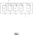
- the figures 1 and 2 schematically represent a measurement system 2 for measuring electrical quantities.
- the system 2 is intended to be associated with an electrical installation, such as an electricity distribution network, for measuring electrical quantities within this electrical installation.
- an electrical installation such as an electricity distribution network
- the system 2 comprises a synchronization module 4, measurement modules 6 and 8 and a data bus 10 to which the synchronization module 4 and the measurement modules 6 and 8 are connected.
- Each measurement module 6, 8 includes a sensor adapted to measure an electrical quantity.
- the electrical quantities can be, in a non-exhaustive manner, electrical voltages, or electrical currents.
- the measurement modules 6, 8 can measure different electrical quantities. The sensor of each measurement module 6 and 8 is therefore chosen accordingly.
- the sensor when the measurement module is intended to measure an electric current, the sensor is a current sensor, such as a Rogowski toroid, or a current transformer, or a Hall effect sensor, or a measurement sensor. by derivation, also called "shunt".
- a current sensor such as a Rogowski toroid, or a current transformer, or a Hall effect sensor, or a measurement sensor. by derivation, also called "shunt".
- the sensor is a voltage sensor, for example a shunt, or a voltage transformer, or a capacitive sensor.
- a first measurement module 6 is configured to measure an electrical voltage and second measurement modules 8 are configured to measure an intensity of an electric current.
- the system 2 comprises a number "m" of the second measurement modules 8, where "m" is an integer greater than or equal to one.
- “m” is an integer greater than or equal to one.
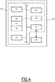
- the electrical installation 20 comprises a primary line 22 and several secondary lines 24.
- the primary line 22 is connected to an electrical source, such as a generator or a distribution transformer, or to another electrical network.
- Each secondary line 24 connects the primary line 22 to a client unit, comprising for example an electrical charge.
- Other configurations are however possible.
- the respective sensors of the measurement modules 6, 8 are here associated with electrical conductors of the electrical installation 20, for example, mounted on or around the electrical conductors forming the lines 22, 24, to measure one or more electrical quantities relating to these power lines 22, 24.
- the first measurement module 6 is mounted on the main line 22 to measure an electrical voltage V.
- the second measurement modules 8 are each mounted on a secondary line 24 to measure an electrical current I (1), I (2), ..., I (m).
- the synchronization module 4 and the connection bus 10 are not illustrated.
- the installation 20 comprises only one electrical phase, but the examples described can be generalized to a polyphase electrical installation for which each line 22, 24 comprises several electrical phases.
- the data bus 10 allows the modules 4, 6 and 8 to exchange data with each other.
- the data bus 10 includes a wire link which forms a physical layer of the data bus 10.
- the data bus 10 is a field bus, for example of CAN type, Modbus TCP or MODBUS.
- the modules 4, 6 and 8 are connected in series by the data bus 10.
- the topology of the data bus 10 may be different and the modules 4, 6 and 8 can be connected for example according to a star topology, or connected in series two by two according to a topology called "daisy chain" in English.
- the synchronization module 4 comprises a logic processing unit 30 (“central processing unit” in English), a computer memory 32, a storage medium 34, a communication interface 36 and a first clock 38, here electrically connected to each other and implemented by electronic circuits and components.
- the logic unit 30 is a microprocessor or a programmable microcontroller.
- the memory 32 and the support 34 are memories by example in the solid state, such as a Flash memory, and each form a computer-readable non-transient data recording medium.
- the communication interface 36 is suitable for being connected to the bus 10 and for this purpose comprises a connector physically connected to the bus 10 and a controller programmed to implement a predefined communication protocol.
- the clock 38 includes an electronic oscillator, for example a crystal oscillator, such as a quartz oscillator.
- the clock 38 can be integrated into the unit 30.
- the clock 38 can be called “main clock”.
- each measurement module 6 and 8 includes a logic processing unit 40, a computer memory 42, a storage medium 44, a communication interface 46, which are for example analogous to logic unit 30, to computer memory 32 , the storage medium 34 and the communication interface 36, respectively.
- the acquisition interface 54 comprises an analog-digital converter and / or a filtering circuit and / or a signal processing circuit.
- Each second clock 48 includes an electronic oscillator, for example a crystal oscillator, such as a quartz oscillator. Each second clock 48 can be called “local clock”.
- each measurement module 6, 8 are here integrated into an electronic control unit 58 which can be separated from the sensor 56.
- the counters 50 and 52 are each implemented by the unit 40 by counting down a time value on the basis of a timing signal supplied by the clock 48.
- the current value of each counter 50 and 52 is stored at least temporarily in memory 42.
- each second clock 48 can have less precision than the first clock 38 and / or be more subject to drift over time than the first clock 38.
- each module 4, 6, 8 is housed in a dedicated device, for example a device provided with its own housing and, for example, with its own power supply.
- different modules 4, 6 and 8 can be integrated within the same device.
- the synchronization module 4 can be integrated alongside a measurement module 6 or 8 in the same device.
- the same device can integrate a measurement module 6 and a measurement module 8.
- the modules 6 and 8 can share the same electronic circuit 58, even if their respective sensors 56 are different.
- the same device can integrate several measurement modules 6 and / or several measurement modules 8, operating simultaneously and independently of each other within the device in order to ensure redundancy of the measurements of the quantity electric.
- each memory 32, 42 and / or each medium 34, 44 stores a software code and / or executable instructions, readable, respectively, by the corresponding logic unit 30 or 40, to automatically implement one or more methods according to any one of the embodiments described and / or envisaged below.
- the modules 4, 6, 8 may include a dedicated electronic circuit, for example of the ASIC type, or a reprogrammable logic circuit, for example of the FPGA type.
- the synchronization module 4 is therefore programmed to periodically transmit synchronization messages on the data bus 10 with the transmission period T com .
- Each synchronization message is sent to all the measurement modules 6 and 8 connected to the data bus 10.
- the synchronization module 4 sends a synchronization message on the bus 10 (step S102) then waits until the end of the transmission period T com (step S104) before d transmitting again a synchronization message, the steps of sending S102 and of waiting S104 being repeated until the process is stopped.
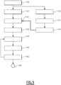
- the diagram 62 represents the data traffic exchanged on the data bus 10 during the operation of the system 2, in particular during three consecutive transmission periods.
- a communication cycle between the modules 4, 6 and 8 on the data bus 10 is defined for each transmission period T com .
- Three communication cycles illustrated for example purposes are here noted “cycle n-1”, “cycle n” and “cycle n + 1", where "n” is a non-zero integer.
- the abscissa axis represents a time line "t” and indicates instants t n-1 , t n , t n + 1 , and t n + 2 .
- the instants t n-1 , t n , t n + 1 correspond, respectively, to the beginning of the cycles n-1, n and n + 1 and the instant t n + 2 corresponds to the end of the cycle n + 1.
- each cycle begins with the transmission of the synchronization message, which here bears the reference 66.
- the synchronization message includes a frame (“BRD (sync)”) which is transmitted by broadcast (“broadcast” in English) to all the modules 6, 8 connected to the bus 10.
- the synchronization message 66 here has a duration denoted t a .
- the synchronization message 66 is immediately followed by a message 68 sent by the or each module 6 and containing one or more voltage values measured by the module 6.
- the message 68 includes a data frame ("BRD (V)") which contains a voltage value measured by this module 6 during the previous cycle.
- Message 68 here has a duration denoted t b .
- the message 68 is followed by a range 70 of duration denoted t c during which the modules 6, 8 can transmit data on the data bus 10.
- the range 70 is followed by a period of silence 72 of duration denoted t d and which marks the end of the cycle.
- t d a period of silence 72 of duration denoted t d and which marks the end of the cycle.
- the modules 6 and 8 are prevented from transmitting data on the data bus 10. This thus prevents the transmission of the following synchronization message 66 from being hampered by the presence of other messages on the data bus 10 at the time of its transmission.
- the sum of the durations t a , t b , t c and t d is equal to the duration of the emission period T com .
- the communication protocol used by the modules 4, 6, 8 to communicate on the data bus 10 may be different, so that the scheduling and / or the type of data exchanged on the bus 10 after the transmission of message 66 can be defined differently.
- messages 68 can be sent by module 6 immediately after each measurement, without necessarily waiting for the next cycle.
- messages 68 can be sent during each communication cycle, each message 68 containing the voltage value (s) measured for the immediately preceding measurement instant.
- the periods of silence 72 can be omitted.
- Line 64 of the timing diagram 60 represents instants at which electrical magnitude measurements are carried out by one of the measurement modules 6, 8.
- the reference S 1 (n-1) indicates the instant at which a first measurement is made by this measurement module 6, 8 during the cycle n-1.
- the reference S 2 (n-1) indicates the instant at which, if necessary, a second measurement is carried out by this same module 6, 8 during the cycle n-1.
- the reference S 1 (n) indicates the instant at which a first measurement is carried out during the cycle n. And so on.
- the waiting time t 1 is counted here by the first counter 50, the current value of which is represented by the duration "T s ".
- the first clock 38 is chosen so as not to exhibit any significant drift during one or more repetitions of the period T com .
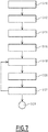
- the first counter 50 is triggered (step S112) and, by means of the clock 48, the time is counted until reaching the first waiting time t 1 .
- the first waiting time t 1 has a predefined value, for example recorded in the storage medium 44.
- the measurement module 6, 8 measures a value S 1 (n-1) of the electrical quantity by means of the sensor 56 (step S116), by example by sampling by means of the acquisition interface 54.
- the measured value S 1 (n-1) is then stored in the memory 42 and / or in the support 44.
- the counter 50 counts the second waiting time T (step S118), in a similar manner to step S112. For example, the counter 50 is reset at the start of step S118.
- the value of the second waiting time T is predefined, for example stored in the support 44.
- step S120 the measurement module 6, 8 measures a second value S 2 (n-1) of the electrical quantity by means of the sensor 56 (step S122), analogous to step S116.
- Steps S118, S120 and S122 can be repeated as many times as necessary when the measurement module 6, 8 must measure more than twice the electrical quantity during each cycle. Otherwise, the method ends in step S124 after the second measurement.
- the number "p" of measurements of the electrical quantity by a module 6, 8 during each cycle is greater than or equal to 1.
- the number of measurements "p" is equal to 2 for each cycle .
- the transmission period T com is chosen according to the number of measurements and the value of the second waiting time T so that the measurements are completed at the end of each cycle.
- steps S118 to S122 are omitted.
- the additional measurements S 2 (n-1), S 2 (n), S 2 (n + 1), ... are not directly triggered by the reception of the synchronization message 66, but depend on the count of the second waiting time by the second clock.
- the second clocks 48 are chosen so as not to exhibit any significant drift during one or more repetitions of the second waiting time T.
- the method of figure 7 when implemented by the first measurement module 6, may also include a step, not illustrated, of sending the message 68 previously described, this message 68 comprising a voltage value previously measured by this first measurement module 6, for example measured during the previous cycle.
- one or more additional steps can be implemented to calculate a composite electrical quantity from one or more of the quantities measured.
- a value of the composite electrical quantity is calculated, for each cycle, from one or more of the electrical quantities measured by measurement modules 6, 8.
- the composite electrical quantity is an electrical power. The calculation is, for example, implemented by the modules 6, 8 themselves or by a dedicated processing unit, not shown, connected to the data bus 10 and implemented by an electronic circuit.
- this power is calculated by each second measurement module 8 from the voltage value measured by the first measurement module 6 and transmitted in message 68 and from the current values measured by this measurement module 8.
- the embodiments of the invention described below thus make it possible to synchronize the measurement of electrical quantities between the various measurement modules 6, 8 of the measurement system 2.
- the electrical quantities can thus be measured simultaneously by the measurement modules 6, 8 of system 2, or almost simultaneously.
- “almost simultaneously”, we mean here measurements made during a time window of duration less than or equal to 50 ⁇ s.
- Such a method is more advantageous than an artificial synchronization based on a time adjustment carried out a posteriori from the phase difference calculated between the voltage and current measurements, that is to say after the measurements have been made by the modules. of measurement.
- phase shift must be determined by taking as reference specific values of the voltage and of the current among the measured values, for example by taking as reference the zero crossing of the current and tension.
- phase shift is frequently distorted by the presence of harmonics in the quantities measured, and / or by deformations of the current and / or voltage signals resulting from upstream filtering of these signals.
- filtering is often required by electromagnetic compatibility standards.
- an external synchronization mechanism aimed at regularly resetting the local clocks of the measurement modules to an external reference clock would consume too much bandwidth, clutter the data bus and be complex to implement, in particular because it would require more sophisticated and therefore more expensive local clocks.
- the embodiments of the invention make it possible to synchronize the measurement modules in a simple and reliable manner, which is advantageous in particular in applications where the measurement modules 6, 8 must be inexpensive to manufacture and maintain and must operate with limited computing resources, for example in applications where the measurement modules 6, 8 must be deployed en masse in large electrical installations 20.
- the manufacturing cost of the measurement modules 6, 8 is thereby reduced.
- the description of the first embodiments can be transposed to that of the second embodiments.
- the same reference numerals designate similar or identical elements, the description of which is not repeated in detail.
- these second embodiments are capable of being implemented by a measurement system 2 as described above, the measurement modules 6, 8 being reprogrammed accordingly.
- the diagram 82 represents the data traffic exchanged on the data bus 10 during the operation of the system 2, in particular during three consecutive transmission periods, in a similar manner to the diagram 62 described above.
- other communication protocols than that described here by way of example can be envisaged.
- Line 84 of the timing diagram 80 represents time intervals T mes separating the reception of two consecutive synchronization messages 66 by the same measurement module 6, 8.
- the reference T n-1 I is the value of the time interval T mes measured during the cycle n-1 between receipt of the synchronization message 66 marking the beginning of cycle n-1 and the reception of the message synchronization 66 marking the start of cycle n.
- the time intervals T mes are counted here by the second counter 52, the current value of which is represented by the duration "T sync ".
- the first and second counters 50, 52 can operate independently of one another.
- the time intervals T mes normally have the same duration as the period T com , the possible durations of measurement, processing and propagation of messages on the bus 10 being considered to be negligible compared to the duration of the period T com .
- Line 86 of the timing diagram 80 represents instants at which measurements of the electrical quantity are carried out by one of the measurement modules 6, 8, in a similar manner to line 64 of the timing diagram 60.
- the reference t 1 (n-2) designates the particular value taken by the first waiting time t 1 during the cycle n-1, the value of which is calculated at the end of the cycle n-2 preceding the cycle n -1.
- the reference t 1 (n-1) designates the particular value taken by the first waiting time t 1 during the cycle n whose value is calculated at the end of the cycle n-1.
- the reference T (n-2) designates the particular value taken by the second waiting time T during the cycle n-1, the value of which is calculated at the end of the cycle n-2. And so on.
- the first waiting time t 1 is determined, for each of the measurement modules 6, 8, following each reception of a synchronization message by this measurement module, from a predetermined calculation formula being a function of the value of the time interval T mes previously measured by this measurement module.
- the first waiting time t 1 is proportional to said value of said time interval T mes with a first predefined proportionality coefficient.
- the first proportionality coefficient is equal to “a / p” where “a” is a numerical value, for example strictly less than 1.
- the first waiting time t 1 (n-1) is equal to the product of the coefficient a / p by the particular value T n-1 mes of the time interval T mes measured during the previous cycle.
- the first waiting time t 1 is calculated for each communication cycle not only as a function of the value of the time interval T mes previously measured but also as a function of a history of values of the first time d waiting t 1 , that is to say previous values of the first waiting time t 1 measured for one or more previous cycles.
- the calculated value of the first waiting time t 1 takes into account an average of the calculated values of the first waiting times t 1 associated with a predefined number of previous cycles.
- this history can be saved in memory 42, 44 of the measurement module 6, 8 and can be updated during each cycle.
- the calculation of the first waiting time t 1 for that cycle can reflect a historic values of the time T measured for my previous cycles.
- this history can be saved in memory 42 or 44 of the measurement module 6, 8 and can be updated during each cycle.
- the second waiting time T is determined, for each of said measurement modules 6, 8, following each reception of the synchronization message. by this measurement module, from a predetermined calculation formula being a function of said time interval T mes previously measured by this measurement module.
- the second waiting time T is proportional to said value of said time interval T mes as a function of a second proportionality coefficient predefined.
- the first proportionality coefficient is equal to "1 / p".
- the second waiting time T (n-1) is equal to the product of the coefficient 1 / p by the time interval T n-1 my measured during the preceding cycle.
- the second waiting time T is calculated for each communication cycle not only as a function of the value of the time interval T mes previously measured but also as a function of a history of values of the second duration of wait T, such as an average of the calculated values of the second wait time T associated with a predefined number of previous cycles.
- this history can be saved in memory 42, 44 of the measurement module 6, 8 and can be updated during each cycle.
- step S130 when one of the second modules 6, 8 receives a synchronization message 66 (step S130), the first counter 50 is triggered (step S132) and, by means of the clock 48, the time is counted until reaching the first waiting time t 1 defined for this cycle.
- step S134 the module 6, 8 measures a value S 1 (n-1) of the electrical quantity by means of the sensor 56 (step S136). Once the first value S 1 (n-1) has been measured, the counter 50 counts down the second waiting time T (step S138). For example, the counter 50 is reset at the start of step S138. Once the second waiting time T is reached (step S140), the module 6, 8 measures a second value S 2 (n-1) of the electrical quantity by means of the sensor 56 (step S142). Steps S138, S140 and S142 can be repeated as many times as necessary when the measurement module 6, 8 must measure more than twice the electrical quantity during each cycle. Otherwise, the method ends at step S144 after the second measurement.
- steps S130 to S144 are similar to steps S110 to S124 previously described.
- the second counter 52 measures the duration separating the reception of two consecutive synchronization messages 66.
- the second counter 52 was started during the previous cycle and counts the time elapsed since the reception of the synchronization message at the start of this previous cycle.
- the module 6, 8 Upon receipt upon receipt of the synchronization message 66, the module 6, 8 stops the second counter 52 and records the current value of this counter as being equal to the time interval T mes (step S150).
- step S152 the second counter 52 is reset to zero then restarted (step S152) and begins to count down the time which elapses, for example until the next iteration of step S150 initiated by the reception of the following synchronization message 66 .
- the value of the first waiting time t 1 and / or the second waiting time T for this cycle is / are calculated as a function of the time interval T mes thus measured.
- the current values of the first waiting time t 1 and / or the second waiting time T recorded in the memory of the module 6, 8 are updated accordingly.
- the calculation of the value of the first waiting time t 1 and / or the second waiting time T for this cycle can take into account, as explained above, d a history of values of the first waiting time t 1 and / or of the second waiting time T and / or of a history of values of the time interval T mes .
- steps S150, S152 and S154 are preferably implemented before step S134, as illustrated in the figure 9 .
- the values of the first and second waiting times T 1 and T can be recalculated for each cycle according to said time interval T mes measured, as in the example described above.
- the first and second waiting times t 1 and T can be recalculated for each cycle according to said time interval T mes measured.
- the second embodiments described above advantageously make it possible to improve the synchronization of the measurements between the different measurement modules 6, 8.
- the oscillation frequency of the second clock 48 of a measurement module 6, 8 slows abnormally compared to a reference clock, then the durations measured by this second clock 48 will appear shorter than they are actually. Thus, the time interval T mes measured by this clock 48 will be perceived as shorter than it actually is. As this time interval is then used to calculate the first waiting time t 1 and, if necessary, the second waiting time T, then the first and second waiting times t 1 and T will be reduced accordingly.
- the error thus made on the calculation of the first and second waiting times t 1 and T will be compensated by the drift of the clock 48, so that the first measurement, even the additional measurements, will ultimately be synchronized with the measurements of the measurement modules 6, 8.
- the third embodiments are similar to the first and second embodiments described above, and differ in particular in that the additional measurements are repeated until the next synchronization message is received. It is therefore understood that in this case the number of measurements, denoted p, is greater than or equal to two.
- the description of the second embodiments can be transposed to that of the third embodiments.
- the same reference numerals designate similar or identical elements, the description of which is not repeated in detail.
- these third embodiments are able to be implemented by a measurement system 2 as described above, the measurement modules 6, 8 being reprogrammed accordingly.
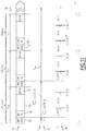
- the diagram 92 represents the data traffic exchanged on the data bus 10 during the operation of the system 2, in particular during three consecutive transmission periods, in a similar manner to the diagram 62 described above.
- other communication protocols than that described here by way of example can be envisaged.
- Line 94 of the timing diagram 90 represents time intervals T mes separating the reception of two synchronization messages 66 consecutive by the same measurement module 6, 8, similarly to line 84 of the timing diagram 80.
- Line 96 of the timing diagram 90 represents instants at which measurements of the electrical quantity are carried out by one of the measurement modules 6, 8, in a similar manner to line 86 of the timing diagram 60.
- the third embodiments are particularly applicable in the case where one of the synchronization messages 66 is not received by a measurement module 6, 8, or is received late. In the example illustrated, the synchronization message of the cycle n + 1 pointed to by the reference 98 is not received.
- the synchronization message 66 is not received, as is the case at the start of the cycle n + 1 in the example of the figure 11 , the measurements of the electrical quantity continue to be implemented based on the second waiting time T (n-1) calculated from the previous cycle and not updated, even when the cycle n is actually finished and that the next n + 1 cycle has started.
- the measurement module 6, 8 concerned is temporarily not resynchronized with the other measurement modules 6, 8.
- the second counter 52 continues to operate, as long as no synchronization message 66 is received.
- step S132 and, where appropriate, step S150 of the method are implemented as previously described, which makes it possible to resynchronize the measurement module concerned. with the other measurement modules.
- this value of the time interval T mes calculated by the second counter 52 is preferably not taken into account subsequently since it is not representative of the interval between the transmission of two synchronization messages 66 consecutive.
- a measured value of the time interval T mes is automatically rejected if the number of measurements made by the measurement module 6, 8 during this time interval T mes is different from a predefined number of measurements, for example greater than the maximum number of measurements p.
- a synchronization error can be detected if a cycle ends prematurely because of the premature reception of a synchronization message, such an error being identified when the number of measurements carried out during this cycle is measured as being less than the number of measurements p.
- the third embodiments described above thus make it possible, in addition to the other advantages, to ensure continuity of operation of the measurement module without distorting the synchronization of the measurements in the event of poor punctual reception of the synchronization message.
- the operating process is therefore more robust in the event of an error. Even if a possible drift from the local clock 48 is temporarily no longer compensated, this occurs over a reduced number of measurement intervals, so that the impact on the reliability of the measurements remains under control.
- a first variable Nsync is defined as indicating the initialization state of the module.
- the variable Nsync can take several predefined states: a first start state, a second start state and a normal operating state.
- a second variable Nmes is defined, the current value of which indicates the number of measurements made by said module 6 or 8.
- the variables Nsync and Nmes are stored in memory 42.
- module 6 or 8 When module 6 or 8 is started, it implements an initialization sequence in which the variable Nsync is initialized to a first value corresponding to the first start state.
- the variable Nmes is initialized to zero.
- the second waiting time T is chosen equal to a local predefined value, for example prerecorded in memory 42 or 44.
- the second counter 52 is triggered.
- the first waiting time t 1 is chosen to be equal to a local predefined value, for example prerecorded in memory 42 or 44, with a view to the next reception of the synchronization message 66.
- the module 6, 8 is then in a first start state, in which the measurement is not synchronized with the other measurement modules and is based on locally defined waiting times.
- One or more measurements of the electrical quantity can then be implemented during steps analogous to steps S142 at each expiration of the first counter 52 at the end of the second duration T, the variable Nmes being incremented during each measurement.
- this situation will change when the first synchronization message 66 is received.
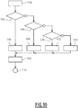
- step S160 the value of the variable Nsync is automatically checked.
- step S162 If the value of the variable Nsync is determined to correspond to the first start state (step S162), then the value of the variable Nsync is changed to the second start state and the values of the first and second waiting times t 1 and T take the predefined values (step S164).
- steps S132 to S142 are implemented with the values of the first and second waiting times t 1 and T thus defined, the variable Nmes being incremented during each measurement of the electrical quantity by the sensor 56 (step S178).
- the module 6, 8 is in a second start state in which the measurement is synchronized with the other measurement modules, but in which the clock is not corrected.
- the process ends at step S180, until reception of the following synchronization message 66.
- step S160 If after step S160 the value of the variable Nsync is determined as corresponding to the second start-up state (step S166), then the value of the variable Nsync is changed to the normal operating state and the values of the first and second duration standby t 1 and T are calculated from the value of the measured time interval T mes (step S168). Then steps S132 and following, as previously described, are implemented with the values of the first and second waiting times t 1 and T thus calculated, the variable Nmes being incremented during each measurement of the electrical quantity by the sensor 56 (step S178).
- the measurement module 6, 8 is in a nominal operating mode in which the measurements are synchronized and any offset from the local clock 48 is compensated. For example, steps S132 and following as described above are implemented.
- step S170 If following the reception of a new synchronization message 66 the variable Nsync is not in one of the start states and the number of measurements Nmes is identified as equal to the number of measurements p (step S170), the module 6, 8 is considered to be always in a nominal operating mode (step S172). Otherwise (step S174), if the variable Nmes has a value different from the number of measurements p, then a synchronization error is considered to have occurred.
- a reset is implemented (step S174), during which the values of the first and second waiting times t 1 and T are each reset to the local preset value previously described.
- the first counter 50 is reset with the local predefined value of the first waiting time t 1 and the second counter 52 is reset to start counting the time interval T mes again .
- the variable Nsync is reset to the second start state.
- the value of the first waiting time t 1 can be adjusted locally for each measurement module 6, 8, to take account of any delays inherent in the measurement circuit or in the communication bus 10, so favoring a simultaneous or almost simultaneous reception of each synchronization message 66 by all the measurement modules 6, 8.
- the measurement modules 6, 8 may not receive the synchronization message 66 at the same time , depending on their position on the data bus 10.
- the waiting time t 1 can be adjusted locally for each measurement module 6, 8, to take account of the time that the synchronization message takes to propagate from step by step between the measurement modules.
- the adjustment may include adding or removing a predefined time in each measurement module 6, 8, this predefined time being specific to each module 6, 8.
- the predefined time is calculated on the basis of the specifications module 6, 8 and / or data bus 10 techniques, or determined after calibration.
- the predefined time is, for example, stored in the memory of module 6, 8.
- the adjustment can be made during manufacture or during the installation of the system 2 by directly choosing a value of the first waiting time t 1 which takes into account any delays previously quantified.
- the adjustment being able to be made during step S152 or step S154, by adding or subtracting the preset time.
- the synchronization message 66 is sent periodically.
- the transmission period T com has a fixed value, for example predefined in advance.
- the synchronization message 66 is not transmitted periodically and the synchronization message 66 is sent with a transmission cycle of variable duration T com .
- the transmission period T com can, at each cycle, take a value chosen from among a plurality of predefined values.
- the transmission period T com alternates between a first duration and a second duration longer than the first duration.
- the synchronization message 66 sent by the module 4 includes data relating to time, this data including for example a value of the first waiting time t 1 indicating the waiting time before the first measurement to be made during the cycle
- the first counter 50 upon receipt of the synchronization message 66, is updated with the value received from the first waiting time t 1 .
- the value of the first waiting time t 1 appearing in the synchronization message 66 is calculated by the module 4.
- the time data contained in the synchronization message 66 can also include the value of the duration T cyc elapsed since the sending of the last synchronization message 66 by the module 4.
- the duration T cyc indicates the duration of the communication cycle that has just ended.
- step S154 can be modified to calculate differently the values of the first waiting time t 1 and the second waiting time T.
- the number of measurements made by the modules 6, 8 is not necessarily the same during each cycle. In other words, the number of measurements can vary from one cycle to another.
- the synchronization message 66 includes data relating to time, as described above, including in particular a value of the first waiting time t 1 and / or a value of the duration T cyc elapsed since the sending of the last synchronization message 66 by the module 4.
- the synchronization message 66 also includes an indicator of the number of measurements made since the last synchronization by said measurement module 6, 8.
- the synchronization module 4 is programmed to count the number of measurements made during each cycle by all or part of the measurement modules 6, 8, then to include the number of measurements thus counted in the synchronization message marking the start of the next cycle.
- this counting is advantageously carried out by counting the number of measured values included in the data message 68 sent, or, for the embodiments in which such a data message 68 is sent immediately after each measurement, by counting the number of data messages 68 sent during each cycle by a module 6, 8.
- knowing the number of measurements received in the synchronization message 66 makes it possible to detect an operating anomaly of the measurement module, for example to determine that a previous synchronization message has not been received. This determination can be made by comparing the number of measurements indicated in the synchronization message 66 received with the number of measurements recorded in the variable Nmes.
Landscapes
- Physics & Mathematics (AREA)
- General Physics & Mathematics (AREA)
- Engineering & Computer Science (AREA)
- Power Engineering (AREA)
- Arrangements For Transmission Of Measured Signals (AREA)
Applications Claiming Priority (1)
| Application Number | Priority Date | Filing Date | Title |
|---|---|---|---|
| FR1873633A FR3090885B1 (fr) | 2018-12-20 | 2018-12-20 | Procédé et système de mesure de grandeurs électriques |
Publications (1)
| Publication Number | Publication Date |
|---|---|
| EP3671231A1 true EP3671231A1 (de) | 2020-06-24 |
Family
ID=67107570
Family Applications (1)
| Application Number | Title | Priority Date | Filing Date |
|---|---|---|---|
| EP19218029.7A Ceased EP3671231A1 (de) | 2018-12-20 | 2019-12-19 | Messverfahren und -system für elektrische grössen |
Country Status (4)
| Country | Link |
|---|---|
| US (1) | US11333689B2 (de) |
| EP (1) | EP3671231A1 (de) |
| CN (1) | CN111351982A (de) |
| FR (1) | FR3090885B1 (de) |
Cited By (1)
| Publication number | Priority date | Publication date | Assignee | Title |
|---|---|---|---|---|
| EP4414721A1 (de) * | 2023-02-13 | 2024-08-14 | Schneider Electric Industries Sas | Verfahren und system zur kalibrierung von spannungsmessungen in einem system zur messung elektrischer grössen |
Citations (4)
| Publication number | Priority date | Publication date | Assignee | Title |
|---|---|---|---|---|
| US20130018609A1 (en) * | 2011-07-13 | 2013-01-17 | Filippenko Alexander S | Power Determination from Separated Voltage and Current Sensors |
| US20140368351A1 (en) * | 2013-06-17 | 2014-12-18 | Schneider Electric Industries Sas | System for calculating an electric quantity, transformer sub-station comprising such a system and method for calculating an electric quantity with such a system |
| GB2527685A (en) * | 2013-02-04 | 2015-12-30 | Mitsubishi Electric Corp | Signal processing apparatus |
| US20160091550A1 (en) * | 2014-09-26 | 2016-03-31 | Schneider Electric Industries Sas | System for detecting an electrical fault and associated method |
Family Cites Families (1)
| Publication number | Priority date | Publication date | Assignee | Title |
|---|---|---|---|---|
| US4156112A (en) * | 1977-12-07 | 1979-05-22 | Control Junctions, Inc. | Control system using time division multiplexing |
-
2018
- 2018-12-20 FR FR1873633A patent/FR3090885B1/fr active Active
-
2019
- 2019-12-16 US US16/715,729 patent/US11333689B2/en active Active
- 2019-12-19 EP EP19218029.7A patent/EP3671231A1/de not_active Ceased
- 2019-12-20 CN CN201911327411.0A patent/CN111351982A/zh active Pending
Patent Citations (4)
| Publication number | Priority date | Publication date | Assignee | Title |
|---|---|---|---|---|
| US20130018609A1 (en) * | 2011-07-13 | 2013-01-17 | Filippenko Alexander S | Power Determination from Separated Voltage and Current Sensors |
| GB2527685A (en) * | 2013-02-04 | 2015-12-30 | Mitsubishi Electric Corp | Signal processing apparatus |
| US20140368351A1 (en) * | 2013-06-17 | 2014-12-18 | Schneider Electric Industries Sas | System for calculating an electric quantity, transformer sub-station comprising such a system and method for calculating an electric quantity with such a system |
| US20160091550A1 (en) * | 2014-09-26 | 2016-03-31 | Schneider Electric Industries Sas | System for detecting an electrical fault and associated method |
Cited By (2)
| Publication number | Priority date | Publication date | Assignee | Title |
|---|---|---|---|---|
| EP4414721A1 (de) * | 2023-02-13 | 2024-08-14 | Schneider Electric Industries Sas | Verfahren und system zur kalibrierung von spannungsmessungen in einem system zur messung elektrischer grössen |
| FR3145808A1 (fr) * | 2023-02-13 | 2024-08-16 | Schneider Electric Industries Sas | Procédé et système de calibration de mesures de tension dans un système de mesure de grandeurs électriques |
Also Published As
| Publication number | Publication date |
|---|---|
| CN111351982A (zh) | 2020-06-30 |
| US20200200802A1 (en) | 2020-06-25 |
| FR3090885B1 (fr) | 2021-05-07 |
| US11333689B2 (en) | 2022-05-17 |
| FR3090885A1 (fr) | 2020-06-26 |
Similar Documents
| Publication | Publication Date | Title |
|---|---|---|
| EP0261118A1 (de) | Energieversorgung für reifenüberwachungsanlage. | |
| FR2960666A1 (fr) | Procede et dispositif de synchronisation et de datation pour equipements d'un reseau de communication de type afdx | |
| WO2015150670A1 (fr) | Procede de mesure de la consommation energetique des branches d'un reseau electrique et equipement de mesure mettant en oeuvre ledit procede | |
| FR2598570A1 (fr) | Circuit retardateur numerique | |
| WO2017080925A1 (fr) | Procede de synchronisation de convertisseurs de donnees par un signal transmis de proche en proche | |
| EP3793142B1 (de) | Kommunikation über can-bus | |
| FR2979506A1 (fr) | Procede de synchronisation d'une grappe de serveurs et grappe de serveurs mettant en œuvre ce procede | |
| EP3593148B1 (de) | Verfahren, flüssigkeitsmessgerät, computerprogramm und speichermittel zur messung einer geschwindigkeit eines fluids | |
| EP3671231A1 (de) | Messverfahren und -system für elektrische grössen | |
| EP4198526B1 (de) | Verfahren und systeme zur bestimmung einer elektrischen grösse in einer elektrischen anlage | |
| WO2010118940A1 (fr) | Transmission bidirectionnelle sans fil de signaux de donnees serie entre un dispositif electronique et un compteur d'energie | |
| EP3798649B1 (de) | Verfahren zur bestimmung der position einer teilentladungsstelle in einem in betrieb befindlichen hochspannungskabel | |
| EP4033680B1 (de) | Verfahren zur synchronisierung von zeitdomänen eines systems auf einem chip | |
| EP2950111B1 (de) | Verfahren zur erkennung der abwesenheit einer verbindung zwischen einem mehrphasigen elektrischen zähler und einem nullleiter | |
| EP3001208B1 (de) | System zum erkennen einer elektrischen störung, und entsprechendes verfahren | |
| EP0632279A1 (de) | Apparat zur Messung der Dauer eines Zeitintervalls | |
| WO2010031952A1 (fr) | Compteur analogique et imageur incorporant un tel compteur | |
| EP3593147B1 (de) | Verfahren zur messung einer geschwindigkeit eines fluids | |
| FR3149092A1 (fr) | Synchronisation de dispositifs d’acquisition de données d’un système de surveillance en ligne d’un réseau de distribution électrique par détection de passages par zéro | |
| FR3073957B1 (fr) | Systeme et procede de datation d'un evenement detecte dans un vehicule automobile | |
| FR3083941A1 (fr) | Systeme de communication bidirectionnel sans-fil | |
| EP3026447B1 (de) | Verfahren und vorrichtung zur bestimmung einer elektrischen scheinleistung, die von einer elektrischen anlage verbraucht wird | |
| EP3242412A1 (de) | Verfahren zur synchronisierung einer elektronischen vorrichtung auf einem periodischen alternativen signal, und entsprechendes telekommunikationsverfahren | |
| EP4344063A1 (de) | Verfahren zur bestimmung der phasenverschiebung zwischen einem ersten, einem ersten elektronischen bauelement empfangenen taktsignal und einem zweiten, elektronischen taktsignal | |
| EP0840185A1 (de) | Genaue Datierung eines Vorfalls erlaubendes Kommunikationsverfahren und Vorrichtung dazu |
Legal Events
| Date | Code | Title | Description |
|---|---|---|---|
| PUAI | Public reference made under article 153(3) epc to a published international application that has entered the european phase |
Free format text: ORIGINAL CODE: 0009012 |
|
| STAA | Information on the status of an ep patent application or granted ep patent |
Free format text: STATUS: THE APPLICATION HAS BEEN PUBLISHED |
|
| AK | Designated contracting states |
Kind code of ref document: A1 Designated state(s): AL AT BE BG CH CY CZ DE DK EE ES FI FR GB GR HR HU IE IS IT LI LT LU LV MC MK MT NL NO PL PT RO RS SE SI SK SM TR |
|
| AX | Request for extension of the european patent |
Extension state: BA ME |
|
| STAA | Information on the status of an ep patent application or granted ep patent |
Free format text: STATUS: REQUEST FOR EXAMINATION WAS MADE |
|
| 17P | Request for examination filed |
Effective date: 20201127 |
|
| RBV | Designated contracting states (corrected) |
Designated state(s): AL AT BE BG CH CY CZ DE DK EE ES FI FR GB GR HR HU IE IS IT LI LT LU LV MC MK MT NL NO PL PT RO RS SE SI SK SM TR |
|
| STAA | Information on the status of an ep patent application or granted ep patent |
Free format text: STATUS: EXAMINATION IS IN PROGRESS |
|
| 17Q | First examination report despatched |
Effective date: 20221123 |
|
| STAA | Information on the status of an ep patent application or granted ep patent |
Free format text: STATUS: THE APPLICATION HAS BEEN REFUSED |
|
| 18R | Application refused |
Effective date: 20240620 |