EP3671984B1 - Dispositif de commutation comprenant une pièce porteuse et comportant un composant d'une électronique disposé dans la pièce porteuse - Google Patents
Dispositif de commutation comprenant une pièce porteuse et comportant un composant d'une électronique disposé dans la pièce porteuse Download PDFInfo
- Publication number
- EP3671984B1 EP3671984B1 EP18214108.5A EP18214108A EP3671984B1 EP 3671984 B1 EP3671984 B1 EP 3671984B1 EP 18214108 A EP18214108 A EP 18214108A EP 3671984 B1 EP3671984 B1 EP 3671984B1
- Authority
- EP
- European Patent Office
- Prior art keywords
- switching device
- bearing
- component
- bearing plate
- bearing part
- Prior art date
- Legal status (The legal status is an assumption and is not a legal conclusion. Google has not performed a legal analysis and makes no representation as to the accuracy of the status listed.)
- Active
Links
Images


Classifications
-
- H—ELECTRICITY
- H01—ELECTRIC ELEMENTS
- H01H—ELECTRIC SWITCHES; RELAYS; SELECTORS; EMERGENCY PROTECTIVE DEVICES
- H01H85/00—Protective devices in which the current flows through a part of fusible material and this current is interrupted by displacement of the fusible material when this current becomes excessive
- H01H85/02—Details
- H01H85/0241—Structural association of a fuse and another component or apparatus
-
- H—ELECTRICITY
- H02—GENERATION; CONVERSION OR DISTRIBUTION OF ELECTRIC POWER
- H02B—BOARDS, SUBSTATIONS OR SWITCHING ARRANGEMENTS FOR THE SUPPLY OR DISTRIBUTION OF ELECTRIC POWER
- H02B1/00—Frameworks, boards, panels, desks, casings; Details of substations or switching arrangements
- H02B1/18—Disposition or arrangement of fuses
-
- H—ELECTRICITY
- H02—GENERATION; CONVERSION OR DISTRIBUTION OF ELECTRIC POWER
- H02B—BOARDS, SUBSTATIONS OR SWITCHING ARRANGEMENTS FOR THE SUPPLY OR DISTRIBUTION OF ELECTRIC POWER
- H02B1/00—Frameworks, boards, panels, desks, casings; Details of substations or switching arrangements
- H02B1/20—Bus-bar or other wiring layouts, e.g. in cubicles, in switchyards
- H02B1/21—Bus-bar arrangements for rack-mounted devices with withdrawable units
-
- H—ELECTRICITY
- H01—ELECTRIC ELEMENTS
- H01H—ELECTRIC SWITCHES; RELAYS; SELECTORS; EMERGENCY PROTECTIVE DEVICES
- H01H85/00—Protective devices in which the current flows through a part of fusible material and this current is interrupted by displacement of the fusible material when this current becomes excessive
- H01H85/02—Details
- H01H85/0241—Structural association of a fuse and another component or apparatus
- H01H2085/0291—Structural association with a current transformer
-
- H—ELECTRICITY
- H01—ELECTRIC ELEMENTS
- H01H—ELECTRIC SWITCHES; RELAYS; SELECTORS; EMERGENCY PROTECTIVE DEVICES
- H01H31/00—Air-break switches for high tension without arc-extinguishing or arc-preventing means
- H01H31/02—Details
- H01H31/12—Adaptation for built-in fuse
- H01H31/122—Fuses mounted on, or constituting the movable contact parts of, the switch
Definitions
- the invention relates to a switching device, in particular a switching strip for low-voltage, high-performance fuses (NH fuses).
- NH fuses are also referred to as NH fuse-links.
- NH fuse-links For example, from the DE 38 12 504 A1 an NH load switch known.
- switching devices are equipped with electronic components for recording and processing measured values, for example in order to permanently monitor or measure all current and voltage-relevant data.
- current transformers can be used in such switching devices, which are used to measure the current flowing through the switching device.
- one or more current transformers are used. With the help of a corresponding current transformer, the measurement of the respective phase can be carried out continuously without interrupting the current.
- the current transformer can be a commercially available current transformer with a core, but so-called Rogowski coils are also used as current transformers.
- the current transformer (s) are often arranged within the switching device.
- Current sensors such as Hall sensors, are used.
- other sensors such as temperature sensors or humidity sensors, can also be considered as components of electronics.
- the fuse strip or circuit breaker strip has a carrier part and an electronics component arranged in the carrier part, namely a current transformer, the carrier part having a lower part and a bearing part in the form of a cover that can be connected to the lower part, with at least one pair on a front side of the lower part of contacts is arranged, which is used to hold an electrical fuse or a disconnecting knife.
- the contacts are connected to current conductors stored in the lower part, which in turn are connected to current outlets and current inputs.
- the at least one current transformer is assigned to an arrangement of contact and current conductor, the arrangement of contact and current conductor penetrating an opening in the current transformer.
- the arrangement of contact and current conductor is designed in such a way that the current transformer can be plugged onto the arrangement of contact and current conductor on the front.
- the cross section of the opening of the current transformer is larger than the cross section of the arrangement of contacts and current conductors in a plug-on area of the arrangement.
- the EP 1,387,454 relates to a device unit with a contact for pluggable connection to a stationary busbar, the contact being arranged outside of a housing which accommodates a switching unit.
- the device unit has a housing, a cover and a current detection device, a space formed between the cover and the housing serving to accommodate the current detection device.
- the object of the present invention is to develop a switching device having the features of the preamble of claim 1 in such a way that the switching device can be easily equipped with electronic components, in particular an already existing switching device can be retrofitted in a simple manner with components of electronics.
- the switching device which has the features of claim 1.
- the switching device according to the invention has a carrier part and an electronics component arranged in the carrier part, the carrier part having a lower part and a bearing part that can be connected to the lower part. At least one pair of contacts is arranged on a front side of the lower part for receiving an electrical fuse or a cutting knife.
- the electronics component is stored in the bearing part, the electronics component being releasably attached to the bearing part, the bearing part with the electronics component stored in the bearing part being attachable to the lower part from the front of the lower part .
- front side is understood here to mean a side of the lower part of the switching device facing the operator of the switching device.
- the switching device can not only be easily provided with the electronics component during the initial installation, but it is also possible to easily retrofit this switching device with the electronics component when the switching device is installed.
- the bearing part is first removed from the lower part when the switching device is installed.
- an upper part connected to the carrier part, in particular the lower part may have to be removed before the bearing part is removed from the lower part.
- the bearing part is provided with the corresponding electronic component, this being particularly uncomplicated since the bearing part can be handled independently of the other components of the switching device. So are for one In a state of the bearing part released from the lower part, the user of the switching device has uncomplicated access to both the side of the bearing part facing away from or facing away from the lower part and a side of the bearing part facing or facing the lower part.
- the typically weight-intensive components of the switching strip such as the contacts and possibly electrical conductors connected to the contacts, are stored in the lower part, which does not have to be handled for the purpose of retrofitting or equipping the switching device with the electronic components.
- the retrofitting or equipping of the switching device with the electronics takes place on the bearing part, which is simple and uncomplicated to handle and which is used to mount the electronic components.
- the bearing part fitted with the electronic component can be slipped onto the lower part from the front of the lower part. Accordingly, a switching device can be equipped or retrofitted with an electronic component in a particularly simple manner.
- bearing part can be plugged onto the lower part along a straight line from the front side of the lower part.
- the contacts are preferably connected to current conductors stored in the lower part.
- the electronic component can in particular be a component for measuring the current or voltage of a current flowing through the corresponding contact or the corresponding current conductor or of a voltage applied to the contact or the current conductor.
- the component of the electronics can be a component for tapping off a voltage applied to the contact or the current conductor. For example, to supply another component of the electronics with voltage or current.
- Current sensors such as Hall sensors, can also be used as components of electronics.
- sensors such as a temperature sensor or a humidity sensor, can also be considered as components of electronics.
- the electronic component is preferably a component that interacts with the contact or the current conductor.
- component is also understood to mean an arrangement of components, for example a device for recording measurement data and the cabling or connection line connected therewith.
- the retrofitting or equipping of the switching device with the component of the electronics is particularly easy and uncomplicated, since the necessary cabling can be carried out separately in the bearing part.
- the lower part is preferably free of any electronic components. It is considered to be particularly advantageous if all of the electronic components that can be arranged in the carrier part are or can be stored in the bearing part.
- the lower part can be arranged with a rear side opposite the front side on a busbar, in particular on a busbar system.
- the inventive design of the switching device even with a switching device connected to a busbar, retrofitting the switching device with the electronic component is uncomplicated, since the component can be retrofitted with the Support part, in particular the lower part, connected upper part, only the bearing part has to be detached from the lower part and retrofitting can be carried out on the freely manageable bearing part, as a result of which the lower part does not have to be accessible, apart from the dismantling of the bearing part.
- the bearing part can be moved to another location for the purpose of equipping or retrofitting the component.
- the switching device has an upper part, the upper part being able to be arranged on the front of the carrier part.
- the upper part can preferably be plugged onto the carrier part, in particular onto the lower part.
- the bearing part is arranged between the upper part and the lower part, in particular an edge region of the bearing part is mounted in a clamping manner between the upper part and the lower part, preferably a side wall of the upper part and the lower part.
- the upper part can preferably be connected to the lower part, in particular it can be connected in a latching manner. It is but it is also quite conceivable that the upper part and the lower part have interlocking means that interact with one another.
- the bearing part can preferably be inserted into the lower part in a latching manner.
- the bearing part is clipped to the lower part.
- the bearing part has a bearing plate, the respective contact passing through a through opening in the bearing plate.
- the contacts of the carrier part protrude on the front side with respect to the bearing plate.
- the bearing part has in each case a cover hood for covering the respective contact. It is considered to be particularly advantageous if the respective cover hood is detachably connected to the bearing plate.
- the respective cover hood is preferably connected to the bearing plate in a latching manner.
- An embodiment with cover hoods detachable from the bearing plate enables the user in a particularly simple manner to arrange a component of the electronics in a cover area covered by the cover hood and thus to arrange it in an area of the corresponding contact of the carrier part.
- the electronic component to be arranged in the cover area can be, for example, a voltage tap which makes contact with the corresponding contact of the carrier part when the bearing part is plugged onto the lower part.
- an embodiment with cover hoods that can be detached from the bearing plate allows the user access to the corresponding contact without having to completely dismantle the bearing part from the lower part.
- the electronics component has a current transformer or a current sensor, with an arrangement of contact and current conductor, an opening in the current transformer or an opening in the current sensor when the bearing part is plugged onto the lower part interspersed.
- the current transformer can be a Rogowski coil, for example.
- the current sensor can be a Hall sensor, for example.
- the contact and / or the arrangement of contact and current conductor has a plug-on area for attaching the current transformer or the current sensor to the contact and / or the arrangement of contact and current conductor, the cross section of the opening of the current transformer or an opening of the current sensor is larger than the cross section of the contact and / or the arrangement of contact and current conductor in the plug-on area.
- the current transformer or the current sensor is arranged on a side of the bearing part facing the lower part, in particular on a side of the bearing plate facing the lower part.
- the current transformer or the current sensor can preferably be inserted into the bearing part, preferably from the side of the bearing part facing the lower part, into the bearing part.
- the electronic component has a voltage tap for tapping a voltage on one of the contacts and / or on one of the current conductors.
- the voltage tap mounted in the bearing part makes contact with the contact and / or the current conductor when the bearing part is slipped on.
- the voltage tap is preferably arranged on a side of the bearing part facing away from the lower part, in particular on a side of the bearing plate facing away from the lower part.
- the voltage tap can preferably be plugged into the bearing part, in particular from the side of the bearing part facing away from the lower part, into the bearing part.
- the voltage tap is arranged in a covering area of the bearing part covered by the covering hood, the contact also being arranged in the covering area of the covering hood when the bearing part is plugged onto the lower part.
- the bearing part covers the conductors and / or the contacts of the carrier part from the front.
- the bearing part forms a cover part.
- the bearing part in particular the bearing plate, has a channel for receiving a connection line or cabling of the electronics component.
- the channel is designed to be open on one side. This enables the connection line or the cabling to be inserted particularly easily into the bearing part. It is considered to be particularly advantageous if the channel is designed as a channel open to the side facing away from the lower part.
- the upper part covers the channel open to the side, in particular covers the channel open to the side facing away from the lower part.
- the electronic component is releasably fastened to the bearing part, in particular the bearing plate, for example by means of separate fastening means, such as a screw, for example, to the bearing part or the bearing plate.
- the electronic component can be connected in a latching manner to the bearing part, in particular the bearing plate, and can thus be fastened or held on the bearing part.
- the electronic component has a holding structure and the bearing part, in particular the bearing plate, has a counter-structure corresponding to the holding structure, for holding the component on the bearing part, in particular for holding the component on the bearing plate.
- the component can be connected to the bearing part or the bearing plate in a particularly simple manner, in particular the component can be inserted into the bearing part or the bearing plate in a latching manner.
- the holding structure and the counter structure are designed as a clip connection. This enables the component to be attached and detached from the bearing part or the bearing plate in a particularly simple manner.
- connection lines of the electronic component are preferably arranged on a side of the bearing part facing away from the lower part, preferably arranged on a side of the bearing plate facing away from the lower part.
- the connection lines are particularly easily accessible from the front, so that a particularly rapid checking of the function of the connection lines and, if necessary, an exchange or relocation of the connection lines can also take place when the bearing part is connected to the lower part.
- the channel receiving the connection lines is formed on a side of the bearing part facing away from the lower part, in particular on a side of the bearing plate facing away from the lower part.
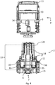
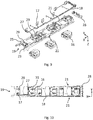
- the Figures 1 to 10 show a switching device 1, in the present case a switching strip for NH fuses, also referred to as an NH fuse switching strip.
- the switching device 1 has a carrier part 2 and an upper part 9 that can be connected to the carrier part 2, three covers 10 being movably supported in the upper part 9.
- the respective cover 10 has a cover part 30 and a switch lever 11, wherein the cover part 30 can be moved from a first end position into a second end position by pivoting the switch lever 11.
- An electrical fuse or a separating knife can be stored in the cover part 30.
- the carrier part 2 has a lower part 3 and a bearing part 4 that can be inserted into the lower part.
- the cover part 30 When the cover part 30 is moved from the first end position to the second end position, the electrical fuse or the cutting blade is retracted into the corresponding pair of contacts 5 or, when moving from the second end position to the first end position, the electrical fuse or the cutting blade is removed the corresponding pair of contacts 5 extended.
- the cover parts 30 are in the second end position.
- the contacts 5 are connected to current conductors 8 stored in the lower part 3.
- the current conductor 8 connected to one contact 5 of the respective pair of contacts 5 can be connected in the area of an end face 34 of the lower part 2 to an access line as a power supply. This area is provided with a terminal compartment cover 33.
- the current conductor 8 connected to the other contact 5 of the respective pair of contacts 5 can be connected on a rear side 7 opposite the front side 6 to a busbar 32 as a current outlet, as shown in FIG Figure 1 is shown.
- the switching device 1 has an electronics component 16, 17, 18 arranged in the bearing part 4, the bearing part 4 together with the electronic components 16, 17, 18 stored in the bearing part 4 from the front 6 of the lower part 3 along the Arrow 12 can be plugged onto the lower part 3.
- the components 16, 17, 18 of the electronics have several individual elements, namely three current transformers 16, six voltage taps 17 and several connection lines 18.
- the respective current transformer 16 is assigned to a contact 5 of the respective pair of contacts 5, the corresponding contact 5 passing through an opening 31 of the current transformer 16 in the mounted position.
- the contact 5 has a plug-on area 13 for plugging the current transformer 16 onto the contact 5 at the front, the cross-section of the opening 31 of the current transformer 16 being larger than the cross-section of the contact 5 in the plug-on area 13 the bearing part 4 mounted current transformers 16 possible.
- the respective contact 5 has, in the attachment direction of the bearing part 4, a first section 14 for receiving the contact blade 26 of the electrical fuse and a second section 15 for receiving the current transformer 16. The sections 14 and 15 thus form the plug-on area 13 for plugging the current transformer 16 onto the contact 5 at the front.
- the contact 5 has two legs, with the contact blade 26 in the first Section 14 can be inserted between the two legs and the contact blade 26 arranged in the first section 14 contacts the two legs on mutually facing sides.
- the first section 14 thus serves to receive the contact blade 26 on the inside.
- the current transformer 16 is arranged outside the contact 5, in the present case the current transformer 16 encloses the second section 15.
- one of the voltage taps 17 is assigned to each of the six contacts 5, the respective voltage tap 17 having a spring contact, this spring contact making contact with the corresponding contact 5 when the switching device 1 is in an assembled state.
- connection lines 18 are also stored in the bearing part 4 and are connected to the current transformers 16 or the voltage taps 17 and are brought together in a socket 28, this socket 28 forming part of the bearing part 4 in the present case.
- both the lower part 3 and the upper part 9, together with the covers 10 stored therein, are free of any electronic components. Accordingly, all components 16, 17, 18 of the electronics of the switching device are stored in the bearing part 4 of the carrier part 2.
- the switching device 1 has further electronic components, for example a measuring circuit board. These further components are preferably stored in the upper part 9.
- all of the electronic components arranged or to be arranged in the carrier part 2 are stored or can be stored in the bearing part 4, thus the lower part 3 is free of any electronic components.
- the current transformers 16 and the voltage taps 17 can be inserted into the bearing part 4.
- the bearing part 4 has a bearing plate 19, the respective contact 5 passing through a through opening 29 of the bearing plate 19 when the bearing part 4 is in the state when the bearing part 4 is pushed onto the lower part 3. Furthermore, the bearing part 4 each has a cover 20 for covering the respective contact 5 penetrating the bearing plate 19, the respective cover 20 being connected or connectable to the bearing plate 19 in a latching manner.
- the bearing plate 19 can be connected in a locking manner to the lower part 3 and the respective cover hood 20 can in turn be connected in a locking manner to the bearing plate 19.
- the locking connections are designed as clip connections.
- the respective current transformer 16 is arranged on a side of the bearing part 4 facing the lower part 3, in the present case it can be inserted into the bearing plate 19 from the side of the bearing plate 19 facing the lower part 3.
- the respective current transformer 16 has, on its side facing the bearing part 4, four protruding holding structures 22, which can be inserted into counter-structures 23 formed in the bearing plate 19 and corresponding to the holding structures 22, in order to hold the current transformer 16 in the bearing plate 19.
- the Holding structures 22 and the corresponding counter-structures 23 in the present case form a clip connection. This enables the current transformer 16 to be connected to the bearing plate 19 and thus to the bearing part 4 in a particularly simple manner.
- the voltage taps 17 are arranged on a side of the bearing plate 19 facing away from the lower part 3 and thus on the side of the bearing plate 19 opposite the voltage taps 16.
- the voltage taps 17 can be inserted into the bearing plate 19 from the side of the bearing plate 19 facing away from the lower part 3.
- the bearing plate 19 has a counter structure 23 in the form of a receptacle, into which the respective voltage tap 17 can be inserted, the counter structure 23 interacting in a clamping manner with a printed circuit board of the voltage tap 17, in so far the printed circuit board of the voltage tap 17 forms a holding structure 22 cooperating with the counter structure 23 for holding the respective voltage tap 17 in the bearing plate 19.
- the bearing part 4 specifically the bearing plate 19 and the covering hoods 20 attached to it, is designed in such a way that the bearing part 4 covers the electrical conductors 8 and the contacts 5 on the front.
- the bearing part 4 forms a cover part of the carrier part 2 for covering the front side of the conductors 8 and contacts 5 arranged in the lower part 3
- Holding structure 24 and the bearing plate 19 has a counter structure 25 corresponding to the holding structure 24.
- the bearing plate 19 has a channel 21 for receiving the connection lines 18, the channel 21 facing the side facing away from the lower part 3 is open.
- connection lines 18 This enables the connection lines 18 to be laid in the bearing plate 19 in a particularly simple manner.
- the connecting lines 18 are led out of the bearing plate 19 at one end of the bearing plate 19 and bundled in the socket 28, this socket 28 in turn being connectable to the bearing plate 19, in the present case being insertable into the bearing plate 19.
- the bearing plate 19 has two parallel channels 21, the channels 21 being formed on opposite edge regions of the bearing plate 19, one of the channels 21 having a smaller longitudinal extent than the other channel 21.
- the upper part 9 covers the open channels 21 on the side of the bearing plate 19 facing away from the lower part 3.
- the connection lines 18 laid or arranged in the channels 21 are particularly well protected against forces acting from the outside and an unintentional detachment of the connection lines 18 from the channel 21 is prevented by the upper part 9.
- the bearing plate 19 has a removable cover plate 27 in the area of each hood 20 or in the area of the mounting of the respective current transformer 16 in the bearing plate 19.
- this cover plate 27 can be removed, whereby a substantially rectangular hole is formed there.
- the data relating to the technical specification of the current transformer 16, which are printed on the side of the current transformer 16 facing the bearing part 4 can be viewed by a user on the front. This enables the user to check in a particularly simple manner whether and what type of current transformers 16 are installed in the switching device 1.
- the switching device 1 can be connected to the component in a particularly simple manner 16, 17, 18 of the electronics or an existing switching device 1 can be retrofitted particularly easily with a corresponding component 16, 17, 18 of the electronics, since the actions to be taken for the purpose of providing the switching device 1 with the components 16, 17, 18 of the electronics depend on the bearing part 4 separable from the lower part 3 can take place.
Landscapes
- Engineering & Computer Science (AREA)
- Power Engineering (AREA)
- Details Of Connecting Devices For Male And Female Coupling (AREA)
- Switch Cases, Indication, And Locking (AREA)
Claims (15)
- Dispositif de commutation (1), en particulier barrette de commutation pour fusibles à basse tension à haute performance, ledit dispositif de commutation comportant une pièce porteuse (2) et un composant (16, 17, 18) d'une électronique qui est disposé dans la pièce porteuse (2), la pièce porteuse (2) comportant une partie inférieure (3) et une partie de support (4) qui peut être reliée à la partie inférieure (3), au moins une paire de contacts (5) étant disposée sur un côté avant (6) de la partie inférieure (3) et destinée à recevoir un fusible électrique ou un couteau de sectionnement,
caractérisé en ce que
le composant (16, 17, 18) de l'électronique est logé dans la partie de support (4), le composant (16, 17, 18) de l'électronique étant fixé de manière amovible à la partie de support (4), la partie de support (4), pourvue du composant (16, 17, 18) de l'électronique, logée dans la partie de support (4), pouvant être enfichée sur la partie inférieure (3) depuis le côté avant (6) de la partie inférieure (3). - Dispositif de commutation (1) selon la revendication 1, l'un au moins des contacts (5) étant relié à un conducteur de courant (8) logé dans la partie inférieure (3) .
- Dispositif de commutation (1) selon la revendication 1 ou 2, la partie inférieure (3) pouvant être disposée avec un côté arrière (7), opposé au côté avant (6), sur une barre collectrice (32), en particulier sur un système de barres collectrices.
- Dispositif de commutation (1) selon l'une des revendications 1 à 3, le dispositif de commutation (1) comportant une partie supérieure (9), la partie supérieure (9) pouvant être disposée du côté avant sur la pièce porteuse.
- Dispositif de commutation (1) selon l'une des revendications 1 à 4, la partie de support (4) comportant une plaque d'appui (19), le contact respectif (5) passant par une ouverture traversante (29) de la plaque d'appui (19) .
- Dispositif de commutation (1) selon l'une des revendications 1 à 5, la partie de support (4) comportant un capot de recouvrement (20) destiné à recouvrir le contact respectif (5), en particulier le capot de recouvrement (20) étant relié de manière amovible à la plaque d'appui (19), de préférence le capot de recouvrement (20) étant relié par encliquetage à la plaque d'appui (19).
- Dispositif de commutation (1) selon l'une des revendications 1 à 6, le composant (16, 17, 18) de l'électronique comportant un transformateur de courant (16) ou un capteur de courant, lorsque la partie de support (4) est enfichée sur la partie inférieure (3), le contact (5) ou un ensemble contact (5) et conducteur de courant (8) passant par une ouverture (31) du transformateur de courant (16) ou une ouverture du capteur de courant.
- Dispositif de commutation (1) selon la revendication 7, le transformateur de courant (16) ou le capteur de courant étant disposé sur un côté de la partie de support (4) qui est dirigé vers la partie inférieure (3), en particulier sur un côté de la plaque d'appui (19) qui est dirigé vers la partie inférieure (3).
- Dispositif de commutation (1) selon l'une des revendications 1 à 8, le composant (16, 17, 18) de l'électronique comportant une prise de tension (17) destinée à prendre une tension sur l'un des contacts (5) et/ou sur l'un des conducteurs de courant (8).
- Dispositif de commutation (1) selon la revendication 9, la prise de tension (17) étant disposée sur un côté de la partie de support (4) qui est opposé à la partie inférieure (3), en particulier sur un côté de la plaque d'appui (19) qui est opposé à la partie inférieure (3).
- Dispositif de commutation (1) selon l'une des revendications 1 à 10, la partie de support (4) recouvrant du côté avant les conducteurs (8) et/ou les contacts (5).
- Dispositif de commutation (1) selon l'une des revendications 1 à 11, la partie de support (4), en particulier la plaque d'appui (19), comportant un canal (21) destiné à recevoir une ligne de raccordement (18) du composant (16, 17, 18) de l'électronique, en particulier le canal (21) étant conçu comme un canal (21) ouvert en direction du côté qui est opposé à la partie inférieure (3).
- Dispositif de commutation (1) selon les revendications 4 et 12, la partie supérieure (9) recouvrant le canal (21) ouvert en direction du côté qui est opposé à la partie inférieure (3).
- Dispositif de commutation (1) selon l'une des revendications 1 à 13, le composant (16) de l'électronique comportant une structure de retenue (22) et la partie de support (4), en particulier la plaque d'appui (19), comportant une structure homologue (23) correspondant à la structure de retenue (22) et destinée à maintenir le composant (16) sur la partie de support (4), en particulier pour maintenir le composant (16) sur la plaque d'appui (19).
- Dispositif de commutation (1) selon l'une des revendications 1 à 14, les lignes de raccordement (18) du composant (16, 17, 18) de l'électronique étant disposées sur un côté de la partie de support (4) qui est opposé à la partie inférieure (3), en particulier sur un côté de la plaque d'appui (19) qui est opposé à la partie inférieure (3).
Priority Applications (3)
| Application Number | Priority Date | Filing Date | Title |
|---|---|---|---|
| ES18214108T ES2874234T3 (es) | 2018-12-19 | 2018-12-19 | Dispositivo de conmutación que presenta una parte de soporte y que presenta un componente de un sistema electrónico dispuesto en la parte de soporte |
| EP18214108.5A EP3671984B1 (fr) | 2018-12-19 | 2018-12-19 | Dispositif de commutation comprenant une pièce porteuse et comportant un composant d'une électronique disposé dans la pièce porteuse |
| PL18214108T PL3671984T3 (pl) | 2018-12-19 | 2018-12-19 | Urządzenie przełączające składające się z części nośnej i zawierające element elektroniki umieszczony w części nośnej |
Applications Claiming Priority (1)
| Application Number | Priority Date | Filing Date | Title |
|---|---|---|---|
| EP18214108.5A EP3671984B1 (fr) | 2018-12-19 | 2018-12-19 | Dispositif de commutation comprenant une pièce porteuse et comportant un composant d'une électronique disposé dans la pièce porteuse |
Publications (2)
| Publication Number | Publication Date |
|---|---|
| EP3671984A1 EP3671984A1 (fr) | 2020-06-24 |
| EP3671984B1 true EP3671984B1 (fr) | 2021-03-31 |
Family
ID=64746204
Family Applications (1)
| Application Number | Title | Priority Date | Filing Date |
|---|---|---|---|
| EP18214108.5A Active EP3671984B1 (fr) | 2018-12-19 | 2018-12-19 | Dispositif de commutation comprenant une pièce porteuse et comportant un composant d'une électronique disposé dans la pièce porteuse |
Country Status (3)
| Country | Link |
|---|---|
| EP (1) | EP3671984B1 (fr) |
| ES (1) | ES2874234T3 (fr) |
| PL (1) | PL3671984T3 (fr) |
Families Citing this family (1)
| Publication number | Priority date | Publication date | Assignee | Title |
|---|---|---|---|---|
| EP4068323B1 (fr) * | 2021-03-31 | 2025-05-14 | Jean Müller GmbH Elektrotechnische Fabrik | Dispositif destiné à être agencé sur des barres de distribution, comprenant un dispositif de commutation et un module électronique |
Family Cites Families (5)
| Publication number | Priority date | Publication date | Assignee | Title |
|---|---|---|---|---|
| DE3812504A1 (de) | 1988-04-15 | 1989-10-26 | Mueller Jean Ohg Elektrotech | Nh-sicherungslastschaltleiste |
| DE29705224U1 (de) * | 1997-03-22 | 1997-06-26 | Jean Müller GmbH Elektrotechnische Fabrik, 65343 Eltville | Einrichtung mit einer NH-Sicherungs- oder NH-Lastschaltleiste sowie einem Wandler |
| DE50200287D1 (de) * | 2002-10-17 | 2004-04-15 | Mueller Jean Ohg Elektrotech | Geräteeinheit mit einem Kontakt zum steckbaren Verbinden mit einer ortsfesten Stromschiene |
| DE102007051419A1 (de) * | 2007-10-25 | 2009-04-30 | Efen Gmbh | NH-Sicherungslasttrenner mit Stromwandler |
| EP2546856B1 (fr) | 2011-07-12 | 2016-05-11 | Jean Müller GmbH Elektrotechnische Fabrik | Baguette pour fusibles NH |
-
2018
- 2018-12-19 ES ES18214108T patent/ES2874234T3/es active Active
- 2018-12-19 EP EP18214108.5A patent/EP3671984B1/fr active Active
- 2018-12-19 PL PL18214108T patent/PL3671984T3/pl unknown
Non-Patent Citations (1)
| Title |
|---|
| None * |
Also Published As
| Publication number | Publication date |
|---|---|
| EP3671984A1 (fr) | 2020-06-24 |
| PL3671984T3 (pl) | 2021-11-22 |
| ES2874234T3 (es) | 2021-11-04 |
Similar Documents
| Publication | Publication Date | Title |
|---|---|---|
| DE10045498C2 (de) | Elektrische Reihenklemme | |
| DE102005050267B4 (de) | Reihenklemme | |
| DE102015218108B4 (de) | Schaltgerät | |
| EP3671786B1 (fr) | Agencement d'une pièce de support, d'une pièce supérieure et d'un couvercle d'un dispositif de commutation pourvu de composants d'une électronique intégrés dans ledit agencement | |
| EP2546856B1 (fr) | Baguette pour fusibles NH | |
| EP2614515B1 (fr) | Appareil de commutation et accessoire du côté connexion | |
| EP2715871B1 (fr) | Dispositif de contrôle et de connexion | |
| DE202010017635U1 (de) | Stromwandlereinheit | |
| EP1912285B1 (fr) | Appareil électrique ou électronique | |
| EP3320583B1 (fr) | Borne de connexion | |
| EP3671984B1 (fr) | Dispositif de commutation comprenant une pièce porteuse et comportant un composant d'une électronique disposé dans la pièce porteuse | |
| DE102013212335A1 (de) | Schieber für ein modulares Reiheneinbaugerät, modulares Rei-heneinbaugerät sowie Sammelschienenverbund | |
| DE102006049772B4 (de) | Installationsschaltgerät | |
| EP4068323B1 (fr) | Dispositif destiné à être agencé sur des barres de distribution, comprenant un dispositif de commutation et un module électronique | |
| EP1387454B1 (fr) | Dispositif avec contact enfichable pour raccordement à une barre omnibus fixe | |
| DE102012203554A1 (de) | Sammelschienenabgreifklemme | |
| EP2511988B1 (fr) | Dispositif de réception de ligne avec décharge de traction | |
| DE102010041197A1 (de) | Tragschiene und Elektroinstallationsverteiler | |
| EP2988312B1 (fr) | Module de fusible | |
| EP1032005B1 (fr) | Installation électrique | |
| DE2604356C3 (de) | Anschlußvorrichtung für Sicherungsautomaten | |
| EP3168850B1 (fr) | Dispositif d'isolation et disjoncteur électromécanique | |
| DE10216371A1 (de) | Hilfsschalter | |
| DE4327172C2 (de) | Vorrichtung zur lösbaren Befestigung mindestens eines elektrischen Bauteils an einer Profilschiene | |
| DE2900357A1 (de) | Ueberbrueckungseinrichtung fuer einen elektrozaehler |
Legal Events
| Date | Code | Title | Description |
|---|---|---|---|
| PUAI | Public reference made under article 153(3) epc to a published international application that has entered the european phase |
Free format text: ORIGINAL CODE: 0009012 |
|
| STAA | Information on the status of an ep patent application or granted ep patent |
Free format text: STATUS: REQUEST FOR EXAMINATION WAS MADE |
|
| 17P | Request for examination filed |
Effective date: 20191115 |
|
| AK | Designated contracting states |
Kind code of ref document: A1 Designated state(s): AL AT BE BG CH CY CZ DE DK EE ES FI FR GB GR HR HU IE IS IT LI LT LU LV MC MK MT NL NO PL PT RO RS SE SI SK SM TR |
|
| AX | Request for extension of the european patent |
Extension state: BA ME |
|
| GRAP | Despatch of communication of intention to grant a patent |
Free format text: ORIGINAL CODE: EPIDOSNIGR1 |
|
| STAA | Information on the status of an ep patent application or granted ep patent |
Free format text: STATUS: GRANT OF PATENT IS INTENDED |
|
| INTG | Intention to grant announced |
Effective date: 20201104 |
|
| GRAS | Grant fee paid |
Free format text: ORIGINAL CODE: EPIDOSNIGR3 |
|
| GRAA | (expected) grant |
Free format text: ORIGINAL CODE: 0009210 |
|
| STAA | Information on the status of an ep patent application or granted ep patent |
Free format text: STATUS: THE PATENT HAS BEEN GRANTED |
|
| AK | Designated contracting states |
Kind code of ref document: B1 Designated state(s): AL AT BE BG CH CY CZ DE DK EE ES FI FR GB GR HR HU IE IS IT LI LT LU LV MC MK MT NL NO PL PT RO RS SE SI SK SM TR |
|
| REG | Reference to a national code |
Ref country code: GB Ref legal event code: FG4D Free format text: NOT ENGLISH Ref country code: CH Ref legal event code: EP |
|
| REG | Reference to a national code |
Ref country code: DE Ref legal event code: R096 Ref document number: 502018004517 Country of ref document: DE Ref country code: AT Ref legal event code: REF Ref document number: 1378014 Country of ref document: AT Kind code of ref document: T Effective date: 20210415 |
|
| REG | Reference to a national code |
Ref country code: IE Ref legal event code: FG4D Free format text: LANGUAGE OF EP DOCUMENT: GERMAN |
|
| REG | Reference to a national code |
Ref country code: FI Ref legal event code: FGE Ref country code: NL Ref legal event code: FP |
|
| REG | Reference to a national code |
Ref country code: LT Ref legal event code: MG9D |
|
| PG25 | Lapsed in a contracting state [announced via postgrant information from national office to epo] |
Ref country code: HR Free format text: LAPSE BECAUSE OF FAILURE TO SUBMIT A TRANSLATION OF THE DESCRIPTION OR TO PAY THE FEE WITHIN THE PRESCRIBED TIME-LIMIT Effective date: 20210331 Ref country code: NO Free format text: LAPSE BECAUSE OF FAILURE TO SUBMIT A TRANSLATION OF THE DESCRIPTION OR TO PAY THE FEE WITHIN THE PRESCRIBED TIME-LIMIT Effective date: 20210630 |
|
| PG25 | Lapsed in a contracting state [announced via postgrant information from national office to epo] |
Ref country code: SE Free format text: LAPSE BECAUSE OF FAILURE TO SUBMIT A TRANSLATION OF THE DESCRIPTION OR TO PAY THE FEE WITHIN THE PRESCRIBED TIME-LIMIT Effective date: 20210331 Ref country code: RS Free format text: LAPSE BECAUSE OF FAILURE TO SUBMIT A TRANSLATION OF THE DESCRIPTION OR TO PAY THE FEE WITHIN THE PRESCRIBED TIME-LIMIT Effective date: 20210331 Ref country code: LV Free format text: LAPSE BECAUSE OF FAILURE TO SUBMIT A TRANSLATION OF THE DESCRIPTION OR TO PAY THE FEE WITHIN THE PRESCRIBED TIME-LIMIT Effective date: 20210331 |
|
| PG25 | Lapsed in a contracting state [announced via postgrant information from national office to epo] |
Ref country code: EE Free format text: LAPSE BECAUSE OF FAILURE TO SUBMIT A TRANSLATION OF THE DESCRIPTION OR TO PAY THE FEE WITHIN THE PRESCRIBED TIME-LIMIT Effective date: 20210331 Ref country code: LT Free format text: LAPSE BECAUSE OF FAILURE TO SUBMIT A TRANSLATION OF THE DESCRIPTION OR TO PAY THE FEE WITHIN THE PRESCRIBED TIME-LIMIT Effective date: 20210331 Ref country code: SM Free format text: LAPSE BECAUSE OF FAILURE TO SUBMIT A TRANSLATION OF THE DESCRIPTION OR TO PAY THE FEE WITHIN THE PRESCRIBED TIME-LIMIT Effective date: 20210331 |
|
| PG25 | Lapsed in a contracting state [announced via postgrant information from national office to epo] |
Ref country code: IS Free format text: LAPSE BECAUSE OF FAILURE TO SUBMIT A TRANSLATION OF THE DESCRIPTION OR TO PAY THE FEE WITHIN THE PRESCRIBED TIME-LIMIT Effective date: 20210731 Ref country code: RO Free format text: LAPSE BECAUSE OF FAILURE TO SUBMIT A TRANSLATION OF THE DESCRIPTION OR TO PAY THE FEE WITHIN THE PRESCRIBED TIME-LIMIT Effective date: 20210331 Ref country code: SK Free format text: LAPSE BECAUSE OF FAILURE TO SUBMIT A TRANSLATION OF THE DESCRIPTION OR TO PAY THE FEE WITHIN THE PRESCRIBED TIME-LIMIT Effective date: 20210331 Ref country code: PT Free format text: LAPSE BECAUSE OF FAILURE TO SUBMIT A TRANSLATION OF THE DESCRIPTION OR TO PAY THE FEE WITHIN THE PRESCRIBED TIME-LIMIT Effective date: 20210802 |
|
| REG | Reference to a national code |
Ref country code: DE Ref legal event code: R097 Ref document number: 502018004517 Country of ref document: DE |
|
| PG25 | Lapsed in a contracting state [announced via postgrant information from national office to epo] |
Ref country code: DK Free format text: LAPSE BECAUSE OF FAILURE TO SUBMIT A TRANSLATION OF THE DESCRIPTION OR TO PAY THE FEE WITHIN THE PRESCRIBED TIME-LIMIT Effective date: 20210331 Ref country code: AL Free format text: LAPSE BECAUSE OF FAILURE TO SUBMIT A TRANSLATION OF THE DESCRIPTION OR TO PAY THE FEE WITHIN THE PRESCRIBED TIME-LIMIT Effective date: 20210331 |
|
| PLBE | No opposition filed within time limit |
Free format text: ORIGINAL CODE: 0009261 |
|
| STAA | Information on the status of an ep patent application or granted ep patent |
Free format text: STATUS: NO OPPOSITION FILED WITHIN TIME LIMIT |
|
| 26N | No opposition filed |
Effective date: 20220104 |
|
| PG25 | Lapsed in a contracting state [announced via postgrant information from national office to epo] |
Ref country code: IS Free format text: LAPSE BECAUSE OF FAILURE TO SUBMIT A TRANSLATION OF THE DESCRIPTION OR TO PAY THE FEE WITHIN THE PRESCRIBED TIME-LIMIT Effective date: 20210731 |
|
| PG25 | Lapsed in a contracting state [announced via postgrant information from national office to epo] |
Ref country code: MC Free format text: LAPSE BECAUSE OF FAILURE TO SUBMIT A TRANSLATION OF THE DESCRIPTION OR TO PAY THE FEE WITHIN THE PRESCRIBED TIME-LIMIT Effective date: 20210331 Ref country code: IT Free format text: LAPSE BECAUSE OF FAILURE TO SUBMIT A TRANSLATION OF THE DESCRIPTION OR TO PAY THE FEE WITHIN THE PRESCRIBED TIME-LIMIT Effective date: 20210331 |
|
| REG | Reference to a national code |
Ref country code: BE Ref legal event code: MM Effective date: 20211231 |
|
| PG25 | Lapsed in a contracting state [announced via postgrant information from national office to epo] |
Ref country code: LU Free format text: LAPSE BECAUSE OF NON-PAYMENT OF DUE FEES Effective date: 20211219 Ref country code: IE Free format text: LAPSE BECAUSE OF NON-PAYMENT OF DUE FEES Effective date: 20211219 |
|
| PG25 | Lapsed in a contracting state [announced via postgrant information from national office to epo] |
Ref country code: BE Free format text: LAPSE BECAUSE OF NON-PAYMENT OF DUE FEES Effective date: 20211231 |
|
| P01 | Opt-out of the competence of the unified patent court (upc) registered |
Effective date: 20230519 |
|
| PG25 | Lapsed in a contracting state [announced via postgrant information from national office to epo] |
Ref country code: CY Free format text: LAPSE BECAUSE OF FAILURE TO SUBMIT A TRANSLATION OF THE DESCRIPTION OR TO PAY THE FEE WITHIN THE PRESCRIBED TIME-LIMIT Effective date: 20210331 |
|
| PG25 | Lapsed in a contracting state [announced via postgrant information from national office to epo] |
Ref country code: HU Free format text: LAPSE BECAUSE OF FAILURE TO SUBMIT A TRANSLATION OF THE DESCRIPTION OR TO PAY THE FEE WITHIN THE PRESCRIBED TIME-LIMIT; INVALID AB INITIO Effective date: 20181219 Ref country code: GR Free format text: LAPSE BECAUSE OF FAILURE TO SUBMIT A TRANSLATION OF THE DESCRIPTION OR TO PAY THE FEE WITHIN THE PRESCRIBED TIME-LIMIT Effective date: 20210331 |
|
| GBPC | Gb: european patent ceased through non-payment of renewal fee |
Effective date: 20221219 |
|
| PG25 | Lapsed in a contracting state [announced via postgrant information from national office to epo] |
Ref country code: GB Free format text: LAPSE BECAUSE OF NON-PAYMENT OF DUE FEES Effective date: 20221219 |
|
| PG25 | Lapsed in a contracting state [announced via postgrant information from national office to epo] |
Ref country code: MK Free format text: LAPSE BECAUSE OF FAILURE TO SUBMIT A TRANSLATION OF THE DESCRIPTION OR TO PAY THE FEE WITHIN THE PRESCRIBED TIME-LIMIT Effective date: 20210331 |
|
| PG25 | Lapsed in a contracting state [announced via postgrant information from national office to epo] |
Ref country code: MT Free format text: LAPSE BECAUSE OF FAILURE TO SUBMIT A TRANSLATION OF THE DESCRIPTION OR TO PAY THE FEE WITHIN THE PRESCRIBED TIME-LIMIT Effective date: 20210331 |
|
| REG | Reference to a national code |
Ref country code: CH Ref legal event code: U11 Free format text: ST27 STATUS EVENT CODE: U-0-0-U10-U11 (AS PROVIDED BY THE NATIONAL OFFICE) Effective date: 20260101 |
|
| PGFP | Annual fee paid to national office [announced via postgrant information from national office to epo] |
Ref country code: AT Payment date: 20251222 Year of fee payment: 8 |
|
| PGFP | Annual fee paid to national office [announced via postgrant information from national office to epo] |
Ref country code: FI Payment date: 20251223 Year of fee payment: 8 |
|
| PGFP | Annual fee paid to national office [announced via postgrant information from national office to epo] |
Ref country code: NL Payment date: 20251219 Year of fee payment: 8 Ref country code: FR Payment date: 20251229 Year of fee payment: 8 |
|
| PGFP | Annual fee paid to national office [announced via postgrant information from national office to epo] |
Ref country code: TR Payment date: 20251215 Year of fee payment: 8 |
|
| PGFP | Annual fee paid to national office [announced via postgrant information from national office to epo] |
Ref country code: CZ Payment date: 20251215 Year of fee payment: 8 |
|
| PGFP | Annual fee paid to national office [announced via postgrant information from national office to epo] |
Ref country code: BG Payment date: 20251219 Year of fee payment: 8 Ref country code: PL Payment date: 20251216 Year of fee payment: 8 |
|
| PGFP | Annual fee paid to national office [announced via postgrant information from national office to epo] |
Ref country code: ES Payment date: 20260130 Year of fee payment: 8 |
|
| PGFP | Annual fee paid to national office [announced via postgrant information from national office to epo] |
Ref country code: DE Payment date: 20251218 Year of fee payment: 8 |
|
| PGFP | Annual fee paid to national office [announced via postgrant information from national office to epo] |
Ref country code: CH Payment date: 20260101 Year of fee payment: 8 |