EP3671786B1 - Agencement d'une pièce de support, d'une pièce supérieure et d'un couvercle d'un dispositif de commutation pourvu de composants d'une électronique intégrés dans ledit agencement - Google Patents
Agencement d'une pièce de support, d'une pièce supérieure et d'un couvercle d'un dispositif de commutation pourvu de composants d'une électronique intégrés dans ledit agencement Download PDFInfo
- Publication number
- EP3671786B1 EP3671786B1 EP19215122.3A EP19215122A EP3671786B1 EP 3671786 B1 EP3671786 B1 EP 3671786B1 EP 19215122 A EP19215122 A EP 19215122A EP 3671786 B1 EP3671786 B1 EP 3671786B1
- Authority
- EP
- European Patent Office
- Prior art keywords
- connecting device
- carrier part
- component
- cover
- arrangement according
- Prior art date
- Legal status (The legal status is an assumption and is not a legal conclusion. Google has not performed a legal analysis and makes no representation as to the accuracy of the status listed.)
- Active
Links
Images


Classifications
-
- H—ELECTRICITY
- H01—ELECTRIC ELEMENTS
- H01H—ELECTRIC SWITCHES; RELAYS; SELECTORS; EMERGENCY PROTECTIVE DEVICES
- H01H9/00—Details of switching devices, not covered by groups H01H1/00 - H01H7/00
- H01H9/02—Bases, casings, or covers
- H01H9/0271—Bases, casings, or covers structurally combining a switch and an electronic component
-
- H—ELECTRICITY
- H01—ELECTRIC ELEMENTS
- H01H—ELECTRIC SWITCHES; RELAYS; SELECTORS; EMERGENCY PROTECTIVE DEVICES
- H01H85/00—Protective devices in which the current flows through a part of fusible material and this current is interrupted by displacement of the fusible material when this current becomes excessive
- H01H85/02—Details
- H01H85/0241—Structural association of a fuse and another component or apparatus
- H01H2085/0266—Structural association with a measurement device, e.g. a shunt
-
- H—ELECTRICITY
- H01—ELECTRIC ELEMENTS
- H01H—ELECTRIC SWITCHES; RELAYS; SELECTORS; EMERGENCY PROTECTIVE DEVICES
- H01H85/00—Protective devices in which the current flows through a part of fusible material and this current is interrupted by displacement of the fusible material when this current becomes excessive
- H01H85/02—Details
- H01H85/0241—Structural association of a fuse and another component or apparatus
- H01H2085/0275—Structural association with a printed circuit board
-
- H—ELECTRICITY
- H01—ELECTRIC ELEMENTS
- H01H—ELECTRIC SWITCHES; RELAYS; SELECTORS; EMERGENCY PROTECTIVE DEVICES
- H01H85/00—Protective devices in which the current flows through a part of fusible material and this current is interrupted by displacement of the fusible material when this current becomes excessive
- H01H85/02—Details
- H01H85/0241—Structural association of a fuse and another component or apparatus
- H01H2085/0291—Structural association with a current transformer
-
- H—ELECTRICITY
- H01—ELECTRIC ELEMENTS
- H01H—ELECTRIC SWITCHES; RELAYS; SELECTORS; EMERGENCY PROTECTIVE DEVICES
- H01H31/00—Air-break switches for high tension without arc-extinguishing or arc-preventing means
- H01H31/02—Details
- H01H31/12—Adaptation for built-in fuse
- H01H31/122—Fuses mounted on, or constituting the movable contact parts of, the switch
-
- H—ELECTRICITY
- H01—ELECTRIC ELEMENTS
- H01H—ELECTRIC SWITCHES; RELAYS; SELECTORS; EMERGENCY PROTECTIVE DEVICES
- H01H85/00—Protective devices in which the current flows through a part of fusible material and this current is interrupted by displacement of the fusible material when this current becomes excessive
- H01H85/02—Details
- H01H85/20—Bases for supporting the fuse; Separate parts thereof
- H01H85/203—Bases for supporting the fuse; Separate parts thereof for fuses with blade type terminals
- H01H85/204—Bases for supporting the fuse; Separate parts thereof for fuses with blade type terminals for low voltage fuses with knife-blade end contacts
-
- H—ELECTRICITY
- H01—ELECTRIC ELEMENTS
- H01H—ELECTRIC SWITCHES; RELAYS; SELECTORS; EMERGENCY PROTECTIVE DEVICES
- H01H85/00—Protective devices in which the current flows through a part of fusible material and this current is interrupted by displacement of the fusible material when this current becomes excessive
- H01H85/54—Protective devices wherein the fuse is carried, held, or retained by an intermediate or auxiliary part removable from the base, or used as sectionalisers
- H01H85/547—Protective devices wherein the fuse is carried, held, or retained by an intermediate or auxiliary part removable from the base, or used as sectionalisers with sliding fuse carrier
Definitions
- the receiving device has a pair of contacts for receiving an electrical fuse, wherein the electrical fuse can be inserted into the contacts of the receiving device or pulled out of the contacts.
- the electrical fuse can be stored in the pull-off device, the pull-off device being connectable to the receiving device and also being designed to insert the electrical fuse into the contacts of the receiving device or to pull it out of the contacts.
- a measuring circuit is stored in the pulling device and a data element is stored in the receiving device which is set up to transmit a signal to the measuring circuit and from the measuring circuit. When the pulling device is connected to the receiving device, electrical contact is established between the data element and the measuring circuit.
- the carrier part has at least one pair of contacts for receiving an electrical fuse or a cutting knife.
- the cover is used to store the electrical fuse or the cutting knife, with the Fuse or the cutting knife can be introduced into the contacts of the carrier part or can be guided out of the contacts for the purpose of switching the switching device.
- the cover is movably mounted in the upper part between a first end position and a second end position, in the second end position the fuse that can be stored in the cover or the separating knife that can be stored in the cover is inserted into the contacts and in the first end position the electrical fuse or the cutting knife is led out of the contacts.
- the first connecting device of the first component electrically and / or optically with the second connecting device the second component couples.
- the term “couple” means that a desired electrical and / or optical connection is established.
- the cover is preferably arranged on a front side of the upper part and the carrier part is arranged on a rear side of the upper part opposite the front side.
- the first connecting device is mounted immovably in all spatial directions in the carrier part and / or the second connecting device is immovably mounted in all spatial directions in the upper part.
- the storage can definitely be designed to be detachable, for example designed as a clip connection and / or locking mechanism.
- the first component can certainly be a component for supplying power to a further component of the electronics, for example it can the first component of the electronics is an electrical tap which taps current at a contact of the switching device in order to supply a measuring board with the current necessary to operate the measuring board.
- the first component has an interface card, the interface card having the first connection device, the interface card being immovable, in particular immovable in all spatial directions, preferably perpendicular to the insertion direction in which the upper part can be inserted into the carrier part, is stored in the carrier part.
- the second connecting device can preferably be pushed into and / or inserted into the upper part, in particular inserted into and / or inserted into the upper part in a latching manner.
- the detachable partial area of the upper part forms the housing of the second connecting device.
- the second connecting device or the housing of the second connecting device can in turn have a bearing structure and the upper part a corresponding counter-structure. These can in turn as a tongue and groove connection be trained. The same applies to an embodiment with a detachable partial area of the upper part.
- the measuring board can be a measuring board which is used to measure voltage and / or current and / or energy.
- the second connection device has a coupling surface for electrical and / or optical coupling to the first connection device, the coupling surface being arranged on a side of the upper part facing the carrier part and in particular in the direction of a plug-on direction of the upper part the carrier part has.
- the first connecting device and / or the second connecting device are preferably arranged in an edge region of the carrier part or the upper part. Due to the arrangement in the edge area, a particularly simple exchange or a particularly simple assembly of the respective connecting device on the carrier part or the upper part is possible.
- the upper part serves in particular to accommodate a switching means for switching the switching device.
- the switching means can be, for example, a handle of a cover, the cover being movably mounted in the upper part and used to mount an electrical fuse or a cutting knife, which can be inserted into contacts of the carrier part or removed from the contacts for the purpose of Switching the switching device.
- the electronics in particular the first component and / or the second component, have in particular elements for voltage and / or current and / or energy measurement and / or for fuse monitoring and / or for temperature monitoring.
- the carrier part 2 In the carrier part 2, three pairs of contacts 12 are mounted, which in turn are connected or can be connected to power supply lines or power outlets. The respective contact pair is used to accommodate an electrical fuse for the purpose of establishing an electrical connection between the contacts 12 of the respective contact pair.
- the carrier part 2 also has a lower part 13, three bearing parts 14 that can be connected to the lower part 13, the respective bearing part 14 having two cover hoods 15. The respective bearing part 14 with the cover hoods 15 thus forms a cover for the carrier part 2, for covering each of the three pairs of contacts 12.
- the movable, namely pivotable, mounted covers 23 in the upper part 3 serve to accommodate the electrical fuses or the Cutting knife.
- the interface card 5 has a socket 26 for plugging in a corresponding plug 30 of the cabling 6 of the current transformers 8.
- the interface card 5 also has another, in the Figure 15 to the right of the aforementioned socket 26, further socket 29 for plugging in a corresponding plug 16 of the cabling 6 of the voltage taps 7.
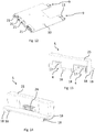
- the measuring circuit board 10 can be pushed or plugged into the upper part 3 from a side facing the carrier part 2 in a direction opposite to the arrow 20.
- the measuring plate 10 has a bearing structure 18 in the form of a linear projection, the upper part 3 having a counter-structure 19 corresponding to the bearing structure 18, into which the bearing structure 18 can be inserted along a straight line.
- the bearing structure 18 has a latching means 27 in the form of a projection, which with a portion of the counter structure 19 in the in the Fig. 11 The state shown interacts in a locking manner and unwanted movement of the measuring plate 10 from the in the Fig. 11 shown condition prevented.
- the Figures 10 and 11 show an arrangement in which the covers 23 are removed from the upper part 3.
- the first connecting device 4 and the second connecting device 9 can be electrically coupled in the present case to establish an electrical connection between the first component and the second component of the electronics by electrically coupling the first connecting device 4 to the second connecting device 9 when mechanically connecting the carrier part 2 and the upper part 3 , with the first connecting device 4 of the first component being electrically coupled to the second connecting device 9 of the second component when the carrier part 2 and the upper part 3 are connected to one another.
- the first connection device 4 of the first component electrically couples with the second connection device 9 of the second component, specifically the respective spring contact makes contact 11 of the second connecting device 9 each have a coupling surface 17 of the first connecting device 4, the contacting between the spring contact 11 and the respective coupling surfaces 17 taking place against the spring force of the respective spring contact 11.
- the measuring board 10 has several communication interfaces 21 for connecting the first component and the second component to further components of the electronics, in particular to further electronic components which are arranged outside of the switching device 1.
- the inventive design of the arrangement of the carrier part 2 and the upper part 3 of the switching strip with electronic components integrated in the arrangement enables particularly simple assembly.
- the immovable mounting of the first connecting device 4 and the second connecting device 9 prevents errors when connecting the components of the electronics.
- the carrier part 2 and the upper part 3 can be preassembled independently of one another, in particular fitted with the corresponding electronic components.
- the arrangement according to the invention thus enables a simple and, in particular, fault-free assembly of the carrier part 2 and upper part 3 or the switching device 1 as such with regard to the components of the electronics.
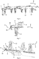
- FIGS. 19 and 20 show further embodiments of the invention, these differing from the first embodiment essentially in the design of the cover 23 and their mounting in the upper part 3.
- the Fig. 19 shows an embodiment in which the three covers 23 are pivotably mounted in the upper part 3 independently of one another.
- the respective cover 23 has a handle 24 in the form of a handle.
Landscapes
- Details Of Connecting Devices For Male And Female Coupling (AREA)
Claims (15)
- Agencement d'une partie de support (2), d'une partie supérieure (3) et d'un couvercle (23) d'un dispositif de commutation (1) comprenant des composants électroniques intégrés dans l'agencement, la partie de support (2) comportant au moins une paire de contacts (12) destinée à recevoir un fusible électrique ou un couteau de sectionnement, le fusible ou le couteau de sectionnement pouvant être inséré dans les contacts (12) de la partie de support (2) ou retiré des contacts (12) dans le but de commuter le dispositif de commutation (1), le couvercle (23) étant utilisé pour stocker le fusible électrique ou le couteau de sectionnement, le couvercle (23) étant monté dans la partie supérieure (3) de manière à être mobile entre une première position d'extrémité et une deuxième position d'extrémité, le fusible qui peut être monté dans le couvercle (23) ou le couteau de sectionnement qui peut être monté dans le couvercle (23) étant, dans la deuxième position d'extrémité, inséré dans les contacts (12) et le fusible électrique ou le couteau de sectionnement étant, dans la première position d'extrémité, sorti des contacts (12), la partie supérieure (3) pouvant être reliée mécaniquement à la partie de support (2), un premier composant de l'électronique étant monté dans la partie de support (2), caractérisé en ce qu'un deuxième composant de l'électronique est monté dans la partie supérieure (3), le premier composant comportant un premier dispositif de connexion (4), le premier dispositif de connexion (4) étant monté dans la partie de support (2), le deuxième composant comportant un deuxième dispositif de connexion (9), le deuxième dispositif de connexion (9) étant monté dans la partie supérieure (3), le premier dispositif de connexion (4) et le deuxième dispositif de connexion (9) pouvant être couplés électriquement et/ou optiquement l'un à l'autre pour établir une connexion électrique et/ou optique entre le premier composant et le deuxième composant par couplage électrique et/ou optique du premier dispositif de connexion (4) avec le deuxième dispositif de connexion (9) lors de la connexion mécanique de la partie de support (2) et de la partie supérieure (3).
- Agencement selon la revendication 1, la partie de support (2) et la partie supérieure (3) étant reliées l'une à l'autre, le premier dispositif de connexion (4) étant couplé électriquement et/ou optiquement au deuxième dispositif de connexion (9) indépendamment de la position de commutation du couvercle (23).
- Agencement selon la revendication 1 ou 2, la partie supérieure (3) pouvant être insérée dans la partie support (2), de préférence le long d'une ligne droite, le premier dispositif de connexion (4) étant monté de manière fixe dans la partie de support (2) perpendiculairement à la direction d'insertion et/ou le deuxième dispositif de connexion (9) étant monté de manière fixe dans la partie supérieure (3) perpendiculairement à la direction d'insertion.
- Agencement selon l'une des revendications 1 à 3, le premier dispositif de connexion (4) étant monté dans la partie de support (2) de manière fixe dans toutes les directions spatiales et/ou le deuxième dispositif de connexion (9) étant monté dans la partie supérieure (3) de manière fixe dans toutes les directions spatiales.
- Agencement selon l'une des revendications 1 à 4, le premier dispositif de connexion (4) du premier composant établissant un contact mécanique avec le deuxième dispositif de connexion (9) du deuxième composant lorsque la partie de support (2) et la partie supérieure (3) sont reliées l'une à l'autre.
- Agencement selon l'une des revendications 1 à 5, le premier dispositif de connexion (4) étant conçu comme un connecteur mâle et le deuxième dispositif de connexion (9) étant conçu comme un connecteur femelle correspondant au connecteur mâle ou le premier dispositif de connexion (4) étant conçu comme un connecteur femelle et le deuxième dispositif de connexion (9) étant conçu comme un connecteur mâle correspondant au connecteur femelle.
- Agencement selon l'une des revendications 1 à 6, le premier composant comportant une carte d'interface (5), la carte d'interface (5) comportant le premier dispositif de connexion (4), la carte d'interface (5) étant montée dans la partie de support (2).
- Agencement selon l'une des revendications 1 à 7, le premier dispositif de connexion (4), en particulier la carte d'interface (5), pouvant être poussé et/ou inséré dans la partie de support (2), en particulier pouvant être poussé et/ou inséré dans la partie de support (2) de manière encliquetable et/ou le deuxième dispositif de connexion (9) pouvant être poussé et/ou inséré dans la partie supérieure (3), en particulier pouvant être poussé et/ou inséré dans la partie supérieure (3) de manière encliquetable.
- Agencement selon l'une des revendications 1 à 8, le premier dispositif de connexion (4) et/ou le deuxième dispositif de connexion (9) comportant un contact à ressort (11).
- Agencement selon l'une des revendications 1 à 9, le deuxième composant comportant une carte de mesure (10), la carte de mesure (10) comportant le deuxième dispositif de connexion (9), la carte de mesure (10) étant montée dans la partie de support (2).
- Agencement selon l'une des revendications 1 à 10, le deuxième composant, en particulier la carte de mesure (10), comportant une interface de communication (21).
- Agencement selon l'une des revendications 1 à 11, le deuxième dispositif de connexion (9) comportant une surface de couplage (17) destinée à un couplage électrique et/ou optique avec le premier dispositif de connexion (4), la surface de couplage (17) étant disposée sur un côté de la partie supérieure (3) qui est dirigé vers la partie de support (2) et/ou le premier dispositif de connexion (4) comportant une surface de couplage (17) destinée à un couplage électrique et/ou optique avec le deuxième dispositif de connexion (9), la surface de couplage (17) étant disposée sur un côté de la partie de support (2) qui est dirigé vers la partie supérieure (3).
- Agencement selon l'une des revendications 1 à 12, le premier dispositif de connexion (4) et/ou le deuxième dispositif de connexion (9) étant disposés dans une région de bord de la partie de support (2) ou de la partie supérieure (3).
- Agencement selon l'une des revendications 1 à 13, le couvercle (23) étant monté de manière pivotante dans la partie supérieure (3), lorsque le fusible est monté dans le couvercle (23) ou lorsque le couteau de sectionnement est monté dans le couvercle (23), le fusible ou le couteau de sectionnement pouvant pivoter jusque dans les contacts (12) de la partie de support (2) ou hors des contacts (12) de la partie de support (2), ou le couvercle (23) pouvant coulisser linéairement dans la partie supérieure (3), le fusible ou le couteau de sectionnement pouvant être poussé dans les contacts (12) de la partie de support (2), ou retiré des contacts (12) de la partie de support (2), lorsque le fusible est monté dans le couvercle (23) ou lorsque le couteau de sectionnement est monté dans le couvercle (23).
- Agencement selon l'une des revendications 1 à 14, l'électronique, en particulier le premier composant et/ou le deuxième composant, comportant des éléments de mesure de tension et/ou de courant et/ou d'énergie et/ou de surveillance de fusible et/ou de surveillance de température, en particulier le premier composant comportant un transformateur de courant (8) et/ou une prise de tension (7) et/ou un câblage (6).
Priority Applications (1)
| Application Number | Priority Date | Filing Date | Title |
|---|---|---|---|
| PL19215122T PL3671786T3 (pl) | 2018-12-19 | 2019-12-11 | Układ części nośnej, części górnej i pokrywy urządzenia przełączającego ze zintegrowanymi z układem elementami składowymi układu elektronicznego |
Applications Claiming Priority (1)
| Application Number | Priority Date | Filing Date | Title |
|---|---|---|---|
| EP18214101.0A EP3671785A1 (fr) | 2018-12-19 | 2018-12-19 | Agencement d'une partie porteuse et d'une partie supérieure d'un dispositif de commutation doté des composants d'une électronique intégrés dans l'agencement |
Publications (2)
| Publication Number | Publication Date |
|---|---|
| EP3671786A1 EP3671786A1 (fr) | 2020-06-24 |
| EP3671786B1 true EP3671786B1 (fr) | 2021-03-31 |
Family
ID=64746200
Family Applications (2)
| Application Number | Title | Priority Date | Filing Date |
|---|---|---|---|
| EP18214101.0A Withdrawn EP3671785A1 (fr) | 2018-12-19 | 2018-12-19 | Agencement d'une partie porteuse et d'une partie supérieure d'un dispositif de commutation doté des composants d'une électronique intégrés dans l'agencement |
| EP19215122.3A Active EP3671786B1 (fr) | 2018-12-19 | 2019-12-11 | Agencement d'une pièce de support, d'une pièce supérieure et d'un couvercle d'un dispositif de commutation pourvu de composants d'une électronique intégrés dans ledit agencement |
Family Applications Before (1)
| Application Number | Title | Priority Date | Filing Date |
|---|---|---|---|
| EP18214101.0A Withdrawn EP3671785A1 (fr) | 2018-12-19 | 2018-12-19 | Agencement d'une partie porteuse et d'une partie supérieure d'un dispositif de commutation doté des composants d'une électronique intégrés dans l'agencement |
Country Status (3)
| Country | Link |
|---|---|
| EP (2) | EP3671785A1 (fr) |
| ES (1) | ES2877138T3 (fr) |
| PL (1) | PL3671786T3 (fr) |
Families Citing this family (5)
| Publication number | Priority date | Publication date | Assignee | Title |
|---|---|---|---|---|
| CN112563068B (zh) * | 2020-12-23 | 2025-07-15 | 上海良信电器股份有限公司 | 一种熔断式隔离开关 |
| PL4068329T3 (pl) * | 2021-03-31 | 2025-07-14 | Jean Müller GmbH Elektrotechnische Fabrik | Urządzenie do rozmieszczania na szynach zbiorczych zawierające przełącznik i element elektroniczny |
| EP4068323B1 (fr) * | 2021-03-31 | 2025-05-14 | Jean Müller GmbH Elektrotechnische Fabrik | Dispositif destiné à être agencé sur des barres de distribution, comprenant un dispositif de commutation et un module électronique |
| DE102022104394A1 (de) * | 2022-02-24 | 2023-08-24 | EBG innolab GmbH | Elektrische Schutzeinrichtung mit Messmodul |
| DE102022113758A1 (de) | 2022-05-31 | 2023-11-30 | EBG innolab GmbH | Elektrische Schutzeinrichtung mit Messmodul |
Family Cites Families (9)
| Publication number | Priority date | Publication date | Assignee | Title |
|---|---|---|---|---|
| DE3812504A1 (de) | 1988-04-15 | 1989-10-26 | Mueller Jean Ohg Elektrotech | Nh-sicherungslastschaltleiste |
| DE4438215C2 (de) | 1994-10-26 | 2000-11-02 | Efen Elektrotech Fab | NH-Sicherungs-Lasttrennschalter mit Sicherungsüberwachung |
| US6388563B1 (en) * | 1999-09-28 | 2002-05-14 | Rockwell Automation Technologies, Inc. | Modular relay with network communications |
| PL1993116T3 (pl) * | 2007-05-04 | 2011-01-31 | Efen Gmbh | Blok przełączników zasilania z bezpiecznikami |
| DE102008031335B4 (de) * | 2008-07-02 | 2012-03-22 | Eaton Industries Gmbh | Elektrisches Schutzschaltgerät mit Steuerelektronik |
| EP2546856B1 (fr) * | 2011-07-12 | 2016-05-11 | Jean Müller GmbH Elektrotechnische Fabrik | Baguette pour fusibles NH |
| EP2926360B1 (fr) * | 2012-11-29 | 2016-09-21 | Eaton Industries Manufacturing GmbH | Dispositif porte-fusible |
| BR112015013818A2 (pt) * | 2012-12-13 | 2017-07-11 | Efen Gmbh | transformador de corrente e seccionador de corte em carga com transformador de corrente |
| ES2875027T3 (es) * | 2014-08-13 | 2021-11-08 | Pronutec S A U | Base portafusibles |
-
2018
- 2018-12-19 EP EP18214101.0A patent/EP3671785A1/fr not_active Withdrawn
-
2019
- 2019-12-11 PL PL19215122T patent/PL3671786T3/pl unknown
- 2019-12-11 ES ES19215122T patent/ES2877138T3/es active Active
- 2019-12-11 EP EP19215122.3A patent/EP3671786B1/fr active Active
Non-Patent Citations (1)
| Title |
|---|
| None * |
Also Published As
| Publication number | Publication date |
|---|---|
| EP3671786A1 (fr) | 2020-06-24 |
| PL3671786T3 (pl) | 2021-11-22 |
| ES2877138T3 (es) | 2021-11-16 |
| EP3671785A1 (fr) | 2020-06-24 |
Similar Documents
| Publication | Publication Date | Title |
|---|---|---|
| EP3671786B1 (fr) | Agencement d'une pièce de support, d'une pièce supérieure et d'un couvercle d'un dispositif de commutation pourvu de composants d'une électronique intégrés dans ledit agencement | |
| EP2255369A1 (fr) | Borne serre-fil, en particulier borne sectionnable | |
| DE4217913A1 (de) | Kombinierte kabelschuh- und verbindungsanordnung fuer einen elektrischen schalter | |
| DE10045498A1 (de) | Elektrische Reihenklemme | |
| DE102008057754B4 (de) | Baueinheit aus mindestens zwei nebeneinander angeordneten Trennklemmen und mindestens zwei miteinander verbundenen Anschlusssteckern | |
| EP1912285B1 (fr) | Appareil électrique ou électronique | |
| EP0133152B1 (fr) | Dispositif pour la connexion de conducteurs auxiliaires à un appareil de commutation ou une combinaison d'appareils de commutation | |
| DE102006059384B4 (de) | Gerät mit einem Stromwandler zur Erfassung eines durch einen Stromleiter fließenden Stromes sowie Klemmen-/Stromwandler-Modul für ein derartiges Gerät | |
| DE102010052871B4 (de) | Reihenklemme | |
| DE10152347C1 (de) | Schaltgerät mit adaptiertem mehrphasigem Sammelschienensystem | |
| EP3561962A1 (fr) | Boîte de raccordement pour dispositifs électriques | |
| DE10039961C1 (de) | Elektrisches Gerät | |
| DE102011105157B4 (de) | Elektrisches Verbindungsmodul mit unterbrechbarem Stromkreis und Verfahren zum Erfassen einer Stromstärke | |
| DE69616265T2 (de) | Verzweigungsvorrichtung | |
| EP3142196B1 (fr) | Adaptateur de raccordement d'un systeme d'alimentation de barrettes de connexion et sa méthode d'arrangement | |
| DE19744827A1 (de) | Adapter für Stromsammelschienen | |
| EP4068323B1 (fr) | Dispositif destiné à être agencé sur des barres de distribution, comprenant un dispositif de commutation et un module électronique | |
| DE19616516C1 (de) | Trennadapter zum Einsatz in Steuerungssystemen | |
| EP2988312B1 (fr) | Module de fusible | |
| EP3671984B1 (fr) | Dispositif de commutation comprenant une pièce porteuse et comportant un composant d'une électronique disposé dans la pièce porteuse | |
| DE9312380U1 (de) | Federkraftklemme | |
| EP4068329B1 (fr) | Dispositif destiné à l'agencement sur barres de distribution comprenant un appareil de commutation et un composant électronique | |
| DE10003265A1 (de) | Stromkreisunterbrechereinrichtung | |
| DE29916001U1 (de) | Installationsschalter | |
| EP3590153A1 (fr) | Module à pont de câbles pour l'interconnexion flexible d'éléments de liaison |
Legal Events
| Date | Code | Title | Description |
|---|---|---|---|
| PUAI | Public reference made under article 153(3) epc to a published international application that has entered the european phase |
Free format text: ORIGINAL CODE: 0009012 |
|
| STAA | Information on the status of an ep patent application or granted ep patent |
Free format text: STATUS: REQUEST FOR EXAMINATION WAS MADE |
|
| 17P | Request for examination filed |
Effective date: 20200515 |
|
| AK | Designated contracting states |
Kind code of ref document: A1 Designated state(s): AL AT BE BG CH CY CZ DE DK EE ES FI FR GB GR HR HU IE IS IT LI LT LU LV MC MK MT NL NO PL PT RO RS SE SI SK SM TR |
|
| AX | Request for extension of the european patent |
Extension state: BA ME |
|
| GRAP | Despatch of communication of intention to grant a patent |
Free format text: ORIGINAL CODE: EPIDOSNIGR1 |
|
| STAA | Information on the status of an ep patent application or granted ep patent |
Free format text: STATUS: GRANT OF PATENT IS INTENDED |
|
| RIC1 | Information provided on ipc code assigned before grant |
Ipc: H01H 9/02 20060101AFI20200814BHEP Ipc: H01H 31/12 20060101ALN20200814BHEP Ipc: H01H 85/54 20060101ALN20200814BHEP |
|
| INTG | Intention to grant announced |
Effective date: 20200921 |
|
| GRAJ | Information related to disapproval of communication of intention to grant by the applicant or resumption of examination proceedings by the epo deleted |
Free format text: ORIGINAL CODE: EPIDOSDIGR1 |
|
| STAA | Information on the status of an ep patent application or granted ep patent |
Free format text: STATUS: REQUEST FOR EXAMINATION WAS MADE |
|
| INTC | Intention to grant announced (deleted) | ||
| GRAS | Grant fee paid |
Free format text: ORIGINAL CODE: EPIDOSNIGR3 |
|
| STAA | Information on the status of an ep patent application or granted ep patent |
Free format text: STATUS: GRANT OF PATENT IS INTENDED |
|
| GRAP | Despatch of communication of intention to grant a patent |
Free format text: ORIGINAL CODE: EPIDOSNIGR1 |
|
| RIC1 | Information provided on ipc code assigned before grant |
Ipc: H01H 85/54 20060101ALN20210111BHEP Ipc: H01H 9/02 20060101AFI20210111BHEP Ipc: H01H 31/12 20060101ALN20210111BHEP |
|
| INTG | Intention to grant announced |
Effective date: 20210129 |
|
| GRAA | (expected) grant |
Free format text: ORIGINAL CODE: 0009210 |
|
| STAA | Information on the status of an ep patent application or granted ep patent |
Free format text: STATUS: THE PATENT HAS BEEN GRANTED |
|
| AK | Designated contracting states |
Kind code of ref document: B1 Designated state(s): AL AT BE BG CH CY CZ DE DK EE ES FI FR GB GR HR HU IE IS IT LI LT LU LV MC MK MT NL NO PL PT RO RS SE SI SK SM TR |
|
| REG | Reference to a national code |
Ref country code: GB Ref legal event code: FG4D Free format text: NOT ENGLISH Ref country code: CH Ref legal event code: EP |
|
| REG | Reference to a national code |
Ref country code: DE Ref legal event code: R096 Ref document number: 502019001112 Country of ref document: DE Ref country code: AT Ref legal event code: REF Ref document number: 1377878 Country of ref document: AT Kind code of ref document: T Effective date: 20210415 |
|
| REG | Reference to a national code |
Ref country code: IE Ref legal event code: FG4D Free format text: LANGUAGE OF EP DOCUMENT: GERMAN |
|
| REG | Reference to a national code |
Ref country code: FI Ref legal event code: FGE |
|
| REG | Reference to a national code |
Ref country code: NL Ref legal event code: FP |
|
| REG | Reference to a national code |
Ref country code: LT Ref legal event code: MG9D |
|
| PG25 | Lapsed in a contracting state [announced via postgrant information from national office to epo] |
Ref country code: HR Free format text: LAPSE BECAUSE OF FAILURE TO SUBMIT A TRANSLATION OF THE DESCRIPTION OR TO PAY THE FEE WITHIN THE PRESCRIBED TIME-LIMIT Effective date: 20210331 Ref country code: NO Free format text: LAPSE BECAUSE OF FAILURE TO SUBMIT A TRANSLATION OF THE DESCRIPTION OR TO PAY THE FEE WITHIN THE PRESCRIBED TIME-LIMIT Effective date: 20210630 |
|
| PG25 | Lapsed in a contracting state [announced via postgrant information from national office to epo] |
Ref country code: RS Free format text: LAPSE BECAUSE OF FAILURE TO SUBMIT A TRANSLATION OF THE DESCRIPTION OR TO PAY THE FEE WITHIN THE PRESCRIBED TIME-LIMIT Effective date: 20210331 Ref country code: SE Free format text: LAPSE BECAUSE OF FAILURE TO SUBMIT A TRANSLATION OF THE DESCRIPTION OR TO PAY THE FEE WITHIN THE PRESCRIBED TIME-LIMIT Effective date: 20210331 Ref country code: LV Free format text: LAPSE BECAUSE OF FAILURE TO SUBMIT A TRANSLATION OF THE DESCRIPTION OR TO PAY THE FEE WITHIN THE PRESCRIBED TIME-LIMIT Effective date: 20210331 |
|
| PG25 | Lapsed in a contracting state [announced via postgrant information from national office to epo] |
Ref country code: CZ Free format text: LAPSE BECAUSE OF FAILURE TO SUBMIT A TRANSLATION OF THE DESCRIPTION OR TO PAY THE FEE WITHIN THE PRESCRIBED TIME-LIMIT Effective date: 20210331 Ref country code: EE Free format text: LAPSE BECAUSE OF FAILURE TO SUBMIT A TRANSLATION OF THE DESCRIPTION OR TO PAY THE FEE WITHIN THE PRESCRIBED TIME-LIMIT Effective date: 20210331 Ref country code: LT Free format text: LAPSE BECAUSE OF FAILURE TO SUBMIT A TRANSLATION OF THE DESCRIPTION OR TO PAY THE FEE WITHIN THE PRESCRIBED TIME-LIMIT Effective date: 20210331 Ref country code: SM Free format text: LAPSE BECAUSE OF FAILURE TO SUBMIT A TRANSLATION OF THE DESCRIPTION OR TO PAY THE FEE WITHIN THE PRESCRIBED TIME-LIMIT Effective date: 20210331 |
|
| REG | Reference to a national code |
Ref country code: ES Ref legal event code: FG2A Ref document number: 2877138 Country of ref document: ES Kind code of ref document: T3 Effective date: 20211116 |
|
| PG25 | Lapsed in a contracting state [announced via postgrant information from national office to epo] |
Ref country code: SK Free format text: LAPSE BECAUSE OF FAILURE TO SUBMIT A TRANSLATION OF THE DESCRIPTION OR TO PAY THE FEE WITHIN THE PRESCRIBED TIME-LIMIT Effective date: 20210331 Ref country code: RO Free format text: LAPSE BECAUSE OF FAILURE TO SUBMIT A TRANSLATION OF THE DESCRIPTION OR TO PAY THE FEE WITHIN THE PRESCRIBED TIME-LIMIT Effective date: 20210331 Ref country code: PT Free format text: LAPSE BECAUSE OF FAILURE TO SUBMIT A TRANSLATION OF THE DESCRIPTION OR TO PAY THE FEE WITHIN THE PRESCRIBED TIME-LIMIT Effective date: 20210802 Ref country code: IS Free format text: LAPSE BECAUSE OF FAILURE TO SUBMIT A TRANSLATION OF THE DESCRIPTION OR TO PAY THE FEE WITHIN THE PRESCRIBED TIME-LIMIT Effective date: 20210731 |
|
| REG | Reference to a national code |
Ref country code: DE Ref legal event code: R097 Ref document number: 502019001112 Country of ref document: DE |
|
| PG25 | Lapsed in a contracting state [announced via postgrant information from national office to epo] |
Ref country code: DK Free format text: LAPSE BECAUSE OF FAILURE TO SUBMIT A TRANSLATION OF THE DESCRIPTION OR TO PAY THE FEE WITHIN THE PRESCRIBED TIME-LIMIT Effective date: 20210331 Ref country code: AL Free format text: LAPSE BECAUSE OF FAILURE TO SUBMIT A TRANSLATION OF THE DESCRIPTION OR TO PAY THE FEE WITHIN THE PRESCRIBED TIME-LIMIT Effective date: 20210331 |
|
| PLBE | No opposition filed within time limit |
Free format text: ORIGINAL CODE: 0009261 |
|
| STAA | Information on the status of an ep patent application or granted ep patent |
Free format text: STATUS: NO OPPOSITION FILED WITHIN TIME LIMIT |
|
| 26N | No opposition filed |
Effective date: 20220104 |
|
| PG25 | Lapsed in a contracting state [announced via postgrant information from national office to epo] |
Ref country code: IS Free format text: LAPSE BECAUSE OF FAILURE TO SUBMIT A TRANSLATION OF THE DESCRIPTION OR TO PAY THE FEE WITHIN THE PRESCRIBED TIME-LIMIT Effective date: 20210731 |
|
| PG25 | Lapsed in a contracting state [announced via postgrant information from national office to epo] |
Ref country code: MC Free format text: LAPSE BECAUSE OF FAILURE TO SUBMIT A TRANSLATION OF THE DESCRIPTION OR TO PAY THE FEE WITHIN THE PRESCRIBED TIME-LIMIT Effective date: 20210331 Ref country code: IT Free format text: LAPSE BECAUSE OF FAILURE TO SUBMIT A TRANSLATION OF THE DESCRIPTION OR TO PAY THE FEE WITHIN THE PRESCRIBED TIME-LIMIT Effective date: 20210331 |
|
| REG | Reference to a national code |
Ref country code: BE Ref legal event code: MM Effective date: 20211231 |
|
| PG25 | Lapsed in a contracting state [announced via postgrant information from national office to epo] |
Ref country code: LU Free format text: LAPSE BECAUSE OF NON-PAYMENT OF DUE FEES Effective date: 20211211 Ref country code: IE Free format text: LAPSE BECAUSE OF NON-PAYMENT OF DUE FEES Effective date: 20211211 |
|
| PG25 | Lapsed in a contracting state [announced via postgrant information from national office to epo] |
Ref country code: FR Free format text: LAPSE BECAUSE OF NON-PAYMENT OF DUE FEES Effective date: 20211231 Ref country code: BE Free format text: LAPSE BECAUSE OF NON-PAYMENT OF DUE FEES Effective date: 20211231 |
|
| P01 | Opt-out of the competence of the unified patent court (upc) registered |
Effective date: 20230519 |
|
| PG25 | Lapsed in a contracting state [announced via postgrant information from national office to epo] |
Ref country code: CY Free format text: LAPSE BECAUSE OF FAILURE TO SUBMIT A TRANSLATION OF THE DESCRIPTION OR TO PAY THE FEE WITHIN THE PRESCRIBED TIME-LIMIT Effective date: 20210331 |
|
| PG25 | Lapsed in a contracting state [announced via postgrant information from national office to epo] |
Ref country code: HU Free format text: LAPSE BECAUSE OF FAILURE TO SUBMIT A TRANSLATION OF THE DESCRIPTION OR TO PAY THE FEE WITHIN THE PRESCRIBED TIME-LIMIT; INVALID AB INITIO Effective date: 20191211 Ref country code: GR Free format text: LAPSE BECAUSE OF FAILURE TO SUBMIT A TRANSLATION OF THE DESCRIPTION OR TO PAY THE FEE WITHIN THE PRESCRIBED TIME-LIMIT Effective date: 20210331 |
|
| PG25 | Lapsed in a contracting state [announced via postgrant information from national office to epo] |
Ref country code: MK Free format text: LAPSE BECAUSE OF FAILURE TO SUBMIT A TRANSLATION OF THE DESCRIPTION OR TO PAY THE FEE WITHIN THE PRESCRIBED TIME-LIMIT Effective date: 20210331 |
|
| GBPC | Gb: european patent ceased through non-payment of renewal fee |
Effective date: 20231211 |
|
| PG25 | Lapsed in a contracting state [announced via postgrant information from national office to epo] |
Ref country code: MT Free format text: LAPSE BECAUSE OF FAILURE TO SUBMIT A TRANSLATION OF THE DESCRIPTION OR TO PAY THE FEE WITHIN THE PRESCRIBED TIME-LIMIT Effective date: 20210331 |
|
| PG25 | Lapsed in a contracting state [announced via postgrant information from national office to epo] |
Ref country code: GB Free format text: LAPSE BECAUSE OF NON-PAYMENT OF DUE FEES Effective date: 20231211 |
|
| PG25 | Lapsed in a contracting state [announced via postgrant information from national office to epo] |
Ref country code: GB Free format text: LAPSE BECAUSE OF NON-PAYMENT OF DUE FEES Effective date: 20231211 |
|
| REG | Reference to a national code |
Ref country code: CH Ref legal event code: U11 Free format text: ST27 STATUS EVENT CODE: U-0-0-U10-U11 (AS PROVIDED BY THE NATIONAL OFFICE) Effective date: 20260101 |
|
| PGFP | Annual fee paid to national office [announced via postgrant information from national office to epo] |
Ref country code: AT Payment date: 20251222 Year of fee payment: 7 |
|
| PGFP | Annual fee paid to national office [announced via postgrant information from national office to epo] |
Ref country code: FI Payment date: 20251223 Year of fee payment: 7 |
|
| PGFP | Annual fee paid to national office [announced via postgrant information from national office to epo] |
Ref country code: NL Payment date: 20251219 Year of fee payment: 7 |
|
| PGFP | Annual fee paid to national office [announced via postgrant information from national office to epo] |
Ref country code: TR Payment date: 20251203 Year of fee payment: 7 |
|
| PGFP | Annual fee paid to national office [announced via postgrant information from national office to epo] |
Ref country code: BG Payment date: 20251219 Year of fee payment: 7 Ref country code: PL Payment date: 20251201 Year of fee payment: 7 |
|
| PGFP | Annual fee paid to national office [announced via postgrant information from national office to epo] |
Ref country code: ES Payment date: 20260130 Year of fee payment: 7 |
|
| PGFP | Annual fee paid to national office [announced via postgrant information from national office to epo] |
Ref country code: DE Payment date: 20251218 Year of fee payment: 7 |
|
| PGFP | Annual fee paid to national office [announced via postgrant information from national office to epo] |
Ref country code: CH Payment date: 20260101 Year of fee payment: 7 |