EP3671994A1 - Installation de commutation moyenne ou haute tension - Google Patents
Installation de commutation moyenne ou haute tension Download PDFInfo
- Publication number
- EP3671994A1 EP3671994A1 EP18215496.3A EP18215496A EP3671994A1 EP 3671994 A1 EP3671994 A1 EP 3671994A1 EP 18215496 A EP18215496 A EP 18215496A EP 3671994 A1 EP3671994 A1 EP 3671994A1
- Authority
- EP
- European Patent Office
- Prior art keywords
- current transformer
- cable
- high voltage
- medium
- hole
- Prior art date
- Legal status (The legal status is an assumption and is not a legal conclusion. Google has not performed a legal analysis and makes no representation as to the accuracy of the status listed.)
- Withdrawn
Links
- 239000006260 foam Substances 0.000 claims abstract description 61
- 238000004382 potting Methods 0.000 claims abstract description 56
- 150000001875 compounds Chemical class 0.000 claims abstract description 52
- 238000005520 cutting process Methods 0.000 claims description 11
- 238000000034 method Methods 0.000 claims description 10
- 230000001419 dependent effect Effects 0.000 claims description 2
- 239000000463 material Substances 0.000 description 9
- 238000007789 sealing Methods 0.000 description 6
- 239000007788 liquid Substances 0.000 description 5
- 238000001816 cooling Methods 0.000 description 4
- 238000003780 insertion Methods 0.000 description 4
- 230000037431 insertion Effects 0.000 description 4
- 239000012530 fluid Substances 0.000 description 3
- 239000007787 solid Substances 0.000 description 3
- 238000005429 filling process Methods 0.000 description 2
- 239000003292 glue Substances 0.000 description 2
- 238000004519 manufacturing process Methods 0.000 description 2
- 239000004593 Epoxy Substances 0.000 description 1
- 229920005830 Polyurethane Foam Polymers 0.000 description 1
- 229910000831 Steel Inorganic materials 0.000 description 1
- 238000004026 adhesive bonding Methods 0.000 description 1
- 239000004020 conductor Substances 0.000 description 1
- 230000009969 flowable effect Effects 0.000 description 1
- 238000009434 installation Methods 0.000 description 1
- 238000009413 insulation Methods 0.000 description 1
- 238000000465 moulding Methods 0.000 description 1
- 229920001296 polysiloxane Polymers 0.000 description 1
- 229920002635 polyurethane Polymers 0.000 description 1
- 239000004814 polyurethane Substances 0.000 description 1
- 239000011496 polyurethane foam Substances 0.000 description 1
- 230000009467 reduction Effects 0.000 description 1
- 239000011493 spray foam Substances 0.000 description 1
- 239000010959 steel Substances 0.000 description 1
- 239000012815 thermoplastic material Substances 0.000 description 1
- 238000009423 ventilation Methods 0.000 description 1
- XLYOFNOQVPJJNP-UHFFFAOYSA-N water Substances O XLYOFNOQVPJJNP-UHFFFAOYSA-N 0.000 description 1
Images


Classifications
-
- H—ELECTRICITY
- H02—GENERATION; CONVERSION OR DISTRIBUTION OF ELECTRIC POWER
- H02B—BOARDS, SUBSTATIONS OR SWITCHING ARRANGEMENTS FOR THE SUPPLY OR DISTRIBUTION OF ELECTRIC POWER
- H02B13/00—Arrangement of switchgear in which switches are enclosed in, or structurally associated with, a casing, e.g. cubicle
- H02B13/02—Arrangement of switchgear in which switches are enclosed in, or structurally associated with, a casing, e.g. cubicle with metal casing
- H02B13/035—Gas-insulated switchgear
- H02B13/0356—Mounting of monitoring devices, e.g. current transformers
-
- H—ELECTRICITY
- H02—GENERATION; CONVERSION OR DISTRIBUTION OF ELECTRIC POWER
- H02B—BOARDS, SUBSTATIONS OR SWITCHING ARRANGEMENTS FOR THE SUPPLY OR DISTRIBUTION OF ELECTRIC POWER
- H02B13/00—Arrangement of switchgear in which switches are enclosed in, or structurally associated with, a casing, e.g. cubicle
- H02B13/02—Arrangement of switchgear in which switches are enclosed in, or structurally associated with, a casing, e.g. cubicle with metal casing
- H02B13/035—Gas-insulated switchgear
- H02B13/0358—Connections to in or out conductors
Definitions
- the present invention relates to a medium or high voltage switchgear panel, a plate for a medium or high voltage switchgear panel, and a method of fixing components of a medium or high voltage switchgear panel.
- a switchgear can be referred to as a switchgear unit or switchgear panel.
- switchgear panel For example, several components of a switchgear panel are fixed individually to a frame of the switchgear panel. A gap exists between these components, for example between a cable and a current transformer (CT) around this cable. This gap exists because the end of the cable with its connector has a larger diameter than the cable itself, and this end has to be passed through the opening of the CT during the assembly of the switchgear.
- CT current transformer
- a medium voltage or high voltage switchgear panel comprising:
- the hole through a current transformer of the at least one current transformer has two areas at two opposing sides of the current transformer.
- the two areas are formed between the current transformer and the cable at positions of the two opposing sides of the current transformer, and wherein at least one plate covers at least one area of the two areas.
- one or more plates can cover one or both of the gaps around the cable at the positions where the cable enters and exits the current transformer.
- one side of a current transformer can have a plate or plates that covers the gap between the cable and the hole, or both sides of the current transformer can have a plate or plates that covers the gap between the cable and the hole at each side of the current transformer.
- the foam or potting compound is contained at the correct position, and the plates facilitate application or insertion of the foam or potting compound, ensuring that the foam or potting compound is located as required. Additionally, the plate(s) can enable a relatively flowable foam or potting compound to be used, that can be stopped from flowing outside of where it is required by the plate(s).
- a first area of the two areas is covered by at least two plates.
- a first one of the at least two plates covers a first part of the first area and a second one of the at least two plates covers a second part of the first area.
- the first one of the at least two plates covers half of the first area and the second one of the at least two plates covers the remaining half of the first area.
- the two plates can be arcuately shaped. Being half discs with a centre circular part missing that fits around the cable and an outer circular part that matches the hole through the current transformer. By making the plates in this manner, they can be identically formed providing for ease of manufacture.
- the at least one plate comprises at least a part of a ring that extends at least partially into the hole through the current transformer.
- the plate can have a portion shaped to an outside of the current transformer, for example being flat, that fits up against the current transformer around the cable and covering the space around the cable between the cable and the current transformer - there can then be more than one plate that act together to completely cover this gap between the cable and the current transformer and the cable formed by the hole through the current transformer.
- the plate has a partial ring shaped portion, for example a half circle in form in the plane of the plate but that also has a length that can be perpendicular to the flat portion of the plate. This partial ring then is inserted into the hole, when the plate is fitted around the cable to cover the hole, and helps to secure the plate in position.
- the at least part of the ring comprises an outward facing flexible or elastic seal that forms a seal with at least part of the surface of the current transformer formed by the hole.
- the at least part of the ring comprises an inward facing flexible or elastic seal that forms a seal with at least part of the surface of the cable.
- the seal contains the foam or potting compound in the space between the cable and the current transformer at the position of the hole and stops this from flowing elsewhere.
- a second area of the two areas is covered by at least two plates.
- a first one of the at least two plates covers a first part of the first area and a second one of the at least two plates covers a second part of the first area.
- the second area is situated vertically above the first area.
- At least one of the two plates that cover the second area has at least one hole through which the foam or potting compound can be, or was, inserted to fill the volume.
- At least one hollow tube is located within the foam or potting compound, and forms at least one conduit through the foam or potting compound.
- a hollow tube that is open at both ends is provided through the foam or potting compound.
- fluid such as air, or other fluids such as a specific gas or a liquid can flow through the hollow tube and provide for cooling of the foam or potting compound.
- the at least one hollow tube is integrated into one or more of the at least one plate.
- At least one cutting wire is located within the foam or potting compound that fills the at least one hole, thereby enabling the foam or potting compound to be cut.
- both ends of each wire of the at least one the cutting wire protrude out of the same end of the hole through a current transformer.
- an efficient and convenient means is provided to cut the foam or potting compound during disassembly, for example by pulling on the ends of the wire that then cuts through the foam or potting compound.
- the at least one current transformer comprises a plurality of current transformers. At least one volume between facing sides of adjacent current transformers is at least partially filled with a foam or potting compound. In this manner, the current transformers can be fixed relative to one another in a convenient manner, reducing the requirement for normal fixing and thereby reducing costs and assembly times.
- a plate for a medium or high voltage switchgear panel is configured to cover at least one of at least two areas at opposing sides of a current transformer of a medium or high voltage switchgear.
- the at least two areas are formed when a cable passes through a hole through the current transformer.
- the two areas are formed between the current transformer and the cable at the positions of the two opposing sides of the current transformer.
- a method of fixing components of a medium or high voltage switchgear panel comprises at least one cable and at least one current transformer. Each cable of the at least one cable passes through at least one hole through the at least one current transformer. One cable of the at least one cable passes through the hole of a corresponding one current transformer of the at least one current transformer.
- the method comprises: filling with a foam or potting compound at least one volume between a surface of each cable of the at least one cable and a surface through each corresponding current transformer formed by the hole.
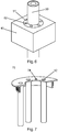
- Figs. 1-7 show detailed examples of a MV or HV switchgear panel, with foam or potting compound being used to fix certain components. Means are provided to aid disassembly, and to aid cooling.
- the figures show a medium voltage (MV) or high voltage (HV) switchgear panel 1.
- the MV or HV switchgear panel comprises at least one cable 30, and at least one current transformer 40. Each cable of the at least one cable passes through at least one hole through the at least one current transformer. One cable of the at least one cable passes through the hole of a corresponding one current transformer of the at least one current transformer.
- At least one volume 50 between a surface of each cable of the at least one cable and a surface through each corresponding current transformer formed by the hole is at least partially filled with a foam or potting compound.
- the at least one volume 50 is filled with the foam or potting compound.
- the hole through a current transformer of the at least one current transformer has two areas at two opposing sides of the current transformer.
- the two areas are formed between the current transformer and the cable at positions of the two opposing sides of the current transformer.
- At least one plate 70 covers at least one area of the two areas.
- a single flexible plate with a centre circular hole and a slit from this centre hole extending to the outside can be twisted open and placed around the cable at the entrance to the current transformer.
- several separate plates can operate together and be placed at the entrance to the current transformer around the cable to close the area between the cable and the current transformer.
- a first area of the two areas is covered by at least two plates 70.
- a first one of the at least two plates covers a first part of the first area and a second one of the at least two plates covers a second part of the first area.
- two plates can operate together to cover the area, with one plate covering half of the area and the other plate covering the other half.
- the first one of the at least two plates covers half of the first area and the second one of the at least two plates covers the other half of the first area.
- the at least one plate 70 comprises at least a part of a ring 72 that extends at least partially into the hole through the current transformer.
- the at least part of the ring 72 comprises an outward facing flexible or elastic seal 73 that forms a seal with at least part of the surface of the current transformer formed by the hole.
- the at least part of the ring 72 comprises an inward facing flexible or elastic seal 73 that forms a seal with at least part of the surface of the cable.
- a second area of the two areas is covered by at least two plates 70.
- a first one of the at least two plates covers a first part of the first area and a second one of the at least two plates covers a second part of the first area.
- the second area is situated vertically above the first area.
- At least one of the two plates that cover the second area has at least one hole 74 through which the foam or potting compound can be, or was, inserted to fill the volume 50.
- at least one hollow tube 52 is located within the foam or potting compound, and forms at least one conduit through the foam or potting compound.
- the at least one hollow tube is integrated into one or more of the at least one plate.
- At least one cutting wire 90 is located within the foam or potting compound that fills the at least one hole, thereby enabling the foam or potting compound to be cut for disassembly in case of need.
- both ends of each wire of the at least one the cutting wire 90 protrude out of the same end of the hole through a current transformer.
- the at least one current transformer comprises a plurality of current transformers, and wherein at least one volume 60 between facing sides of adjacent current transformers is at least partially filled with a foam or potting compound.
- the at least one volume 60 is filled with the foam or potting compound.
- at least one plate 80 covers at least one area between the adjacent current transformers.
- a plate 80 can cover the bottom area between two adjacent current transformers and another plate 80 can cover the front area between those two adjacent current transformers. In an example, another plate can cover the top area between those two adjacent current transformers. In an example, a single plate 80 can be bent to cover the bottom and front areas between two adjacent current transformers. In an example, a single plate 80 can be bent to cover the bottom, front and top areas between two adjacent current transformers. In an example, the plate 80 has two structures perpendicular to a plane of the plate 80 that extend into the gap between the two adjacent current transformers.
- One structure extends subtantailly parallel to a side of a first of the two current transformers and one structure extends substantially parallel to a side of a second of the two current transformers that faces the side of the first current transformer.
- the two perpendicular structures have a flexible or elastic seal that faces towards the side of the current transformer to form a seal with the side of the current transformer.
- the figures also show a plate 70 for a medium or high voltage switchgear panel.
- At least one plate is configured to cover at least one of at least two areas at opposing sides of a current transformer 40 of a medium or high voltage switchgear.
- the at least two areas are formed when a cable 30 passes through a hole through the current transformer.
- the two areas are formed between the current transformer and the cable at the positions of the two opposing sides of the current transformer.
- a first one at least two plates is configured to cover a first part of a first area of the two areas and a second one of the at least two plates is configured to cover a second part of the first area.
- the first one of the at least two plates is configured to cover half of the first area and the second one of the at least two plates is configured to cover half of the first area.
- the at least one plate 70 comprises at least a part of a ring 72 that is configured to extend at least partially into the hole through the current transformer.
- the at least part of the ring 72 comprises an outward facing flexible or elastic seal 73 that is configured to form a seal with at least part of the surface of the current transformer formed by the hole.
- the at least one plate comprises at least one hole, where one or more of the at least one hole is configured to enable foam or potting compound to be injected through one or more hole.
- the at least one plate comprises at least one hollow tube integrated into the at least one plate, wherein the at least one tube is configured to form a conduit through the hole through the current transformer.
- a method of fixing components of a medium or high voltage switchgear panel 1 was used in assembly of the medium or high voltage switchgear.
- the medium or high voltage switchgear panel comprises at least one cable 30 and at least one current transformer 40.
- Each cable of the at least one cable passes through at least one hole through the at least one current transformer.
- One cable of the at least one cable passes through the hole of a corresponding one current transformer of the at least one current transformer.
- the method comprises filling with a foam or potting compound at least one volume 50 between a surface of each cable of the at least one cable and a surface through each corresponding current transformer formed by the hole.
- FIG. 1 shows as an example a switchgear panel 1 with a compartment 10.
- a current transforemer (CT) 40 is installed around each cable. All CTs are fixed onto a bar of the frame 20. In this example installation is at the rear side of the panel.
- the cables 30 have a connector at their upper end for insertion into the compartment 10. The diameter of this connector end is larger than the regular diameter of the cable at the location of the CT.
- the inner opening of the CT 40 is larger than the regular diameter of the cable. Therefore, spaces 50 are created between each cable and its CT. Furthermore, spaces 60 are created between the neighbored CTs.
- the spaces 50 and / or 60 are at least partly filled with constructive foam or potting compound to increase the mechanical stiffness of the fixation of the cables 30.
- Other means of fixation of the cable, that are normally used, can then be reduced or omitted to achieve the required stiffness for withstanding the peak forces under short circuit conditions.
- the constructive foam or spray foam or polyurethane foam or potting compound will fill most of the space 50, 60.
- the foam or potting compound will glue to the cables and the CTs and it will become a solid part that is able to bear mechanical forces.
- the surfaces of the spaces 50, 60 can be wetted with water in order to support the curing process of the foam or potting compound.
- the spaces 50, 60 are covered with plates 70, 80.
- These plates can for example be made of thermoplastic material with features for a mechanical latching at the desired location during the filling with the constructive foam or potting compound.
- Each plate 70 covers one half of the opening of the space 50, so that the plates 70 can be assembled around the cable 30. After the filling, the plates are also fixed by gluing to the constructive foam.
- the plates can be in other forms, such as each covering a third or quarter of the space 50, and indeed a flexible single plate with a slit from a centre hole to the edge can be twisted out of shape and positioned around a cable and then put back into a planar shape.
- Fig. 3 shows in a sectional view the areas around the CTs 40. After application of constructive foam or potting compound to the spaces 50, 60, a solid block is created, including the cables 30, the CTs 40 and the frame 20.
- Fig. 4 shows an advantageous embodiment of the plate 70. It has the general shape of a semicircle so that two of these plates can be assembled around the cable 30. Plate 70 consists of a flat plate 71 to cover the space 50 and to rest on the CT 40. It further comprises a ring 72 for insertion and adjustment in the inner opening of the CT 40. In the embodiment shown, the ring 72 is equipped with a flexible or elastic sealing 73 to make sure that no filling material flows through the gap between the plate 70 and the CT 40.
- the flexibility of the sealing can compensate for mechanical tolerances.
- Another sealing could also be added at the inner opening of plate 70 to seal the plate 70 against the cable 30.
- a rigid plate 70 with one or more elastic sealings 73 can be generated in a 2-component moulding process, with an appropriate process described for example in EP2461338B1 .
- the plate 70 comprises one or more openings 74 so that each space 50 has one or more openings for the insertion of the filling material and one or more openings for a controlled overrun of the filling material in case of need.
- the plate 80 can be designed accordingly, having the same features as the plate 70.
- potting materials like silicone, epoxy, polyurethane (not as a foam here) or alike can be practically liquid when they are filled in the openings 74, and they will cure and glue to the involved surfaces.
- the plates now form a fluid tight seal and there is no flow out of the required region. The result will be a mechanically very solid structure. Therefore, openings 74 can be positioned in plates on the top end of the cavities in case of using a practically liquid potting material.
- the foam can be cut with a dedicated tool like an especially formed knife. It is also possible to drill two holes through the foam and then to pull a thin steel wire through a section of the foam for cutting this section, etc. Plates 70 can be mechanically removed.
- a dedicated tool like an especially formed knife.
- Plates 70 can be mechanically removed.
- four cutting wires 90 are included in the foam or potting compound. When both ends of the wire are pulled from below, one fourth of the foam or potting compound is cut.
- one or more tubes can be placed in this region. These tubes are generally empty, so that air can flow through the tubes and transport heat to the outside. This transport of heat can work more efficiently when the cable, CT and tubes are oriented vertically. In case the orientation of the cable and the CT has to be horizontally due to other constraints, the tubes can at least be placed inclined, using the available space, to allow for some natural ventilation. Additionally, additional means for the transfer of heat can be used with the tubes, such as metallic inserts, heat pipes and liquid cooling. From the manufacturing point of view, the tubes can be separate parts that are held in position by dedicated openings in the cover plates 70, 80 during the filling process. Alternatively, the tubes 52 can be integrated into the cover plates, as shown in Fig. 7 .
Landscapes
- Engineering & Computer Science (AREA)
- Power Engineering (AREA)
- Patch Boards (AREA)
Priority Applications (1)
| Application Number | Priority Date | Filing Date | Title |
|---|---|---|---|
| EP18215496.3A EP3671994A1 (fr) | 2018-12-21 | 2018-12-21 | Installation de commutation moyenne ou haute tension |
Applications Claiming Priority (1)
| Application Number | Priority Date | Filing Date | Title |
|---|---|---|---|
| EP18215496.3A EP3671994A1 (fr) | 2018-12-21 | 2018-12-21 | Installation de commutation moyenne ou haute tension |
Publications (1)
| Publication Number | Publication Date |
|---|---|
| EP3671994A1 true EP3671994A1 (fr) | 2020-06-24 |
Family
ID=64949073
Family Applications (1)
| Application Number | Title | Priority Date | Filing Date |
|---|---|---|---|
| EP18215496.3A Withdrawn EP3671994A1 (fr) | 2018-12-21 | 2018-12-21 | Installation de commutation moyenne ou haute tension |
Country Status (1)
| Country | Link |
|---|---|
| EP (1) | EP3671994A1 (fr) |
Citations (5)
| Publication number | Priority date | Publication date | Assignee | Title |
|---|---|---|---|---|
| US2920297A (en) * | 1955-04-28 | 1960-01-05 | Ite Circuit Breaker Ltd | Current transformer |
| DE975904C (de) * | 1952-02-13 | 1962-11-29 | Friedrich Dr-Ing E H Raupach | Einleiterstromwandler mit auf eine Sammelschiene aufsteckbarem Gehaeuse |
| US20080174320A1 (en) * | 2007-01-24 | 2008-07-24 | Smith James E | Partial discharge sensor and partial discharge monitoring system utilizing current sensors |
| EP2461338B1 (fr) | 2010-12-03 | 2014-05-07 | ABB Technology AG | Agencement de disjoncteur pour application de moyenne tension à haute tension |
| US8816527B1 (en) * | 2013-03-27 | 2014-08-26 | Smart Wire Grid, Inc. | Phase balancing of power transmission system |
-
2018
- 2018-12-21 EP EP18215496.3A patent/EP3671994A1/fr not_active Withdrawn
Patent Citations (5)
| Publication number | Priority date | Publication date | Assignee | Title |
|---|---|---|---|---|
| DE975904C (de) * | 1952-02-13 | 1962-11-29 | Friedrich Dr-Ing E H Raupach | Einleiterstromwandler mit auf eine Sammelschiene aufsteckbarem Gehaeuse |
| US2920297A (en) * | 1955-04-28 | 1960-01-05 | Ite Circuit Breaker Ltd | Current transformer |
| US20080174320A1 (en) * | 2007-01-24 | 2008-07-24 | Smith James E | Partial discharge sensor and partial discharge monitoring system utilizing current sensors |
| EP2461338B1 (fr) | 2010-12-03 | 2014-05-07 | ABB Technology AG | Agencement de disjoncteur pour application de moyenne tension à haute tension |
| US8816527B1 (en) * | 2013-03-27 | 2014-08-26 | Smart Wire Grid, Inc. | Phase balancing of power transmission system |
Similar Documents
| Publication | Publication Date | Title |
|---|---|---|
| RU2201026C2 (ru) | Устройство и способ для удержания и направления удлиненных объектов | |
| EP2273295A1 (fr) | Système de fixation d'armoire de réseau | |
| US20220393538A1 (en) | Stator for electric machine, electric machine, and motor vehicle | |
| US11605995B2 (en) | Spacer to control oil flow in stator winding | |
| CN109565166B (zh) | 线缆穿壁装置及套件 | |
| US9520703B2 (en) | Electrical busway splice connector | |
| US2908744A (en) | Cable splice cover | |
| US8791367B2 (en) | Network cabinet fitting system | |
| RU2202848C2 (ru) | Концевая плита | |
| CN102224651A (zh) | 用于密封供管、管道或缆线延伸穿过的圆管状开口的组件 | |
| EP3671994A1 (fr) | Installation de commutation moyenne ou haute tension | |
| US20220029492A1 (en) | Isolating ring, stator and electric machine | |
| EP3763574A1 (fr) | Structure de routage de faisceau de câbles pour panneau, module de faisceau et procédé de routage de faisceau de câbles pour panneau | |
| EP2538508B1 (fr) | Dispositif d'étanchéité pour filaments traversants | |
| EP3869525B1 (fr) | Douille comportant une tête électroconductrice montée sur un noyau de condensateur | |
| TWI405224B (zh) | 三相電流變流器及配備該電流變流器之電廠 | |
| EP1965477A1 (fr) | Système modulaire pour former des joints de connexion préassemblés en forme de coudes, de T, de X ou flexibles pour sections préfabriquées de conduits électriques | |
| CN112490981A (zh) | 线束过壁结构及其安装方法 | |
| CN106314313A (zh) | 用于接收电缆线束的装置 | |
| US4866216A (en) | Method and apparatus for sealing electrical busbar corner | |
| EP3522339A1 (fr) | Séparateur pour enroulements | |
| CN110573384A (zh) | 用于交通工具的套管中的线路元件的容纳装置 | |
| CN100407528C (zh) | 用于预制电导体的壳体 | |
| EP3489566B1 (fr) | Ensemble goulotte pour conduites de fluides | |
| JP7824497B1 (ja) | ワイヤハーネスおよびロボット |
Legal Events
| Date | Code | Title | Description |
|---|---|---|---|
| PUAI | Public reference made under article 153(3) epc to a published international application that has entered the european phase |
Free format text: ORIGINAL CODE: 0009012 |
|
| STAA | Information on the status of an ep patent application or granted ep patent |
Free format text: STATUS: THE APPLICATION HAS BEEN PUBLISHED |
|
| AK | Designated contracting states |
Kind code of ref document: A1 Designated state(s): AL AT BE BG CH CY CZ DE DK EE ES FI FR GB GR HR HU IE IS IT LI LT LU LV MC MK MT NL NO PL PT RO RS SE SI SK SM TR |
|
| AX | Request for extension of the european patent |
Extension state: BA ME |
|
| STAA | Information on the status of an ep patent application or granted ep patent |
Free format text: STATUS: THE APPLICATION IS DEEMED TO BE WITHDRAWN |
|
| 18D | Application deemed to be withdrawn |
Effective date: 20210112 |