EP3672003A1 - Use of a feed through for casting into a wall element - Google Patents
Use of a feed through for casting into a wall element Download PDFInfo
- Publication number
- EP3672003A1 EP3672003A1 EP18213036.9A EP18213036A EP3672003A1 EP 3672003 A1 EP3672003 A1 EP 3672003A1 EP 18213036 A EP18213036 A EP 18213036A EP 3672003 A1 EP3672003 A1 EP 3672003A1
- Authority
- EP
- European Patent Office
- Prior art keywords
- section
- everting
- protective tube
- bushing
- use according
- Prior art date
- Legal status (The legal status is an assumption and is not a legal conclusion. Google has not performed a legal analysis and makes no representation as to the accuracy of the status listed.)
- Granted
Links
Images

Classifications
-
- H—ELECTRICITY
- H02—GENERATION; CONVERSION OR DISTRIBUTION OF ELECTRIC POWER
- H02G—INSTALLATION OF ELECTRIC CABLES OR LINES, OR OF COMBINED OPTICAL AND ELECTRIC CABLES OR LINES
- H02G3/00—Installations of electric cables or lines or protective tubing therefor in or on buildings, equivalent structures or vehicles
- H02G3/22—Installations of cables or lines through walls, floors or ceilings, e.g. into buildings
-
- F—MECHANICAL ENGINEERING; LIGHTING; HEATING; WEAPONS; BLASTING
- F16—ENGINEERING ELEMENTS AND UNITS; GENERAL MEASURES FOR PRODUCING AND MAINTAINING EFFECTIVE FUNCTIONING OF MACHINES OR INSTALLATIONS; THERMAL INSULATION IN GENERAL
- F16L—PIPES; JOINTS OR FITTINGS FOR PIPES; SUPPORTS FOR PIPES, CABLES OR PROTECTIVE TUBING; MEANS FOR THERMAL INSULATION IN GENERAL
- F16L5/00—Devices for use where pipes, cables or protective tubing pass through walls or partitions
- F16L5/02—Sealing
Definitions
- the present invention relates to a bushing for pouring into a wall element and passing a line through it.
- the implementation is usually poured in during the manufacture of the wall element, for example when it is poured from concrete.
- the bushing can be mounted on a formwork, after which it sits integrated in the concrete wall. It keeps a through opening between the opposite side surfaces of the wall free, through which a cable or other line can then be laid.
- the present invention is based on the technical problem of specifying a particularly advantageous use or implementation as the object of use.
- the bushing has an everted section which is turned over during the pouring in of the bushing and is turned out after the pouring in, a protective tube then being inserted into the everted out section.
- the actual line is laid in the protective tube, for example the cable in the example at the beginning.
- step i) This implementation or the procedure according to steps i.) - iii.) According to claim 1 can be advantageous, for example, insofar as the implementation in the inserted state (step i) is compact, which, for example, can simplify the shuttering. Installation in wall elements with a comparatively small thickness is also possible. The everted section can then be easily accessible, which can simplify the insertion of the protective tube or any fastening thereof.
- the protective tube is typically in a trench or under otherwise confined conditions (e.g. several protective tubes side by side or one above the other, see below) to the wall element, which is why good and easy handling is advantageous.
- the protrusion of the everting section is also a comparatively simple process; for example, a connecting sleeve or the like does not have to be laboriously installed on the cast-in bushing.
- This can also be advantageous, for example, in terms of reducing the number of connection points; especially when working on the ground, each connection point increases the risk of possible contamination during assembly and thus possible later leakage.
- the protective tube can, for example, have an outer diameter of at least 50 mm, 70 mm, 90 mm or 100 mm, with possible (independent) upper limits at z. B. at most 300 mm, 250 mm, 200 mm or 180 mm (increasingly preferred in each case in the order of mention).
- the everted section has a suitable inner diameter, it can also be slightly stretched when the protective tube is inserted. In the diameter range mentioned, on the one hand, the protrusion may well be possible (becomes increasingly difficult with smaller diameters), on the other hand, the forces caused by the weight of the protective tube are not yet too great.
- the everted section is preferably attached to the protective tube, particularly preferably a clamping means is arranged on an outer wall surface of the everting section, with which the everting section is pressed onto the protective tube. An inner wall surface of the everting section then lies in a sealing manner against an outer wall surface of the protective tube.
- a tensioning strap or a tensioning clamp (with screw drive) can be provided as tensioning means.
- inside and outside refer to directions perpendicular to a tube axis of the protective tube and pointing away therefrom (hereinafter also referred to as “radial directions”), unless expressly stated otherwise.
- the tube axis which for example also coincides with a longitudinal axis of the through opening that is kept free of the bushing, results from the orientation of the protective tube where it is inserted into the everting section (to what extent the protective tube then extends, for example curved, spaced from the wall) is insignificant in this respect).
- a “longitudinal direction of the line” referred to below is preferably parallel to the pipe axis (in practice, there may of course be no further relevant deviations from an exact parallelism in the present context).
- the turned-out state is used as the basis for the assignment "inside” / "outside” (so the inside wall surface can be turned in, see below).
- the term “revolving” refers to a revolution around the pipe axis.
- the everting section is preferably a part or section of an everting sleeve. This is made of an elastomer material, preferably it has an essentially hollow cylindrical shape (ie a circular shape in the section just mentioned). To form a film hinge, the wall thickness of the slip sleeve can be reduced locally when viewed in an axial section, in comparison to the slip section and / or an assembly section (see below).
- the everting section could generally also be molded directly as an elastomer part onto a tubular element made of hard plastic.
- a tubular element made of hard plastic and the slip section made of, for example, a thermoplastic elastomer could be injection molded onto it.
- the slip sleeve (with mounting section etc.) could be molded directly onto the tubular element, but it is preferably a matter of separately manufactured, assembled parts.
- the “elastomer material” is generally a plastic with elastic behavior. Its Shore hardness (Shore A) can be, for example, at most 90 Shore, 80 Shore, 75 Shore or 70 Shore and (regardless of this), for example, at least 20 Shore, 25 Shore, 30 Shore, 35 Shore or 40 Shore .
- it can be a rubber material, preferably a synthetic rubber, such as EPDM (ethylene propylene diene, M group).
- EPDM ethylene propylene diene, M group
- TPE thermoplastic elastomer
- silicone-based material such as silicone rubber or silicone elastomer.
- the tubular element can have, for example, a Shore hardness (D) of at least 50 Shore, 60 Shore or 70 Shore have, with possible upper limits at a maximum of 85 Shore or 80 Shore, at least in the case of plastic.
- the slip section is arranged inside the step in accordance with number i.) And then in the step in accordance with number ii.) Outside the wall element.
- This relates to the longitudinal direction of the line, so the everted section is seen from the view of the wall element turned in on one side of the wall and turned out beyond it.
- This can be advantageous, for example, insofar as, for example, a flat formwork element can also be in place during the pouring in, so that no protrusions need to be taken into account.
- the everting section protrudes outwards and is therefore particularly easily accessible, in particular for placing or actuating a clamping device.
- the everting section is part of an everting sleeve (see above), this everting sleeve having a circumferential lip which is formed monolithically with the everting section.
- This lip lies against the formwork when pouring. For this purpose, it extends in the unloaded state, that is to say if no formwork element presses against it, preferably towards its free end obliquely outwards, that is to say in the direction of the everted section and away from the tube axis.
- the lip is preferably arranged radially outside the film hinge of the slip sleeve, so that it remains well movable, kept free from the potting material.
- “monolithic” means free of material boundaries in the interior, that is to say material boundaries between different materials or materials of different manufacturing history, in any case apart from statistically distributed inclusions (for example dye particles).
- the "monolithic” sleeve is preferably a molded part that is produced in one step by casting or pressing into a mold.
- the bushing has a toothed ring.
- the protective tube is pushed into this in the step according to number iii.),
- the toothed ring then holds it secured against slipping out.
- the force required to pull the protective tube out of the toothed ring is greater than the force required to insert it, for example it can be at least 2, 4, 6, 8 or 10 times greater (with possible upper limits for e.g. maximum 1000, 500, 100 or 50 times).
- the toothed ring has a multiplicity of teeth all around (at least 10, 20, 30, 40 or 50, with possible upper limits at, for example, at most 500 or 100), which cling to the protective tube after it has been inserted (as soon as this is or would be moved only slightly opposite to the direction of insertion).
- the toothed ring can hold the inserted protective tube reliably, which can also be advantageous during assembly, for example. Preference is given to pressing the slip section onto the inserted protective tube (with the aid of a clamping device, see above) and fixing by means of a toothed ring combined measures, the toothed ring also being able to simplify the subsequent pressing of the slip section (it holds the protective tube and thus prevents assembly errors).
- one advantage of the toothed ring is the automatic fixation that is achieved simply by inserting the protective tube.
- a toothed ring made of a hard plastic is also conceivable, especially in the case of a protective tube provided as a corrugated tube or spiral tube.
- the toothed ring is a metal part.
- a milled part is also conceivable, but the toothed ring is preferably machined out of a sheet metal, for example by laser cutting or preferably stamping (the toothed ring is then a stamped part).
- the toothed ring can preferably be self-contained all round, but in general it can also be provided, for example, with a parting line (or even in several parts).
- the teeth of the toothed ring still have an orientation corresponding to the surface material or sheet metal before the protective tube is pushed in, that is to say that they are not, or at most only slightly, bent out of the plane. They can, for example, be angled, in particular extend inwards perpendicular to the pipe axis and then when they are inserted of the protective tube are bent in the direction of insertion (and create a claw in the opposite direction).
- the teeth of the toothed ring provided as a laser or stamped part are preferably already bent beforehand, so you have, for example, viewed in an axial section, a lying U or. V shape. This shape is closed against the direction of insertion, so open in the direction of insertion. The protective tube slides accordingly when inserted along the teeth, they claw in the opposite direction.
- the turned-in section covers the toothed ring on the inside, which is protected during the pouring or even beforehand (storage and transport).
- the toothed ring could, for example, also be molded into the sealing sleeve or into a pipe element of the bushing, that is, for example, overmoulded as an insert. It is preferably a separate, inserted part (also independent of the cover on the inside).
- the preferred cover on the inside can also help to ensure that the toothed ring does not slip or fall out, that is to say then sits at the desired position when the protective tube is inserted.
- a closure is inserted into the inlaid section, which closes the bushing to this side of the wall element (to the side from which the protective tube is inserted).
- This can be, for example, a pipe closure cover, a lamella plug or a foam body, for example a round blank made of expanded polypropylene. If a toothed ring is provided, the cover just discussed can advantageously also prevent the closure from clawing due to the inserted section.
- the slip section is part of a sealing sleeve (see above) and the toothed ring is arranged in an assembly section of the sealing sleeve.
- This assembly section sits within the wall element both in the step in accordance with number i.) And in that in accordance with iii.), And is then stable embedded.
- the toothed ring arranged there can hold the protective tube accordingly reliably.
- the protective tube is very generally inserted so far that the end of the protective tube then lies within the wall element. So the end of the protective tube inserted through the everted section comes to lie within the wall element, so it is arranged there when the protective tube is completely or completely inserted (in this position, for example, the everting section is then attached to the protective tube and / or the line through the protective tube misplaced and especially sealed against the implementation).
- the protective tube is thus pushed a bit into a through-opening which is kept free of the passage in the potting material (usually concrete), so that the wall element itself advantageously takes on a stabilizing or supporting function.
- the latter can be particularly advantageous in comparison to the attachment of a separate pipe socket described at the beginning as an alternative solution.
- the support function can be advantageous, for example, during the construction phase, if, for example, improper handling (entering the protective tube) or a subsequent transverse load occurs, for example, if the soil sinks with insufficient compaction.
- the slip section is part of a slip sleeve with a mounting section.
- the protective tube is preferably pushed into the assembly section in the step according to number iii. (Regardless of whether without or preferably with a toothed ring there).
- the sleeve or the mounting section preferably forms a stop, up to which the protective tube is inserted.
- an inwardly protruding, circumferential (preferably completely circumferential) elevation is provided on an inner wall surface of the assembly section.
- this can ensure a system on the then inserted protective tube, for example also have relevance with regard to the tightness.
- it can be combined specify a defined axial position with the toothed ring, so secure it against slipping.
- a plurality of elevations are preferably provided, particularly preferably exactly two, in between the toothed ring is then axially secured.
- an indentation is provided on an inner wall surface of the slip section, in which the elevation is arranged on the inner wall surface of the mounting section when the slip section is turned in, that is to say its inner wall surface is facing outwards (see also the comments above). If the everting section is turned out, the depression represents an inwardly open groove, in the inturned state it is open to the outside (and receives the elevation). If several elevations are provided in the assembly section, these can each be assigned a separate depression or they can also be arranged in a common depression. If a toothed ring is provided, this too is preferably arranged in a recess on the inner wall surface of the turned-in section, particularly preferably together with the elevation (s) that surround it axially.
- a tab is arranged on the everting section, on which the everting can be gripped, preferably by hand (or with pliers).
- the tab is preferably arranged at its axial end and extends radially outward.
- the bushing preferably has a tubular element that remains in the wall element after it is poured into it, that is to say it is not removed.
- the sleeve and the tubular element have an axial overlap; in any case, the turned-over section protrudes axially from the tubular element.
- the tubular element is preferably provided from a hard plastic material, e.g. B. ABS or PVC.
- such a pipe element of the bushing can also keep the entire passage opening free and the everting sleeve or the everting everting section can be arranged radially within it.
- a mounting section of the slip sleeve delimits at least a section of the through opening in the wall element.
- the potting material therefore lies against an outer wall surface of the assembly section when it is poured in.
- This can be advantageous, for example, insofar as the slip sleeve, which is made of a soft material with regard to the slip ability, then forms an interface with the potting material. This hardens after casting, which can lead to shrinkage.
- the soft material of the everting sleeve can then still remain in contact with the hardened potting material with a certain elasticity, thus helping to prevent gaps and possible creeping paths for moisture.
- a combination with the insertion of the protective tube into the mounting section and thus into the wall element can be particularly advantageous because the inserted protective tube then pushes the mounting section outwards and thus into the system on the hardened potting material.
- a web seal that rises outwards is provided on the outer wall surface of the assembly section, to which the potting material is applied.
- the web seal is axially and externally enclosed by the potting material.
- a plurality of web seals can preferably be provided, that is to say at least two and, for example, not more than five or four, and three are particularly preferred.
- the inserted protective tube can then push the web seals slightly outwards and thus into a sealing system.
- a respective web seal can widen towards its free end, that is to say then sit with an undercut in the hardened potting material.
- a respective web seal preferably rises without an undercut, because this significantly simplifies the manufacture of the bushing or slip sleeve in a molding process, especially in connection with the pressing outwards through the inserted protective tube, however, there is no loss of density.
- the assembly section of the slip sleeve is drawn onto a tubular element of the bushing, that is to say the tubular element supports the assembly section radially inward during casting.
- the tubular element is preferably arranged only in one section of the assembly section (not in the entire assembly section) and the protective tube is inserted into another section, see above.
- the tubular element supports the sleeve during the pouring, but then also remains in the wall element together with the sleeve; the two are therefore permanently integrated in the building, for example surrounded by concrete.
- the permanently installed pipe element can, for example, also be advantageous with a view to the later passing or threading of the line, namely preventing the individual components of the bushing from slipping within the wall element (the end of the line could get caught and individual parts could move, the pipe element creates additional stability).
- the everting section when the everting section is turned out, exactly one film hinge is turned over from the inturned state.
- this can be a certain disadvantage compared to protruding around two film hinges (double protrusion) in that the outer wall surface (protruding state) faces inwards when the protruding state.
- no clamping clamp can already be placed as an integral part in the inserted state, which automatically sits in the correct place after being inserted.
- the simple protrusion is preferred in terms of stability. Since the everted fitting section and the mounting section are then essentially axially aligned with one another, the protective tube inserted into the mounting section can then be supported radially in this and thus in the wall element without significant play.
- the slip sleeve is equipped with a further slip section at its end opposite the slip section.
- this serves to adapt the tube element to the bushing.
- the further everting section can be turned in, and thus the fitting sleeve can be secured to the tubular element.
- This can be the case, in particular, in the case of thicker walls, if a pipe socket arranged on a flange plate does not itself or solely form the pipe element, but an extension pipe is additionally inserted, see also the exemplary embodiment for illustration.
- the flange plate with pipe socket is opposite to the end into which the protective tube is inserted.
- Such a flange plate which is part of the bushing after casting on the opposite side surface of the wall element, can generally be preferred.
- the flange plate can be used on the one hand for assembly on a formwork element, and on the other hand the bushing can also be assembled in a modular manner with other bushings.
- form-fit elements can be provided on the outer edges of the flange plate, preferably all feedthroughs or flange plates of a module are of identical construction, that is to say each form-fit element has mutually complementary form-fit element parts (male / female).
- the pipe element of the bushing discussed above or at least a section (pipe socket) thereof is preferably provided in one piece or monolithically with the flange plate, also regardless of its configuration with form-fitting elements etc.
- a further piece of pipe can then be used with the pipe socket of the flange plate be assembled to provide a longer pipe element for thicker walls.
- the sleeve can sit on the pipe socket of the flange plate itself (thin walls) or on a piece of pipe assembled with it (thick walls).
- the wall element is an outer wall of a building, that is to say a space which is enclosed on several sides, preferably in total.
- a residential building is also conceivable, preferably it is a technical building, for example a transformer station (substation).
- the protective tube extends on the outside of the building, and accordingly the everting section is also turned out to the outside of the building.
- a seal is preferably placed on the bushing, which then seals the line against the bushing. This can be done, for example, with a press seal (elastomer body, which is axially compressed with clamping bolts and is applied in a radially sealing manner), or, for example, a shrink tube insert can also be used.
- the wall element is preferably cast from concrete, the bushing preferably being fastened to a formwork which is removed after the wall element has been poured.
- the slip section of the slip sleeve (in the unfolded state) can also have a significantly smaller inside diameter than the mounting section of the slip sleeve, for example of at most 1/2, 1/3 or 1/4 (with possible lower limits for e.g. at least 1/30 or 1/20).
- the mounting section also preferably sits on a tubular element in this variant Execution, which supports and stabilizes the slip sleeve during pouring and beyond.
- the everting sleeve can in particular also be designed for the passage of a plurality of cables, that is to say can have a plurality of everting sections. These can protrude axially on one end face of the everting sleeve in the slipped-out state, and the assembly section extends on the axially opposite side of the end face. Irrespective of this in detail, the slip section or sections can then be pressed onto the respective cable, for example, in each case with a tensioning means (e.g. tensioning strap or tensioning clamp, see above). As also explained above, the assembly section is enclosed by the potting material, in particular concrete, of the wall element.
- a tensioning means e.g. tensioning strap or tensioning clamp
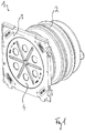
- Figure 1 shows an implementation 1 in an oblique view.
- the bushing 1 has a slip sleeve 2, which is discussed in detail below and is pushed onto a tubular element 20, also compare the section according to FIG Figure 2 .
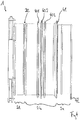
- the tubular element 20 extends away from a flange plate 3, with which the bushing 1 rests on a formwork when poured into a wall element, see also Figure 3 for illustration.
- the bushing 1 is closed at the end with the flange plate 3 with a cover 4, which can be removed after concreting and the actual line can then be laid.
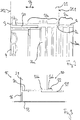
- FIG. 2 the concrete wall element 21 is indicated by dashed lines.
- a fitting section 2a is, in relation to a longitudinal direction 22 of the line, in the situation according to Figure 2 arranged outside the wall element 21.
- An assembly section 2b of the sleeve 2 lies within it.
- the everting section 2a is also arranged inside the wall element 21, namely it is turned inside.
- the slip section 2a and the mounting section 2b are connected to one another via a film hinge 2c.
- an inner wall surface 2aa of the everting section 2a bears against an inner wall surface 2ba of the mounting section 2b. Since the bushing 1 is cast in with the turned-in section 2a, a flat formwork element can be placed on both side surfaces 21.1, 21.2 of the wall element, which simplifies the formwork. Small wall thicknesses are also possible.
- a closure (not shown here) can additionally be inserted into the inlaid section 2a, which corresponds to the implementation 1 in the illustration Figure 2 closes on the right side. This is then removed after the pouring, and the everting section 2a is turned out.
- a protective tube 31 can then be inserted from the outside of a building 30, namely into the mounting section 2b and thus into the wall element 21.
- the protective tube 31 is thus kept stable against lateral forces.
- a clamping means 32 is arranged on an outer wall surface 2ab of the slip section 2a, which presses the slip section 2a onto the protective tube 31.
- the concrete borders on the outer wall surface 2bb of the mounting section 2b, the inserted protective tube 31 also bringing about a pressure to the outside and thus a tightness of this interface.
- Figure 4 shows the bushing 1 again in a side view on the outer wall surface 2bb of the mounting section 2b, web seals 40.1-40.3 can be seen, which together form a multi-wall seal. This is also pressed against the outside by the inserted protective tube 31.
- a circumferential lip 41 can be seen which bears against a formwork when the bushing 1 is poured in.
- a tab 42 can be seen at the end of the everted section 2a, which makes it easier for a fitter to put it out.
- the slip sleeve is provided with a further slip section 2d which hangs on the mounting section 2b via a film hinge 2e.
- the further everting section 2d is turned over, for adaptation to a tubular element with a smaller diameter it can be turned over.
- a clamping means (not shown here) can be arranged on the outside on the further slip section 2a in order to fix the slip sleeve 2 relative to the tubular element.
- the cut oblique view according to Figure 5 also reveals features located on the inside.
- the slip sleeve forms a stop 50, up to which the protective tube 31 can be inserted.
- two circumferential elevations 51 are formed on the inner wall surface 2ba in the mounting section 2b, which can be of interest, for example, with regard to a sealing contact with the protective tube 31.
- Complementary depressions 52 are provided on the inner wall surface 2aa of the slip section 2a, in which the elevations 51 come to rest when the slip section 2a is pushed in.
- Figure 6 shows a section of a toothed ring 60, namely from one Figure 5 opposite viewing direction, ie from the direction from which the protective tube 31 is inserted.
- the toothed ring 60 is arranged in the mounting section 2b, namely on the inside and between the elevations 51.
- the toothed ring 60 is shaped as a stamped and bent sheet metal part. It has a multiplicity of teeth 61 all around, along which the protective tube 31 can slide when inserted, but which claw in the opposite direction in its outer wall surface during a movement.
- the toothed ring 60 holds the protective tube 31 in position after it has been inserted, even before the clamping means 32 presses the everting section 2ab onto the protective tube 31.
- the toothed ring 60 can, as mentioned, be arranged in the mounting section 2b between the elevations 51, the recesses 52 then also being able to be combined in the slip section 2a, that is to say the two elevations 51 together with the toothed ring 60 can be placed in a common depression 52.
Landscapes
- Engineering & Computer Science (AREA)
- Architecture (AREA)
- Civil Engineering (AREA)
- Structural Engineering (AREA)
- Forms Removed On Construction Sites Or Auxiliary Members Thereof (AREA)
Abstract
Die Erfindung betrifft eine Verwendung einer Durchführung (1) zum Eingießen in ein Wandelement und Hindurchführen einer Leitung (33), wobei die Durchführung (1) einen Stülpabschnitt (2a) aufweist, der während des Eingießens der Durchführung (1) eingestülpt ist und nach dem Eingießen der Durchführung (1) ausgestülpt wird, wobei anschließend in den ausgestülpten Stülpabschnitt (2a) ein Schutzrohr (31) eingeschoben wird, in welchem Schutzrohr (31) die Leitung (33) verlegt wird.

Description
Die vorliegende Erfindung betrifft eine Durchführung zum Eingießen in ein Wandelement und Hindurchführen einer Leitung.The present invention relates to a bushing for pouring into a wall element and passing a line through it.
Das Eingießen der Durchführung erfolgt in der Regel im Zuge der Herstellung des Wandelements, wenn dieses also bspw. aus Beton gegossen wird. Die Durchführung kann dabei an einer Schalung montiert werden, anschließend sitzt sie baulich integriert in der Betonwand. Sie hält eine Durchgangsöffnung zwischen den einander entgegengesetzten Seitenflächen der Wand frei, durch die dann ein Kabel oder eine anderweitige Leitung verlegt werden kann.The implementation is usually poured in during the manufacture of the wall element, for example when it is poured from concrete. The bushing can be mounted on a formwork, after which it sits integrated in the concrete wall. It keeps a through opening between the opposite side surfaces of the wall free, through which a cable or other line can then be laid.
Der vorliegenden Erfindung liegt das technische Problem zugrunde, eine besonders vorteilhafte Verwendung bzw. Durchführung als Gegenstand der Verwendung anzugeben.The present invention is based on the technical problem of specifying a particularly advantageous use or implementation as the object of use.
Dies wird erfindungsgemäß mit der Verwendung gemäß Anspruch 1 gelöst. Die Durchführung weist einen Stülpabschnitt auf, der während des Eingießens der Durchführung eingestülpt ist und nach dem Eingießen ausgestülpt wird, wobei anschließend in den ausgestülpten Stülpabschnitt ein Schutzrohr eingeschoben wird. In dem Schutzrohr wird die eigentliche Leitung verlegt, etwa das Kabel bei dem Beispiel eingangs.This is achieved according to the invention with the use according to claim 1. The bushing has an everted section which is turned over during the pouring in of the bushing and is turned out after the pouring in, a protective tube then being inserted into the everted out section. The actual line is laid in the protective tube, for example the cable in the example at the beginning.
Diese Durchführung bzw. das Vorgehen nach den Schritten i.) - iii.) gemäß Anspruch 1 kann bspw. insoweit von Vorteil sein, als die Durchführung im eingestülpten Zustand (Schritt i) kompakt ist, was bspw. das Einschalen vereinfachen kann. Zudem ist auch ein Einbau in Wandelemente mit vergleichsweise geringer Dicke möglich. Der ausgestülpte Stülpabschnitt kann dann hingegen gut zugänglich sein, was das Einschieben des Schutzrohres bzw. ein etwaiges Befestigen davon vereinfachen kann. Das Schutzrohr wird typischerweise in einem Graben bzw. unter anderweitig beengten Verhältnissen (z. B. mehrere Schutzrohre neben- bzw. übereinander, siehe unten) an das Wandelement geführt, weswegen eine gute und einfache Handhabbarkeit von Vorteil ist. Das Ausstülpen des Stülpabschnitts ist insoweit auch ein vergleichsweise einfacher Vorgang, es muss bspw. nicht erst aufwendig eine Anschlussmuffe oder dergleichen an der eingegossenen Durchführung montiert werden. Dies kann bspw. auch hinsichtlich einer Verringerung der Zahl an Verbindungsstellen von Vorteil sein; speziell bei Arbeiten am Erdreich erhöht jede Verbindungsstelle die Gefahr einer möglichen Verschmutzung bei der Montage und damit einer möglichen späteren Undichtigkeit.This implementation or the procedure according to steps i.) - iii.) According to claim 1 can be advantageous, for example, insofar as the implementation in the inserted state (step i) is compact, which, for example, can simplify the shuttering. Installation in wall elements with a comparatively small thickness is also possible. The everted section can then be easily accessible, which can simplify the insertion of the protective tube or any fastening thereof. The protective tube is typically in a trench or under otherwise confined conditions (e.g. several protective tubes side by side or one above the other, see below) to the wall element, which is why good and easy handling is advantageous. In this respect, the protrusion of the everting section is also a comparatively simple process; for example, a connecting sleeve or the like does not have to be laboriously installed on the cast-in bushing. This can also be advantageous, for example, in terms of reducing the number of connection points; especially when working on the ground, each connection point increases the risk of possible contamination during assembly and thus possible later leakage.
Dies kann speziell hinsichtlich des zweischrittigen Verlegens von zunächst dem Schutzrohr und dann später der Leitung von Vorteil sein, das Anschließen des Schutzrohres kann dann nämlich in einer frühen Bauphase auf relativ einfache Weise möglich sein. Die eigentliche Leitung wird typischerweise erst deutlich später durch das Schutzrohr hindurch verlegt (durchgeschoben), bevorzugt ist das Schutzrohr in diesem Zeitpunkt dann bereits mit Erdreich bedeckt. Es ist dann also auch die Anschlussstelle von Durchführung und Schutzrohr nicht mehr zugänglich, weswegen der Qualität der zuvor durchgeführten Montagearbeiten besondere Bedeutung zukommt. Das Anschließen des Schutzrohres in der frühen Bauphase verdient also besondere Beachtung, zumal diese Arbeiten im Kontext der Erdarbeiten oftmals unter hohem Zeitdruck erfolgen (Kosten der Maschinen etc.). Die später hindurchgeführte Leitung wird zwar bevorzugt auch gesondert zur Durchführung hin abgedichtet, im Falle eines mangelhaft angeschlossenen Schutzrohres könnte jedoch bspw. ein zwischenzeitlicher Verschmutzungseintrag auch diese Dichtstelle beeinträchtigen.This can be particularly advantageous with regard to the two-step installation of the protective tube and then later the line, since connecting the protective tube can then be possible in a relatively simple manner in an early construction phase. The actual line is typically not laid (pushed through) significantly later through the protective tube; the protective tube is then preferably already covered with soil at this point. The connection point between the bushing and the protective tube is then no longer accessible, which is why the quality of the previously carried out assembly work is of particular importance. The connection of the protective tube in the early construction phase therefore deserves special attention, especially since this work in the context of earthworks often takes place under great time pressure (costs of the machines, etc.). The line which is passed through later is preferably also sealed off separately for implementation, but in the case of a deficiently connected protective tube, however, an intermittent contamination input could also impair this sealing point.
Weitere bevorzugte Ausgestaltungen finden sich in den abhängigen Ansprüchen und der gesamten Offenbarung. Diese richtet sich sowohl auf die Verwendung als auch auf ein entsprechendes Montageverfahren bzw. Verfahren zum Herstellen eines Wandelements mit eingegossener Durchführung.Further preferred configurations can be found in the dependent claims and the entire disclosure. This is directed both to the use and to a corresponding assembly method or method for producing a wall element with a cast-in bushing.
Das Schutzrohr kann bspw. einen Außendurchmesser von mindestens 50 mm, 70 mm, 90 mm bzw. 100 mm haben, mit möglichen (davon unabhängigen) Obergrenzen bei z. B. höchstens 300 mm, 250 mm, 200 mm bzw. 180 mm (jeweils in Reihenfolge der Nennung zunehmend bevorzugt). Der ausgestülpte Stülpabschnitt hat einen passenden Innendurchmesser, er kann beim Einschieben des Schutzrohres auch etwas gedehnt werden. In dem genannten Durchmesserbereich kann einerseits das Ausstülpen gut möglich sein (wird bei kleineren Durchmessern zunehmend schwieriger), andererseits sind die durch das Eigengewicht des Schutzrohres bedingten Kräfte dann auch noch nicht zu groß.The protective tube can, for example, have an outer diameter of at least 50 mm, 70 mm, 90 mm or 100 mm, with possible (independent) upper limits at z. B. at most 300 mm, 250 mm, 200 mm or 180 mm (increasingly preferred in each case in the order of mention). The everted section has a suitable inner diameter, it can also be slightly stretched when the protective tube is inserted. In the diameter range mentioned, on the one hand, the protrusion may well be possible (becomes increasingly difficult with smaller diameters), on the other hand, the forces caused by the weight of the protective tube are not yet too great.
Wie bereits erwähnt, wird der ausgestülpte Stülpabschnitt bevorzugt an dem Schutzrohr befestigt, besonders bevorzugt wird auf einer Außenwandfläche des Stülpabschnitts ein Spannmittel angeordnet, mit dem der Stülpabschnitt auf das Schutzrohr angedrückt wird. Es liegt dann eine Innenwandfläche des Stülpabschnitts zuverlässig dichtend gegen eine Außenwandfläche des Schutzrohres an. Als Spannmittel kann bspw. ein Spannband oder eine Spannschelle (mit Schraubenantrieb) vorgesehen sein.As already mentioned, the everted section is preferably attached to the protective tube, particularly preferably a clamping means is arranged on an outer wall surface of the everting section, with which the everting section is pressed onto the protective tube. An inner wall surface of the everting section then lies in a sealing manner against an outer wall surface of the protective tube. A tensioning strap or a tensioning clamp (with screw drive) can be provided as tensioning means.
Ohne ausdrücklich gegenteilige Angabe beziehen sich im Rahmen dieser Offenbarung "innen" und "außen" auf zu einer Rohrachse des Schutzrohres senkrechte, davon weg weisende Richtungen (im Folgenden auch als "Radialrichtungen" bezeichnet). Die Rohrachse, die bspw. auch mit einer Längsachse der von der Durchführung freigehaltenen Durchgangsöffnung zusammenfällt, ergibt sich aus der Orientierung des Schutzrohres dort, wo es in den Stülpabschnitt eingeschoben ist (inwiefern sich das Schutzrohr dann zur Wand beabstandet z. B. gekrümmt, erstreckt ist insofern unerheblich). Eine nachstehend in Bezug genommene "Längsrichtung der Leitung" liegt bevorzugt parallel zur Rohrachse (in der Praxis kann es selbstverständlich im vorliegenden Zusammenhang nicht weiter relevante Abweichungen von einer exakten Parallelität geben). Im Falle des Stülpabschnitts wird hinsichtlich der Zuordnung "innen"/"außen" der ausgestülpte Zustand zugrunde gelegt (eingestülpt kann also die Innenwandfläche nach außen gewandt sein, siehe unten). Die Angabe "umlaufend" bezieht sich auf einen Umlauf um die Rohrachse.In the context of this disclosure, "inside" and "outside" refer to directions perpendicular to a tube axis of the protective tube and pointing away therefrom (hereinafter also referred to as "radial directions"), unless expressly stated otherwise. The tube axis, which for example also coincides with a longitudinal axis of the through opening that is kept free of the bushing, results from the orientation of the protective tube where it is inserted into the everting section (to what extent the protective tube then extends, for example curved, spaced from the wall) is insignificant in this respect). A "longitudinal direction of the line" referred to below is preferably parallel to the pipe axis (in practice, there may of course be no further relevant deviations from an exact parallelism in the present context). In the case of the everting section, the turned-out state is used as the basis for the assignment "inside" / "outside" (so the inside wall surface can be turned in, see below). The term "revolving" refers to a revolution around the pipe axis.
In einem Schnitt senkrecht zur Rohr- bzw. Durchgangsöffnungs-Längsachse sind Kreisgeometrien bevorzugt, jedenfalls bei Stülpabschnitt und Schutzrohr bzw. auch der Durchgangsöffnung (diese wird in der Regel von einem Rohrelement freigehalten, siehe unten). Wie nachstehend im Kontext unterschiedlicher Merkmale deutlich wird, ist der Stülpabschnitt bevorzugt ein Teil bzw. Abschnitt einer Stülphülse. Diese ist aus einem Elastomermaterial vorgesehen, bevorzugt hat sie eine im Wesentlichen hohlzylindrische Form (also im eben genannten Schnitt eine Kreisform). Zur Ausbildung eines Filmscharniers kann die Wandstärke der Stülphülse in einem Axialschnitt betrachtet lokal verringert sein, im Vergleich zum Stülpabschnitt und/oder einem Montageabschnitt (siehe unten). Wenngleich eine Stülphülse bevorzugt ist, also eine im Gesamten aus dem Elastomermaterial geformte Hülse, könnte der Stülpabschnitt im Allgemeinen auch als Elastomerteil direkt an ein Rohrelement aus Hartkunststoff angeformt sein. Es könnte also bspw. in einem 2K-Spritzgussverfahren ein Rohrelement aus Hartkunststoff und an dieses der Stülpabschnitt aus bspw. einem thermoplastischen Elastomer gespritzt sein. Ebenso könnte die Stülphülse (mit Montageabschnitt etc.) direkt an das Rohrelement angespritzt sein, bevorzugt handelt es sich jedoch um separat hergestellte, zusammengesetzte Teile.In a section perpendicular to the longitudinal axis of the pipe or through opening, circular geometries are preferred, at least in the case of the slip section and protective tube or also the through opening (this is usually kept free of a pipe element, see below). As is clear below in the context of different features, the everting section is preferably a part or section of an everting sleeve. This is made of an elastomer material, preferably it has an essentially hollow cylindrical shape (ie a circular shape in the section just mentioned). To form a film hinge, the wall thickness of the slip sleeve can be reduced locally when viewed in an axial section, in comparison to the slip section and / or an assembly section (see below). Although an everting sleeve is preferred, that is to say a sleeve which is formed entirely from the elastomer material, the everting section could generally also be molded directly as an elastomer part onto a tubular element made of hard plastic. For example, in a two-component injection molding process, a tubular element made of hard plastic and the slip section made of, for example, a thermoplastic elastomer could be injection molded onto it. Likewise, the slip sleeve (with mounting section etc.) could be molded directly onto the tubular element, but it is preferably a matter of separately manufactured, assembled parts.
Das "Elastomermaterial" ist ganz allgemein ein Kunststoff mit elastischem Verhalten. Dessen Shore-Härte (Shore A) kann bspw. bei höchstens 90 Shore, 80 Shore, 75 Shore bzw. 70 Shore und (davon unabhängig) bspw. bei mindestens 20 Shore, 25 Shore, 30 Shore, 35 Shore bzw. 40 Shore liegen. Es kann sich bspw. um ein Kautschukmaterial handeln, vorzugsweise um einen Synthesekautschuk, etwa EPDM (Ethylen-Propylen-Dien, M-Gruppe). Ebenso kann es sich aber bspw. auch um einen Thermoplastischen Elastomer (TPE) oder ein Silikonbasiertes Material handeln, etwa Silikonkautschuk bzw. Silikonelastomer. Das Rohrelement kann bspw. eine Shore-Härte (D) von mindestens 50 Shore, 60 Shore bzw. 70 Shore haben, mit möglichen Obergrenzen bei höchstens 85 Shore bzw. 80 Shore, jedenfalls im Falle von Kunststoff.The "elastomer material" is generally a plastic with elastic behavior. Its Shore hardness (Shore A) can be, for example, at most 90 Shore, 80 Shore, 75 Shore or 70 Shore and (regardless of this), for example, at least 20 Shore, 25 Shore, 30 Shore, 35 Shore or 40 Shore . For example, it can be a rubber material, preferably a synthetic rubber, such as EPDM (ethylene propylene diene, M group). However, it can also be a thermoplastic elastomer (TPE) or a silicone-based material, such as silicone rubber or silicone elastomer. The tubular element can have, for example, a Shore hardness (D) of at least 50 Shore, 60 Shore or 70 Shore have, with possible upper limits at a maximum of 85 Shore or 80 Shore, at least in the case of plastic.
In bevorzugter Ausgestaltung ist der Stülpabschnitt in dem Schritt gemäß Ziffer i.) innerhalb und dann in dem Schritt gemäß Ziffer ii.) außerhalb des Wandelements angeordnet. Dies bezieht sich auf die Längsrichtung der Leitung, der Stülpabschnitt ist also aus Sicht des Wandelements gesehen eingestülpt diesseits einer Seitenfläche der Wand und ausgestülpt jenseits davon angeordnet. Dies kann bspw. insoweit von Vorteil sein, als beim Eingießen bspw. auch ein flächiges Schalungselement anliegen kann, also keine Überstände zu berücksichtigen sind. Anschließend beim Einschieben des Schutzrohres steht der Stülpabschnitt nach außen hervor und ist er damit besonders gut zugänglich, insbesondere zum Platzieren bzw. Betätigen eines Spannmittels.In a preferred embodiment, the slip section is arranged inside the step in accordance with number i.) And then in the step in accordance with number ii.) Outside the wall element. This relates to the longitudinal direction of the line, so the everted section is seen from the view of the wall element turned in on one side of the wall and turned out beyond it. This can be advantageous, for example, insofar as, for example, a flat formwork element can also be in place during the pouring in, so that no protrusions need to be taken into account. Then when the protective tube is pushed in, the everting section protrudes outwards and is therefore particularly easily accessible, in particular for placing or actuating a clamping device.
Gemäß einer bevorzugten Ausführungsform ist der Stülpabschnitt Teil einer Stülphülse (siehe vorne), wobei diese Stülphülse eine monolithisch mit dem Stülpabschnitt geformte, umlaufende Lippe aufweist. Diese Lippe liegt beim Eingießen an der Schalung an. Dazu erstreckt sie sich im unbelasteten Zustand, wenn also kein Schalungselement dagegen drückt, zu ihrem freien Ende hin bevorzugt schräg nach außen, also in Richtung des ausgestülpten Stülpabschnitts und dabei von der Rohrachse weg. Die Lippe ist bevorzugt radial außerhalb des Filmscharniers der Stülphülse angeordnet, sodass dieses von dem Vergussmaterial freigehalten gut beweglich bleibt.According to a preferred embodiment, the everting section is part of an everting sleeve (see above), this everting sleeve having a circumferential lip which is formed monolithically with the everting section. This lip lies against the formwork when pouring. For this purpose, it extends in the unloaded state, that is to say if no formwork element presses against it, preferably towards its free end obliquely outwards, that is to say in the direction of the everted section and away from the tube axis. The lip is preferably arranged radially outside the film hinge of the slip sleeve, so that it remains well movable, kept free from the potting material.
"Monolithisch" meint im Rahmen dieser Offenbarung frei von Materialgrenzen im Inneren, also Materialgrenzen zwischen unterschiedlichen Materialien bzw. Materialien unterschiedlicher Herstellungsgeschichte, jedenfalls von statistisch verteilten Einschlüssen abgesehen (z. B. Farbstoffpartikeln). Die "monolithische" Stülphülse ist bevorzugt ein Formteil, das in einem Schritt durch Gießen bzw. Pressen in eine Form hergestellt ist.In the context of this disclosure, “monolithic” means free of material boundaries in the interior, that is to say material boundaries between different materials or materials of different manufacturing history, in any case apart from statistically distributed inclusions (for example dye particles). The "monolithic" sleeve is preferably a molded part that is produced in one step by casting or pressing into a mold.
Gemäß einer bevorzugten Ausführungsform weist die Durchführung einen Zahnring auf. In diesen wird das Schutzrohr in dem Schritt gemäß Ziffer iii.) eingeschoben, der Zahnring hält es dann gegen ein Herausrutschen gesichert. Die zum Herausziehen des Schutzrohres aus dem Zahnring notwendige Kraft ist größer als die zum Einschieben notwendige Kraft, sie kann bspw. mindestens das 2-, 4-, 6-, 8- bzw. 10-fache ausmachen (mit möglichen Obergrenzen bei z. B. höchstens dem 1000-, 500-, 100- bzw. 50-fachen). Der Zahnring weist umlaufend verteilt eine Vielzahl Zähne auf (mindestens 10, 20, 30, 40 bzw. 50, mit möglichen Obergrenzen bei z. B. höchstens 500 bzw. 100), die sich nach dem Einschieben des Schutzrohres an diesem verkrallen (sobald dieses auch nur geringfügig entgegengesetzt der Einschieberichtung bewegt wird bzw. würde). Der Zahnring kann das eingeschobene Schutzrohr zuverlässig halten, was bspw. auch bereits während der Montage von Vorteil sein kann. Bevorzugt sind das Andrücken des Stülpabschnitts auf das eingeschobene Schutzrohr (mithilfe eines Spannmittels, siehe vorne) und die Fixierung mittels Zahnring kombinierte Maßnahmen, wobei der Zahnring auch das anschließende Andrücken des Stülpabschnitts vereinfachen kann (er hält das Schutzrohr und beugt so Montagefehlern vor). Generell liegt ein Vorteil des Zahnrings in der selbsttätigen, allein durch das Einschieben des Schutzrohres erreichten Fixierung.According to a preferred embodiment, the bushing has a toothed ring. The protective tube is pushed into this in the step according to number iii.), The toothed ring then holds it secured against slipping out. The force required to pull the protective tube out of the toothed ring is greater than the force required to insert it, for example it can be at least 2, 4, 6, 8 or 10 times greater (with possible upper limits for e.g. maximum 1000, 500, 100 or 50 times). The toothed ring has a multiplicity of teeth all around (at least 10, 20, 30, 40 or 50, with possible upper limits at, for example, at most 500 or 100), which cling to the protective tube after it has been inserted (as soon as this is or would be moved only slightly opposite to the direction of insertion). The toothed ring can hold the inserted protective tube reliably, which can also be advantageous during assembly, for example. Preference is given to pressing the slip section onto the inserted protective tube (with the aid of a clamping device, see above) and fixing by means of a toothed ring combined measures, the toothed ring also being able to simplify the subsequent pressing of the slip section (it holds the protective tube and thus prevents assembly errors). In general, one advantage of the toothed ring is the automatic fixation that is achieved simply by inserting the protective tube.
Im Allgemeinen ist bspw. auch ein Zahnring aus einem Hartkunststoff denkbar, speziell im Falle eines als Wellrohr bzw. Spiralschlauch vorgesehenen Schutzrohres. In bevorzugter Ausgestaltung ist der Zahnring jedoch ein Metallteil. Prinzipiell ist auch ein Frästeil denkbar, bevorzugt ist der Zahnring jedoch aus einem Blech herausgearbeitet, etwa durch Laserschneiden oder bevorzugt Stanzen (der Zahnring ist dann also ein Stanzteil). Der Zahnring kann bevorzugt umlaufend in sich geschlossen, im Allgemeinem aber bspw. auch mit einer Trennfuge vorgesehen sein (oder sogar auch mehrteilig). Prinzipiell ist denkbar, dass die Zähne des Zahnrings vor dem Einschieben des Schutzrohres noch eine dem Flächenmaterial bzw. Blech entsprechende Ausrichtung haben, also nicht bzw. allenfalls geringfügig aus der Ebene herausgebogen sind. Sie können sich bspw. gewinkelt, insbesondere senkrecht zur Rohrachse nach innen erstrecken und dann beim Einschieben des Schutzrohres von diesem in Einschieberichtung gebogen werden (und entgegen gesetzt eine Verkrallung schaffen). Bevorzugt sind die Zähne des als Laser- bzw. Stanzteil vorgesehenen Zahnrings jedoch bereits zuvor gebogen, haben Sie also bspw. in einem Axialschnitt betrachtet eine liegende U-bzw. V-Form. Diese Form ist entgegen der Einschieberichtung geschlossen, also in Einschieberichtung offen. Das Schutzrohr gleitet entsprechend beim Einschieben entlang der Zähne, in entgegengesetzter Richtung verkrallen sich diese.In general, for example, a toothed ring made of a hard plastic is also conceivable, especially in the case of a protective tube provided as a corrugated tube or spiral tube. In a preferred embodiment, however, the toothed ring is a metal part. In principle, a milled part is also conceivable, but the toothed ring is preferably machined out of a sheet metal, for example by laser cutting or preferably stamping (the toothed ring is then a stamped part). The toothed ring can preferably be self-contained all round, but in general it can also be provided, for example, with a parting line (or even in several parts). In principle, it is conceivable that the teeth of the toothed ring still have an orientation corresponding to the surface material or sheet metal before the protective tube is pushed in, that is to say that they are not, or at most only slightly, bent out of the plane. They can, for example, be angled, in particular extend inwards perpendicular to the pipe axis and then when they are inserted of the protective tube are bent in the direction of insertion (and create a claw in the opposite direction). However, the teeth of the toothed ring provided as a laser or stamped part are preferably already bent beforehand, so you have, for example, viewed in an axial section, a lying U or. V shape. This shape is closed against the direction of insertion, so open in the direction of insertion. The protective tube slides accordingly when inserted along the teeth, they claw in the opposite direction.
Gemäß einer bevorzugten Ausführungsform deckt der eingestülpte Stülpabschnitt den Zahnring nach innen ab, dieser ist während des Eingießens bzw. auch bereits zuvor (Lagerhaltung und Transport) geschützt. Prinzipiell könnte der Zahnring bspw. auch in die Dichthülse bzw. in ein Rohrelement der Durchführung eingeformt sein, also bspw. als Einlegeteil umspritzt. Bevorzugt handelt es sich um ein separates, eingesetztes Teil (auch unabhängig von der Abdeckung nach innen). Die bevorzugte Abdeckung nach innen kann in diesem Zusammenhang auch sicherstellen helfen, dass der Zahnring nicht verrutscht bzw. herausfällt, also dann beim Einschieben des Schutzrohres an der gewünschten Position sitzt.According to a preferred embodiment, the turned-in section covers the toothed ring on the inside, which is protected during the pouring or even beforehand (storage and transport). In principle, the toothed ring could, for example, also be molded into the sealing sleeve or into a pipe element of the bushing, that is, for example, overmoulded as an insert. It is preferably a separate, inserted part (also independent of the cover on the inside). In this context, the preferred cover on the inside can also help to ensure that the toothed ring does not slip or fall out, that is to say then sits at the desired position when the protective tube is inserted.
In bevorzugter Ausgestaltung ist während des Eingießen der Durchführung gemäß Ziffer i.) in den eingestülpten Stülpabschnitt ein Verschluss eingesetzt, der die Durchführung zu dieser Seite des Wandelements hin verschließt (zu der Seite, von welcher aus das Schutzrohr eingeschoben wird). Hierbei kann es sich bspw. um einen Rohrverschlussdeckel, einen Lamellenstopfen oder auch einen Schaumstoffkörper handeln, etwa eine Ronde aus expandiertem Polypropylen. Ist ein Zahnring vorgesehen, kann die eben diskutierte Abdeckung durch den eingestülpten Stülpabschnitt vorteilhafterweise auch einem Verkrallen des Verschlusses vorbeugen.In a preferred embodiment, during the pouring of the bushing according to item i.), A closure is inserted into the inlaid section, which closes the bushing to this side of the wall element (to the side from which the protective tube is inserted). This can be, for example, a pipe closure cover, a lamella plug or a foam body, for example a round blank made of expanded polypropylene. If a toothed ring is provided, the cover just discussed can advantageously also prevent the closure from clawing due to the inserted section.
Gemäß einer bevorzugten Ausführungsform ist der Stülpabschnitt Teil einer Dichthülse (siehe vorne) und ist der Zahnring in einem Montageabschnitt der Dichthülse angeordnet. Dieser Montageabschnitt sitzt sowohl bei dem Schritt gemäß Ziffer i.) als auch bei jenem gemäß iii.) innerhalb des Wandelements, ist dann also stabil eingebettet. Der dort angeordnete Zahnring kann das Schutzrohr entsprechend zuverlässig halten.According to a preferred embodiment, the slip section is part of a sealing sleeve (see above) and the toothed ring is arranged in an assembly section of the sealing sleeve. This assembly section sits within the wall element both in the step in accordance with number i.) And in that in accordance with iii.), And is then stable embedded. The toothed ring arranged there can hold the protective tube accordingly reliably.
Ganz allgemein wird das Schutzrohr in bevorzugter Ausgestaltung soweit eingeschoben, dass das Ende des Schutzrohres dann innerhalb des Wandelements liegt. Es kommt also das durch den ausgestülpten Stülpabschnitt eingeschobene Ende des Schutzrohres innerhalb des Wandelements zu liegen, ist also bei fertig bzw. vollständig eingeschobenen Schutzrohr dort angeordnet (in dieser Position wird dann bspw. der Stülpabschnitt am Schutzrohr befestigt und/oder die Leitung durch das Schutzrohr verlegt und insbesondere gegen die Durchführung gedichtet). Das Schutzrohr wird also ein Stück in eine von der Durchführung in dem Vergussmaterial (in der Regel Beton) freigehaltene Durchgangsöffnung eingeschoben, sodass vorteilhafterweise das Wandelement selbst eine Stabilisierungs- bzw. Stützfunktion übernimmt. Letzteres kann speziell im Vergleich zu dem eingangs als Alternativlösung geschilderten Ansetzen einer gesonderten Rohrmuffe von Vorteil sein. Die Abstützfunktion kann bspw. während der Bauphase vorteilhaft sein, wenn es bspw. durch unsachgemäße Handhabung (Betreten des Schutzrohres) oder auch anschließend zu einer Querbelastung kommt, bspw. durch ein Absacken des Erdreichs bei nicht hinreichender Verdichtung.In a preferred embodiment, the protective tube is very generally inserted so far that the end of the protective tube then lies within the wall element. So the end of the protective tube inserted through the everted section comes to lie within the wall element, so it is arranged there when the protective tube is completely or completely inserted (in this position, for example, the everting section is then attached to the protective tube and / or the line through the protective tube misplaced and especially sealed against the implementation). The protective tube is thus pushed a bit into a through-opening which is kept free of the passage in the potting material (usually concrete), so that the wall element itself advantageously takes on a stabilizing or supporting function. The latter can be particularly advantageous in comparison to the attachment of a separate pipe socket described at the beginning as an alternative solution. The support function can be advantageous, for example, during the construction phase, if, for example, improper handling (entering the protective tube) or a subsequent transverse load occurs, for example, if the soil sinks with insufficient compaction.
Wie bereits erwähnt, ist der Stülpabschnitt in bevorzugter Ausgestaltung Teil einer Stülphülse mit einem Montageabschnitt. Bevorzugt wird das Schutzrohr in dem Schritt gemäß Ziffer iii.) bis in den Montageabschnitt hinein eingeschoben (egal ob ohne oder bevorzugt mit einem Zahnring dort). Bevorzugt bildet die Stülphülse bzw. der Montageabschnitt einen Anschlag, bis zu welchem das Schutzrohr eingeschoben wird.As already mentioned, in a preferred embodiment, the slip section is part of a slip sleeve with a mounting section. The protective tube is preferably pushed into the assembly section in the step according to number iii. (Regardless of whether without or preferably with a toothed ring there). The sleeve or the mounting section preferably forms a stop, up to which the protective tube is inserted.
Gemäß einer bevorzugten Ausführungsform ist an einer Innenwandfläche des Montageabschnitts eine nach innen hervortretende, sich umlaufend (bevorzugt vollständig umlaufend) erstreckende Erhebung vorgesehen. Diese kann zum einen eine Anlage an dem dann eingeschobenen Schutzrohr sicherstellen, bspw. auch hinsichtlich der Dichtigkeit Relevanz haben. Zum anderen kann sie in Kombination mit dem Zahnring diesem eine definierte Axialposition vorgeben, ihn also gegen ein Verrutschen sichern. Bevorzugt sind mehrere Erhebungen vorgesehen, besonders bevorzugt genau zwei, dazwischen ist dann der Zahnring axial gesichert.According to a preferred embodiment, an inwardly protruding, circumferential (preferably completely circumferential) elevation is provided on an inner wall surface of the assembly section. On the one hand, this can ensure a system on the then inserted protective tube, for example also have relevance with regard to the tightness. On the other hand, it can be combined specify a defined axial position with the toothed ring, so secure it against slipping. A plurality of elevations are preferably provided, particularly preferably exactly two, in between the toothed ring is then axially secured.
In bevorzugter Ausgestaltung ist an einer Innenwandfläche des Stülpabschnitts eine Vertiefung vorgesehen, in welcher die Erhebung an der Innenwandfläche des Montageabschnitts angeordnet ist, wenn der Stülpabschnitt eingestülpt ist, also seine Innenwandfläche nach außen gewandt ist (vergleiche auch die vorstehenden Anmerkungen). Ist der Stülpabschnitt ausgestülpt, so stellt die Vertiefung eine nach innen offene Nut dar, im eingestülpten Zustand ist sie nach außen offen (und nimmt sie die Erhebung auf). Sind in dem Montageabschnitt mehrere Erhebungen vorgesehen, kann diesen jeweils eine eigene Vertiefung zugeordnet oder können sie auch in einer gemeinsamen Vertiefung angeordnet sein. Ist ein Zahnring vorgesehen, ist auch dieser bevorzugt in einer Vertiefung an der Innenwandfläche des eingestülpten Stülpabschnitts angeordnet, besonders bevorzugt gemeinsam mit dem bzw. den ihn axial einfassenden Erhebungen.In a preferred embodiment, an indentation is provided on an inner wall surface of the slip section, in which the elevation is arranged on the inner wall surface of the mounting section when the slip section is turned in, that is to say its inner wall surface is facing outwards (see also the comments above). If the everting section is turned out, the depression represents an inwardly open groove, in the inturned state it is open to the outside (and receives the elevation). If several elevations are provided in the assembly section, these can each be assigned a separate depression or they can also be arranged in a common depression. If a toothed ring is provided, this too is preferably arranged in a recess on the inner wall surface of the turned-in section, particularly preferably together with the elevation (s) that surround it axially.
In bevorzugter Ausgestaltung ist an dem Stülpabschnitt eine Lasche angeordnet, an welcher der eingestülpte Stülpabschnitt zum Ausstülpen gegriffen werden kann, vorzugsweise mit der Hand (oder auch mit einer Zange). Beim ausgestülpten Stülpabschnitt ist die Lasche bevorzugt an dessen axialem Ende angeordnet und erstreckt sie sich nach radial außen.In a preferred embodiment, a tab is arranged on the everting section, on which the everting can be gripped, preferably by hand (or with pliers). When the everted section, the tab is preferably arranged at its axial end and extends radially outward.
Ganz allgemein weist die Durchführung bevorzugt ein Rohrelement auf, das nach dem Eingießen in das Wandelement in diesem verbleibt, also nicht herausgenommen wird. Die Stülphülse und das Rohrelement haben axial einen Überlapp, jedenfalls der ausgestülpte Stülpabschnitt steht dann gegenüber dem Rohrelement axial hervor. Das Rohrelement ist bevorzugt aus einem Hartkunststoffmaterial vorgesehen, z. B. ABS oder PVC. Im Allgemeinen kann ein solches Rohrelement der Durchführung auch für sich die gesamte Durchgangsöffnung freihalten und kann die Stülphülse bzw. der eingestülpte Stülpabschnitt radial innerhalb davon angeordnet sein.In very general terms, the bushing preferably has a tubular element that remains in the wall element after it is poured into it, that is to say it is not removed. The sleeve and the tubular element have an axial overlap; in any case, the turned-over section protrudes axially from the tubular element. The tubular element is preferably provided from a hard plastic material, e.g. B. ABS or PVC. In general, such a pipe element of the bushing can also keep the entire passage opening free and the everting sleeve or the everting everting section can be arranged radially within it.
Gemäß einer bevorzugten Ausführungsform begrenzt jedoch ein Montageabschnitt der Stülphülse zumindest einen Abschnitt der Durchgangsöffnung in dem Wandelement. Es legt sich also das Vergussmaterial beim Eingießen an eine Außenwandfläche des Montageabschnitts an. Dies kann bspw. insoweit von Vorteil sein, als dann die Stülphülse, die hinsichtlich der Stülpbarkeit aus einem weichen Material vorgesehen ist, eine Grenzfläche zu dem Vergussmaterial bildet. Dieses härtet nach dem Gießen aus, wobei es zu einem Schrumpfen kommen kann. Das weiche Material der Stülphülse kann dann mit einer gewissen Elastizität noch in Kontakt mit dem gehärteten Vergussmaterial bleiben, also einer Spaltbildung und damit möglichen Kriechpfaden für Feuchtigkeit vorbeugen helfen. Besonders vorteilhaft kann insofern eine Kombination mit dem Einschieben des Schutzrohres in den Montageabschnitt und damit in das Wandelement hinein sein, weil dann zusätzlich das eingeschobene Schutzrohr den Montageabschnitt nach außen und damit in die Anlage an dem gehärteten Vergussmaterial drückt.According to a preferred embodiment, however, a mounting section of the slip sleeve delimits at least a section of the through opening in the wall element. The potting material therefore lies against an outer wall surface of the assembly section when it is poured in. This can be advantageous, for example, insofar as the slip sleeve, which is made of a soft material with regard to the slip ability, then forms an interface with the potting material. This hardens after casting, which can lead to shrinkage. The soft material of the everting sleeve can then still remain in contact with the hardened potting material with a certain elasticity, thus helping to prevent gaps and possible creeping paths for moisture. In this respect, a combination with the insertion of the protective tube into the mounting section and thus into the wall element can be particularly advantageous because the inserted protective tube then pushes the mounting section outwards and thus into the system on the hardened potting material.
In bevorzugter Ausgestaltung ist an der Außenwandfläche des Montageabschnitts, an welche sich das Vergussmaterial angelegt, eine sich nach außen erhebende, bevorzugt vollständig in sich geschlossen umlaufende Stegdichtung vorgesehen. Die Stegdichtung wird axial und nach außen hin von dem Vergussmaterial umschlossen. Bevorzugt können mehrere Stegdichtungen vorgesehen sein, also mindestens zwei und bspw. nicht mehr als fünf bzw. vier, besonders bevorzugt sind drei. Wie eben geschildert, kann das eingeschobene Schutzrohr dann auch die Stegdichtungen etwas nach außen und damit in eine dichtende Anlage drücken. Hinsichtlich einer Verkrallungsfunktion in dem Vergussmaterial kann sich eine jeweilige Stegdichtung zu ihrem freien Ende hin weiten, dann also mit einem Hinterschnitt in dem gehärteten Vergussmaterial sitzen. Bevorzugt erhebt sich eine jeweilige Stegdichtung jedoch hinterschnittfrei, weil dies die Herstellbarkeit der Durchführung bzw. Stülphülse in einem formenden Verfahren deutlich vereinfacht, speziell in Zusammenhang mit dem Andrücken nach außen durch das eingeschobene Schutzrohr jedoch keine Dichteinbußen ergibt.In a preferred embodiment, on the outer wall surface of the assembly section, to which the potting material is applied, a web seal that rises outwards, preferably completely self-contained, is provided. The web seal is axially and externally enclosed by the potting material. A plurality of web seals can preferably be provided, that is to say at least two and, for example, not more than five or four, and three are particularly preferred. As just described, the inserted protective tube can then push the web seals slightly outwards and thus into a sealing system. With regard to a claw function in the potting material, a respective web seal can widen towards its free end, that is to say then sit with an undercut in the hardened potting material. However, a respective web seal preferably rises without an undercut, because this significantly simplifies the manufacture of the bushing or slip sleeve in a molding process, especially in connection with the pressing outwards through the inserted protective tube, however, there is no loss of density.
Gemäß einer bevorzugten Ausführungsform ist der Montageabschnitt der Stülphülse auf ein Rohrelement der Durchführung aufgezogen, stützt also das Rohrelement den Montageabschnitt beim Eingießen nach radial innen ab. Bevorzugt ist das Rohrelement nur in einem Abschnitt des Montageabschnitts angeordnet (nicht im gesamten Montageabschnitt) und wird in einen anderen Abschnitt das Schutzrohr eingeschoben, siehe vorne. Das Rohrelement stützt die Stülphülse während des Eingießens ab, verbleibt dann jedoch auch darüber hinaus gemeinsam mit der Stülphülse in dem Wandelement; die beiden sind also dauerhaft baulich integriert, bspw. von Beton umschlossen. Das dauerhaft eingebaute Rohrelement kann bspw. auch mit Blick auf das spätere Hindurchführen bzw. -fädeln der Leitung vorteilhaft sein, hierbei nämlich einem Verrutschen der einzelnen Bestandteile der Durchführung innerhalb des Wandelements vorbeugen (das Leitungsende könnte sich verfangen und einzelne Teile verschieben, das Rohrelement schafft hierbei zusätzliche Stabilität).According to a preferred embodiment, the assembly section of the slip sleeve is drawn onto a tubular element of the bushing, that is to say the tubular element supports the assembly section radially inward during casting. The tubular element is preferably arranged only in one section of the assembly section (not in the entire assembly section) and the protective tube is inserted into another section, see above. The tubular element supports the sleeve during the pouring, but then also remains in the wall element together with the sleeve; the two are therefore permanently integrated in the building, for example surrounded by concrete. The permanently installed pipe element can, for example, also be advantageous with a view to the later passing or threading of the line, namely preventing the individual components of the bushing from slipping within the wall element (the end of the line could get caught and individual parts could move, the pipe element creates additional stability).
Gemäß einer bevorzugten Ausführungsform wird beim Ausstülpen des Stülpabschnitts aus dem ein- in den ausgestülpten Zustand um genau ein Filmscharnier gestülpt. Dies kann bspw. im Vergleich zu einem Ausstülpen um zwei Filmscharniere (zweifaches Ausstülpen) einen gewissen Nachteil dahingehend darstellen, dass die Außenwandfläche (ausgestülpter Zustand) im eingestülpten Zustand nach innen gewandt ist. Es kann dann bspw. keine Spannschelle als integrales Teil bereits im eingestülpten Zustand platziert sein, die entsprechend nach dem Ausstülpen automatisch an der richtigen Stelle sitzt. Bei dem zweifachen Ausstülpen ist dies hingegen möglich. Das einfache Ausstülpen ist dennoch hinsichtlich der Stabilität bevorzugt. Da der ausgestülpte Stülpabschnitt und der Montageabschnitt dann axial im Wesentlichen miteinander fluchten, kann das bis in den Montageabschnitt eingeschobene Schutzrohr dann in diesem und damit in dem Wandelement radial ohne maßgebliches Spiel abgestützt sein.According to a preferred embodiment, when the everting section is turned out, exactly one film hinge is turned over from the inturned state. For example, this can be a certain disadvantage compared to protruding around two film hinges (double protrusion) in that the outer wall surface (protruding state) faces inwards when the protruding state. In this case, for example, no clamping clamp can already be placed as an integral part in the inserted state, which automatically sits in the correct place after being inserted. However, this is possible with the double protrusion. The simple protrusion is preferred in terms of stability. Since the everted fitting section and the mounting section are then essentially axially aligned with one another, the protective tube inserted into the mounting section can then be supported radially in this and thus in the wall element without significant play.
Bei einer bevorzugten Ausführungsform ist die Stülphülse an ihren dem Stülpabschnitt entgegengesetzten Ende mit einem weiteren Stülpabschnitt ausgestattet. Dieser dient im Unterschied zu dem Stülpabschnitt für das Schutzrohr einer Anpassung an das Rohrelement der Durchführung. Hat das Rohrelement der Durchführung einen kleineren Außendurchmesser, kann der weitere Stülpabschnitt eingestülpt und kann so eine Anlage der Stülphülse an dem Rohrelement sichergestellt werden. Dies kann insbesondere bei dickeren Wänden der Fall sein, wenn nicht ein an einer Flanschplatte angeordneter Rohrstutzen selbst bzw. allein das Rohrelement bildet, sondern zusätzlich ein Verlängerungsrohr eingeschoben ist, vergleiche auch das Ausführungsbeispiel zur Illustration. Die Flanschplatte mit Rohrstutzen ist jenem Ende, in das das Schutzrohr eingeschoben wird, entgegengesetzt.In a preferred embodiment, the slip sleeve is equipped with a further slip section at its end opposite the slip section. In contrast to the everting section for the protective tube, this serves to adapt the tube element to the bushing. If the pipe element of the feedthrough has a smaller outside diameter, the further everting section can be turned in, and thus the fitting sleeve can be secured to the tubular element. This can be the case, in particular, in the case of thicker walls, if a pipe socket arranged on a flange plate does not itself or solely form the pipe element, but an extension pipe is additionally inserted, see also the exemplary embodiment for illustration. The flange plate with pipe socket is opposite to the end into which the protective tube is inserted.
Eine solche Flanschplatte, die als Teil der Durchführung nach dem Eingießen an der entgegengesetzten Seitenfläche des Wandelements liegt, kann generell bevorzugt sein. Die Flanschplatte kann einerseits der Montage an einem Schalungselement dienen, andererseits kann die Durchführung über die Flanschplatte auch mit weiteren Durchführungen modulartig zusammengebaut werden. Dazu können an den Außenkanten der Flanschplatte Formschlusselemente vorgesehen sein, bevorzugt sind sämtliche Durchführungen bzw. Flanschplatten eines Moduls baugleich, weist also jedes Formschlusselement zueinander komplementäre Formschlusselementteile auf (männlich/weiblich). Das vorstehend diskutierte Rohrelement der Durchführung bzw. zumindest ein Abschnitt (Rohrstutzen) davon ist bevorzugt einstückig bzw. monolithisch mit der Flanschplatte vorgesehen, auch unabhängig von deren Ausstattung mit Formschlusselementen etc. Je nach Dicke des Wandelements kann mit dem Rohrstutzen der Flanschplatte dann ein weiteres Rohrstück zusammengesetzt sein, um bei dickeren Wänden ein längeres Rohrelement zur Verfügung zu stellen. Die Stülphülse kann einerseits auf dem Rohrstutzen der Flanschplatte selbst sitzen (dünne Wände) oder auf einem damit zusammengesetzten Rohrstück (dicke Wände).Such a flange plate, which is part of the bushing after casting on the opposite side surface of the wall element, can generally be preferred. The flange plate can be used on the one hand for assembly on a formwork element, and on the other hand the bushing can also be assembled in a modular manner with other bushings. For this purpose, form-fit elements can be provided on the outer edges of the flange plate, preferably all feedthroughs or flange plates of a module are of identical construction, that is to say each form-fit element has mutually complementary form-fit element parts (male / female). The pipe element of the bushing discussed above or at least a section (pipe socket) thereof is preferably provided in one piece or monolithically with the flange plate, also regardless of its configuration with form-fitting elements etc. Depending on the thickness of the wall element, a further piece of pipe can then be used with the pipe socket of the flange plate be assembled to provide a longer pipe element for thicker walls. The sleeve can sit on the pipe socket of the flange plate itself (thin walls) or on a piece of pipe assembled with it (thick walls).
In bevorzugter Ausgestaltung ist das Wandelement eine Außenwand eines Gebäudes, also eines zu mehreren Seiten, bevorzugt insgesamt umbauten Raumes. Prinzipiell ist auch ein Wohngebäude denkbar, bevorzugt handelt es sich um ein Technikgebäude, bspw. eine Transformatorenstation (Umspannwerk). Das Schutzrohr erstreckt sich gebäudeaußenseitig, entsprechend wird auch der Stülpabschnitt zur Gebäudeaußenseite hin ausgestülpt. Von der Gebäudeinnenseite her wird bevorzugt eine Dichtung an die Durchführung gesetzt, welche dann die Leitung gegen die Durchführung dichtet. Dies kann bspw. mit einer Pressdichtung erfolgen (Elastomerkörper, der mit Spannbolzen axial komprimiert wird und sich radial dichtend anlegt), oder es kann bspw. auch ein Schrumpfschlauch-Einsatz Anwendung finden.In a preferred embodiment, the wall element is an outer wall of a building, that is to say a space which is enclosed on several sides, preferably in total. In principle, a residential building is also conceivable, preferably it is a technical building, for example a transformer station (substation). The protective tube extends on the outside of the building, and accordingly the everting section is also turned out to the outside of the building. From the inside of the building, a seal is preferably placed on the bushing, which then seals the line against the bushing. This can be done, for example, with a press seal (elastomer body, which is axially compressed with clamping bolts and is applied in a radially sealing manner), or, for example, a shrink tube insert can also be used.
Das Wandelement wird bevorzugt aus Beton gegossen, wobei die Durchführung vorzugsweise an einer Schalung befestigt wird, die nach dem Gießen des Wandelements entfernt wird.The wall element is preferably cast from concrete, the bushing preferably being fastened to a formwork which is removed after the wall element has been poured.
Offenbart sein soll auch eine Verwendung einer Durchführung zum Eingießen in ein Wandelement und Hindurchführen einer Leitung, wobei die Durchführung einen Stülpabschnitt aufweist, der
- i.) während des Eingießens der Durchführung eingestülpt ist und
- ii.) nach dem Eingießen der Durchführung ausgestülpt wird, wobei anschließend
- iii.) in den ausgestülpten Stülpabschnitt die Leitung eingeschoben wird, nämlich ein Kabel.
- i.) is turned in during the pouring of the bushing and
- ii.) is poured out after pouring the bushing, followed by
- iii.) the line, namely a cable, is inserted into the everted section.
In diesem Fall wird also nicht zuerst ein Schutzrohr eingeschoben und in diesem das Kabel (z. B. Elektro oder Daten) verlegt, sondern wird Letzteres direkt in den Stülpabschnitt eingeschoben (der Stülpabschnitt legt sich direkt an das Kabel an). Bei dieser Variante kann der Stülpabschnitt der Stülphülse (im ausgestülpten Zustand) auch einen deutlich geringeren Innendurchmesser als der Montageabschnitt der Stülphülse haben, bspw. von höchstens 1/2, 1/3 bzw. 1/4 (mit möglichen Untergrenzen bei z. B. mindestens 1/30 bzw. 1/20). Generell sitzt der Montageabschnitt auch bei dieser Variante bevorzugt auf einem Rohrelement der Durchführung, welches die Stülphülse beim Eingießen und auch darüber hinaus abstützt und stabilisiert. Generell wird bezüglich bevorzugter Möglichkeiten der Ausgestaltung ausdrücklich auf die vorstehende Offenbarung und auch die abhängigen Ansprüche verwiesen, die auch hinsichtlich eines direkt in die Stülphülse bzw. den Stülpabschnitt eingeschobenen Kabels bevorzugt sind (sofern sie nicht das Zusammenwirken von Schutzrohr und Durchführung betreffen).In this case, therefore, a protective tube is not first inserted and the cable (e.g. electrical or data) is laid in it, but the latter is inserted directly into the evert section (the everting section attaches itself directly to the cable). In this variant, the slip section of the slip sleeve (in the unfolded state) can also have a significantly smaller inside diameter than the mounting section of the slip sleeve, for example of at most 1/2, 1/3 or 1/4 (with possible lower limits for e.g. at least 1/30 or 1/20). In general, the mounting section also preferably sits on a tubular element in this variant Execution, which supports and stabilizes the slip sleeve during pouring and beyond. In general, with regard to preferred design options, reference is expressly made to the above disclosure and also to the dependent claims, which are also preferred with regard to a cable inserted directly into the sleeve or the sleeve section (provided they do not relate to the interaction of the protective tube and bushing).
Bei dieser Variante kann die Stülphülse insbesondere auch zum Hindurchführen mehrerer Kabel ausgelegt sein, also mehrere Stülpabschnitte aufweisen. Diese können an einer Stirnseite der Stülphülse im ausgestülpten Zustand jeweils axial hervortretenden, auf der axial entgegengesetzten Seite der Stirnseite erstreckt sich der Montageabschnitt. Unabhängig davon im Einzelnen kann der bzw. können die Stülpabschnitte auf das jeweilige Kabel dann bspw. jeweils mit einem Spannmittel (z. B. Spannband oder Spannschelle, siehe vorne) angedrückt werden. Der Montageabschnitt ist, wie ebenfalls vorstehend dargelegt, von dem Vergussmaterial, insbesondere Beton des Wandelements umschlossen.In this variant, the everting sleeve can in particular also be designed for the passage of a plurality of cables, that is to say can have a plurality of everting sections. These can protrude axially on one end face of the everting sleeve in the slipped-out state, and the assembly section extends on the axially opposite side of the end face. Irrespective of this in detail, the slip section or sections can then be pressed onto the respective cable, for example, in each case with a tensioning means (e.g. tensioning strap or tensioning clamp, see above). As also explained above, the assembly section is enclosed by the potting material, in particular concrete, of the wall element.
Im Folgenden wird die Erfindung anhand eines Ausführungsbeispiels näher erläutert, wobei die einzelnen Merkmale im Rahmen des Hauptanspruchs auch in anderer Kombination erfindungswesentlich sein können.The invention is explained in more detail below on the basis of an exemplary embodiment, the individual features within the scope of the main claim also being essential to the invention in a different combination.
Im Einzelnen zeigt
- Figur 1
- eine Durchführung mit einer Stülphülse in einer Schrägansicht;
Figur 2- eine geschnittene Seitenansicht zu der Durchführung gemäß
Figur 1 ; Figur 3- in schematischer Darstellung die Installation einer Durchführung gemäß den
Figuren 1 und2 ; - Figur 4
- zu der Durchführung gemäß den
Figuren 1 und2 eine Seitenansicht; - Figur 5
- die Stülphülse der Durchführung gemäß
den Figuren 1 ,2 und4 in einer geschnittenen Schrägansicht; - Figur 6
- einen Zahnring zum Anordnen in der Stülphülse.
- Figure 1
- an implementation with a sleeve in an oblique view;
- Figure 2
- a sectional side view of the implementation according to
Figure 1 ; - Figure 3
- the installation of a implementation according to the
Figures 1 and2nd ; - Figure 4
- for implementation in accordance with
Figures 1 and2nd a side view; - Figure 5
- the sleeve of the implementation according to the
Figures 1 ,2nd and4th in a sectional oblique view; - Figure 6
- a toothed ring to be placed in the sleeve.
In
Während des Einbetonierens kann in den eingestülpten Stülpabschnitt 2a zusätzlich ein hier nicht dargestellter Verschluss eingesetzt sein, der die Durchführung 1 in der Darstellung gemäß
Wie
Nach dem Anschließen des Schutzrohres 31 kann auf der Gebäudeaußenseite 30 bereits mit Erdreich aufgeschüttet werden und ist die Installation insoweit abgeschlossen. Zum Verlegen einer Leitung 33 wird später der Verschlussdeckel 4 aus dem Rohrelement 20 genommen, die Leitung 33 kann von der Gebäudeinnenseite 35 oder auch von einer gebäudeaußenseitigen Zugangsstelle durch das Schutzrohr 31 geschoben werden. Anschließend wird eine Dichtung 36 platziert, welche die Durchführung 1 gegen die Leitung 33 abdichtet.After connecting the
An dem dem Stülpabschnitt 2a entgegengesetzten Ende ist die Stülphülse mit einem weiteren Stülpabschnitt 2d versehen, der über ein Filmscharnier 2e an dem Montageabschnitt 2b hängt. In
Die geschnittene Schrägansicht gemäß
Bezogen auf die Darstellung gemäß
Claims (15)
wobei die Durchführung (1) einen Stülpabschnitt (2a) aufweist, der
wherein the bushing (1) has a slip section (2a) which
Priority Applications (2)
| Application Number | Priority Date | Filing Date | Title |
|---|---|---|---|
| EP18213036.9A EP3672003B1 (en) | 2018-12-17 | 2018-12-17 | Use of a feed through for casting into a wall element |
| PL18213036.9T PL3672003T3 (en) | 2018-12-17 | 2018-12-17 | Use of a feed through for casting into a wall element |
Applications Claiming Priority (1)
| Application Number | Priority Date | Filing Date | Title |
|---|---|---|---|
| EP18213036.9A EP3672003B1 (en) | 2018-12-17 | 2018-12-17 | Use of a feed through for casting into a wall element |
Publications (3)
| Publication Number | Publication Date |
|---|---|
| EP3672003A1 true EP3672003A1 (en) | 2020-06-24 |
| EP3672003B1 EP3672003B1 (en) | 2023-11-22 |
| EP3672003C0 EP3672003C0 (en) | 2023-11-22 |
Family
ID=64744425
Family Applications (1)
| Application Number | Title | Priority Date | Filing Date |
|---|---|---|---|
| EP18213036.9A Active EP3672003B1 (en) | 2018-12-17 | 2018-12-17 | Use of a feed through for casting into a wall element |
Country Status (2)
| Country | Link |
|---|---|
| EP (1) | EP3672003B1 (en) |
| PL (1) | PL3672003T3 (en) |
Citations (7)
| Publication number | Priority date | Publication date | Assignee | Title |
|---|---|---|---|---|
| DE2120070A1 (en) * | 1971-04-24 | 1972-11-16 | Beton-Bau Gmbh, 6833 Kirrlach | Waterproof wall duct for electrical cables |
| DE3005144A1 (en) * | 1980-02-12 | 1981-08-20 | Hans 8100 Garmisch-Partenkirchen Langmatz | Flush-fitting embedded cable seal - has cover incorporating sealing sleeves with locating flange fitting over open mouth of base |
| US5941535A (en) * | 1997-05-29 | 1999-08-24 | Richard; James G. | Cast-in-place pipe support having a reversible pipe seal and removable closure disk |
| EP2899332A1 (en) * | 2014-01-23 | 2015-07-29 | Hauff-Technik GmbH & Co. KG | Feed-through for installation in a wall or floor element |
| US20150263498A1 (en) * | 2014-03-13 | 2015-09-17 | Hubbell Incorporated | Push to connect weatherproof box |
| EP3061890A1 (en) * | 2015-02-26 | 2016-08-31 | Hauff-Technik GmbH & Co. KG | Feed-through for casting with concrete |
| EP3255330A1 (en) * | 2016-06-09 | 2017-12-13 | Hauff-Technik GmbH & Co. KG | Use of a sealing sleeve |
Family Cites Families (2)
| Publication number | Priority date | Publication date | Assignee | Title |
|---|---|---|---|---|
| FR2557388B1 (en) * | 1983-09-23 | 1986-12-26 | Lebrun Marie Therese | PREFABRICATED MASK AND ASSOCIATED GLAND FOR WATERPROOF PASSAGE THROUGH A WALL |
| DE10007527C2 (en) * | 2000-02-18 | 2003-05-22 | Hauff Technik Gmbh & Co Kg | Sealing packing for leading cables through a wall |
-
2018
- 2018-12-17 EP EP18213036.9A patent/EP3672003B1/en active Active
- 2018-12-17 PL PL18213036.9T patent/PL3672003T3/en unknown
Patent Citations (7)
| Publication number | Priority date | Publication date | Assignee | Title |
|---|---|---|---|---|
| DE2120070A1 (en) * | 1971-04-24 | 1972-11-16 | Beton-Bau Gmbh, 6833 Kirrlach | Waterproof wall duct for electrical cables |
| DE3005144A1 (en) * | 1980-02-12 | 1981-08-20 | Hans 8100 Garmisch-Partenkirchen Langmatz | Flush-fitting embedded cable seal - has cover incorporating sealing sleeves with locating flange fitting over open mouth of base |
| US5941535A (en) * | 1997-05-29 | 1999-08-24 | Richard; James G. | Cast-in-place pipe support having a reversible pipe seal and removable closure disk |
| EP2899332A1 (en) * | 2014-01-23 | 2015-07-29 | Hauff-Technik GmbH & Co. KG | Feed-through for installation in a wall or floor element |
| US20150263498A1 (en) * | 2014-03-13 | 2015-09-17 | Hubbell Incorporated | Push to connect weatherproof box |
| EP3061890A1 (en) * | 2015-02-26 | 2016-08-31 | Hauff-Technik GmbH & Co. KG | Feed-through for casting with concrete |
| EP3255330A1 (en) * | 2016-06-09 | 2017-12-13 | Hauff-Technik GmbH & Co. KG | Use of a sealing sleeve |
Also Published As
| Publication number | Publication date |
|---|---|
| EP3672003B1 (en) | 2023-11-22 |
| PL3672003T3 (en) | 2024-03-04 |
| EP3672003C0 (en) | 2023-11-22 |
Similar Documents
| Publication | Publication Date | Title |
|---|---|---|
| EP2899332B1 (en) | Use of a feed-through for installation in a wall or floor element | |
| DE29723989U1 (en) | Device for joining precast concrete parts | |
| DE60206930T2 (en) | DEVICE WITH A SEAL BETWEEN TWO HOUSING TABLES | |
| EP1288554A1 (en) | Connection means for a pipe | |
| EP3672003B1 (en) | Use of a feed through for casting into a wall element | |
| EP2338658A1 (en) | Method for manufacturing a seal | |
| DE69616381T2 (en) | LOCKING DEVICE | |
| EP3288130B1 (en) | Use of an inlet in a building for insertion into an outer wall of a building | |
| EP3327884B1 (en) | Pipe introduction | |
| DE2937605C2 (en) | Molding device for overmolding or casting around the edge of a flat component | |
| EP2028740A1 (en) | Mounting plate for electric installations | |
| EP1528011B1 (en) | Coaxial two component cartridge | |
| DE102018005720B4 (en) | Use of a grommet for pouring into a floor slab | |
| DE102022124664A1 (en) | Use of an insert for mounting in a wall or floor element | |
| EP3061890B1 (en) | Feed-through for casting with concrete | |
| EP2363552B1 (en) | Use of an attachment piece for attachment to a seal | |
| EP2937493B1 (en) | Feed-through for a floor or ceiling element | |
| EP2426280B1 (en) | Centring sealing ring for a sanitary fitting, in particular a sink fitting | |
| EP2385286B1 (en) | Circuit lead through with a sequence of layers | |
| DE102023127011A1 (en) | Press seal for sealing a pipe against a side surface of a wall or floor element | |
| DE69001441T2 (en) | CAN WITH BREAKOUT OPENINGS FOR BUILT-IN DEVICES, ESPECIALLY FOR ELECTRICAL DEVICES. | |
| DE3318754A1 (en) | Diaphragm and method for its manufacture | |
| EP4594663A1 (en) | Use of an elastomer sleeve for assembly on a line | |
| DE102022124662A1 (en) | Use of an insert for mounting in a wall or floor element | |
| DE202015001458U1 (en) | Pouring with concrete |
Legal Events
| Date | Code | Title | Description |
|---|---|---|---|
| PUAI | Public reference made under article 153(3) epc to a published international application that has entered the european phase |
Free format text: ORIGINAL CODE: 0009012 |
|
| STAA | Information on the status of an ep patent application or granted ep patent |
Free format text: STATUS: THE APPLICATION HAS BEEN PUBLISHED |
|
| AK | Designated contracting states |
Kind code of ref document: A1 Designated state(s): AL AT BE BG CH CY CZ DE DK EE ES FI FR GB GR HR HU IE IS IT LI LT LU LV MC MK MT NL NO PL PT RO RS SE SI SK SM TR |
|
| AX | Request for extension of the european patent |
Extension state: BA ME |
|
| STAA | Information on the status of an ep patent application or granted ep patent |
Free format text: STATUS: REQUEST FOR EXAMINATION WAS MADE |
|
| 17P | Request for examination filed |
Effective date: 20201222 |
|
| RBV | Designated contracting states (corrected) |
Designated state(s): AL AT BE BG CH CY CZ DE DK EE ES FI FR GB GR HR HU IE IS IT LI LT LU LV MC MK MT NL NO PL PT RO RS SE SI SK SM TR |
|
| STAA | Information on the status of an ep patent application or granted ep patent |
Free format text: STATUS: EXAMINATION IS IN PROGRESS |
|
| 17Q | First examination report despatched |
Effective date: 20211222 |
|
| 17Q | First examination report despatched |
Effective date: 20220217 |
|
| GRAP | Despatch of communication of intention to grant a patent |
Free format text: ORIGINAL CODE: EPIDOSNIGR1 |
|
| STAA | Information on the status of an ep patent application or granted ep patent |
Free format text: STATUS: GRANT OF PATENT IS INTENDED |
|
| RIC1 | Information provided on ipc code assigned before grant |
Ipc: F16L 5/02 20060101ALN20230624BHEP Ipc: F16L 5/00 20060101ALI20230624BHEP Ipc: H02G 3/22 20060101AFI20230624BHEP |
|
| INTG | Intention to grant announced |
Effective date: 20230707 |
|
| GRAS | Grant fee paid |
Free format text: ORIGINAL CODE: EPIDOSNIGR3 |
|
| GRAA | (expected) grant |
Free format text: ORIGINAL CODE: 0009210 |
|
| STAA | Information on the status of an ep patent application or granted ep patent |
Free format text: STATUS: THE PATENT HAS BEEN GRANTED |
|
| AK | Designated contracting states |
Kind code of ref document: B1 Designated state(s): AL AT BE BG CH CY CZ DE DK EE ES FI FR GB GR HR HU IE IS IT LI LT LU LV MC MK MT NL NO PL PT RO RS SE SI SK SM TR |
|
| REG | Reference to a national code |
Ref country code: GB Ref legal event code: FG4D Free format text: NOT ENGLISH |
|
| REG | Reference to a national code |
Ref country code: CH Ref legal event code: EP Ref country code: DE Ref legal event code: R096 Ref document number: 502018013662 Country of ref document: DE |
|
| REG | Reference to a national code |
Ref country code: IE Ref legal event code: FG4D Free format text: LANGUAGE OF EP DOCUMENT: GERMAN |
|
| U01 | Request for unitary effect filed |
Effective date: 20231123 |
|
| U07 | Unitary effect registered |
Designated state(s): AT BE BG DE DK EE FI FR IT LT LU LV MT NL PT SE SI Effective date: 20231129 |
|
| U20 | Renewal fee for the european patent with unitary effect paid |
Year of fee payment: 6 Effective date: 20240215 |
|
| PG25 | Lapsed in a contracting state [announced via postgrant information from national office to epo] |
Ref country code: GR Free format text: LAPSE BECAUSE OF FAILURE TO SUBMIT A TRANSLATION OF THE DESCRIPTION OR TO PAY THE FEE WITHIN THE PRESCRIBED TIME-LIMIT Effective date: 20240223 |
|
| PG25 | Lapsed in a contracting state [announced via postgrant information from national office to epo] |
Ref country code: IS Free format text: LAPSE BECAUSE OF FAILURE TO SUBMIT A TRANSLATION OF THE DESCRIPTION OR TO PAY THE FEE WITHIN THE PRESCRIBED TIME-LIMIT Effective date: 20240322 |
|
| PG25 | Lapsed in a contracting state [announced via postgrant information from national office to epo] |
Ref country code: ES Free format text: LAPSE BECAUSE OF FAILURE TO SUBMIT A TRANSLATION OF THE DESCRIPTION OR TO PAY THE FEE WITHIN THE PRESCRIBED TIME-LIMIT Effective date: 20231122 |
|
| PG25 | Lapsed in a contracting state [announced via postgrant information from national office to epo] |
Ref country code: IS Free format text: LAPSE BECAUSE OF FAILURE TO SUBMIT A TRANSLATION OF THE DESCRIPTION OR TO PAY THE FEE WITHIN THE PRESCRIBED TIME-LIMIT Effective date: 20240322 Ref country code: GR Free format text: LAPSE BECAUSE OF FAILURE TO SUBMIT A TRANSLATION OF THE DESCRIPTION OR TO PAY THE FEE WITHIN THE PRESCRIBED TIME-LIMIT Effective date: 20240223 Ref country code: ES Free format text: LAPSE BECAUSE OF FAILURE TO SUBMIT A TRANSLATION OF THE DESCRIPTION OR TO PAY THE FEE WITHIN THE PRESCRIBED TIME-LIMIT Effective date: 20231122 |
|
| PG25 | Lapsed in a contracting state [announced via postgrant information from national office to epo] |
Ref country code: RS Free format text: LAPSE BECAUSE OF FAILURE TO SUBMIT A TRANSLATION OF THE DESCRIPTION OR TO PAY THE FEE WITHIN THE PRESCRIBED TIME-LIMIT Effective date: 20231122 Ref country code: NO Free format text: LAPSE BECAUSE OF FAILURE TO SUBMIT A TRANSLATION OF THE DESCRIPTION OR TO PAY THE FEE WITHIN THE PRESCRIBED TIME-LIMIT Effective date: 20240222 Ref country code: HR Free format text: LAPSE BECAUSE OF FAILURE TO SUBMIT A TRANSLATION OF THE DESCRIPTION OR TO PAY THE FEE WITHIN THE PRESCRIBED TIME-LIMIT Effective date: 20231122 |
|
| PG25 | Lapsed in a contracting state [announced via postgrant information from national office to epo] |
Ref country code: SK Free format text: LAPSE BECAUSE OF FAILURE TO SUBMIT A TRANSLATION OF THE DESCRIPTION OR TO PAY THE FEE WITHIN THE PRESCRIBED TIME-LIMIT Effective date: 20231122 |
|
| PG25 | Lapsed in a contracting state [announced via postgrant information from national office to epo] |
Ref country code: SM Free format text: LAPSE BECAUSE OF FAILURE TO SUBMIT A TRANSLATION OF THE DESCRIPTION OR TO PAY THE FEE WITHIN THE PRESCRIBED TIME-LIMIT Effective date: 20231122 Ref country code: SK Free format text: LAPSE BECAUSE OF FAILURE TO SUBMIT A TRANSLATION OF THE DESCRIPTION OR TO PAY THE FEE WITHIN THE PRESCRIBED TIME-LIMIT Effective date: 20231122 Ref country code: RO Free format text: LAPSE BECAUSE OF FAILURE TO SUBMIT A TRANSLATION OF THE DESCRIPTION OR TO PAY THE FEE WITHIN THE PRESCRIBED TIME-LIMIT Effective date: 20231122 |
|
| REG | Reference to a national code |
Ref country code: DE Ref legal event code: R097 Ref document number: 502018013662 Country of ref document: DE |
|
| PG25 | Lapsed in a contracting state [announced via postgrant information from national office to epo] |
Ref country code: MC Free format text: LAPSE BECAUSE OF FAILURE TO SUBMIT A TRANSLATION OF THE DESCRIPTION OR TO PAY THE FEE WITHIN THE PRESCRIBED TIME-LIMIT Effective date: 20231122 |
|
| PG25 | Lapsed in a contracting state [announced via postgrant information from national office to epo] |
Ref country code: MC Free format text: LAPSE BECAUSE OF FAILURE TO SUBMIT A TRANSLATION OF THE DESCRIPTION OR TO PAY THE FEE WITHIN THE PRESCRIBED TIME-LIMIT Effective date: 20231122 |
|
| PLBE | No opposition filed within time limit |
Free format text: ORIGINAL CODE: 0009261 |
|
| STAA | Information on the status of an ep patent application or granted ep patent |
Free format text: STATUS: NO OPPOSITION FILED WITHIN TIME LIMIT |
|
| REG | Reference to a national code |
Ref country code: IE Ref legal event code: MM4A |
|
| PG25 | Lapsed in a contracting state [announced via postgrant information from national office to epo] |
Ref country code: IE Free format text: LAPSE BECAUSE OF NON-PAYMENT OF DUE FEES Effective date: 20231217 |
|
| 26N | No opposition filed |
Effective date: 20240823 |
|
| PG25 | Lapsed in a contracting state [announced via postgrant information from national office to epo] |
Ref country code: IE Free format text: LAPSE BECAUSE OF NON-PAYMENT OF DUE FEES Effective date: 20231217 |
|
| U20 | Renewal fee for the european patent with unitary effect paid |
Year of fee payment: 7 Effective date: 20241219 |
|
| PG25 | Lapsed in a contracting state [announced via postgrant information from national office to epo] |
Ref country code: CY Free format text: LAPSE BECAUSE OF FAILURE TO SUBMIT A TRANSLATION OF THE DESCRIPTION OR TO PAY THE FEE WITHIN THE PRESCRIBED TIME-LIMIT; INVALID AB INITIO Effective date: 20181217 |
|
| PG25 | Lapsed in a contracting state [announced via postgrant information from national office to epo] |
Ref country code: HU Free format text: LAPSE BECAUSE OF FAILURE TO SUBMIT A TRANSLATION OF THE DESCRIPTION OR TO PAY THE FEE WITHIN THE PRESCRIBED TIME-LIMIT; INVALID AB INITIO Effective date: 20181217 |
|
| PG25 | Lapsed in a contracting state [announced via postgrant information from national office to epo] |
Ref country code: TR Free format text: LAPSE BECAUSE OF FAILURE TO SUBMIT A TRANSLATION OF THE DESCRIPTION OR TO PAY THE FEE WITHIN THE PRESCRIBED TIME-LIMIT Effective date: 20231122 |
|
| REG | Reference to a national code |
Ref country code: CH Ref legal event code: U11 Free format text: ST27 STATUS EVENT CODE: U-0-0-U10-U11 (AS PROVIDED BY THE NATIONAL OFFICE) Effective date: 20260101 |
|
| PGFP | Annual fee paid to national office [announced via postgrant information from national office to epo] |
Ref country code: GB Payment date: 20251216 Year of fee payment: 8 |
|
| PGFP | Annual fee paid to national office [announced via postgrant information from national office to epo] |
Ref country code: CZ Payment date: 20251204 Year of fee payment: 8 |
|
| U20 | Renewal fee for the european patent with unitary effect paid |
Year of fee payment: 8 Effective date: 20251216 |
|
| PGFP | Annual fee paid to national office [announced via postgrant information from national office to epo] |
Ref country code: PL Payment date: 20251209 Year of fee payment: 8 |
|
| PGFP | Annual fee paid to national office [announced via postgrant information from national office to epo] |
Ref country code: CH Payment date: 20260101 Year of fee payment: 8 |