EP3672039A1 - Stellantrieb für ein stellorgan zur steuerung eines fluides - Google Patents
Stellantrieb für ein stellorgan zur steuerung eines fluides Download PDFInfo
- Publication number
- EP3672039A1 EP3672039A1 EP19193362.1A EP19193362A EP3672039A1 EP 3672039 A1 EP3672039 A1 EP 3672039A1 EP 19193362 A EP19193362 A EP 19193362A EP 3672039 A1 EP3672039 A1 EP 3672039A1
- Authority
- EP
- European Patent Office
- Prior art keywords
- actuator
- drive
- motor
- coils
- unit
- Prior art date
- Legal status (The legal status is an assumption and is not a legal conclusion. Google has not performed a legal analysis and makes no representation as to the accuracy of the status listed.)
- Granted
Links
Images

Classifications
-
- H—ELECTRICITY
- H02—GENERATION; CONVERSION OR DISTRIBUTION OF ELECTRIC POWER
- H02K—DYNAMO-ELECTRIC MACHINES
- H02K16/00—Machines with more than one rotor or stator
- H02K16/02—Machines with one stator and two or more rotors
-
- F—MECHANICAL ENGINEERING; LIGHTING; HEATING; WEAPONS; BLASTING
- F01—MACHINES OR ENGINES IN GENERAL; ENGINE PLANTS IN GENERAL; STEAM ENGINES
- F01P—COOLING OF MACHINES OR ENGINES IN GENERAL; COOLING OF INTERNAL-COMBUSTION ENGINES
- F01P3/00—Liquid cooling
- F01P3/20—Cooling circuits not specific to a single part of engine or machine
-
- F—MECHANICAL ENGINEERING; LIGHTING; HEATING; WEAPONS; BLASTING
- F01—MACHINES OR ENGINES IN GENERAL; ENGINE PLANTS IN GENERAL; STEAM ENGINES
- F01P—COOLING OF MACHINES OR ENGINES IN GENERAL; COOLING OF INTERNAL-COMBUSTION ENGINES
- F01P7/00—Controlling of coolant flow
- F01P7/14—Controlling of coolant flow the coolant being liquid
- F01P7/16—Controlling of coolant flow the coolant being liquid by thermostatic control
- F01P7/165—Controlling of coolant flow the coolant being liquid by thermostatic control characterised by systems with two or more loops
-
- F—MECHANICAL ENGINEERING; LIGHTING; HEATING; WEAPONS; BLASTING
- F01—MACHINES OR ENGINES IN GENERAL; ENGINE PLANTS IN GENERAL; STEAM ENGINES
- F01P—COOLING OF MACHINES OR ENGINES IN GENERAL; COOLING OF INTERNAL-COMBUSTION ENGINES
- F01P7/00—Controlling of coolant flow
- F01P7/14—Controlling of coolant flow the coolant being liquid
- F01P7/16—Controlling of coolant flow the coolant being liquid by thermostatic control
- F01P7/167—Controlling of coolant flow the coolant being liquid by thermostatic control by adjusting the pre-set temperature according to engine parameters, e.g. engine load, engine speed
-
- F—MECHANICAL ENGINEERING; LIGHTING; HEATING; WEAPONS; BLASTING
- F16—ENGINEERING ELEMENTS AND UNITS; GENERAL MEASURES FOR PRODUCING AND MAINTAINING EFFECTIVE FUNCTIONING OF MACHINES OR INSTALLATIONS; THERMAL INSULATION IN GENERAL
- F16K—VALVES; TAPS; COCKS; ACTUATING-FLOATS; DEVICES FOR VENTING OR AERATING
- F16K11/00—Multiple-way valves, e.g. mixing valves; Pipe fittings incorporating such valves
- F16K11/10—Multiple-way valves, e.g. mixing valves; Pipe fittings incorporating such valves with two or more closure members not moving as a unit
- F16K11/20—Multiple-way valves, e.g. mixing valves; Pipe fittings incorporating such valves with two or more closure members not moving as a unit operated by separate actuating members
- F16K11/202—Multiple-way valves, e.g. mixing valves; Pipe fittings incorporating such valves with two or more closure members not moving as a unit operated by separate actuating members with concentric handles
-
- F—MECHANICAL ENGINEERING; LIGHTING; HEATING; WEAPONS; BLASTING
- F16—ENGINEERING ELEMENTS AND UNITS; GENERAL MEASURES FOR PRODUCING AND MAINTAINING EFFECTIVE FUNCTIONING OF MACHINES OR INSTALLATIONS; THERMAL INSULATION IN GENERAL
- F16K—VALVES; TAPS; COCKS; ACTUATING-FLOATS; DEVICES FOR VENTING OR AERATING
- F16K31/00—Actuating devices; Operating means; Releasing devices
- F16K31/02—Actuating devices; Operating means; Releasing devices electric; magnetic
- F16K31/04—Actuating devices; Operating means; Releasing devices electric; magnetic using a motor
- F16K31/046—Actuating devices; Operating means; Releasing devices electric; magnetic using a motor with electric means, e.g. electric switches, to control the motor or to control a clutch between the valve and the motor
-
- F—MECHANICAL ENGINEERING; LIGHTING; HEATING; WEAPONS; BLASTING
- F01—MACHINES OR ENGINES IN GENERAL; ENGINE PLANTS IN GENERAL; STEAM ENGINES
- F01P—COOLING OF MACHINES OR ENGINES IN GENERAL; COOLING OF INTERNAL-COMBUSTION ENGINES
- F01P2060/00—Cooling circuits using auxiliaries
- F01P2060/02—Intercooler
-
- F—MECHANICAL ENGINEERING; LIGHTING; HEATING; WEAPONS; BLASTING
- F01—MACHINES OR ENGINES IN GENERAL; ENGINE PLANTS IN GENERAL; STEAM ENGINES
- F01P—COOLING OF MACHINES OR ENGINES IN GENERAL; COOLING OF INTERNAL-COMBUSTION ENGINES
- F01P2060/00—Cooling circuits using auxiliaries
- F01P2060/04—Lubricant cooler
-
- F—MECHANICAL ENGINEERING; LIGHTING; HEATING; WEAPONS; BLASTING
- F01—MACHINES OR ENGINES IN GENERAL; ENGINE PLANTS IN GENERAL; STEAM ENGINES
- F01P—COOLING OF MACHINES OR ENGINES IN GENERAL; COOLING OF INTERNAL-COMBUSTION ENGINES
- F01P2060/00—Cooling circuits using auxiliaries
- F01P2060/04—Lubricant cooler
- F01P2060/045—Lubricant cooler for transmissions
-
- F—MECHANICAL ENGINEERING; LIGHTING; HEATING; WEAPONS; BLASTING
- F01—MACHINES OR ENGINES IN GENERAL; ENGINE PLANTS IN GENERAL; STEAM ENGINES
- F01P—COOLING OF MACHINES OR ENGINES IN GENERAL; COOLING OF INTERNAL-COMBUSTION ENGINES
- F01P2060/00—Cooling circuits using auxiliaries
- F01P2060/08—Cabin heater
Definitions
- the invention relates to an actuator for an actuator for controlling a fluid, in particular a coolant of a vehicle, at least one first electric drive motor having at least one first rotor unit rotatable about a first axis of rotation and a first stator unit comprising at least two first drive coils, wherein an electrical and / or electronic circuit board comprises at least one electrical and / or electronic control unit for controlling the first drive motor, according to the preamble of claim 1.
- Modern vehicle engines especially internal combustion engines such as Four-stroke engines, or electric motors, especially with fuel cells, in vehicles such as cars or trucks are liquid-cooled or heated / heated with water with a few exceptions, usually a mixture of water and an anti-freeze and anti-corrosion agent as the cooling liquid as so-called. Cooling water is used.
- a water or coolant cooler the so-called “cooler” or heat exchanger is usually attached to the front of the vehicle, where an air flow cools the coolant flowing through. From there, the coolant is pumped through the engine with a coolant pump via hoses (cylinder head and engine block).
- hoses cylinder head and engine block
- Add-on parts of the engine that are subject to high thermal stress such as the exhaust gas turbocharger, generator or exhaust gas recirculation cooler, can also Coolant circuit must be integrated.
- Electric coolant pumps power ⁇ 200 W
- controllable delivery rates are often used in modern engines. They have a much lower power consumption than mechanically driven pumps and thus enable lower fuel consumption.
- the cooling circuit and thus the engine temperature, is among other things regulated by an actuator, formerly usually a thermostat, which is now partly replaced by a rotary valve.
- the latter can be actively controlled, in particular via the vehicle electronics or an electric motor drive.
- the pump and the actuator are often housed in a common housing and fixed directly to the engine, especially the cylinder head, the cylinder head usually forming the counterpart or the second housing element to a coolant housing element and the drive of the coolant pump via the engine or the camshaft done with timing belt.
- Pump housings separate from the motor are also used, with a separate electric motor usually being used to drive the coolant pump.
- This unit whether flanged separately or directly to the engine / cylinder head, is also referred to as a so-called coolant control unit or coolant distributor module and has the central components of the coolant pump and the actuator, in particular a rotary valve or one or two thermostats.
- coolant control unit or coolant distributor module
- the central components of the coolant pump and the actuator in particular a rotary valve or one or two thermostats.
- thermostats cannot be actively regulated and therefore cannot be precisely / flexibly adapted to a wide variety of operating conditions of the internal combustion engine or vehicle.
- an electric motor with rotor and stator is used as an actuator for such a rotary valve or the actuator.
- This electric motor is controlled electrically or electronically and thus also the actuator.
- a circuit board or electrical and / or electronic circuit board is equipped or equipped with this control unit.
- the object of the invention is to propose an actuator for an actuator for controlling a fluid, in particular a coolant or liquid heat carrier of a vehicle, of the type mentioned at the outset, which can implement new and / or additional functionalities and / or can be implemented in a space-saving manner and which is particularly economical to manufacture.
- an actuator according to the invention is characterized in that at least on a first side of a carrier plate, at least the two first drive coils of the first stator unit and on a second side of the carrier plate arranged opposite the first side of the carrier plate, at least two second drive coils of a second stator unit second electric drive motor are arranged, wherein the second electric drive motor comprises the second stator unit and a second rotor unit.
- the actuator can be made particularly space-saving or relatively small and that new or expanded functionalities can also be implemented.
- two separate functionalities or actuations of two actuators can be implemented with the two electric drive motors.
- the two drive motors can be operated independently of one another. Speed, torque and / or direction of rotation and also individually tuned and / or controlled or checked according to the invention.
- the first and / or second rotor unit (s) preferably have a plurality of permanent magnets, in particular magnets with so-called rare earths. This allows a particularly compact and / or comparatively powerful design of the Actuator can be realized. The effort for control or operation is also minimized by using permanent magnets.
- the carrier plate is advantageously designed as a coil core, in particular ferrite core, of the first drive coils and / or of the second drive coils. This enables a double function, namely a carrier function and a magnetic function, to be implemented, which reduces the constructional and economic outlay.
- the coil core is implemented as a sintered core.
- the coil core is made of sintered material. This allows almost any shape, especially complex geometries, to be produced inexpensively without great effort.
- the carrier plate can thus advantageously include all of the coil cores of the first and / or second drive coils. As a result, a one-piece structural unit can be realized as a carrier plate with coil cores.
- the carrier plate has a layer structure or at least two carrier layers.
- a first carrier layer comprises at least the first drive coils and / or a second carrier layer comprises the second drive coils.
- the carrier layers can advantageously be connected / fixed to one another, in particular glued or soldered.
- An intermediate layer, in particular a shield or a shielding layer or the like, can also be provided and in particular arranged between the at least two or the first and the second carrier layer / s.
- the circuit board is advantageously designed as the carrier plate and / or the carrier plate comprises the circuit board. This allows the circuit board to perform a double function, which significantly reduces the effort.
- coil cores of the first and / or second drive coils in particular realized as sintered cores, can be mounted or fixed on the printed circuit board.
- the first and / or second drive coils with the respective coil cores can be fastened or electrically connected as an integral first and / or second assembly unit on the respective side of the printed circuit board / board. This reduces the manufacturing effort.
- the printed circuit board / circuit board is equipped with the first and / or second drive coils and / or their coil cores. This can be achieved economically and is also very space-saving.
- the control unit and / or the first drive coils and / or the second drive coils and / or coil cores of the drive coils and / or the first carrier layer and / or the second carrier layer are advantageously designed to populate the printed circuit board / circuit board.
- These aforementioned components are accordingly connected individually or in combination on / to the printed circuit board or the carrier plate and / or wired or soldered. As a result, these components can be assembled using existing manufacturing processes, which is particularly economical.
- the first and / or second drive coils can be designed with or without (ferrite) cores or coil cores in an advantageous manner as individual coils or as so-called combined cores or also as coils / circuits printed on the printed circuit board.
- first drive coils together or concentrically around the first axis of rotation and to arrange the second drive coils together or concentrically around a second axis of rotation.
- the first axis of rotation of the first rotor unit is also a second axis of rotation of the second rotor unit, so that the first electric drive motor is arranged concentrically with the second electric drive motor.
- a (common / single) recess / opening or a hole in the printed circuit board can advantageously be used as a passage / passage for a drive shaft or drive axis of the two drive motors. If necessary, this measure can also be used to achieve an advantageous fixation and / or positioning of the two rotor units or of the drive shafts or drive axles.
- At least a first drive shaft of the first electric drive motor is / are at least partially designed as a first hollow shaft and / or at least a second drive shaft of the second electric drive motor is at least partially designed as a second hollow shaft, with a drive shaft as the bearing element of the first and / or is formed second hollow shaft so that the first and / or second hollow shaft is / are rotatable about the drive axis.
- the first and / or second rotor unit is / are advantageously mounted, for example by means of plain bearings, or positioned and in particular aligned concentrically to one another. This improves the smooth running and also the concentricity of the two drive motors.
- At least one shielding unit is advantageously provided for electromagnetic shielding of the first drive motor / stator unit from the second drive motor / stator unit. This measure improves the independent or individual operation of the two drive motors, since these cannot or only very little influence one another due to the shielding.
- different energization of the drive coils can be provided as shielding or compensation for the two stator units / drive motors, so that the mutual influence is reduced or minimized.
- the circuit board preferably comprises at least one shielding element of the shielding unit.
- the shielding element is designed as a short-circuit plate, metal foil or the like.
- the printed circuit board has a layer structure, at least one shielding element being / are arranged as a shielding layer in / on the printed circuit board.
- the mutual influence can also be reduced or minimized by the fact that the number of first drive coils is advantageously not the same as the number of second drive coils and / or that, viewed in the radial direction about the axis of rotation, the first drive coils are at least partially offset from the second drive coils are arranged.
- the first drive coils are arranged at least in a first circular arc segment / sector and the second drive coils are arranged in a second circular arc segment / sector arranged offset with respect to the first circular sector.
- the coils of the two motors, viewed in the radial direction are each arranged on different halves.
- a first distance of the first drive coils in the radial direction to the axis of rotation is not equal to a second distance of the second drive coils and / or a first outer diameter of the first drive coils related to the first axis of rotation is not equal to a second outer diameter of the first drive coils related to the second axis of rotation second drive coils.
- At least one first actuating element for actuating a first actuator and a second actuating element for actuating a second actuator are advantageously provided, the first actuating element being arranged between the first drive motor and the first actuator and the second actuating element being arranged between the second drive motor and the second actuator.
- the first actuating element is preferably at least partially designed as a hollow shaft and / or the first actuating element is / are at least partially designed as a shaft, the shaft being designed as a bearing element of the hollow shaft, so that the hollow shaft can be rotated about the shaft.
- the actuator advantageously comprises at least a first actuator and a second actuator, in particular a first actuating element for actuating the first actuator being arranged concentrically with a second actuating element for actuating the second actuator, so that the first actuating element and the second actuating element have a common longitudinal axis and / or have axis of rotation.
- the two actuators of the actuator can be implemented with the two actuators of the actuator.
- the engine oil can advantageously be cooled less than other components of the engine, so that the engine oil is somewhat warmer and therefore less viscous. This makes the engine run more smoothly and energy can be saved.
- the two actuators can be operated independently of one another.
- Flow rates and / or opening cross sections of the respective channel can be set and / or changed or controlled individually and depending on the operation according to the invention. Accordingly, new operating conditions can be realized.
- first and / or second actuator (s) can be adjusted or displaced along the longitudinal axis.
- the first actuating element and / or the second actuating element is / are advantageously rotatable about the axis of rotation. The sealing and thus the reliability of the passage of the actuation of the actuator through the housing of the engine cooling unit is considerably simplified or improved when the actuator (s) are rotated.
- At least one (first and / or second) gear device for translating / reducing the first and / or second drive motor is provided.
- the first gear device between the first drive motor and the first actuator / actuating element and the second gear device between the second drive motor and the second actuator / actuating element are advantageously to be arranged. With this, different speeds and / or torques or an advantageous adaptation of these parameters to the respective actuator or drive motor can be realized.
- FIG. 1 A distribution unit / module 4 with some components of a heating or cooling system of a vehicle is shown schematically.
- a motor in particular an internal combustion engine or an electric motor, is cooled by means of cooling water.
- Oil cooling by means of an engine oil cooler 2 and a transmission oil cooler 3 can be provided.
- the distributor module 4 is arranged or flanged on an engine block (not shown) or on a cylinder head, and a coolant pump 5 is driven, for example, via the engine 1 or its camshaft and belt or the like.
- the coolant pump 5 can also be integrated.
- the distribution module 4 comprises an in Figure 1 very schematically represented actuator 6, in particular a rotary valve 6 or the like.
- the actuator 6 is controlled by an actuator 7, in particular an electric motor 7, which is controlled or controlled by means of a control unit and at least partially in connection with a so-called "board electronics".
- Various sensors in particular temperature sensors, pressure sensors or the like support the control.
- the coolant pump 5 pumps the cooling water in the existing cooling circuits, inter alia, between a so-called cooler 28 or a main heat exchanger 28 and an expansion tank 9 and the engine cooling / oil cooling 2 and a heating heat exchanger 10 and possibly further components 30.
- an exhaust gas heat exchanger 8 or a charge air cooler or further components 30 can also be provided / integrated in the case of a charging of the exhaust gas or a turbo / compressor charge.
- the electric motor 1 can also be used e.g. to an optimum operating temperature and the battery to a different operating temperature and the fuel cell to a higher operating temperature.
- the entire cooling circuit thus comprises a plurality of sub-circuits which have different temperatures / temperature levels and which are essentially controlled / monitored / distributed by means of the distributor housing module 4 or pump 5 and actuator 6.
- the distributor housing module 4 can be arranged separately from the motor 1, which then preferably comprises two housing elements and the electric drive 7 as the actuator 7 according to the invention.
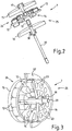
- Figure 2 illustrates a variant of the actuator 7 according to the invention, wherein first coils 13 and second coils 14 are arranged on two opposite sides of a carrier plate 12.
- the carrier plate 12 is also designed as a printed circuit board 29 or board 29.
- the actuator 7 according to Figure 2 has a different number of first coils 13 and second coils 14, ie fewer second coils 14 are present here than first coils 13.
- a first motor 24 has a greater torque and / or a greater output and / or a higher rotational speed than a second motor 24 of the actuator 7.
- the actuator 6 according to FIG Figure 1 advantageously comprises two actuators which can be driven or actuated separately or (essentially) independently by the first motor 13 and on the other hand by the second motor 14.
- the coils 13, 14 or the coil cores of the coils 13, 14, not shown in the interior thereof, are directly mounted / fixed.
- a first motor 24 essentially comprises the carrier plate 12 or the circuit board 29, the first coils 13, a first rotor 15, magnets 23, in particular permanent magnets 23, and preferably a gear / drive wheel 17 or a drive shaft 17
- a second motor 14 essentially comprises the carrier plate 12 or circuit board 29, the second coils 14, a second rotor 16, magnets 23, in particular permanent magnets 23, and preferably a gear / drive wheel 18 or a drive shaft 18.
- the control unit includes, for example, a chip or microprocessor or electrical. Components such as resistors, capacitors or the like.
- the circuit board 29 is equipped or also includes the control unit in the subsequent variants of the invention.
- the sleeve 19 advantageously defines the distance and the position / orientation of the two rotors 15, 16 and, together with the axis 20, forms the sliding / mounting of the rotors 15, 16 (cf. also Figures 3 to 7 ).
- the axis 20 is, for example, firmly fixed / positioned on an actuator housing or the like, so that the axes of rotation of the two rotors 15, 16 or motors 24, 25 are exactly fixed / positioned.
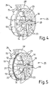
- FIG. 2 to 7 Different variants of the actuators 7 or electric motors 7 according to the invention are shown schematically. In contrast to the variant, however, this is Figure 2 a carrier plate 12 separate from the board 29 is provided. The carrier plate 12 is advantageously firmly connected or screwed to the circuit board 29 (without a more detailed illustration). In addition, various electrical connections or cables or the like are present between the carrier plate 12 and the circuit board 29, for example coil ends of the coils 13, 14 soldered to the circuit board 29.
- first coils 13 and the second coils 14 are in accordance with Figure 3 different (large) dimensions.
- the latter can generally be implemented, for example, with a different number of windings and / or differently thick / thick coil or copper wires or coils 13, 14 with different lengths and / or widths and / or heights.
- the variant according to Figure 4 the same number of first and second coils 13, 14, for example 12 pieces each.
- the second coils 14 are dimensioned significantly smaller than the first coils 13, in particular with regard to the width or windings / wire diameter of the respective coils 13, 14.
- the different (large) dimensioning of the motors 24, 25 or stators can also be achieved according to the invention by different inner and / or outer diameters of the circular ring or coil ring.
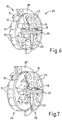
- second coil 14 which form a circular ring which has a significantly smaller outer diameter than the outer diameter of the circular ring of the first coils 13 on the other side of the carrier plate 12.
- the number of coils is the same in this example, for example twelve pieces per side.
- the carrier plate 12 or the circuit board 12 or circuit board 12 according to FIG Figure 2 layered or as a structural unit with, for example, two shielding elements 21, 22 or metal layers 21, 22 or so-called short-circuit plates 21, 22.
Landscapes
- Engineering & Computer Science (AREA)
- General Engineering & Computer Science (AREA)
- Mechanical Engineering (AREA)
- Chemical & Material Sciences (AREA)
- Combustion & Propulsion (AREA)
- Power Engineering (AREA)
- Connection Of Motors, Electrical Generators, Mechanical Devices, And The Like (AREA)
- Actuator (AREA)
- Fluid-Driven Valves (AREA)
- Valve Device For Special Equipments (AREA)
Abstract
Description
- Die Erfindung betrifft einen Stellantrieb für ein Stellorgan zur Steuerung eines Fluides, insb. eines Kühlmittels eines Fahrzeugs, wobei wenigstens ein erster, elektrischer Antriebsmotor zumindest eine erste, um eine erste Drehachse drehbare Rotoreinheit und eine erste, zumindest zwei erste Antriebsspulen umfassende Statoreinheit aufweist, wobei eine elektrische und/oder elektronische Leiterplatte wenigstens eine elektrische und/oder elektronische Kontrolleinheit zum Kontrollieren des ersten Antriebsmotors umfasst, nach dem Oberbegriff des Anspruchs 1.
- Moderne Fahrzeugmotoren, insb. Verbrennungskraftmaschinen wie z.B. Viertaktmotoren, oder Elektromotoren insb. auch mit Brennstoffzellen zusammen, in Fahrzeugen wie PKWs oder LKWs werden bis auf wenige Ausnahmen flüssigkeitsgekühlt bzw. mit Wasser temperiert/erwärmt, wobei in der Regel ein Gemisch aus Wasser und einem Frost- und Korrosionsschutzmittel als Kühlflüssigkeit als sog. Kühlwasser dient.
- Ein Wasser- bzw. Kühlmittelkühler, der sog. "Kühler", bzw. Wärmetauscher ist meist an der Front des Fahrzeuges angebracht, wo ein Luftstrom das durchfließende Kühlmittel abkühlt. Von dort wird das Kühlmittel mit einer Kühlmittelpumpe über Schläuche durch den Motor gepumpt (Zylinderkopf und Motorblock). Thermisch stark beanspruchte Anbauteile des Motors wie Abgasturbolader, Generator oder der Abgasrückführkühler können mit in den Kühlmittelkreislauf eingebunden sein. In modernen Motoren werden häufig elektrische Kühlmittelpumpen (Leistung ∼ 200 W) mit regelbarer Förderleistung eingesetzt. Sie haben eine wesentlich geringere Leistungsaufnahme als mechanisch angetriebenen Pumpen und ermöglichen dadurch einen geringeren Kraftstoffverbrauch.
- Der Kühlkreislauf, und damit die Motortemperatur, wird u.a. durch ein Stellorgan geregelt, früher üblicherweise ein Thermostat, das heute zum Teil bereits durch ein Drehschieber ersetzt wird. Letzteres ist aktiv regelbar, insb. über die Fahrzeugelektronik bzw. einen Elektromotorantrieb.
- Solange der Motor nicht seine Betriebstemperatur erreicht hat, ist das Stellorgan/Thermostatventil geschlossen, und die Kühlflüssigkeit zirkuliert meist nur über Motor, Wasserpumpe und Heizungswärmeübertrager. Öffnet das Stellorgan bzw. der Thermostat, so wird der Haupt-Wasserkühler mit in den Kreislauf eingeschlossen, und die eigentliche Kühlung setzt ein. Das Stellorgan/Thermostatventil öffnet je nach Fahrzeug und Motor üblicherweise zwischen ca. 75°C und ca. 88°C. Es gibt mittlerweile zunehmend auch Motoren mit mehreren Kreisläufen, die unterschiedlichste Temperaturen aufweisen, und auch kennfeldgesteuerte elektrische Stellorgane bzw. Thermostate.
- Da sich die Kühlflüssigkeit bei Erwärmung ausdehnt, steigt der Druck im Kühlsystem. Um diesen Effekt auszugleichen, ist ein Ausgleichsbehälter/Ausdehnungsgefäß in den Kühlkreislauf integriert, der das überschüssige Kühlmittel aufnimmt und bei Bedarf wieder abgibt. Durch das Erhöhen des Systemdruckes steigt gleichzeitig der Siedepunkt des Kühlmittels.
- Das zuvor genannte Motorkühlsystem ist nicht immer das einzige Kühlsystem in einem Motor bzw. Fahrzeug. Zusätzlich können noch separate Systeme z.B. für die Ladeluft, das Motoröl, das Getriebeöl, das Lenkgetriebeöl und/oder den Kraftstoff eingebaut sein. Bei Hybridfahrzeugen existiert meist ein weiteres Kühlsystem zur Kühlung von Elektromotoren/Generatoren und deren Leistungselektronik, z.B. Inverter, Umrichter, etc..
- Oft sind die Pumpe und das Stellorgan in einem gemeinsamen Gehäuse untergebracht und direkt am Motor, insb. Zylinderkopf, fixiert, wobei üblicherweise der Zylinderkopf das Gegenstück bzw. das zweite Gehäuseelement zu einem Kühlmittelgehäuseelement bildet und der Antrieb der Kühlmittelpumpe über den Motor bzw. die Nockenwelle mit Zahnriemen erfolgt. Auch sind vom Motor separate Pumpgehäuse im Einsatz, wobei meist ein separater Elektromotor als Antrieb der Kühlmittelpumpe verwendet wird.
- Diese Baueinheit, ob separat oder direkt an den Motor/Zylinderkopf angeflanscht, wird auch als sog. Kühlmittelregeleinheit oder Kühlmittelverteilermodul bezeichnet und weist als zentrale Komponenten die Kühlmittelpumpe sowie das Stellorgan auf, insb. Drehschieber oder einen oder zwei Thermostate. Zur Verteilung bzw. Steuerung/Regelung der o.g. verschiedensten Kühlmittelströme bzw. Teilkreisläufe sind diverse Kühlkanäle und Anschlüsse bzw. Öffnungen für das Kühlwasser/-mittel integriert. Als Material wird vielfach Metall, insb. Aluminium, oder Kunststoff, insb. sog. Hochleistungskunststoffe, eingesetzt.
- Es ist jedoch von Nachteil, dass die unterschiedlichsten Kühlmittelströme bzw. Teilkreisläufe und diverse Kühlkanäle sowie Anschlüsse bzw. Öffnungen bislang nur bedingt separat regelbar sind oder nur mit einem sehr großen konstruktiven Aufwand. So sind z.B. zwei Thermostate einerseits aufwändig bei der Herstellung des Moduls und benötigen relativ viel Platz.
- Andererseits sind diese Thermostate nicht aktiv regelbar und somit nicht an unterschiedlichste Betriebsbedingungen des Verbrennungsmotors bzw. Fahrzeug exakt/flexibel anpassbar.
- Auch besteht im Laufe des (langjährigen) Betriebs die Gefahr der Undichtigkeit durch die diversen Anschlussstellen der Thermostate bzw. Stellorgane und/oder Durchbrüche für die außen am Modul angeordneten Antreibe für den Drehschieber bzw. das Stellorgan oder die Pumpe etc..
- Als Stellantrieb für einen derartigen Drehschieber bzw. das Stellorgan wird u.a. ein Elektromotor mit Rotor und Stator verwendet. Dieser Elektromotor wird elektrisch bzw. elektronisch gesteuert und damit auch das Stellorgan. Üblicherweise wird eine Platine bzw. elektrische und/oder elektronische Leiterplatte mit dieser Steuer- bzw. Kontrolleinheit bestückt bzw. ausgestattet.
- Aufgabe der Erfindung ist es demgegenüber, einen Stellantrieb für ein Stellorgan zur Steuerung eines Fluides, insb. eines Kühlmittels bzw. flüssigen Wärmeträgers eines Fahrzeugs, der eingangs genannten Art vorzuschlagen, der neue und/oder zusätzliche Funktionalitäten realisieren und/oder platzsparend umgesetzt werden kann und der insbesondere wirtschaftlich günstig herstellbar ist.
- Diese Aufgabe wird, ausgehend von einem Stellantrieb der einleitend genannten Art, durch die Merkmale des Anspruchs 1 gelöst. Durch die in den Unteransprüchen genannten Maßnahmen sind vorteilhafte Ausführungen und Weiterbildungen der Erfindung möglich.
- Dementsprechend zeichnet sich ein erfindungsgemäßer Stellantrieb dadurch aus, dass wenigstens auf einer ersten Seite einer Trägerplatte zumindest die zwei ersten Antriebsspulen der ersten Statoreinheit und auf einer zweiten, der ersten Seite der Trägerplatte gegenüberliegend angeordneten, zweiten Seite der Trägerplatte zumindest zwei zweite Antriebsspulen einer zweiten Statoreinheit eines zweiten elektrischen Antriebsmotors angeordnet sind, wobei der zweite elektrische Antriebsmotor die zweite Statoreinheit und eine zweite Rotoreinheit umfasst.
- Mit Hilfe dieser Maßnahme wird erreicht, dass der Stellantrieb besonders platzsparend bzw. relativ klein ausgeführt werden kann und zudem noch neue bzw. erweitere Funktionalitäten realisiert werden können. So können mit den zwei elektrischen Antriebsmotoren zwei separate Funktionalitäten bzw. Betätigungen von zwei Stellgliedern verwirklicht werden. Hiermit ergeben sich neue und erweitere Möglichkeiten bei der Steuerung des Fluides, insb. in Bezug auf die Steuerung eines flüssigen Wärmeträgers bzw. des Kühlmittels eines Fahrzeugmotors wie Verbrennungsmotor oder Elektromotor mit diversen Motorkomponenten und/oder der Akkumulatoren für einen Elektromotorantrieb und/oder einer Brennstoffzelle für den Elektromotorantrieb.
- Beispielsweise können die beiden Antriebsmotoren unabhängig voneinander betrieben werden. Drehzahl, Drehmoment und/oder Drehrichtung und auch die gemäß der Erfindung individuell abgestimmt und/oder angesteuert bzw. kontrolliert werden.
- Vorzugsweise weist/weisen der/die erste und/oder zweite Rotoreinheit (jeweils) mehrere Permanentmagnete auf, insb. Magnete mit sog. Seltenen Erden. Hierdurch kann eine besonders kompakte und/oder vergleichsweise leistungsstarke Bauweise des Stellantriebs verwirklicht werden. Auch wird der Aufwand für die Ansteuerung bzw. den Betrieb durch die Verwendung von Permanentmagneten minimiert.
- Vorteilhafterweise ist die Trägerplatte als Spulenkern, insbesondere Ferritkern, der ersten Antriebsspulen und/oder der zweiten Antriebsspulen ausgebildet. Hiermit kann eine Doppelfunktion, nämlich eine Träger- und eine magnetische Funktion, realisiert werden, was den konstruktiven und wirtschaftlichen Aufwand reduziert.
- Beispielsweise ist der Spulenkern als Sinterkern verwirklicht. Das bedeutet, dass der Spulenkern aus Sintermaterial hergestellt ist. Hiermit können nahezu beliebige Formen, insb. auch komplexe Geometrien ohne großen Aufwand kostengünstig hergestellt werden. So kann die Trägerplatte in vorteilhafter Weise alle Spulenkerne der ersten und/oder zweiten Antriebsspulen umfassen. Hierdurch ist eine einstückige Baueinheit als Trägerplatte mit Spulenkernen realisierbar.
- In einer vorteilhaften Variante der Erfindung weist die Trägerplatte einen Schichtaufbau bzw. wenigstens zwei Trägerschichten auf. Beispielsweise umfasst eine erste Trägerschicht wenigstens die ersten Antriebsspulen und/oder eine zweite Trägerschicht umfasst die zweiten Antriebsspulen. So können die Trägerschichten in vorteilhafter Weise miteinander verbunden/fixiert, insb. verklebt oder verlötet, werden. Auch kann eine Zwischenschicht, insb. eine Abschirmung bzw. eine Abschirmschicht oder dergleichen, vorgesehen werden und insb. zwischen den wenigstens zwei bzw. der ersten und der zweiten Trägerschicht/en angeordnet werden.
- Vorteilhafterweise ist die Leiterplatte als die Trägerplatte ausgebildet und/oder umfasst die Trägerplatte die Leiterplatte. Hiermit kann die Leiterplatte eine Doppelfunktion verwirklichen, was den Aufwand wesentlich reduziert. Zum Beispiel können Spulenkerne der ersten und/oder zweiten Antriebsspulen, insb. als Sinterkerne verwirklicht, auf der Leiterplatte/Platine montiert bzw. fixiert werden. So können die ersten und/oder zweiten Antriebsspulen mit den jeweiligen Spulenkernen als einstückige erste und/oder zweite Montageeinheit auf der jeweiligen Seite der Leiterplatte/Platine befestigt bzw. elektrisch angeschlossen werden. Dies reduziert den Herstellungsaufwand.
- Beispielsweise wird die Leiterplatte/Platine mit den ersten und/oder zweiten Antriebsspulen und/oder deren Spulenkernen bestückt. Dies kann wirtschaftlich günstig verwirklicht werden und ist zudem sehr platzsparend.
- Vorteilhafterweise ist die Kontrolleinheit und/oder die ersten Antriebsspulen und/oder die zweiten Antriebsspulen und/oder Spulenkerne der Antriebsspulen und/oder erste Trägerschicht und/oder zweite Trägerschicht als Bestückung der Leiterplatte/Platine ausgebildet. So sind diese vorgenannten Bauteile entsprechend einzeln oder im Verbund auf/mit der Leiterplatte bzw. der Trägerplatte fest verbunden und/oder verdrahtet bzw. verlötet. Hierdurch können diese Bauteile mit bereits vorhandenen Fertigungsverfahren montiert werden, was besonders wirtschaftlich günstig ist. Die ersten und/oder zweiten Antriebsspulen können mit oder ohne (Ferrit-)Kerne bzw. Spulenkerne in vorteilhafter Weise jeweils als Einzelspulen oder als sog. kombinierte Kerne oder auch als auf die Leiterplatte gedruckte Spulen/Schaltungen ausgebildet werden.
- Generell ist von Vorteil, die ersten Antriebsspulen gemeinsam bzw. konzentrisch um die erste Drehachse und die zweiten Antriebsspulen gemeinsam bzw. konzentrisch um eine zweite Drehachse anzuordnen.
- In einer besonderen Weiterbildung der Erfindung ist die erste Drehachse der ersten Rotoreinheit zugleich eine zweite Drehachse der zweiten Rotoreinheit, so dass der erste elektrische Antriebsmotor konzentrisch zum zweiten elektrischen Antriebsmotor angeordnet ist. Hiermit wird der Stellantrieb noch kompakter bzw. platzsparender. Zudem kann in vorteilhafter Weise eine (gemeinsame/einzige) Ausnehmung/Durchbruch bzw. ein Loch in der Leiterplatte als Durchgang/Durchlass für eine Antriebswelle oder Antriebsachse des/der beiden Antriebsmotoren verwendet werden. Gegebenenfalls kann mit dieser Maßnahme auch eine vorteilhafte Fixierung und/oder Positionierung der beiden Rotoreinheiten bzw. der Antriebswellen oder Antriebsachsen erreicht werden.
- In einer vorteilhaften Variante der Erfindung ist/sind wenigstens eine erste Antriebswelle des ersten elektrischen Antriebsmotors wenigstens teilweise als erste Hohlwelle und/oder wenigstens eine zweite Antriebswelle des zweiten elektrischen Antriebsmotors wenigstens teilweise als zweite Hohlwelle ausgebildet, wobei eine Antriebsachse als Lagerelement der ersten und/oder zweiten Hohlwelle ausgebildet ist, so dass die erste und/oder zweite Hohlwelle um die Antriebsachse drehbar ist/sind. Hiermit wird/werden die erste und/oder zweite Rotoreinheit in vorteilhafter Weise gelagert, z.B. mittels Gleitlagerung, bzw. positioniert und insbesondere konzentrisch zueinander ausgerichtet. Dies verbessert die Laufruhe bzw. auch die Konzentrizität der beiden Antriebsmotoren.
- Vorteilhafterweise ist wenigstens eine Abschirmeinheit zum elektromagnetischen Abschirmen des/der ersten Antriebsmotors/Statoreinheit von dem/der zweiten Antriebsmotor/Statoreinheit vorgesehen. Diese Maßnahme verbessert den unabhängigen bzw. individuellen Betrieb der beiden Antriebsmotoren, da diese sich durch die Abschirmung nicht bzw. nur sehr wenig gegenseitig beeinflussen können.
- Gegebenenfalls kann eine unterschiedliche Bestromung der Antriebsspulen als Abschirmung bzw. Kompensation der beiden Statoreinheiten/Antriebsmotoren vorgesehen werden, so dass die gegenseitige Beeinflussung reduziert bzw. minimiert wird.
- Vorzugsweise umfasst die Leiterplatte wenigsten ein Abschirmelement der Abschirmeinheit. Beispielsweise ist das Abschirmelement als Kurzschlussblech, Metallfolie oder dergleichen ausgebildet. Beispielsweise weist die Leiterplatte einen Schichtaufbau auf, wobei wenigstens ein Abschirmelement als Abschirmschicht in/auf der Leiterplatte angeordnet ist/sind.
- Auch kann die gegenseitige Beeinflussung dadurch reduziert bzw. minimiert werden, dass in vorteilhafter Weise die Anzahl der ersten Antriebsspulen nicht gleich der Anzahl der zweiten Antriebsspulen ist und/oder dass in radialer Richtung um die Drehachse betrachtet die ersten Antriebsspulen wenigstens teilweise versetzt zu den zweiten Antriebsspulen angeordnet sind. Beispielsweise sind in radialer Richtung um die Drehachse betrachtet die ersten Antriebsspulen wenigstens in einem ersten Kreisbogensegment/-sektor und die zweiten Antriebsspulen in einem in Bezug auf das erste Kreissektor versetzt angeordneten, zweiten Kreisbogensegment/-sektor angeordnet sind. Gegebenenfalls sind die Spulen der beiden Motoren in radialer Richtung betrachtet jeweils auf unterschiedlichen Hälften angeordnet.
- Vorteilhafterweise ist ein erster Abstand der ersten Antriebsspulen in radialer Richtung zur Drehachse betrachtet nicht gleich einem zweiten Abstand der zweiten Antriebsspulen und/oder ist ein erster, auf die erste Drehachse bezogener Außendurchmesser der ersten Antriebsspulen nicht gleich einem zweiten, auf die zweite Drehachse bezogener Außendurchmesser der zweiten Antriebsspulen. Das bedeutet, dass die Antriebsspulen der beiden Motoren unterschiedlich groß ausgeführt werden können, um v.a. ein gegenseitiges Beeinflussen zu reduzieren. Hierbei können auch unterschiedliche Drehmomente bzw. Leistungen der beiden Motoren verwirklicht werden, womit unterschiedliche Stellglieder betätig bzw. beaufschlagt werden können.
- Auch können auch unterschiedliche Lasten, die unterschiedliche Stellglieder generieren, zu einer Reduzierung der gegenseitigen Beeinflussung der beiden Antriebsmotoren führen.
- Vorteilhafterweise sind wenigstens ein erstes Betätigungselement zum Betätigen eines ersten Stellgliedes und ein zweites Betätigungselement zum Betätigen eines zweiten Stellgliedes vorgesehen, wobei das erste Betätigungselement zwischen dem ersten Antriebsmotor und dem ersten Stellglied angeordnet und das zweite Betätigungselement zwischen dem zweiten Antriebsmotor und dem zweiten Stellglied angeordnet sind.
- Vorzugsweise ist das erste Betätigungselement wenigstens teilweise als Hohlwelle und/oder das erste Betätigungselement wenigstens teilweise als Welle ausgebildet ist/sind, wobei die Welle als Lagerelement der Hohlwelle ausgebildet ist, so dass die Hohlwelle um die Welle drehbar ist.
- Vorteilhafterweise umfasst das Stellorgan wenigstens ein erstes Stellglied und ein zweites Stellglied, wobei insbesondere ein erstes Betätigungselement zum Betätigen des ersten Stellglieds konzentrisch zu einem zweiten Betätigungselement zum Betätigen des zweiten Stellglieds angeordnet ist, so dass das erste Betätigungselement und das zweite Betätigungselement eine gemeinsame Längsachse und/oder Drehachse aufweisen. Mit Hilfe dieser Maßnahme wird erreicht, dass die Motorkühleinheit besonders platzsparend bzw. relativ klein ausgeführt werden kann und zudem noch neue bzw. erweitere Funktionalitäten realisiert werden können.
- So können mit den zwei Stellgliedern des Stellorgans mindestens zwei separate Funktionalitäten bzw. Kühlfunktionen verwirklicht werden. Hiermit ergeben sich neue und erweitere Möglichkeiten bei der Steuerung des Kühlfluides, insb. in Bezug auf die Steuerung des Kühlmittels eines Fahrzeugmotors mit diversen Motorkomponenten. Dementsprechend können unterschiedliche Komponenten unterschiedlich gekühlt werden und somit unterschiedliche Betriebstemperaturen aufweisen. Beim Einsatz für ein Verbrennungsmotor, insbesondere in einem Fahrzeug, kann in vorteilhafter Weise das Motoröl weniger wie andere Komponenten des Motors gekühlt werden, so dass das Motoröl etwas wärmer und somit dünnflüssiger ist. Hierdurch kann der Motor leichter laufen und somit kann Energie gespart werden.
- Beispielsweise können die beiden Stellglieder unabhängig voneinander betrieben werden. Durchflussmengen und/oder Öffnungsquerschnitte des jeweiligen Kanals können gemäß der Erfindung individuell und betriebsabhängig eingestellt und/oder verändert bzw. kontrolliert werden. Entsprechend können neue Betriebsbedingungen verwirklicht werden.
- Darüber hinaus ist lediglich ein gemeinsamer Durchgang bzw. Ausnehmung in der Motorkühleinheit notwendig, um die beiden Stellglieder zu betätigen bzw. anzutreiben. Hiermit reduziert sich der konstruktive als auch der dichtungstechnische und somit der wirtschaftliche Aufwand. Dies minimiert auch die Gefahr bzgl. dem Auftreten von Undichtigkeiten im Laufe des langjährigen Betriebs.
- Beispielsweise kann/können das/die erste und/oder zweite Stellglied längs der Längsachse verstellt bzw. verschoben werden. Vorteilhafterweise ist/sind das erste Betätigungselement und/oder das zweite Betätigungselement drehbar um die Drehachse. Die Abdichtung und somit die Zuverlässigkeit des Durchgangs der Betätigung des Stellorgans durch das Gehäuse der Motorkühleinheit hindurch ist bei einer rotatorischen Verstellung des/der Stellglieder wesentlich vereinfacht bzw. verbessert.
- Vorteilhafterweise ist wenigstens eine (erste und/oder zweite) Getriebevorrichtung zum Übersetzen/Untersetzen des ersten und/oder zweiten Antriebsmotors vorgesehen. So sind in vorteilhafter Weise die erste Getriebevorrichtung zwischen dem ersten Antriebsmotor und dem ersten Stellglied/Betätigungselement und die zweite Getriebevorrichtung zwischen dem zweiten Antriebsmotor und dem zweiten Stellglied/Betätigungselement anzuordnen. Hiermit können z.B. unterschiedliche Drehzahlen und/oder Drehmomente bzw. eine vorteilhafte Anpassung dieser Parameter an das jeweilige Stellglied bzw. Antriebsmotor verwirklicht werden.
- Ein bevorzugtes Ausführungsbeispiel der Erfindung ist in der Zeichnung dargestellt und wird anhand der Figuren nachfolgend näher erläutert.
- Im Einzelnen zeigt:
- Figur 1
- schematisch ein Motorkühlsystem eines Fahrzeugs mit einem Stellantrieb gemäß der Erfindung,
- Figur 2
- eine schematische Explosionsdarstellung eines ersten Stellantriebs gemäß der Erfindung,
- Figur 3
- eine schematische, teilweise geschnittene, perspektivische Darstellung eines zweiten Stellantriebs gemäß der Erfindung,
- Figur 4
- eine schematische, teilweise geschnittene, perspektivische Darstellung eines dritten Stellantriebs gemäß der Erfindung,
- Figur 5
- eine schematische, teilweise geschnittene, perspektivische Darstellung eines vierten Stellantriebs gemäß der Erfindung,
- Figur 6
- eine schematische, teilweise geschnittene, perspektivische Darstellung eines fünften Stellantriebs gemäß der Erfindung und
- Figur 7
- eine schematische, teilweise geschnittene, perspektivische Darstellung eines sechsten Stellantriebs gemäß der Erfindung.
- In
Figur 1 ist eine Verteilereinheit/-modul 4 mit einigen Komponenten eines Wärme- bzw. Kühlsystems eines Fahrzeugs schematisch dargestellt. So wird ein Motor 1, insb. Verbrennungsmotor oder Elektromotor, mittels Kühlwasser gekühlt. Es kann eine Ölkühlung mittels einem Motorölkühler 2 und einem Getriebeölkühler 3 vorgesehen werden. - An einem nicht näher dargestellten Motorblock bzw. an einem Zylinderkopf ist das Verteilermodul 4 angeordnet bzw. angeflanscht und eine Kühlmittelpumpe 5 wird z.B. über den Motor 1 bzw. dessen Nockenwelle und Riemen oder dergleichen angetrieben. In diesem kann entgegen der in
Figur 1 dargestellten Variante auch die Kühlmittelpumpe 5 integriert werden. - Das Verteilermodul 4 umfasst ein in
Figur 1 sehr schematisch dargestelltes Stellorgan 6, insb. ein Drehschieber 6 oder dergleichen ist. Das Stellorgan 6 wird mittels einem Stellantrieb 7, insb. einem Elektromotor 7, der mittels einer Kontrolleinheit und wenigstens teilweise in Verbindung mit einer sog. "Boardelektronik" kontrolliert bzw. gesteuert. Hiermit kann eine vorteilhafte kennliniengesteuerte Regelung des Kühlsystems verwirklicht werden. Diverse Sensoren, insb. Temperatursensoren, Drucksensoren oder dergleichen unterstützen die Steuerung. - Die Kühlmittelpumpe 5 pumpt das Kühlwasser in den vorhandenen Kühlkreisläufen u.a. zwischen einem sog. Kühler 28 bzw. einem Hauptwärmetauscher 28 und einem Ausgleichsbehälter 9 sowie der Motorkühlung/Ölkühlung 2 sowie einem Heizungswärmetauscher 10 und ggf. weiteren Komponenten 30 hindurch.
- Darüber hinaus kann auch im Fall einer Aufladung des Abgases bzw. einer Turbo-/Kompressorladung auch ein Abgaswärmetauscher 8 bzw. ein Ladeluftkühler oder weitere Komponenten 30 vorgesehen/eingebunden werden.
- Im Fall eines Fahrzeugantriebs mit Elektromotor 1 und Akkumulator/Traktionsbatterie sowie ggf. einer Brennstoffzelle zur Stromerzeugung kann auch der Elektromotor 1 z.B. auf eine optimale Betriebstemperatur und die Batterie auf eine andere Betriebstemperatur sowie die Brennstoffzelle auf eine höhere Betriebstemperatur temperiert bzw. gekühlt werden.
- In
Figur 1 wird deutlich, dass der gesamte Kühlkreislauf somit mehrere Teilkreisläufe umfasst, die unterschiedliche Temperaturen/Temperaturniveaus aufweisen und die im Wesentlichen mittels dem Verteilergehäusemodul 4 bzw. Pumpe 5 und Stellorgan 6 gesteuert/kontrolliert/verteilt werden. Das bedeutet, dass die unterschiedlichen Betriebstemperaturen mittels des Moduls 4 bzw. des Stellorgans 6 durch vorteilhafte Fluidkontrolle/-steuerung realisiert werden. - Das Verteilergehäusemodul 4 kann separat vom Motor 1 angeordnet werden, wobei dieses dann vorzugsweise zwei Gehäuseelemente und den Elektroantrieb 7 als erfindungsgemäßen Stellantrieb 7 umfasst.
-
Figur 2 verdeutlicht eine Variante des Stellantriebs 7 gemäß der Erfindung, wobei erste Spulen 13 und zweite Spulen 14 auf zwei gegenüberliegenden Seiten einer Trägerplatte 12 angeordnet sind. Bei dieser Variante der Erfindung ist die Trägerplatte 12 zugleich als Leiterplatte 29 bzw. Platine 29 ausgebildet. - Der Stellantrieb 7 gemäß
Figur 2 weist eine unterschiedliche Anzahl an ersten Spulen 13 und zweiten Spulen 14 auf, d.h. hier sind weniger zweite Spulen 14 als erste Spulen 13 vorhanden. So weist z.B. bei gleicher oder vergleichbarer Bestromung ein erster Motor 24 ein größeres Drehmoment und/oder eine größere Leistung und/oder eine größere Drehgeschwindigkeit als ein zweiter Motor 24 des Stellantriebes 7 auf. Hierdurch können z.B. zwei unterschiedliche Stellglieder in vorteilhafter Weise betreiben werden, wobei das Stellorgan 6 gemäßFigur 1 in vorteilhafter Weise zwei Stellglieder umfasst, die einerseits vom ersten Motor 13 und andererseits vom zweiten Motor 14 separat bzw. (im Wesentlichen) unabhängig angetrieben bzw. betätigt werden können. - Bei der o.g. Variante sind auf der Leiterplatte 29 bzw. Platine 29, d.h. hier auf der Trägerplatte 12 gemäß der Erfindung, direkt die Spulen 13, 14 bzw. in deren Innern nicht näher dargestellte Spulenkerne der Spulen 13, 14 montiert/fixiert.
- Grundsätzlich umfasst gemäß der Erfindung ein erster Motor 24 im Wesentlichen die Trägerplatte 12 bzw. die Platine 29, die ersten Spulen 13, ein erster Rotor 15, Magnete 23, insb. Permanentmagnete 23, und vorzugsweise ein Zahnrad/Antriebsrad 17 bzw. eine Antriebswelle 17. Entsprechend umfasst ein zweiter Motor 14 im Wesentlichen die Trägerplatte 12 bzw. Platine 29, die zweiten Spulen 14, ein zweiter Rotor 16, Magnete 23, insb. Permanentmagnete 23, und vorzugsweise ein Zahnrad/Antriebsrad 18 bzw. eine Antriebswelle 18.
- Gemäß der Erfindung ist die (einstückige) Trägerplatte 12 bzw. Platine 29 mit den ersten Spulen 13 sowie den zweiten Spulen 14 sowie einer nicht näher dargestellten Kontrolleinheit zum Kontrollieren bzw. Steuern/Betreiben der beiden Motoren 24, 25 bestückt bzw. verlötet. Die Kontrolleinheit umfasst z.B. einen Chip bzw. Mikroprozessor oder elektr. Bauteile wie z.B. Widerstände, Kondensatoren oder dergleichen auf. Die Platine 29 ist bestückt bzw. umfasst auch bei den nachfolgenden Varianten der Erfindung die Kontrolleinheit.
- Darüber hinaus weist die in
Figur 2 dargestellte Variante eine (feststehende) Achse 20 und eine Hülse 19 auf, um die sich die Rotoren 15, 16 mit den Zahnrädern 17, 18 drehen. Die Hülse 19 definiert in vorteilhafter Weise den Abstand sowie die Lage/Ausrichtung der beiden Rotoren 15, 16 und bildet gemeinsam mit der Achse 20 die Gleit-/Lagerung der Rotoren 15, 16 (vgl. auchFiguren 3 bis 7 ). Die Achse 20 ist beispielsweise an einem Stellantriebsgehäuse oder dergleichen fest fixiert/positioniert, so dass die Drehachsen der beiden Rotoren 15, 16 bzw. Motoren 24, 25 exakt festgelegt/positioniert sind. - In den
Figuren 2 bis 7 sind verschiedene Varianten der Stellantriebe 7 bzw. Elektromotoren 7 gemäß der Erfindung schematisch dargestellt. Hierbei ist jedoch im Unterschied zur Variante gemäßFigur 2 eine zur Platine 29 separate Trägerplatte 12 vorgesehen. Die Trägerplatte 12 ist in vorteilhafter Weise mit der Platine 29 fest verbunden bzw. verschraubt (ohne nähere Darstellung). Zudem sind diverse elektrische Verbindungen bzw. Kabel oder dergleichen zwischen der Trägerplatte 12 und der Platine 29 vorhanden, z.B. auf der Platine 29 verlötete Spulenenden der Spulen 13, 14. - Es weist der Stellantrieb 7 gemäß
Figur 3 unterschiedliche erste Spulen 13 und zweite Spulen 14 auf, wobei diese einerseits in radialer Richtung versetzt zueinander angeordnet sind. Hiermit wird die gegenseitige elektromagnetische Beeinflussung der Spulen 13, 14 in vorteilhafter Weise reduziert. - Andererseits sind die ersten Spulen 13 sowie die zweiten Spulen 14 gemäß
Figur 3 unterschiedlich (groß) dimensioniert. Letzteres kann generell z.B. mit einer unterschiedlichen Anzahl an Wicklungen und/oder unterschiedlich starken/dicken Spulen- bzw. Kupferdrähten oder Spulen 13, 14 mit unterschiedlicher Länge und/oder Breite und/oder Höhe realisiert werden. So weist die Variante gemäßFigur 4 zwar gleich viele erste und zweite Spulen 13, 14 auf, z.B. jeweils 12 Stück. Jedoch sind die zweiten Spulen 14 deutlich kleiner dimensioniert als die ersten Spulen 13, insb. bzgl. der Breite bzw. Wicklungen/Drahtdurchmesser der jeweiligen Spulen 13, 14. - Es ist generell gemäß der Erfindung von Vorteil, die Spulen 13, 14 in vorteilhafter Weise in einem Kreisring anzuordnen. Grundsätzlich ist von Vorteil, die Spulen 13, 14 jeweils konzentrisch und/oder scheibenförmig auf einer Ebene bzw. der Platine 29 bzw. der Trägerplatte 12 anzuordnen.
- Die unterschiedlich (große) Dimensionierung der Motoren 24, 25 bzw. Statoren kann gemäß der Erfindung auch durch unterschiedliche Innen- und/oder Außendurchmesser des Kreisrings bzw. Spulenrings verwirklicht werden. So weist die Variante gemäß
Figur 7 z.B. zweite Spule 14 auf, die einen Kreisring bilden, der einen deutlich kleineren Außendurchmesser aufweist als der Außendurchmesser des Kreisrings der ersten Spulen 13 auf der anderen Seite der Trägerplatte 12. Die Anzahl der Spulen ist in diesem Beispiel gleich, beispielsweise zwölf Stück je Seite. - Dagegen sind bei der Variante gemäß
Figur 6 wiederum zwölf erste Spulen 13, jedoch nur sechs zweite Spulen 14 auf der anderen Seite der Trägerplatte 12 angeordnet. Dementsprechend unterschiedliche Motorparameter, z.B. Drehmoment, Drehzahl und/oder Drehgeschwindigkeit etc., werden hierdurch in vorteilhafter Weise realisiert. Auch kann hiermit eine gegenseitige Beeinflussung verringert bzw. eine gewisse Abschirmung der beiden Motoren 24, 25 verwirklicht werden. - Eine besonders vorteilhafte Reduktion der gegenseitigen Beeinflussung bzw. eine vorteilhafte Abschirmung zwischen den beiden Motoren 24, 25 kann mit der Variante gemäß
Figur 5 verwirklicht werden. So kann die Trägerplatte 12 oder nicht näher dargestellt die Leiterplatte 12 bzw. Platine 12 gemäßFigur 2 schichtartig bzw. als Baueinheit mit z.B. zwei Abschirmelementen 21, 22 bzw. Metallschichten 21, 22 bzw. sog. Kurzschlussbleche 21, 22 ausgebildet werden. -
- 1.
- Motor
- 2.
- Motorölkühler
- 3.
- Getriebeölkühler
- 4.
- Modul
- 5.
- Pumpe
- 6.
- Drehschieber
- 7.
- Antrieb
- 8.
- Abgaswärmetauscher
- 9.
- Behälter
- 10.
- Wärmetauscher
- 11.
- Gehäuseelement
- 12.
- Trägerplatte
- 13.
- Spulen
- 14.
- Spulen
- 15.
- Rotor
- 16.
- Rotor
- 17.
- Zahnrad
- 18.
- Zahnrad
- 19.
- Hülse
- 20.
- Achse
- 21.
- Abschirmschicht
- 22.
- Abschirmschicht
- 23.
- Magnete
- 24.
- Motor
- 25.
- Motor
- 28.
- Kühler/Wärmetauscher
- 29.
- Leiterplatte/Platine
- 30.
- Komponente
Claims (14)
- Stellantrieb (7) für ein Stellorgan (6) zur Steuerung eines Fluides, insb. eines Kühlmittels eines Fahrzeugs, wobei wenigstens ein erster, elektrischer Antriebsmotor (24) zumindest eine erste, um eine erste Drehachse (20) drehbare Rotoreinheit (15) und eine erste, zumindest zwei erste Antriebsspulen (13) umfassende Statoreinheit aufweist, wobei eine elektrische und/oder elektronische Leiterplatte (29) wenigstens eine elektrische und/oder elektronische Kontrolleinheit zum Kontrollieren des ersten Antriebsmotors (24) umfasst, dadurch gekennzeichnet, dass wenigstens auf einer ersten Seite einer Trägerplatte (12) zumindest die zwei ersten Antriebsspulen (13) der ersten Statoreinheit und auf einer zweiten, der ersten Seite der Trägerplatte (12) gegenüberliegend angeordneten, zweiten Seite der Trägerplatte (12) zumindest zwei zweite Antriebsspulen (14) einer zweiten Statoreinheit eines zweiten elektrischen Antriebsmotors (25) angeordnet sind, wobei der zweite elektrische Antriebsmotor (25) die zweite Statoreinheit und eine zweite Rotoreinheit (16) umfasst.
- Stellantrieb nach Anspruch 1, dadurch gekennzeichnet, dass die Leiterplatte (29) als die Trägerplatte (12) ausgebildet ist.
- Stellantrieb nach einem der vorgenannten Ansprüche, dadurch gekennzeichnet, dass die erste Drehachse (20) der ersten Rotoreinheit (15) zugleich eine zweite Drehachse (20) der zweiten Rotoreinheit (16) ist, so dass der erste elektrische Antriebsmotor (24) konzentrisch zum zweiten elektrischen Antriebsmotor (25) angeordnet ist.
- Stellantrieb nach einem der vorgenannten Ansprüche, dadurch gekennzeichnet, dass wenigstens eine erste Antriebswelle (17) des ersten elektrischen Antriebsmotors (24) wenigstens teilweise als erste Hohlwelle (17) und/oder wenigstens eine zweite Antriebswelle (18) des zweiten elektrischen Antriebsmotors (25) wenigstens teilweise als zweite Hohlwelle (18) ausgebildet ist/sind, wobei eine Antriebsachse (20) als Lagerelement (20) der ersten und/oder zweiten Hohlwelle (17, 18) ausgebildet ist, so dass die erste und/oder zweite Hohlwelle (17, 18) um die Antriebsachse (20) drehbar ist/sind.
- Stellantrieb nach einem der vorgenannten Ansprüche, dadurch gekennzeichnet, dass wenigstens eine Abschirmeinheit (21, 22) zum elektromagnetischen Abschirmen des/der ersten Antriebsmotors (24)/Statoreinheit von dem/der zweiten Antriebsmotor (25)/Statoreinheit vorgesehen ist.
- Stellantrieb nach einem der vorgenannten Ansprüche, dadurch gekennzeichnet, dass die Leiterplatte (29) und/oder die Trägerplatte (12) wenigsten ein Abschirmelement (21, 22) der Abschirmeinheit (21, 22) umfasst.
- Stellantrieb nach einem der vorgenannten Ansprüche, dadurch gekennzeichnet, dass die Anzahl der ersten Antriebsspulen (13) nicht gleich der Anzahl der zweiten Antriebsspulen (14) ist.
- Stellantrieb nach einem der vorgenannten Ansprüche, dadurch gekennzeichnet, dass in radialer Richtung um die Drehachse (20) betrachtet die ersten Antriebsspulen (13) wenigstens teilweise versetzt zu den zweiten Antriebsspulen (14) angeordnet sind.
- Stellantrieb nach einem der vorgenannten Ansprüche, dadurch gekennzeichnet, dass in radialer Richtung um die Drehachse (20) betrachtet die ersten Antriebsspulen (13) wenigstens in einem ersten Kreisbogensegment und die zweiten Antriebsspulen (14) in einem in Bezug auf das erste Kreissektor versetzt angeordneten, zweiten Kreisbogensegment angeordnet sind.
- Stellantrieb nach einem der vorgenannten Ansprüche, dadurch gekennzeichnet, dass ein erster Abstand der ersten Antriebsspulen (13) in radialer Richtung zur Drehachse betrachtet nicht gleich einem zweiten Abstand der zweiten Antriebsspulen (14) ist.
- Stellantrieb nach einem der vorgenannten Ansprüche, dadurch gekennzeichnet, dass ein erster, auf die erste Drehachse (20) bezogener Außendurchmesser der ersten Antriebsspulen (13) nicht gleich einem zweiten, auf die zweite Drehachse (20) bezogener Außendurchmesser der zweiten Antriebsspulen (14) ist.
- Motortemperiereinheit (11), insb. Motorkühleinheit (11), zum Pumpen und/oder Verteilen eines flüssigen Wärmeträgers, insb. eines Kühlwassers, eines Motors (1) wie eines Elektromotors oder einer Verbrennungskraftmaschine (1), mit wenigstens einem Pumpengehäuseabschnitt (11) zum Aufnehmen eines Pumpenrades (5) und zum Umpumpen des Wärmeträgers und mit wenigstens einem Stellorgan (6) zur Steuerung des Wärmeträgers des Motors (1) insb. eines Fahrzeugs, wobei wenigstens ein Stellantrieb (7) zum Antreiben/Verstellen des Stellorgans (6) vorgesehen ist, dadurch gekennzeichnet, dass der Stellantrieb (7) nach einem der vorgenannten Ansprüche ausgebildet ist.
- Motor (1), insb. Elektromotor, Verbrennungskraftmaschine (1) wie Benzinmotor (1) oder Dieselmotor (1), mit einer Motortemperiereinheit (11) nach dem vorgenannten Anspruch.
- Fahrzeug, insbesondere Kraftfahrzeug, mit einem Motor (1) nach dem vorgenannten Anspruch.
Applications Claiming Priority (1)
| Application Number | Priority Date | Filing Date | Title |
|---|---|---|---|
| DE102018132592.4A DE102018132592A1 (de) | 2018-12-18 | 2018-12-18 | Stellantrieb für ein Stellorgan zur Steuerung eines Fluides |
Publications (2)
| Publication Number | Publication Date |
|---|---|
| EP3672039A1 true EP3672039A1 (de) | 2020-06-24 |
| EP3672039B1 EP3672039B1 (de) | 2022-04-27 |
Family
ID=67742265
Family Applications (1)
| Application Number | Title | Priority Date | Filing Date |
|---|---|---|---|
| EP19193362.1A Active EP3672039B1 (de) | 2018-12-18 | 2019-08-23 | Stellantrieb für ein stellorgan zur steuerung eines fluides |
Country Status (4)
| Country | Link |
|---|---|
| EP (1) | EP3672039B1 (de) |
| DE (1) | DE102018132592A1 (de) |
| ES (1) | ES2918382T3 (de) |
| HU (1) | HUE059499T2 (de) |
Citations (5)
| Publication number | Priority date | Publication date | Assignee | Title |
|---|---|---|---|---|
| WO1999039426A1 (de) * | 1998-01-30 | 1999-08-05 | Schroedl Manfred | Elektrische maschine |
| JP2009303393A (ja) * | 2008-06-13 | 2009-12-24 | Seiko Epson Corp | ブラシレス電気機械、それを備えた装置、及び、移動体 |
| WO2013056458A1 (zh) * | 2011-10-21 | 2013-04-25 | Dien Ghing-Hsin | 电动机 |
| JP5223475B2 (ja) * | 2008-06-09 | 2013-06-26 | 日産自動車株式会社 | 二重反転スクリュー機構 |
| WO2016022369A1 (en) * | 2014-08-05 | 2016-02-11 | Schaeffler Technologies AG & Co. KG | Thermal management valve module with concentric shafts for rotary valve control |
Family Cites Families (3)
| Publication number | Priority date | Publication date | Assignee | Title |
|---|---|---|---|---|
| DE19809123B4 (de) * | 1998-03-04 | 2005-12-01 | Daimlerchrysler Ag | Wasserpumpe für den Kühlkreislauf einer Brennkraftmaschine |
| WO2015155681A1 (en) * | 2014-04-08 | 2015-10-15 | Aaco Manufacturing S.R.L. | Electric drive unit provided with drive outlets that are operable independently to each other |
| CN106300722A (zh) * | 2015-05-18 | 2017-01-04 | 德昌电机(深圳)有限公司 | 电机与电动泵 |
-
2018
- 2018-12-18 DE DE102018132592.4A patent/DE102018132592A1/de not_active Withdrawn
-
2019
- 2019-08-23 ES ES19193362T patent/ES2918382T3/es active Active
- 2019-08-23 HU HUE19193362A patent/HUE059499T2/hu unknown
- 2019-08-23 EP EP19193362.1A patent/EP3672039B1/de active Active
Patent Citations (5)
| Publication number | Priority date | Publication date | Assignee | Title |
|---|---|---|---|---|
| WO1999039426A1 (de) * | 1998-01-30 | 1999-08-05 | Schroedl Manfred | Elektrische maschine |
| JP5223475B2 (ja) * | 2008-06-09 | 2013-06-26 | 日産自動車株式会社 | 二重反転スクリュー機構 |
| JP2009303393A (ja) * | 2008-06-13 | 2009-12-24 | Seiko Epson Corp | ブラシレス電気機械、それを備えた装置、及び、移動体 |
| WO2013056458A1 (zh) * | 2011-10-21 | 2013-04-25 | Dien Ghing-Hsin | 电动机 |
| WO2016022369A1 (en) * | 2014-08-05 | 2016-02-11 | Schaeffler Technologies AG & Co. KG | Thermal management valve module with concentric shafts for rotary valve control |
Also Published As
| Publication number | Publication date |
|---|---|
| ES2918382T3 (es) | 2022-07-15 |
| EP3672039B1 (de) | 2022-04-27 |
| DE102018132592A1 (de) | 2020-06-18 |
| HUE059499T2 (hu) | 2022-11-28 |
Similar Documents
| Publication | Publication Date | Title |
|---|---|---|
| DE102013222587B4 (de) | Temperaturregelung einer drosselspulenanordnung | |
| EP2305981B1 (de) | Elektrischer Turbolader | |
| EP1872995B1 (de) | Antrieb für ein Kettenfahrzeug oder ein Fahrzeug mit Radseitenlenkung | |
| DE10214637A1 (de) | Hybridantrieb und diesen verwendende Hybridpumpe, insbesondere für ein Kraftfahrzeug | |
| DE112012000617T5 (de) | Montageanordnung für eine Leistungssteuereinheit | |
| WO2020207537A1 (de) | Elektrischer antrieb mit wärmetauscherabschnitt | |
| DE102013222599A1 (de) | Integrierte Drosselspulenanordnung | |
| DE102019133363A1 (de) | Kühlsystem, elektrische Antriebseinheit, Elektrofahrzeug und Verfahren zum Kühlen einer elektrischen Antriebseinheit | |
| DE102018117987A1 (de) | Elektromotor | |
| DE102023100525A1 (de) | Kühlsystem für eine elektrische Maschine | |
| DE102017215835A1 (de) | Fluidgekühlte elektrische Maschine | |
| DE112020007883T5 (de) | Elektromotor mit Kühlanordnung und Verfahren zur Steuerung einer Kühlanordnung | |
| DE112021005105T5 (de) | Kühlmittelsteuerungsmodul | |
| EP3785351A1 (de) | Elektromotor und verfahren zu dessen herstellung | |
| DE10011956A1 (de) | Elektrische Maschine sowie Antriebsanordnung für ein Fahrzeug | |
| DE102019120913A1 (de) | Elektromotor | |
| DE212016000048U1 (de) | Pumpengruppe mit gekühlter elektronischer Steuervorrichtung | |
| WO2012146376A2 (de) | Antriebseinrichtung für ein kraftfahrzeug | |
| EP3672039B1 (de) | Stellantrieb für ein stellorgan zur steuerung eines fluides | |
| EP3670858A1 (de) | Motortemperiereinheit zum pumpen und/oder verteilen eines wärmeträgers | |
| DE102021106888A1 (de) | Kühlsystem, elektrische Antriebseinheit, Elektrofahrzeug und Verfahren zum Kühlen einer elektrischen Antriebseinheit | |
| DE102018205319A1 (de) | Elektrische Heizeinrichtung | |
| DE102022107407B4 (de) | Stator | |
| DE102008054637A1 (de) | Hybridantriebsstrang eines Kraftfahrzeugs | |
| DE10204592A1 (de) | Antriebseinheit |
Legal Events
| Date | Code | Title | Description |
|---|---|---|---|
| PUAI | Public reference made under article 153(3) epc to a published international application that has entered the european phase |
Free format text: ORIGINAL CODE: 0009012 |
|
| STAA | Information on the status of an ep patent application or granted ep patent |
Free format text: STATUS: THE APPLICATION HAS BEEN PUBLISHED |
|
| AK | Designated contracting states |
Kind code of ref document: A1 Designated state(s): AL AT BE BG CH CY CZ DE DK EE ES FI FR GB GR HR HU IE IS IT LI LT LU LV MC MK MT NL NO PL PT RO RS SE SI SK SM TR |
|
| AX | Request for extension of the european patent |
Extension state: BA ME |
|
| STAA | Information on the status of an ep patent application or granted ep patent |
Free format text: STATUS: REQUEST FOR EXAMINATION WAS MADE |
|
| 17P | Request for examination filed |
Effective date: 20201218 |
|
| RBV | Designated contracting states (corrected) |
Designated state(s): AL AT BE BG CH CY CZ DE DK EE ES FI FR GB GR HR HU IE IS IT LI LT LU LV MC MK MT NL NO PL PT RO RS SE SI SK SM TR |
|
| GRAP | Despatch of communication of intention to grant a patent |
Free format text: ORIGINAL CODE: EPIDOSNIGR1 |
|
| STAA | Information on the status of an ep patent application or granted ep patent |
Free format text: STATUS: GRANT OF PATENT IS INTENDED |
|
| RIC1 | Information provided on ipc code assigned before grant |
Ipc: F01P 7/16 20060101ALN20211128BHEP Ipc: F01P 3/20 20060101ALI20211128BHEP Ipc: F16K 31/04 20060101ALI20211128BHEP Ipc: F16K 11/20 20060101ALI20211128BHEP Ipc: F16K 11/18 20060101ALI20211128BHEP Ipc: F16K 11/12 20060101ALI20211128BHEP Ipc: H02K 16/02 20060101AFI20211128BHEP |
|
| INTG | Intention to grant announced |
Effective date: 20211215 |
|
| GRAS | Grant fee paid |
Free format text: ORIGINAL CODE: EPIDOSNIGR3 |
|
| GRAA | (expected) grant |
Free format text: ORIGINAL CODE: 0009210 |
|
| STAA | Information on the status of an ep patent application or granted ep patent |
Free format text: STATUS: THE PATENT HAS BEEN GRANTED |
|
| AK | Designated contracting states |
Kind code of ref document: B1 Designated state(s): AL AT BE BG CH CY CZ DE DK EE ES FI FR GB GR HR HU IE IS IT LI LT LU LV MC MK MT NL NO PL PT RO RS SE SI SK SM TR |
|
| REG | Reference to a national code |
Ref country code: GB Ref legal event code: FG4D Free format text: NOT ENGLISH |
|
| REG | Reference to a national code |
Ref country code: CH Ref legal event code: EP |
|
| REG | Reference to a national code |
Ref country code: AT Ref legal event code: REF Ref document number: 1487741 Country of ref document: AT Kind code of ref document: T Effective date: 20220515 |
|
| REG | Reference to a national code |
Ref country code: DE Ref legal event code: R096 Ref document number: 502019004178 Country of ref document: DE |
|
| REG | Reference to a national code |
Ref country code: IE Ref legal event code: FG4D Free format text: LANGUAGE OF EP DOCUMENT: GERMAN |
|
| REG | Reference to a national code |
Ref country code: ES Ref legal event code: FG2A Ref document number: 2918382 Country of ref document: ES Kind code of ref document: T3 Effective date: 20220715 |
|
| REG | Reference to a national code |
Ref country code: SE Ref legal event code: TRGR |
|
| REG | Reference to a national code |
Ref country code: LT Ref legal event code: MG9D |
|
| REG | Reference to a national code |
Ref country code: NL Ref legal event code: MP Effective date: 20220427 |
|
| PG25 | Lapsed in a contracting state [announced via postgrant information from national office to epo] |
Ref country code: NL Free format text: LAPSE BECAUSE OF FAILURE TO SUBMIT A TRANSLATION OF THE DESCRIPTION OR TO PAY THE FEE WITHIN THE PRESCRIBED TIME-LIMIT Effective date: 20220427 |
|
| PG25 | Lapsed in a contracting state [announced via postgrant information from national office to epo] |
Ref country code: PT Free format text: LAPSE BECAUSE OF FAILURE TO SUBMIT A TRANSLATION OF THE DESCRIPTION OR TO PAY THE FEE WITHIN THE PRESCRIBED TIME-LIMIT Effective date: 20220829 Ref country code: NO Free format text: LAPSE BECAUSE OF FAILURE TO SUBMIT A TRANSLATION OF THE DESCRIPTION OR TO PAY THE FEE WITHIN THE PRESCRIBED TIME-LIMIT Effective date: 20220727 Ref country code: LT Free format text: LAPSE BECAUSE OF FAILURE TO SUBMIT A TRANSLATION OF THE DESCRIPTION OR TO PAY THE FEE WITHIN THE PRESCRIBED TIME-LIMIT Effective date: 20220427 Ref country code: HR Free format text: LAPSE BECAUSE OF FAILURE TO SUBMIT A TRANSLATION OF THE DESCRIPTION OR TO PAY THE FEE WITHIN THE PRESCRIBED TIME-LIMIT Effective date: 20220427 Ref country code: GR Free format text: LAPSE BECAUSE OF FAILURE TO SUBMIT A TRANSLATION OF THE DESCRIPTION OR TO PAY THE FEE WITHIN THE PRESCRIBED TIME-LIMIT Effective date: 20220728 Ref country code: FI Free format text: LAPSE BECAUSE OF FAILURE TO SUBMIT A TRANSLATION OF THE DESCRIPTION OR TO PAY THE FEE WITHIN THE PRESCRIBED TIME-LIMIT Effective date: 20220427 Ref country code: BG Free format text: LAPSE BECAUSE OF FAILURE TO SUBMIT A TRANSLATION OF THE DESCRIPTION OR TO PAY THE FEE WITHIN THE PRESCRIBED TIME-LIMIT Effective date: 20220727 |
|
| REG | Reference to a national code |
Ref country code: HU Ref legal event code: AG4A Ref document number: E059499 Country of ref document: HU |
|
| PG25 | Lapsed in a contracting state [announced via postgrant information from national office to epo] |
Ref country code: RS Free format text: LAPSE BECAUSE OF FAILURE TO SUBMIT A TRANSLATION OF THE DESCRIPTION OR TO PAY THE FEE WITHIN THE PRESCRIBED TIME-LIMIT Effective date: 20220427 Ref country code: PL Free format text: LAPSE BECAUSE OF FAILURE TO SUBMIT A TRANSLATION OF THE DESCRIPTION OR TO PAY THE FEE WITHIN THE PRESCRIBED TIME-LIMIT Effective date: 20220427 Ref country code: LV Free format text: LAPSE BECAUSE OF FAILURE TO SUBMIT A TRANSLATION OF THE DESCRIPTION OR TO PAY THE FEE WITHIN THE PRESCRIBED TIME-LIMIT Effective date: 20220427 Ref country code: IS Free format text: LAPSE BECAUSE OF FAILURE TO SUBMIT A TRANSLATION OF THE DESCRIPTION OR TO PAY THE FEE WITHIN THE PRESCRIBED TIME-LIMIT Effective date: 20220827 |
|
| REG | Reference to a national code |
Ref country code: DE Ref legal event code: R097 Ref document number: 502019004178 Country of ref document: DE |
|
| PG25 | Lapsed in a contracting state [announced via postgrant information from national office to epo] |
Ref country code: SM Free format text: LAPSE BECAUSE OF FAILURE TO SUBMIT A TRANSLATION OF THE DESCRIPTION OR TO PAY THE FEE WITHIN THE PRESCRIBED TIME-LIMIT Effective date: 20220427 Ref country code: SK Free format text: LAPSE BECAUSE OF FAILURE TO SUBMIT A TRANSLATION OF THE DESCRIPTION OR TO PAY THE FEE WITHIN THE PRESCRIBED TIME-LIMIT Effective date: 20220427 Ref country code: RO Free format text: LAPSE BECAUSE OF FAILURE TO SUBMIT A TRANSLATION OF THE DESCRIPTION OR TO PAY THE FEE WITHIN THE PRESCRIBED TIME-LIMIT Effective date: 20220427 Ref country code: EE Free format text: LAPSE BECAUSE OF FAILURE TO SUBMIT A TRANSLATION OF THE DESCRIPTION OR TO PAY THE FEE WITHIN THE PRESCRIBED TIME-LIMIT Effective date: 20220427 Ref country code: DK Free format text: LAPSE BECAUSE OF FAILURE TO SUBMIT A TRANSLATION OF THE DESCRIPTION OR TO PAY THE FEE WITHIN THE PRESCRIBED TIME-LIMIT Effective date: 20220427 |
|
| PLBE | No opposition filed within time limit |
Free format text: ORIGINAL CODE: 0009261 |
|
| STAA | Information on the status of an ep patent application or granted ep patent |
Free format text: STATUS: NO OPPOSITION FILED WITHIN TIME LIMIT |
|
| PG25 | Lapsed in a contracting state [announced via postgrant information from national office to epo] |
Ref country code: MC Free format text: LAPSE BECAUSE OF FAILURE TO SUBMIT A TRANSLATION OF THE DESCRIPTION OR TO PAY THE FEE WITHIN THE PRESCRIBED TIME-LIMIT Effective date: 20220427 Ref country code: AL Free format text: LAPSE BECAUSE OF FAILURE TO SUBMIT A TRANSLATION OF THE DESCRIPTION OR TO PAY THE FEE WITHIN THE PRESCRIBED TIME-LIMIT Effective date: 20220427 |
|
| REG | Reference to a national code |
Ref country code: CH Ref legal event code: PL |
|
| 26N | No opposition filed |
Effective date: 20230130 |
|
| PG25 | Lapsed in a contracting state [announced via postgrant information from national office to epo] |
Ref country code: LU Free format text: LAPSE BECAUSE OF NON-PAYMENT OF DUE FEES Effective date: 20220823 Ref country code: LI Free format text: LAPSE BECAUSE OF NON-PAYMENT OF DUE FEES Effective date: 20220831 Ref country code: CH Free format text: LAPSE BECAUSE OF NON-PAYMENT OF DUE FEES Effective date: 20220831 |
|
| REG | Reference to a national code |
Ref country code: BE Ref legal event code: MM Effective date: 20220831 |
|
| PG25 | Lapsed in a contracting state [announced via postgrant information from national office to epo] |
Ref country code: SI Free format text: LAPSE BECAUSE OF FAILURE TO SUBMIT A TRANSLATION OF THE DESCRIPTION OR TO PAY THE FEE WITHIN THE PRESCRIBED TIME-LIMIT Effective date: 20220427 |
|
| PG25 | Lapsed in a contracting state [announced via postgrant information from national office to epo] |
Ref country code: IE Free format text: LAPSE BECAUSE OF NON-PAYMENT OF DUE FEES Effective date: 20220823 |
|
| PG25 | Lapsed in a contracting state [announced via postgrant information from national office to epo] |
Ref country code: BE Free format text: LAPSE BECAUSE OF NON-PAYMENT OF DUE FEES Effective date: 20220831 |
|
| PG25 | Lapsed in a contracting state [announced via postgrant information from national office to epo] |
Ref country code: CY Free format text: LAPSE BECAUSE OF FAILURE TO SUBMIT A TRANSLATION OF THE DESCRIPTION OR TO PAY THE FEE WITHIN THE PRESCRIBED TIME-LIMIT Effective date: 20220427 |
|
| PG25 | Lapsed in a contracting state [announced via postgrant information from national office to epo] |
Ref country code: MK Free format text: LAPSE BECAUSE OF FAILURE TO SUBMIT A TRANSLATION OF THE DESCRIPTION OR TO PAY THE FEE WITHIN THE PRESCRIBED TIME-LIMIT Effective date: 20220427 |
|
| PG25 | Lapsed in a contracting state [announced via postgrant information from national office to epo] |
Ref country code: TR Free format text: LAPSE BECAUSE OF FAILURE TO SUBMIT A TRANSLATION OF THE DESCRIPTION OR TO PAY THE FEE WITHIN THE PRESCRIBED TIME-LIMIT Effective date: 20220427 |
|
| PG25 | Lapsed in a contracting state [announced via postgrant information from national office to epo] |
Ref country code: MT Free format text: LAPSE BECAUSE OF FAILURE TO SUBMIT A TRANSLATION OF THE DESCRIPTION OR TO PAY THE FEE WITHIN THE PRESCRIBED TIME-LIMIT Effective date: 20220427 |
|
| PG25 | Lapsed in a contracting state [announced via postgrant information from national office to epo] |
Ref country code: BG Free format text: LAPSE BECAUSE OF FAILURE TO SUBMIT A TRANSLATION OF THE DESCRIPTION OR TO PAY THE FEE WITHIN THE PRESCRIBED TIME-LIMIT Effective date: 20220427 |
|
| PG25 | Lapsed in a contracting state [announced via postgrant information from national office to epo] |
Ref country code: BG Free format text: LAPSE BECAUSE OF FAILURE TO SUBMIT A TRANSLATION OF THE DESCRIPTION OR TO PAY THE FEE WITHIN THE PRESCRIBED TIME-LIMIT Effective date: 20220427 |
|
| REG | Reference to a national code |
Ref country code: DE Ref legal event code: R082 Ref document number: 502019004178 Country of ref document: DE Representative=s name: RAVENSPAT PATENTANWAELTE PARTNERSCHAFT MBB, DE |
|
| PGFP | Annual fee paid to national office [announced via postgrant information from national office to epo] |
Ref country code: HU Payment date: 20250814 Year of fee payment: 7 |
|
| PGFP | Annual fee paid to national office [announced via postgrant information from national office to epo] |
Ref country code: ES Payment date: 20250917 Year of fee payment: 7 |
|
| PGFP | Annual fee paid to national office [announced via postgrant information from national office to epo] |
Ref country code: DE Payment date: 20250819 Year of fee payment: 7 |
|
| PGFP | Annual fee paid to national office [announced via postgrant information from national office to epo] |
Ref country code: IT Payment date: 20250829 Year of fee payment: 7 |
|
| REG | Reference to a national code |
Ref country code: AT Ref legal event code: MM01 Ref document number: 1487741 Country of ref document: AT Kind code of ref document: T Effective date: 20240823 |
|
| PGFP | Annual fee paid to national office [announced via postgrant information from national office to epo] |
Ref country code: GB Payment date: 20250822 Year of fee payment: 7 |
|
| PG25 | Lapsed in a contracting state [announced via postgrant information from national office to epo] |
Ref country code: AT Free format text: LAPSE BECAUSE OF NON-PAYMENT OF DUE FEES Effective date: 20240823 |
|
| PGFP | Annual fee paid to national office [announced via postgrant information from national office to epo] |
Ref country code: FR Payment date: 20250821 Year of fee payment: 7 |
|
| PGFP | Annual fee paid to national office [announced via postgrant information from national office to epo] |
Ref country code: SE Payment date: 20250821 Year of fee payment: 7 |
|
| PGFP | Annual fee paid to national office [announced via postgrant information from national office to epo] |
Ref country code: CZ Payment date: 20250808 Year of fee payment: 7 |
|
| PGFP | Annual fee paid to national office [announced via postgrant information from national office to epo] |
Ref country code: AT Payment date: 20260410 Year of fee payment: 5 |