EP3672039A1 - Servomoteur pour un organe de réglage permettant de commander un fluide - Google Patents
Servomoteur pour un organe de réglage permettant de commander un fluide Download PDFInfo
- Publication number
- EP3672039A1 EP3672039A1 EP19193362.1A EP19193362A EP3672039A1 EP 3672039 A1 EP3672039 A1 EP 3672039A1 EP 19193362 A EP19193362 A EP 19193362A EP 3672039 A1 EP3672039 A1 EP 3672039A1
- Authority
- EP
- European Patent Office
- Prior art keywords
- actuator
- drive
- motor
- coils
- unit
- Prior art date
- Legal status (The legal status is an assumption and is not a legal conclusion. Google has not performed a legal analysis and makes no representation as to the accuracy of the status listed.)
- Granted
Links
Images

Classifications
-
- H—ELECTRICITY
- H02—GENERATION; CONVERSION OR DISTRIBUTION OF ELECTRIC POWER
- H02K—DYNAMO-ELECTRIC MACHINES
- H02K16/00—Machines with more than one rotor or stator
- H02K16/02—Machines with one stator and two or more rotors
-
- F—MECHANICAL ENGINEERING; LIGHTING; HEATING; WEAPONS; BLASTING
- F01—MACHINES OR ENGINES IN GENERAL; ENGINE PLANTS IN GENERAL; STEAM ENGINES
- F01P—COOLING OF MACHINES OR ENGINES IN GENERAL; COOLING OF INTERNAL-COMBUSTION ENGINES
- F01P3/00—Liquid cooling
- F01P3/20—Cooling circuits not specific to a single part of engine or machine
-
- F—MECHANICAL ENGINEERING; LIGHTING; HEATING; WEAPONS; BLASTING
- F01—MACHINES OR ENGINES IN GENERAL; ENGINE PLANTS IN GENERAL; STEAM ENGINES
- F01P—COOLING OF MACHINES OR ENGINES IN GENERAL; COOLING OF INTERNAL-COMBUSTION ENGINES
- F01P7/00—Controlling of coolant flow
- F01P7/14—Controlling of coolant flow the coolant being liquid
- F01P7/16—Controlling of coolant flow the coolant being liquid by thermostatic control
- F01P7/165—Controlling of coolant flow the coolant being liquid by thermostatic control characterised by systems with two or more loops
-
- F—MECHANICAL ENGINEERING; LIGHTING; HEATING; WEAPONS; BLASTING
- F01—MACHINES OR ENGINES IN GENERAL; ENGINE PLANTS IN GENERAL; STEAM ENGINES
- F01P—COOLING OF MACHINES OR ENGINES IN GENERAL; COOLING OF INTERNAL-COMBUSTION ENGINES
- F01P7/00—Controlling of coolant flow
- F01P7/14—Controlling of coolant flow the coolant being liquid
- F01P7/16—Controlling of coolant flow the coolant being liquid by thermostatic control
- F01P7/167—Controlling of coolant flow the coolant being liquid by thermostatic control by adjusting the pre-set temperature according to engine parameters, e.g. engine load, engine speed
-
- F—MECHANICAL ENGINEERING; LIGHTING; HEATING; WEAPONS; BLASTING
- F16—ENGINEERING ELEMENTS AND UNITS; GENERAL MEASURES FOR PRODUCING AND MAINTAINING EFFECTIVE FUNCTIONING OF MACHINES OR INSTALLATIONS; THERMAL INSULATION IN GENERAL
- F16K—VALVES; TAPS; COCKS; ACTUATING-FLOATS; DEVICES FOR VENTING OR AERATING
- F16K11/00—Multiple-way valves, e.g. mixing valves; Pipe fittings incorporating such valves
- F16K11/10—Multiple-way valves, e.g. mixing valves; Pipe fittings incorporating such valves with two or more closure members not moving as a unit
- F16K11/20—Multiple-way valves, e.g. mixing valves; Pipe fittings incorporating such valves with two or more closure members not moving as a unit operated by separate actuating members
- F16K11/202—Multiple-way valves, e.g. mixing valves; Pipe fittings incorporating such valves with two or more closure members not moving as a unit operated by separate actuating members with concentric handles
-
- F—MECHANICAL ENGINEERING; LIGHTING; HEATING; WEAPONS; BLASTING
- F16—ENGINEERING ELEMENTS AND UNITS; GENERAL MEASURES FOR PRODUCING AND MAINTAINING EFFECTIVE FUNCTIONING OF MACHINES OR INSTALLATIONS; THERMAL INSULATION IN GENERAL
- F16K—VALVES; TAPS; COCKS; ACTUATING-FLOATS; DEVICES FOR VENTING OR AERATING
- F16K31/00—Actuating devices; Operating means; Releasing devices
- F16K31/02—Actuating devices; Operating means; Releasing devices electric; magnetic
- F16K31/04—Actuating devices; Operating means; Releasing devices electric; magnetic using a motor
- F16K31/046—Actuating devices; Operating means; Releasing devices electric; magnetic using a motor with electric means, e.g. electric switches, to control the motor or to control a clutch between the valve and the motor
-
- F—MECHANICAL ENGINEERING; LIGHTING; HEATING; WEAPONS; BLASTING
- F01—MACHINES OR ENGINES IN GENERAL; ENGINE PLANTS IN GENERAL; STEAM ENGINES
- F01P—COOLING OF MACHINES OR ENGINES IN GENERAL; COOLING OF INTERNAL-COMBUSTION ENGINES
- F01P2060/00—Cooling circuits using auxiliaries
- F01P2060/02—Intercooler
-
- F—MECHANICAL ENGINEERING; LIGHTING; HEATING; WEAPONS; BLASTING
- F01—MACHINES OR ENGINES IN GENERAL; ENGINE PLANTS IN GENERAL; STEAM ENGINES
- F01P—COOLING OF MACHINES OR ENGINES IN GENERAL; COOLING OF INTERNAL-COMBUSTION ENGINES
- F01P2060/00—Cooling circuits using auxiliaries
- F01P2060/04—Lubricant cooler
-
- F—MECHANICAL ENGINEERING; LIGHTING; HEATING; WEAPONS; BLASTING
- F01—MACHINES OR ENGINES IN GENERAL; ENGINE PLANTS IN GENERAL; STEAM ENGINES
- F01P—COOLING OF MACHINES OR ENGINES IN GENERAL; COOLING OF INTERNAL-COMBUSTION ENGINES
- F01P2060/00—Cooling circuits using auxiliaries
- F01P2060/04—Lubricant cooler
- F01P2060/045—Lubricant cooler for transmissions
-
- F—MECHANICAL ENGINEERING; LIGHTING; HEATING; WEAPONS; BLASTING
- F01—MACHINES OR ENGINES IN GENERAL; ENGINE PLANTS IN GENERAL; STEAM ENGINES
- F01P—COOLING OF MACHINES OR ENGINES IN GENERAL; COOLING OF INTERNAL-COMBUSTION ENGINES
- F01P2060/00—Cooling circuits using auxiliaries
- F01P2060/08—Cabin heater
Definitions
- the invention relates to an actuator for an actuator for controlling a fluid, in particular a coolant of a vehicle, at least one first electric drive motor having at least one first rotor unit rotatable about a first axis of rotation and a first stator unit comprising at least two first drive coils, wherein an electrical and / or electronic circuit board comprises at least one electrical and / or electronic control unit for controlling the first drive motor, according to the preamble of claim 1.
- Modern vehicle engines especially internal combustion engines such as Four-stroke engines, or electric motors, especially with fuel cells, in vehicles such as cars or trucks are liquid-cooled or heated / heated with water with a few exceptions, usually a mixture of water and an anti-freeze and anti-corrosion agent as the cooling liquid as so-called. Cooling water is used.
- a water or coolant cooler the so-called “cooler” or heat exchanger is usually attached to the front of the vehicle, where an air flow cools the coolant flowing through. From there, the coolant is pumped through the engine with a coolant pump via hoses (cylinder head and engine block).
- hoses cylinder head and engine block
- Add-on parts of the engine that are subject to high thermal stress such as the exhaust gas turbocharger, generator or exhaust gas recirculation cooler, can also Coolant circuit must be integrated.
- Electric coolant pumps power ⁇ 200 W
- controllable delivery rates are often used in modern engines. They have a much lower power consumption than mechanically driven pumps and thus enable lower fuel consumption.
- the cooling circuit and thus the engine temperature, is among other things regulated by an actuator, formerly usually a thermostat, which is now partly replaced by a rotary valve.
- the latter can be actively controlled, in particular via the vehicle electronics or an electric motor drive.
- the pump and the actuator are often housed in a common housing and fixed directly to the engine, especially the cylinder head, the cylinder head usually forming the counterpart or the second housing element to a coolant housing element and the drive of the coolant pump via the engine or the camshaft done with timing belt.
- Pump housings separate from the motor are also used, with a separate electric motor usually being used to drive the coolant pump.
- This unit whether flanged separately or directly to the engine / cylinder head, is also referred to as a so-called coolant control unit or coolant distributor module and has the central components of the coolant pump and the actuator, in particular a rotary valve or one or two thermostats.
- coolant control unit or coolant distributor module
- the central components of the coolant pump and the actuator in particular a rotary valve or one or two thermostats.
- thermostats cannot be actively regulated and therefore cannot be precisely / flexibly adapted to a wide variety of operating conditions of the internal combustion engine or vehicle.
- an electric motor with rotor and stator is used as an actuator for such a rotary valve or the actuator.
- This electric motor is controlled electrically or electronically and thus also the actuator.
- a circuit board or electrical and / or electronic circuit board is equipped or equipped with this control unit.
- the object of the invention is to propose an actuator for an actuator for controlling a fluid, in particular a coolant or liquid heat carrier of a vehicle, of the type mentioned at the outset, which can implement new and / or additional functionalities and / or can be implemented in a space-saving manner and which is particularly economical to manufacture.
- an actuator according to the invention is characterized in that at least on a first side of a carrier plate, at least the two first drive coils of the first stator unit and on a second side of the carrier plate arranged opposite the first side of the carrier plate, at least two second drive coils of a second stator unit second electric drive motor are arranged, wherein the second electric drive motor comprises the second stator unit and a second rotor unit.
- the actuator can be made particularly space-saving or relatively small and that new or expanded functionalities can also be implemented.
- two separate functionalities or actuations of two actuators can be implemented with the two electric drive motors.
- the two drive motors can be operated independently of one another. Speed, torque and / or direction of rotation and also individually tuned and / or controlled or checked according to the invention.
- the first and / or second rotor unit (s) preferably have a plurality of permanent magnets, in particular magnets with so-called rare earths. This allows a particularly compact and / or comparatively powerful design of the Actuator can be realized. The effort for control or operation is also minimized by using permanent magnets.
- the carrier plate is advantageously designed as a coil core, in particular ferrite core, of the first drive coils and / or of the second drive coils. This enables a double function, namely a carrier function and a magnetic function, to be implemented, which reduces the constructional and economic outlay.
- the coil core is implemented as a sintered core.
- the coil core is made of sintered material. This allows almost any shape, especially complex geometries, to be produced inexpensively without great effort.
- the carrier plate can thus advantageously include all of the coil cores of the first and / or second drive coils. As a result, a one-piece structural unit can be realized as a carrier plate with coil cores.
- the carrier plate has a layer structure or at least two carrier layers.
- a first carrier layer comprises at least the first drive coils and / or a second carrier layer comprises the second drive coils.
- the carrier layers can advantageously be connected / fixed to one another, in particular glued or soldered.
- An intermediate layer, in particular a shield or a shielding layer or the like, can also be provided and in particular arranged between the at least two or the first and the second carrier layer / s.
- the circuit board is advantageously designed as the carrier plate and / or the carrier plate comprises the circuit board. This allows the circuit board to perform a double function, which significantly reduces the effort.
- coil cores of the first and / or second drive coils in particular realized as sintered cores, can be mounted or fixed on the printed circuit board.
- the first and / or second drive coils with the respective coil cores can be fastened or electrically connected as an integral first and / or second assembly unit on the respective side of the printed circuit board / board. This reduces the manufacturing effort.
- the printed circuit board / circuit board is equipped with the first and / or second drive coils and / or their coil cores. This can be achieved economically and is also very space-saving.
- the control unit and / or the first drive coils and / or the second drive coils and / or coil cores of the drive coils and / or the first carrier layer and / or the second carrier layer are advantageously designed to populate the printed circuit board / circuit board.
- These aforementioned components are accordingly connected individually or in combination on / to the printed circuit board or the carrier plate and / or wired or soldered. As a result, these components can be assembled using existing manufacturing processes, which is particularly economical.
- the first and / or second drive coils can be designed with or without (ferrite) cores or coil cores in an advantageous manner as individual coils or as so-called combined cores or also as coils / circuits printed on the printed circuit board.
- first drive coils together or concentrically around the first axis of rotation and to arrange the second drive coils together or concentrically around a second axis of rotation.
- the first axis of rotation of the first rotor unit is also a second axis of rotation of the second rotor unit, so that the first electric drive motor is arranged concentrically with the second electric drive motor.
- a (common / single) recess / opening or a hole in the printed circuit board can advantageously be used as a passage / passage for a drive shaft or drive axis of the two drive motors. If necessary, this measure can also be used to achieve an advantageous fixation and / or positioning of the two rotor units or of the drive shafts or drive axles.
- At least a first drive shaft of the first electric drive motor is / are at least partially designed as a first hollow shaft and / or at least a second drive shaft of the second electric drive motor is at least partially designed as a second hollow shaft, with a drive shaft as the bearing element of the first and / or is formed second hollow shaft so that the first and / or second hollow shaft is / are rotatable about the drive axis.
- the first and / or second rotor unit is / are advantageously mounted, for example by means of plain bearings, or positioned and in particular aligned concentrically to one another. This improves the smooth running and also the concentricity of the two drive motors.
- At least one shielding unit is advantageously provided for electromagnetic shielding of the first drive motor / stator unit from the second drive motor / stator unit. This measure improves the independent or individual operation of the two drive motors, since these cannot or only very little influence one another due to the shielding.
- different energization of the drive coils can be provided as shielding or compensation for the two stator units / drive motors, so that the mutual influence is reduced or minimized.
- the circuit board preferably comprises at least one shielding element of the shielding unit.
- the shielding element is designed as a short-circuit plate, metal foil or the like.
- the printed circuit board has a layer structure, at least one shielding element being / are arranged as a shielding layer in / on the printed circuit board.
- the mutual influence can also be reduced or minimized by the fact that the number of first drive coils is advantageously not the same as the number of second drive coils and / or that, viewed in the radial direction about the axis of rotation, the first drive coils are at least partially offset from the second drive coils are arranged.
- the first drive coils are arranged at least in a first circular arc segment / sector and the second drive coils are arranged in a second circular arc segment / sector arranged offset with respect to the first circular sector.
- the coils of the two motors, viewed in the radial direction are each arranged on different halves.
- a first distance of the first drive coils in the radial direction to the axis of rotation is not equal to a second distance of the second drive coils and / or a first outer diameter of the first drive coils related to the first axis of rotation is not equal to a second outer diameter of the first drive coils related to the second axis of rotation second drive coils.
- At least one first actuating element for actuating a first actuator and a second actuating element for actuating a second actuator are advantageously provided, the first actuating element being arranged between the first drive motor and the first actuator and the second actuating element being arranged between the second drive motor and the second actuator.
- the first actuating element is preferably at least partially designed as a hollow shaft and / or the first actuating element is / are at least partially designed as a shaft, the shaft being designed as a bearing element of the hollow shaft, so that the hollow shaft can be rotated about the shaft.
- the actuator advantageously comprises at least a first actuator and a second actuator, in particular a first actuating element for actuating the first actuator being arranged concentrically with a second actuating element for actuating the second actuator, so that the first actuating element and the second actuating element have a common longitudinal axis and / or have axis of rotation.
- the two actuators of the actuator can be implemented with the two actuators of the actuator.
- the engine oil can advantageously be cooled less than other components of the engine, so that the engine oil is somewhat warmer and therefore less viscous. This makes the engine run more smoothly and energy can be saved.
- the two actuators can be operated independently of one another.
- Flow rates and / or opening cross sections of the respective channel can be set and / or changed or controlled individually and depending on the operation according to the invention. Accordingly, new operating conditions can be realized.
- first and / or second actuator (s) can be adjusted or displaced along the longitudinal axis.
- the first actuating element and / or the second actuating element is / are advantageously rotatable about the axis of rotation. The sealing and thus the reliability of the passage of the actuation of the actuator through the housing of the engine cooling unit is considerably simplified or improved when the actuator (s) are rotated.
- At least one (first and / or second) gear device for translating / reducing the first and / or second drive motor is provided.
- the first gear device between the first drive motor and the first actuator / actuating element and the second gear device between the second drive motor and the second actuator / actuating element are advantageously to be arranged. With this, different speeds and / or torques or an advantageous adaptation of these parameters to the respective actuator or drive motor can be realized.
- FIG. 1 A distribution unit / module 4 with some components of a heating or cooling system of a vehicle is shown schematically.
- a motor in particular an internal combustion engine or an electric motor, is cooled by means of cooling water.
- Oil cooling by means of an engine oil cooler 2 and a transmission oil cooler 3 can be provided.
- the distributor module 4 is arranged or flanged on an engine block (not shown) or on a cylinder head, and a coolant pump 5 is driven, for example, via the engine 1 or its camshaft and belt or the like.
- the coolant pump 5 can also be integrated.
- the distribution module 4 comprises an in Figure 1 very schematically represented actuator 6, in particular a rotary valve 6 or the like.
- the actuator 6 is controlled by an actuator 7, in particular an electric motor 7, which is controlled or controlled by means of a control unit and at least partially in connection with a so-called "board electronics".
- Various sensors in particular temperature sensors, pressure sensors or the like support the control.
- the coolant pump 5 pumps the cooling water in the existing cooling circuits, inter alia, between a so-called cooler 28 or a main heat exchanger 28 and an expansion tank 9 and the engine cooling / oil cooling 2 and a heating heat exchanger 10 and possibly further components 30.
- an exhaust gas heat exchanger 8 or a charge air cooler or further components 30 can also be provided / integrated in the case of a charging of the exhaust gas or a turbo / compressor charge.
- the electric motor 1 can also be used e.g. to an optimum operating temperature and the battery to a different operating temperature and the fuel cell to a higher operating temperature.
- the entire cooling circuit thus comprises a plurality of sub-circuits which have different temperatures / temperature levels and which are essentially controlled / monitored / distributed by means of the distributor housing module 4 or pump 5 and actuator 6.
- the distributor housing module 4 can be arranged separately from the motor 1, which then preferably comprises two housing elements and the electric drive 7 as the actuator 7 according to the invention.
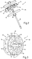
- Figure 2 illustrates a variant of the actuator 7 according to the invention, wherein first coils 13 and second coils 14 are arranged on two opposite sides of a carrier plate 12.
- the carrier plate 12 is also designed as a printed circuit board 29 or board 29.
- the actuator 7 according to Figure 2 has a different number of first coils 13 and second coils 14, ie fewer second coils 14 are present here than first coils 13.
- a first motor 24 has a greater torque and / or a greater output and / or a higher rotational speed than a second motor 24 of the actuator 7.
- the actuator 6 according to FIG Figure 1 advantageously comprises two actuators which can be driven or actuated separately or (essentially) independently by the first motor 13 and on the other hand by the second motor 14.
- the coils 13, 14 or the coil cores of the coils 13, 14, not shown in the interior thereof, are directly mounted / fixed.
- a first motor 24 essentially comprises the carrier plate 12 or the circuit board 29, the first coils 13, a first rotor 15, magnets 23, in particular permanent magnets 23, and preferably a gear / drive wheel 17 or a drive shaft 17
- a second motor 14 essentially comprises the carrier plate 12 or circuit board 29, the second coils 14, a second rotor 16, magnets 23, in particular permanent magnets 23, and preferably a gear / drive wheel 18 or a drive shaft 18.
- the control unit includes, for example, a chip or microprocessor or electrical. Components such as resistors, capacitors or the like.
- the circuit board 29 is equipped or also includes the control unit in the subsequent variants of the invention.
- the sleeve 19 advantageously defines the distance and the position / orientation of the two rotors 15, 16 and, together with the axis 20, forms the sliding / mounting of the rotors 15, 16 (cf. also Figures 3 to 7 ).
- the axis 20 is, for example, firmly fixed / positioned on an actuator housing or the like, so that the axes of rotation of the two rotors 15, 16 or motors 24, 25 are exactly fixed / positioned.
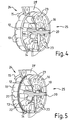
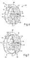
- FIG. 2 to 7 Different variants of the actuators 7 or electric motors 7 according to the invention are shown schematically. In contrast to the variant, however, this is Figure 2 a carrier plate 12 separate from the board 29 is provided. The carrier plate 12 is advantageously firmly connected or screwed to the circuit board 29 (without a more detailed illustration). In addition, various electrical connections or cables or the like are present between the carrier plate 12 and the circuit board 29, for example coil ends of the coils 13, 14 soldered to the circuit board 29.
- first coils 13 and the second coils 14 are in accordance with Figure 3 different (large) dimensions.
- the latter can generally be implemented, for example, with a different number of windings and / or differently thick / thick coil or copper wires or coils 13, 14 with different lengths and / or widths and / or heights.
- the variant according to Figure 4 the same number of first and second coils 13, 14, for example 12 pieces each.
- the second coils 14 are dimensioned significantly smaller than the first coils 13, in particular with regard to the width or windings / wire diameter of the respective coils 13, 14.
- the different (large) dimensioning of the motors 24, 25 or stators can also be achieved according to the invention by different inner and / or outer diameters of the circular ring or coil ring.
- second coil 14 which form a circular ring which has a significantly smaller outer diameter than the outer diameter of the circular ring of the first coils 13 on the other side of the carrier plate 12.
- the number of coils is the same in this example, for example twelve pieces per side.
- the carrier plate 12 or the circuit board 12 or circuit board 12 according to FIG Figure 2 layered or as a structural unit with, for example, two shielding elements 21, 22 or metal layers 21, 22 or so-called short-circuit plates 21, 22.
Landscapes
- Engineering & Computer Science (AREA)
- General Engineering & Computer Science (AREA)
- Mechanical Engineering (AREA)
- Chemical & Material Sciences (AREA)
- Combustion & Propulsion (AREA)
- Power Engineering (AREA)
- Connection Of Motors, Electrical Generators, Mechanical Devices, And The Like (AREA)
- Actuator (AREA)
- Fluid-Driven Valves (AREA)
- Valve Device For Special Equipments (AREA)
Applications Claiming Priority (1)
| Application Number | Priority Date | Filing Date | Title |
|---|---|---|---|
| DE102018132592.4A DE102018132592A1 (de) | 2018-12-18 | 2018-12-18 | Stellantrieb für ein Stellorgan zur Steuerung eines Fluides |
Publications (2)
| Publication Number | Publication Date |
|---|---|
| EP3672039A1 true EP3672039A1 (fr) | 2020-06-24 |
| EP3672039B1 EP3672039B1 (fr) | 2022-04-27 |
Family
ID=67742265
Family Applications (1)
| Application Number | Title | Priority Date | Filing Date |
|---|---|---|---|
| EP19193362.1A Active EP3672039B1 (fr) | 2018-12-18 | 2019-08-23 | Servomoteur pour un organe de réglage permettant de commander un fluide |
Country Status (4)
| Country | Link |
|---|---|
| EP (1) | EP3672039B1 (fr) |
| DE (1) | DE102018132592A1 (fr) |
| ES (1) | ES2918382T3 (fr) |
| HU (1) | HUE059499T2 (fr) |
Citations (5)
| Publication number | Priority date | Publication date | Assignee | Title |
|---|---|---|---|---|
| WO1999039426A1 (fr) * | 1998-01-30 | 1999-08-05 | Schroedl Manfred | Machine electrique |
| JP2009303393A (ja) * | 2008-06-13 | 2009-12-24 | Seiko Epson Corp | ブラシレス電気機械、それを備えた装置、及び、移動体 |
| WO2013056458A1 (fr) * | 2011-10-21 | 2013-04-25 | Dien Ghing-Hsin | Moteur électrique |
| JP5223475B2 (ja) * | 2008-06-09 | 2013-06-26 | 日産自動車株式会社 | 二重反転スクリュー機構 |
| WO2016022369A1 (fr) * | 2014-08-05 | 2016-02-11 | Schaeffler Technologies AG & Co. KG | Module à vanne de gestion thermique avec arbres concentriques pour commande de vanne rotative |
Family Cites Families (3)
| Publication number | Priority date | Publication date | Assignee | Title |
|---|---|---|---|---|
| DE19809123B4 (de) * | 1998-03-04 | 2005-12-01 | Daimlerchrysler Ag | Wasserpumpe für den Kühlkreislauf einer Brennkraftmaschine |
| WO2015155681A1 (fr) * | 2014-04-08 | 2015-10-15 | Aaco Manufacturing S.R.L. | Unité d'entraînement électrique pourvue de sorties d'entraînement qui sont utilisables indépendamment |
| CN106300722A (zh) * | 2015-05-18 | 2017-01-04 | 德昌电机(深圳)有限公司 | 电机与电动泵 |
-
2018
- 2018-12-18 DE DE102018132592.4A patent/DE102018132592A1/de not_active Withdrawn
-
2019
- 2019-08-23 ES ES19193362T patent/ES2918382T3/es active Active
- 2019-08-23 HU HUE19193362A patent/HUE059499T2/hu unknown
- 2019-08-23 EP EP19193362.1A patent/EP3672039B1/fr active Active
Patent Citations (5)
| Publication number | Priority date | Publication date | Assignee | Title |
|---|---|---|---|---|
| WO1999039426A1 (fr) * | 1998-01-30 | 1999-08-05 | Schroedl Manfred | Machine electrique |
| JP5223475B2 (ja) * | 2008-06-09 | 2013-06-26 | 日産自動車株式会社 | 二重反転スクリュー機構 |
| JP2009303393A (ja) * | 2008-06-13 | 2009-12-24 | Seiko Epson Corp | ブラシレス電気機械、それを備えた装置、及び、移動体 |
| WO2013056458A1 (fr) * | 2011-10-21 | 2013-04-25 | Dien Ghing-Hsin | Moteur électrique |
| WO2016022369A1 (fr) * | 2014-08-05 | 2016-02-11 | Schaeffler Technologies AG & Co. KG | Module à vanne de gestion thermique avec arbres concentriques pour commande de vanne rotative |
Also Published As
| Publication number | Publication date |
|---|---|
| ES2918382T3 (es) | 2022-07-15 |
| EP3672039B1 (fr) | 2022-04-27 |
| DE102018132592A1 (de) | 2020-06-18 |
| HUE059499T2 (hu) | 2022-11-28 |
Similar Documents
| Publication | Publication Date | Title |
|---|---|---|
| DE102013222587B4 (de) | Temperaturregelung einer drosselspulenanordnung | |
| EP2305981B1 (fr) | Turbosoufflante électrique | |
| EP1872995B1 (fr) | Dispositif d'entrâinement pour un véhicule à chenilles ou un véhicule à roues avec guidage par les roues latérales | |
| DE10214637A1 (de) | Hybridantrieb und diesen verwendende Hybridpumpe, insbesondere für ein Kraftfahrzeug | |
| DE112012000617T5 (de) | Montageanordnung für eine Leistungssteuereinheit | |
| WO2020207537A1 (fr) | Entraînement électrique comprenant une section d'échangeur de chaleur | |
| DE102013222599A1 (de) | Integrierte Drosselspulenanordnung | |
| DE102019133363A1 (de) | Kühlsystem, elektrische Antriebseinheit, Elektrofahrzeug und Verfahren zum Kühlen einer elektrischen Antriebseinheit | |
| DE102018117987A1 (de) | Elektromotor | |
| DE102023100525A1 (de) | Kühlsystem für eine elektrische Maschine | |
| DE102017215835A1 (de) | Fluidgekühlte elektrische Maschine | |
| DE112020007883T5 (de) | Elektromotor mit Kühlanordnung und Verfahren zur Steuerung einer Kühlanordnung | |
| DE112021005105T5 (de) | Kühlmittelsteuerungsmodul | |
| EP3785351A1 (fr) | Moteur électrique et son procédé de fabrication | |
| DE10011956A1 (de) | Elektrische Maschine sowie Antriebsanordnung für ein Fahrzeug | |
| DE102019120913A1 (de) | Elektromotor | |
| DE212016000048U1 (de) | Pumpengruppe mit gekühlter elektronischer Steuervorrichtung | |
| WO2012146376A2 (fr) | Dispositif d'entraînement pour un véhicule automobile | |
| EP3672039B1 (fr) | Servomoteur pour un organe de réglage permettant de commander un fluide | |
| EP3670858A1 (fr) | Unité de mise en température de moteur destinée au pompage et / ou à la distribution d'un caloporteur | |
| DE102021106888A1 (de) | Kühlsystem, elektrische Antriebseinheit, Elektrofahrzeug und Verfahren zum Kühlen einer elektrischen Antriebseinheit | |
| DE102018205319A1 (de) | Elektrische Heizeinrichtung | |
| DE102022107407B4 (de) | Stator | |
| DE102008054637A1 (de) | Hybridantriebsstrang eines Kraftfahrzeugs | |
| DE10204592A1 (de) | Antriebseinheit |
Legal Events
| Date | Code | Title | Description |
|---|---|---|---|
| PUAI | Public reference made under article 153(3) epc to a published international application that has entered the european phase |
Free format text: ORIGINAL CODE: 0009012 |
|
| STAA | Information on the status of an ep patent application or granted ep patent |
Free format text: STATUS: THE APPLICATION HAS BEEN PUBLISHED |
|
| AK | Designated contracting states |
Kind code of ref document: A1 Designated state(s): AL AT BE BG CH CY CZ DE DK EE ES FI FR GB GR HR HU IE IS IT LI LT LU LV MC MK MT NL NO PL PT RO RS SE SI SK SM TR |
|
| AX | Request for extension of the european patent |
Extension state: BA ME |
|
| STAA | Information on the status of an ep patent application or granted ep patent |
Free format text: STATUS: REQUEST FOR EXAMINATION WAS MADE |
|
| 17P | Request for examination filed |
Effective date: 20201218 |
|
| RBV | Designated contracting states (corrected) |
Designated state(s): AL AT BE BG CH CY CZ DE DK EE ES FI FR GB GR HR HU IE IS IT LI LT LU LV MC MK MT NL NO PL PT RO RS SE SI SK SM TR |
|
| GRAP | Despatch of communication of intention to grant a patent |
Free format text: ORIGINAL CODE: EPIDOSNIGR1 |
|
| STAA | Information on the status of an ep patent application or granted ep patent |
Free format text: STATUS: GRANT OF PATENT IS INTENDED |
|
| RIC1 | Information provided on ipc code assigned before grant |
Ipc: F01P 7/16 20060101ALN20211128BHEP Ipc: F01P 3/20 20060101ALI20211128BHEP Ipc: F16K 31/04 20060101ALI20211128BHEP Ipc: F16K 11/20 20060101ALI20211128BHEP Ipc: F16K 11/18 20060101ALI20211128BHEP Ipc: F16K 11/12 20060101ALI20211128BHEP Ipc: H02K 16/02 20060101AFI20211128BHEP |
|
| INTG | Intention to grant announced |
Effective date: 20211215 |
|
| GRAS | Grant fee paid |
Free format text: ORIGINAL CODE: EPIDOSNIGR3 |
|
| GRAA | (expected) grant |
Free format text: ORIGINAL CODE: 0009210 |
|
| STAA | Information on the status of an ep patent application or granted ep patent |
Free format text: STATUS: THE PATENT HAS BEEN GRANTED |
|
| AK | Designated contracting states |
Kind code of ref document: B1 Designated state(s): AL AT BE BG CH CY CZ DE DK EE ES FI FR GB GR HR HU IE IS IT LI LT LU LV MC MK MT NL NO PL PT RO RS SE SI SK SM TR |
|
| REG | Reference to a national code |
Ref country code: GB Ref legal event code: FG4D Free format text: NOT ENGLISH |
|
| REG | Reference to a national code |
Ref country code: CH Ref legal event code: EP |
|
| REG | Reference to a national code |
Ref country code: AT Ref legal event code: REF Ref document number: 1487741 Country of ref document: AT Kind code of ref document: T Effective date: 20220515 |
|
| REG | Reference to a national code |
Ref country code: DE Ref legal event code: R096 Ref document number: 502019004178 Country of ref document: DE |
|
| REG | Reference to a national code |
Ref country code: IE Ref legal event code: FG4D Free format text: LANGUAGE OF EP DOCUMENT: GERMAN |
|
| REG | Reference to a national code |
Ref country code: ES Ref legal event code: FG2A Ref document number: 2918382 Country of ref document: ES Kind code of ref document: T3 Effective date: 20220715 |
|
| REG | Reference to a national code |
Ref country code: SE Ref legal event code: TRGR |
|
| REG | Reference to a national code |
Ref country code: LT Ref legal event code: MG9D |
|
| REG | Reference to a national code |
Ref country code: NL Ref legal event code: MP Effective date: 20220427 |
|
| PG25 | Lapsed in a contracting state [announced via postgrant information from national office to epo] |
Ref country code: NL Free format text: LAPSE BECAUSE OF FAILURE TO SUBMIT A TRANSLATION OF THE DESCRIPTION OR TO PAY THE FEE WITHIN THE PRESCRIBED TIME-LIMIT Effective date: 20220427 |
|
| PG25 | Lapsed in a contracting state [announced via postgrant information from national office to epo] |
Ref country code: PT Free format text: LAPSE BECAUSE OF FAILURE TO SUBMIT A TRANSLATION OF THE DESCRIPTION OR TO PAY THE FEE WITHIN THE PRESCRIBED TIME-LIMIT Effective date: 20220829 Ref country code: NO Free format text: LAPSE BECAUSE OF FAILURE TO SUBMIT A TRANSLATION OF THE DESCRIPTION OR TO PAY THE FEE WITHIN THE PRESCRIBED TIME-LIMIT Effective date: 20220727 Ref country code: LT Free format text: LAPSE BECAUSE OF FAILURE TO SUBMIT A TRANSLATION OF THE DESCRIPTION OR TO PAY THE FEE WITHIN THE PRESCRIBED TIME-LIMIT Effective date: 20220427 Ref country code: HR Free format text: LAPSE BECAUSE OF FAILURE TO SUBMIT A TRANSLATION OF THE DESCRIPTION OR TO PAY THE FEE WITHIN THE PRESCRIBED TIME-LIMIT Effective date: 20220427 Ref country code: GR Free format text: LAPSE BECAUSE OF FAILURE TO SUBMIT A TRANSLATION OF THE DESCRIPTION OR TO PAY THE FEE WITHIN THE PRESCRIBED TIME-LIMIT Effective date: 20220728 Ref country code: FI Free format text: LAPSE BECAUSE OF FAILURE TO SUBMIT A TRANSLATION OF THE DESCRIPTION OR TO PAY THE FEE WITHIN THE PRESCRIBED TIME-LIMIT Effective date: 20220427 Ref country code: BG Free format text: LAPSE BECAUSE OF FAILURE TO SUBMIT A TRANSLATION OF THE DESCRIPTION OR TO PAY THE FEE WITHIN THE PRESCRIBED TIME-LIMIT Effective date: 20220727 |
|
| REG | Reference to a national code |
Ref country code: HU Ref legal event code: AG4A Ref document number: E059499 Country of ref document: HU |
|
| PG25 | Lapsed in a contracting state [announced via postgrant information from national office to epo] |
Ref country code: RS Free format text: LAPSE BECAUSE OF FAILURE TO SUBMIT A TRANSLATION OF THE DESCRIPTION OR TO PAY THE FEE WITHIN THE PRESCRIBED TIME-LIMIT Effective date: 20220427 Ref country code: PL Free format text: LAPSE BECAUSE OF FAILURE TO SUBMIT A TRANSLATION OF THE DESCRIPTION OR TO PAY THE FEE WITHIN THE PRESCRIBED TIME-LIMIT Effective date: 20220427 Ref country code: LV Free format text: LAPSE BECAUSE OF FAILURE TO SUBMIT A TRANSLATION OF THE DESCRIPTION OR TO PAY THE FEE WITHIN THE PRESCRIBED TIME-LIMIT Effective date: 20220427 Ref country code: IS Free format text: LAPSE BECAUSE OF FAILURE TO SUBMIT A TRANSLATION OF THE DESCRIPTION OR TO PAY THE FEE WITHIN THE PRESCRIBED TIME-LIMIT Effective date: 20220827 |
|
| REG | Reference to a national code |
Ref country code: DE Ref legal event code: R097 Ref document number: 502019004178 Country of ref document: DE |
|
| PG25 | Lapsed in a contracting state [announced via postgrant information from national office to epo] |
Ref country code: SM Free format text: LAPSE BECAUSE OF FAILURE TO SUBMIT A TRANSLATION OF THE DESCRIPTION OR TO PAY THE FEE WITHIN THE PRESCRIBED TIME-LIMIT Effective date: 20220427 Ref country code: SK Free format text: LAPSE BECAUSE OF FAILURE TO SUBMIT A TRANSLATION OF THE DESCRIPTION OR TO PAY THE FEE WITHIN THE PRESCRIBED TIME-LIMIT Effective date: 20220427 Ref country code: RO Free format text: LAPSE BECAUSE OF FAILURE TO SUBMIT A TRANSLATION OF THE DESCRIPTION OR TO PAY THE FEE WITHIN THE PRESCRIBED TIME-LIMIT Effective date: 20220427 Ref country code: EE Free format text: LAPSE BECAUSE OF FAILURE TO SUBMIT A TRANSLATION OF THE DESCRIPTION OR TO PAY THE FEE WITHIN THE PRESCRIBED TIME-LIMIT Effective date: 20220427 Ref country code: DK Free format text: LAPSE BECAUSE OF FAILURE TO SUBMIT A TRANSLATION OF THE DESCRIPTION OR TO PAY THE FEE WITHIN THE PRESCRIBED TIME-LIMIT Effective date: 20220427 |
|
| PLBE | No opposition filed within time limit |
Free format text: ORIGINAL CODE: 0009261 |
|
| STAA | Information on the status of an ep patent application or granted ep patent |
Free format text: STATUS: NO OPPOSITION FILED WITHIN TIME LIMIT |
|
| PG25 | Lapsed in a contracting state [announced via postgrant information from national office to epo] |
Ref country code: MC Free format text: LAPSE BECAUSE OF FAILURE TO SUBMIT A TRANSLATION OF THE DESCRIPTION OR TO PAY THE FEE WITHIN THE PRESCRIBED TIME-LIMIT Effective date: 20220427 Ref country code: AL Free format text: LAPSE BECAUSE OF FAILURE TO SUBMIT A TRANSLATION OF THE DESCRIPTION OR TO PAY THE FEE WITHIN THE PRESCRIBED TIME-LIMIT Effective date: 20220427 |
|
| REG | Reference to a national code |
Ref country code: CH Ref legal event code: PL |
|
| 26N | No opposition filed |
Effective date: 20230130 |
|
| PG25 | Lapsed in a contracting state [announced via postgrant information from national office to epo] |
Ref country code: LU Free format text: LAPSE BECAUSE OF NON-PAYMENT OF DUE FEES Effective date: 20220823 Ref country code: LI Free format text: LAPSE BECAUSE OF NON-PAYMENT OF DUE FEES Effective date: 20220831 Ref country code: CH Free format text: LAPSE BECAUSE OF NON-PAYMENT OF DUE FEES Effective date: 20220831 |
|
| REG | Reference to a national code |
Ref country code: BE Ref legal event code: MM Effective date: 20220831 |
|
| PG25 | Lapsed in a contracting state [announced via postgrant information from national office to epo] |
Ref country code: SI Free format text: LAPSE BECAUSE OF FAILURE TO SUBMIT A TRANSLATION OF THE DESCRIPTION OR TO PAY THE FEE WITHIN THE PRESCRIBED TIME-LIMIT Effective date: 20220427 |
|
| PG25 | Lapsed in a contracting state [announced via postgrant information from national office to epo] |
Ref country code: IE Free format text: LAPSE BECAUSE OF NON-PAYMENT OF DUE FEES Effective date: 20220823 |
|
| PG25 | Lapsed in a contracting state [announced via postgrant information from national office to epo] |
Ref country code: BE Free format text: LAPSE BECAUSE OF NON-PAYMENT OF DUE FEES Effective date: 20220831 |
|
| PG25 | Lapsed in a contracting state [announced via postgrant information from national office to epo] |
Ref country code: CY Free format text: LAPSE BECAUSE OF FAILURE TO SUBMIT A TRANSLATION OF THE DESCRIPTION OR TO PAY THE FEE WITHIN THE PRESCRIBED TIME-LIMIT Effective date: 20220427 |
|
| PG25 | Lapsed in a contracting state [announced via postgrant information from national office to epo] |
Ref country code: MK Free format text: LAPSE BECAUSE OF FAILURE TO SUBMIT A TRANSLATION OF THE DESCRIPTION OR TO PAY THE FEE WITHIN THE PRESCRIBED TIME-LIMIT Effective date: 20220427 |
|
| PG25 | Lapsed in a contracting state [announced via postgrant information from national office to epo] |
Ref country code: TR Free format text: LAPSE BECAUSE OF FAILURE TO SUBMIT A TRANSLATION OF THE DESCRIPTION OR TO PAY THE FEE WITHIN THE PRESCRIBED TIME-LIMIT Effective date: 20220427 |
|
| PG25 | Lapsed in a contracting state [announced via postgrant information from national office to epo] |
Ref country code: MT Free format text: LAPSE BECAUSE OF FAILURE TO SUBMIT A TRANSLATION OF THE DESCRIPTION OR TO PAY THE FEE WITHIN THE PRESCRIBED TIME-LIMIT Effective date: 20220427 |
|
| PG25 | Lapsed in a contracting state [announced via postgrant information from national office to epo] |
Ref country code: BG Free format text: LAPSE BECAUSE OF FAILURE TO SUBMIT A TRANSLATION OF THE DESCRIPTION OR TO PAY THE FEE WITHIN THE PRESCRIBED TIME-LIMIT Effective date: 20220427 |
|
| PG25 | Lapsed in a contracting state [announced via postgrant information from national office to epo] |
Ref country code: BG Free format text: LAPSE BECAUSE OF FAILURE TO SUBMIT A TRANSLATION OF THE DESCRIPTION OR TO PAY THE FEE WITHIN THE PRESCRIBED TIME-LIMIT Effective date: 20220427 |
|
| REG | Reference to a national code |
Ref country code: DE Ref legal event code: R082 Ref document number: 502019004178 Country of ref document: DE Representative=s name: RAVENSPAT PATENTANWAELTE PARTNERSCHAFT MBB, DE |
|
| PGFP | Annual fee paid to national office [announced via postgrant information from national office to epo] |
Ref country code: HU Payment date: 20250814 Year of fee payment: 7 |
|
| PGFP | Annual fee paid to national office [announced via postgrant information from national office to epo] |
Ref country code: ES Payment date: 20250917 Year of fee payment: 7 |
|
| PGFP | Annual fee paid to national office [announced via postgrant information from national office to epo] |
Ref country code: DE Payment date: 20250819 Year of fee payment: 7 |
|
| PGFP | Annual fee paid to national office [announced via postgrant information from national office to epo] |
Ref country code: IT Payment date: 20250829 Year of fee payment: 7 |
|
| REG | Reference to a national code |
Ref country code: AT Ref legal event code: MM01 Ref document number: 1487741 Country of ref document: AT Kind code of ref document: T Effective date: 20240823 |
|
| PGFP | Annual fee paid to national office [announced via postgrant information from national office to epo] |
Ref country code: GB Payment date: 20250822 Year of fee payment: 7 |
|
| PG25 | Lapsed in a contracting state [announced via postgrant information from national office to epo] |
Ref country code: AT Free format text: LAPSE BECAUSE OF NON-PAYMENT OF DUE FEES Effective date: 20240823 |
|
| PGFP | Annual fee paid to national office [announced via postgrant information from national office to epo] |
Ref country code: FR Payment date: 20250821 Year of fee payment: 7 |
|
| PGFP | Annual fee paid to national office [announced via postgrant information from national office to epo] |
Ref country code: SE Payment date: 20250821 Year of fee payment: 7 |
|
| PGFP | Annual fee paid to national office [announced via postgrant information from national office to epo] |
Ref country code: CZ Payment date: 20250808 Year of fee payment: 7 |
|
| PGFP | Annual fee paid to national office [announced via postgrant information from national office to epo] |
Ref country code: AT Payment date: 20260410 Year of fee payment: 5 |