EP3672101A1 - Phare de véhicule apte à la communication - Google Patents
Phare de véhicule apte à la communication Download PDFInfo
- Publication number
- EP3672101A1 EP3672101A1 EP18215054.0A EP18215054A EP3672101A1 EP 3672101 A1 EP3672101 A1 EP 3672101A1 EP 18215054 A EP18215054 A EP 18215054A EP 3672101 A1 EP3672101 A1 EP 3672101A1
- Authority
- EP
- European Patent Office
- Prior art keywords
- vehicle
- light
- unit
- radiation
- data
- Prior art date
- Legal status (The legal status is an assumption and is not a legal conclusion. Google has not performed a legal analysis and makes no representation as to the accuracy of the status listed.)
- Withdrawn
Links
- 238000009826 distribution Methods 0.000 claims abstract description 61
- 230000005855 radiation Effects 0.000 claims abstract description 38
- 230000001419 dependent effect Effects 0.000 claims abstract description 37
- 230000000694 effects Effects 0.000 claims abstract description 4
- 230000005540 biological transmission Effects 0.000 claims description 41
- 238000004891 communication Methods 0.000 claims description 15
- 230000003287 optical effect Effects 0.000 claims description 6
- 238000011156 evaluation Methods 0.000 claims description 4
- 230000007613 environmental effect Effects 0.000 claims description 3
- 230000033228 biological regulation Effects 0.000 description 4
- 239000011248 coating agent Substances 0.000 description 4
- 238000000576 coating method Methods 0.000 description 4
- RYGMFSIKBFXOCR-UHFFFAOYSA-N Copper Chemical compound [Cu] RYGMFSIKBFXOCR-UHFFFAOYSA-N 0.000 description 2
- 230000003044 adaptive effect Effects 0.000 description 2
- 229910052782 aluminium Inorganic materials 0.000 description 2
- XAGFODPZIPBFFR-UHFFFAOYSA-N aluminium Chemical compound [Al] XAGFODPZIPBFFR-UHFFFAOYSA-N 0.000 description 2
- 229910052802 copper Inorganic materials 0.000 description 2
- 239000010949 copper Substances 0.000 description 2
- 230000002349 favourable effect Effects 0.000 description 2
- 239000011521 glass Substances 0.000 description 2
- 238000001228 spectrum Methods 0.000 description 2
- 241000283070 Equus zebra Species 0.000 description 1
- 230000003190 augmentative effect Effects 0.000 description 1
- 230000007423 decrease Effects 0.000 description 1
- 230000005670 electromagnetic radiation Effects 0.000 description 1
- 238000005516 engineering process Methods 0.000 description 1
- 238000009434 installation Methods 0.000 description 1
- 239000000463 material Substances 0.000 description 1
- 229910052751 metal Inorganic materials 0.000 description 1
- 239000002184 metal Substances 0.000 description 1
- 230000000422 nocturnal effect Effects 0.000 description 1
- ZRHANBBTXQZFSP-UHFFFAOYSA-M potassium;4-amino-3,5,6-trichloropyridine-2-carboxylate Chemical compound [K+].NC1=C(Cl)C(Cl)=NC(C([O-])=O)=C1Cl ZRHANBBTXQZFSP-UHFFFAOYSA-M 0.000 description 1
- 230000011664 signaling Effects 0.000 description 1
- 239000004984 smart glass Substances 0.000 description 1
- 230000001360 synchronised effect Effects 0.000 description 1
- 230000001960 triggered effect Effects 0.000 description 1
Images
Classifications
-
- H—ELECTRICITY
- H04—ELECTRIC COMMUNICATION TECHNIQUE
- H04B—TRANSMISSION
- H04B7/00—Radio transmission systems, i.e. using radiation field
- H04B7/02—Diversity systems; Multi-antenna system, i.e. transmission or reception using multiple antennas
- H04B7/04—Diversity systems; Multi-antenna system, i.e. transmission or reception using multiple antennas using two or more spaced independent antennas
- H04B7/06—Diversity systems; Multi-antenna system, i.e. transmission or reception using multiple antennas using two or more spaced independent antennas at the transmitting station
- H04B7/0613—Diversity systems; Multi-antenna system, i.e. transmission or reception using multiple antennas using two or more spaced independent antennas at the transmitting station using simultaneous transmission
- H04B7/0615—Diversity systems; Multi-antenna system, i.e. transmission or reception using multiple antennas using two or more spaced independent antennas at the transmitting station using simultaneous transmission of weighted versions of same signal
- H04B7/0617—Diversity systems; Multi-antenna system, i.e. transmission or reception using multiple antennas using two or more spaced independent antennas at the transmitting station using simultaneous transmission of weighted versions of same signal for beam forming
-
- B—PERFORMING OPERATIONS; TRANSPORTING
- B60—VEHICLES IN GENERAL
- B60Q—ARRANGEMENT OF SIGNALLING OR LIGHTING DEVICES, THE MOUNTING OR SUPPORTING THEREOF OR CIRCUITS THEREFOR, FOR VEHICLES IN GENERAL
- B60Q1/00—Arrangement of optical signalling or lighting devices, the mounting or supporting thereof or circuits therefor
- B60Q1/0017—Devices integrating an element dedicated to another function
-
- B—PERFORMING OPERATIONS; TRANSPORTING
- B60—VEHICLES IN GENERAL
- B60Q—ARRANGEMENT OF SIGNALLING OR LIGHTING DEVICES, THE MOUNTING OR SUPPORTING THEREOF OR CIRCUITS THEREFOR, FOR VEHICLES IN GENERAL
- B60Q1/00—Arrangement of optical signalling or lighting devices, the mounting or supporting thereof or circuits therefor
- B60Q1/26—Arrangement of optical signalling or lighting devices, the mounting or supporting thereof or circuits therefor the devices being primarily intended to indicate the vehicle, or parts thereof, or to give signals, to other traffic
- B60Q1/50—Arrangement of optical signalling or lighting devices, the mounting or supporting thereof or circuits therefor the devices being primarily intended to indicate the vehicle, or parts thereof, or to give signals, to other traffic for indicating other intentions or conditions, e.g. request for waiting or overtaking
- B60Q1/525—Arrangement of optical signalling or lighting devices, the mounting or supporting thereof or circuits therefor the devices being primarily intended to indicate the vehicle, or parts thereof, or to give signals, to other traffic for indicating other intentions or conditions, e.g. request for waiting or overtaking automatically indicating risk of collision between vehicles in traffic or with pedestrians, e.g. after risk assessment using the vehicle sensor data
Definitions
- Vehicle headlights capable of communication have become known from the prior art.
- a headlamp is known in which the light emission of the headlamp can be manipulated in order to provide third parties with targeted information based on the manipulation of the light emission.
- the light module of the headlamp thus also acts as a transmitter unit, which means that the possibilities for information transmission are significantly restricted.
- a light module for a headlight has become known that comprises an antenna, by means of which information can be emitted to the surroundings of the light module.
- the radiation of anti-collision radar signals is mentioned in particular.
- this device has the disadvantage that the information radiation is largely undirected and thus reaches road users for whom the transmitted information is irrelevant. In the best case, the transmitted information is ignored by the (not!) Concerned road user, in the worst case the information is misinterpreted and measures such as for example, an emergency stop is initiated. In any case, the undirected radiation means that information can also reach those road users for whom this information is irrelevant. This leads to increased data volume, the risk of misinterpretation as well as the risk that traffic-related information of a fourth person may not be recorded in time or not sufficiently.
- This object is achieved with a headlamp of the type mentioned at the outset, in which, according to the invention, the transmitting unit is arranged in such a way and is set up to emit the driving-dependent data in a directed manner, the directional effect being such that the emission of the driving-dependent data is essentially based on the light distribution of the at least one light module detectable space is limited, wherein the radiation from the transmitter unit is free of visible light.
- the transmitting unit is therefore not a light module, but rather, for example, a transmitter comprising an antenna that is set up to transmit digital data.
- Biquad antennas, waveguide antennas (ie horn radiators) can be used for this purpose.
- the use of horn emitters can be favorable, since their geometric shape resembles conventional light reflector shapes.
- the transmission signals can be emitted and possibly also received.
- the frequency range of the transmission signal can range, for example, between 300 MHz and 3 GHz.
- the range can also range from 20 MHz to 3 GHz. This means that both WLAN frequencies (20 MHz to 160 MHz) and Bluetooth frequencies (approx.
- the headlamp according to the invention ensures that the information is only radiated into the area that the vehicle can theoretically drive on when driving straight ahead or cornering. The information is thus only sent to those road users for whom the information is also relevant. The headlight thus enables increased road safety for all road users involved.
- communication is already understood here to mean the one-sided (unidirectional) transmission of information, i.e. no response from the information recipients is required.
- space detectable by the light distribution of the at least one light module is understood to mean a space that is illuminated due to the radiation of the light distribution.
- the emission of the travel-dependent data is essentially limited to the space that can be detected by the light distribution of the at least one light module
- the aim is to access the drive-dependent data as well as possible only in the space that can be detected by the light module do. This is to be understood within the limits of the directivity of radiation by antennas and transmitters. It goes without saying that an absolutely sharp limit is not possible due to the continuity of the radiated quantities, for example electromagnetic waves.
- the expression is therefore to be understood to mean that the intensity of the emitted information within the detectable space lies within a maximum range and decreases rapidly and continuously outside this space.
- a projection of the light image onto a vertical surface is generated in accordance with the relevant standards, for example in accordance with regulations number 123 and 48 of the United Nations Economic Commission for Europe (UN / ECE) "Uniform conditions for the approval of adaptive front lighting systems (AFS) for motor vehicles "and” Uniform conditions for the approval of the vehicles with regard to the installation of the lighting and light signaling devices ", the Federal Motor Vehicle Safety Standard FMVSS No. valid for the United States of America.
- AFS adaptive front lighting systems
- a low beam distribution as well as other light distributions are sufficiently defined in the relevant standards.
- the vehicle headlight also has a computing unit for controlling the transmission unit.
- the vehicle headlight comprises at least one optical sensor, in particular a camera, for at least partially detecting the space that can be detected by the light distribution of the at least one light module, the data detected by the optical sensor being fed to the computing unit, the computing unit being used for this purpose is set up, based on this, to detect other road users, in particular vehicles and / or pedestrians, the transmission unit being set up to segment the radiation into said detectable space and thereby the intensity of the radiation and / or the content of the emitted information between different ones Varying segments, and segments in which road users are recorded, based on this, with respect to intensity and / or the emitted information, in a manner which differs from the remaining segments.
- the vehicle headlight comprises at least one optical sensor, in particular a camera, for at least partially detecting the space that can be detected by the light distribution of the at least one light module, the data detected by the optical sensor being fed to the computing unit, the computing unit being used for this purpose is set up, based on this, to detect other road users, in particular vehicles and
- the deviation can take place, for example, in a way that allows a targeted transmission of differently adapted information.
- warning signals, stop signals, priority signals, subordinate signals, "free travel" signals or other signals can be specifically transmitted to the individual road users. These signals can, for example, be transmitted to pedestrians' smartphones or wearables (such as smart glasses). It is also conceivable to transfer this data to other vehicles. Such communication can be of great advantage especially in autonomous vehicles, which can automatically react to the information sent.
- the at least one light module and / or a further light module is further configured to emit a high beam distribution, the transmitter unit being set up to expand the radiation in accordance with an expanded space detected by the high beam distribution.
- the transmitter unit being set up to expand the radiation in accordance with an expanded space detected by the high beam distribution.
- several light modules can be provided, or individual light modules can perform several light functions. Examples of different light distributions include the document AT 514967 B1 removable.
- the vehicle headlight comprises a receiving unit for receiving environmental data, in particular data relating to the position and direction of movement of other road users.
- the light module can have a light source and a reflector, the reflector being set up to emit the light emitted by the light source in the form of a predetermined light distribution, the reflector also providing the travel-dependent data in the form of a time sequence Correspondingly coded electromagnetic waves are supplied, the reflector being set up to emit the electromagnetic waves of the transmitter unit using its directivity to generate the light distribution.
- the shape of the radiation directed by the transmission unit is designed such that it covers only the space covered by the light distribution.
- biquad antennas, waveguide antennas ie horn radiators
- the use of horn emitters can be favorable, since their geometric shape resembles conventional light reflector shapes.
- the transmission signals can be emitted and possibly also received.
- the frequency range of the transmission signal can range, for example, between 300 MHz and 3 GHz.
- the range can also range from 20 MHz to 3 GHz. So that both WiFi frequencies (20 MHz to 160 MHz) and Bluetooth frequencies (approx. 2.4 GHz) can be included in the frequency spectrum.
- the cover plate is made of plastic.
- the possibility of emitting information to the outside through the cover plate of the vehicle headlight is particularly advantageous since other areas of vehicles are regularly covered by metal parts which make it difficult to emit radiation.
- the invention relates to a vehicle, in particular a motor vehicle, comprising a vehicle headlight according to the invention.
- the recipients of the data can compare their direction of movement with the direction of movement of the vehicle and check the presence of a risk of collision.
- the vehicle also comprises a navigation system, the navigation system being connected to the vehicle computing unit, and navigation data being supplied to the vehicle computing unit, the vehicle computing unit being set up to derive travel direction information therefrom and to include this in the travel-dependent data to be transmitted as additional information and to be emitted by the transmitter unit.
- the recipients of the data can compare their direction of movement with the current and a direction of movement of the vehicle, which is predicted based on the navigation data, and check for the presence of a collision risk.
- the vehicle computing unit is set up to provide travel and position information of the vehicle in order to distinguish the nocturnal ones Admissibility of low beam or high beam distribution to be used, and to specify the radiation by the transmission unit as a function of it, the radiation being carried out by the transmission unit regardless of whether the low beam or high beam distribution is actually emitted. It is therefore irrelevant whether the light modules actually emit light.
- the light modules can be out of operation in bright daylight, for example, and yet the light distribution of the light modules that is present during operation can be used as a reference for the radiation.
- the high beam is activated when driving at a higher speed out of place.
- the spatial area covered by the high beam distribution is enlarged compared to the low beam distribution.
- the radiation is also expanded analogously. This is particularly advantageous since speeds are increased especially in situations in which a high beam distribution can be used, and a longer range of the radiation is therefore desirable.
- the invention further relates to a traffic safety system comprising a vehicle according to the invention and at least one further object that identifies a road user, in particular a vehicle, a smartphone, or another portable processor-controlled device, the at least one further object being a reception and evaluation unit for receiving and for Evaluation of the drive-dependent data emitted by the transmission unit of the vehicle has.
- the background of the invention and the invention itself can also be described as follows:
- the topic of "autonomous driving” is on the rise.
- Some systems that enable partially automated driving are already available here, such as cruise control, lane departure warning, parking assistant.
- the vehicle needs different communication interfaces to the outside world.
- information can be transferred into the vehicle from the outside via these interfaces (e.g. camera images of the surroundings, GPS information, ...) on the other hand, the vehicle can also communicate with the environment.
- a frequently cited example here is communication with other road users, such as pedestrians.
- An object of this invention is to establish communication with road users who are in the immediate “danger area of the vehicle”.
- This invention describes a communication system that rotates around the headlight of the vehicle.
- the aim is to drastically improve the uniqueness of the assignment of signals to the respective other road users.
- the invention is based on the utilization of the "field of view of the headlamp", which can be represented, for example, by a beamed low beam distribution.
- the headlight has the task of illuminating the road area in front of the vehicle.
- the illuminated area is the area in which the vehicle will usually drive.
- This fact is used by the invention to provide only road users who are in this area with information.
- Headlights and especially the lenses, are typically made of plastic and are therefore transparent to a wide frequency range of electromagnetic radiation. This means that the transmitter itself can be protected in the headlight housing and still establish communication with the outside world.
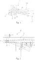
- FIG. 1 shows a schematic representation of a communication-capable vehicle headlight 1 according to the invention.
- This vehicle headlight 1 comprises at least one light module 2 for emitting light onto a roadway 3 (see Fig. 2 ) at least in the form of a low-beam light distribution A-LV, and at least one transmission unit 4 for spatially gapless radiation of driving-dependent data D in the space 5 that can be detected by the light distribution A-LV of the at least one light module 2.
- This space 5 in turn detects a potential movement space of the Vehicle headlamp 1 comprising vehicle 6.
- the expression “potential movement space” is not dependent on the type of vehicle 6, but in the sense of the present invention is only determined by the position and orientation of vehicle headlight 1, vehicle headlight 1 being arranged on the front of vehicle 6 and thus in the direction of travel is oriented.
- the vehicle headlight 1 further comprises at least one vehicle headlight housing 7 which is closed by a cover plate 8.
- the light module 2 and the transmitter unit 4 are arranged within the vehicle headlight housing 7.
- the cover disk 8 is designed in such a way that it is transparent to the light from the light module 2 and the radiation from the transmission unit 4.
- the transmitter unit 4 is arranged and set up in such a way that the drive-dependent data D are emitted in a directed manner.
- the directional effect is designed such that the emission of the drive-dependent data D is essentially limited to the space 5 that can be detected by the light distribution A-LV of the at least one light module 2.
- the emission of the transmitter unit 4 is free of visible light.
- the travel-dependent data D can include information relating to the direction of travel and the speed of travel of a vehicle 6 comprising the vehicle headlight 1.
- the transmission unit 4 is designed to emit this data D into the space 5 that can be detected by the light distribution of the at least one lighting module 2.
- the transmission unit 4 has an interface via which the journey-dependent data D are supplied to the transmission unit 4.
- the vehicle headlight 1 can have a computing unit 9 for controlling the transmission unit 4.
- the vehicle headlight 1 comprises at least one optical sensor 10, in particular a camera, for at least partially detecting the space 5 that can be detected by the light distribution of the at least one light module 2.
- the data captured by the optical sensor 10 are fed to the computing unit 9, the computing unit 9 being set up to capture other road users 11, in particular vehicles and / or pedestrians, on the basis thereof.
- the transmission unit 4 can be designed such that the radiation is segmented into said detectable space 5 and the intensity of the radiation and / or the content of the emitted information D is varied between different segments. In this way, segments in which road users 11 are detected can be specially treated with regard to intensity and / or the emitted information D.
- the signal intensity in this segment can be increased in order to increase the reliability of the signal recognition by the road user 11.
- the information D itself can also be adapted, for example by adding additional warning notices if a risk of collision is determined.
- stop signals can be transmitted.
- the at least one light module 2 and / or a further light module is also set up to emit a high-beam light distribution F-LV, the transmission unit 4 being set up to emit the radiation in accordance with an expanded space detected by the high-beam light distribution F-LV 5 to expand.
- the vehicle headlight 1 comprises a receiving unit 12 for receiving environmental data, in particular data relating to the position and direction of movement of other road users 11.
- the vehicle headlight 1 can also communicate with other communication-capable devices, in particular communication-capable vehicle headlights of oncoming vehicles or smartphones or augmented reality glasses or other wearables of road users and in this way also acquire information about road users 11.
- the travel of the vehicle 6 comprising the vehicle headlight 1 itself can be adapted, for example by slowing down the travel speed and thus avoiding a collision.
- the light module 2 has a light source 2a and a reflector 2b, the reflector 2b being set up to emit the light emitted by the light source 2a in the form of a predetermined light distribution.
- the light distribution can be the low-beam light distribution A-LV already mentioned.
- the reflector 2b is additionally supplied with the signals representing the travel-dependent data D from the transmitter unit 4 in the form of a chronological sequence of correspondingly coded electromagnetic waves, the reflector 2b for emitting the electromagnetic waves from the transmitter unit 4 using its directivity, which was originally used for Generation of the light distribution A-LV, F-LV is provided.
- the light distribution that is emitted by the reflector is represented by exemplary light beams L1, L2 and L3.
- the data radiation is represented by exemplary "data beams" D, which are represented by dashed arrow symbols.
- FIG. 2 shows a schematic representation of a security system 15 according to the invention and a vehicle 6 according to the invention comprising a vehicle headlight 1 according to the invention. More specifically, this is a case example in which a vehicle 6 enters an intersection area.
- Road user 11 in the present case a pedestrian, is located in the potential range of movement of the vehicle 6, that is to say a potential danger area, and should accordingly also be supplied with information.
- Road user 11a in the present case another pedestrian, on the other hand, is on the other side of the road outside the potential range of movement of vehicle 6 and should not be involved in the information exchange.
- the communication from the vehicle 6 to the pedestrian 11 takes place via at least one of the two headlights 1.
- the radiation area of the vehicle headlights 1 overlap and both of them Vehicle headlights 1 emitted the same information.
- the vehicle headlights 1 can be connected to one another and, for example, synchronized.
- Pedestrian 11 could, for example, carry a smartphone with them, which is set up to communicate with the vehicle headlight 1.
- the transmitter unit 4 integrated in the headlight 1 sends directional data streams to the pedestrian 11.
- the information can e.g. read as follows: "The vehicle 6 next to you, red station wagon, is driving on straight ahead. Crossing road 16 can be passed.” This information can be shown on the display of the pedestrian 11.
- the pedestrian 11a on the other hand, does not receive any information since he is not in the field of vision of the vehicle headlight or in the potential range of movement of the vehicle 6. He therefore remains unaffected by the communication.
- the headlight 1 Furthermore, it is possible to send information that is present on the terminal at the pedestrian 11 to the headlight 1, which can receive it.
- the communication can be triggered, for example, by “making contact” with the headlight 1, whereupon the end device of the pedestrian 11 transmits data to the headlight 1.
- Pedestrian 11b is thus also in the field of view of headlights 1 and also receives information D.
- the pedestrian 11b moves in a direction that indicates that a main road 17 has been crossed.
- This information can be reported back to the vehicle 6, as a result of which the vehicle 6 is put into a particularly vigilant mode and thereby closely monitors the pedestrian 11b. For example, if there is a zebra crossing on main road 17 in this area, vehicle 6 could reduce its speed in order to let pedestrian 11b pass.
- vehicle 6 could also first send a stop signal to pedestrian 11b.
- Another pedestrian 11c is also captured by the information exchange, since it is located within the space captured by the low beam distribution. This pedestrian 11c, however, moves away from the main street 17, parallel to the transverse street 16 alongside it. The journey-dependent data D are therefore not relevant to him.
- the App on the terminal of the pedestrian 3 can, from a combination of the information from the vehicle 6 plus the movement information of the terminal itself ("I'm going straight, away from the main road 15), classify the information received from the vehicle as not relevant and therefore not on the display of the pedestrian 11c Show.
- the vehicle 6 has at least one means 13 for determining the speed and the position of the vehicle 6, the position determining means in particular comprising at least one camera and / or a GPS sensor.
- the vehicle 6 also has a vehicle computing unit 14, which is connected to the said means 13 and the transmission unit 4 and is set up to calculate the travel-dependent data D, taking into account the data supplied by these means 13, and the transmission unit 4 for transmitting the travel-dependent data Control data 4 in the space 5 that can be detected by the light distribution of the at least one lighting module 2.
- the vehicle can include a navigation system, the navigation system being connected to the vehicle computing unit 14, and navigation data being supplied to the vehicle computing unit 14, the vehicle computing unit 14 being set up to derive travel direction information therefrom and to include it in the journey-dependent data D to be transmitted as additional information and by to let the transmitter unit 4 emit.
- the vehicle computing unit 14 is set up to use travel and position information of the vehicle 6 to differentiate the nighttime admissibility of the low beam distribution A-LV or the high beam distribution F-LV, and to specify the radiation by the transmission unit 4 as a function thereof, the radiation by the transmission unit 4 regardless of whether the low beam distribution A-LV or the high beam distribution F-LV is actually emitted.
- the invention also relates to a traffic safety system 15, comprising a vehicle 6 according to the invention and at least one further object, in particular a vehicle, a smartphone, or another portable processor-controlled device, which characterizes a road user 11, the at least one further object being a receiving and evaluation unit for Receiving and for evaluating the drive-dependent data D emitted by the transmission unit 4 of the vehicle 6.
Landscapes
- Engineering & Computer Science (AREA)
- Mechanical Engineering (AREA)
- Computer Networks & Wireless Communication (AREA)
- Signal Processing (AREA)
- Lighting Device Outwards From Vehicle And Optical Signal (AREA)
Priority Applications (1)
| Application Number | Priority Date | Filing Date | Title |
|---|---|---|---|
| EP18215054.0A EP3672101A1 (fr) | 2018-12-21 | 2018-12-21 | Phare de véhicule apte à la communication |
Applications Claiming Priority (1)
| Application Number | Priority Date | Filing Date | Title |
|---|---|---|---|
| EP18215054.0A EP3672101A1 (fr) | 2018-12-21 | 2018-12-21 | Phare de véhicule apte à la communication |
Publications (1)
| Publication Number | Publication Date |
|---|---|
| EP3672101A1 true EP3672101A1 (fr) | 2020-06-24 |
Family
ID=64755367
Family Applications (1)
| Application Number | Title | Priority Date | Filing Date |
|---|---|---|---|
| EP18215054.0A Withdrawn EP3672101A1 (fr) | 2018-12-21 | 2018-12-21 | Phare de véhicule apte à la communication |
Country Status (1)
| Country | Link |
|---|---|
| EP (1) | EP3672101A1 (fr) |
Citations (11)
| Publication number | Priority date | Publication date | Assignee | Title |
|---|---|---|---|---|
| EP0559546A1 (fr) | 1992-03-03 | 1993-09-08 | Thomson-Trt Defense | Antenne hyperfréquence à faible coût pour système émetteur et/ou récepteur de véhicule et ampoule de phare pour sa réalisation |
| EP1657787A1 (fr) * | 2004-11-12 | 2006-05-17 | Delphi Technologies, Inc. | Antenne directionnelle |
| EP1739787A1 (fr) * | 2005-06-22 | 2007-01-03 | Delphi Technologies, Inc. | Antenne directionnelle utilisant un réflecteur de lumière |
| US7527440B1 (en) * | 2006-06-05 | 2009-05-05 | White Osborn L | Triangular vehicle light apparatus with camera |
| US20110313609A1 (en) * | 2009-03-06 | 2011-12-22 | Toyota Jidosha Kabushiki Kaisha | Vehicle drive support device |
| AT514967B1 (de) | 2013-10-25 | 2015-08-15 | Zizala Lichtsysteme Gmbh | Mikroprojektions-Lichtmodul für einen Kraftfahrzeugscheinwerfer |
| US20170018187A1 (en) * | 2015-07-14 | 2017-01-19 | Samsung Electronics Co., Ltd | Apparatus and method for providing service in vehicle to everything communication system |
| US9566901B1 (en) * | 2016-05-03 | 2017-02-14 | Toyota Motor Engineering & Manufacturing North America, Inc. | Vehicle indicating side marker lighting systems |
| US20170144585A1 (en) * | 2015-11-25 | 2017-05-25 | Fuji Jukogyo Kabushiki Kaisha | Vehicle exterior environment recognition apparatus |
| EP3260347A1 (fr) * | 2015-02-16 | 2017-12-27 | Yuyang DNU Co., Ltd | Dispositif de sécurité de véhicule utilisant une communication de lumière visible |
| CN105657045B (zh) * | 2016-02-23 | 2018-10-23 | 重庆长安汽车股份有限公司 | 汽车智能大灯的车辆探测与分级方法及系统 |
-
2018
- 2018-12-21 EP EP18215054.0A patent/EP3672101A1/fr not_active Withdrawn
Patent Citations (11)
| Publication number | Priority date | Publication date | Assignee | Title |
|---|---|---|---|---|
| EP0559546A1 (fr) | 1992-03-03 | 1993-09-08 | Thomson-Trt Defense | Antenne hyperfréquence à faible coût pour système émetteur et/ou récepteur de véhicule et ampoule de phare pour sa réalisation |
| EP1657787A1 (fr) * | 2004-11-12 | 2006-05-17 | Delphi Technologies, Inc. | Antenne directionnelle |
| EP1739787A1 (fr) * | 2005-06-22 | 2007-01-03 | Delphi Technologies, Inc. | Antenne directionnelle utilisant un réflecteur de lumière |
| US7527440B1 (en) * | 2006-06-05 | 2009-05-05 | White Osborn L | Triangular vehicle light apparatus with camera |
| US20110313609A1 (en) * | 2009-03-06 | 2011-12-22 | Toyota Jidosha Kabushiki Kaisha | Vehicle drive support device |
| AT514967B1 (de) | 2013-10-25 | 2015-08-15 | Zizala Lichtsysteme Gmbh | Mikroprojektions-Lichtmodul für einen Kraftfahrzeugscheinwerfer |
| EP3260347A1 (fr) * | 2015-02-16 | 2017-12-27 | Yuyang DNU Co., Ltd | Dispositif de sécurité de véhicule utilisant une communication de lumière visible |
| US20170018187A1 (en) * | 2015-07-14 | 2017-01-19 | Samsung Electronics Co., Ltd | Apparatus and method for providing service in vehicle to everything communication system |
| US20170144585A1 (en) * | 2015-11-25 | 2017-05-25 | Fuji Jukogyo Kabushiki Kaisha | Vehicle exterior environment recognition apparatus |
| CN105657045B (zh) * | 2016-02-23 | 2018-10-23 | 重庆长安汽车股份有限公司 | 汽车智能大灯的车辆探测与分级方法及系统 |
| US9566901B1 (en) * | 2016-05-03 | 2017-02-14 | Toyota Motor Engineering & Manufacturing North America, Inc. | Vehicle indicating side marker lighting systems |
Similar Documents
| Publication | Publication Date | Title |
|---|---|---|
| EP0959442B1 (fr) | Procédé de transmission d'information sur les données relatives à un véhicule et système d'information sur le trafic | |
| DE102011081394B3 (de) | Verfahren und Steuergerät zum Hervorheben eines erwarteten Bewegungspfads eines Fahrzeugs | |
| EP2620929B1 (fr) | Procédé et dispositif de reconnaissance d'une situation particulière dans le trafic routier | |
| DE19948733B4 (de) | Fahrzeugkommunikationssystem | |
| DE102016002230B4 (de) | Verfahren zum Betrieb eines Kraftfahrzeugs und Kraftfahrzeug | |
| DE112017006529T5 (de) | Einstrahlungs-steuervorrichtung und einstrahlungs-verfahren | |
| DE102018129849A1 (de) | Scheinwerfersteuerung basierend auf Nachrichten- und Sensordaten | |
| DE102011076644B4 (de) | Verfahren zum Steuern einer variablen Lichtverteilung eines Scheinwerfers eines Kraftfahrzeugs | |
| DE102012224465A1 (de) | Scheinwerfer-steuersystem und -verfahren für ein fahrzeug | |
| WO2009074671A1 (fr) | Procédé et système d'ajustement d'un véhicule | |
| DE102014213131A1 (de) | Verfahren und Steuergerät zum Steuern zumindest einer Beleuchtungsanlage eines Fahrzeugs | |
| EP2562044B1 (fr) | Procédé de régulation de l'émission lumineuse d'un phare de véhicule | |
| EP2700536A2 (fr) | Procédé de contrôle d'un système de phare et système de phare pour un véhicule | |
| DE102014009253A1 (de) | Verfahren zum Steuern einer Lichtverteilung eines Scheinwerfers eines Kraftfahrzeugs | |
| DE102010007866B4 (de) | Verfahren zum Einstellen der Lichtverteilung von Fahrzeugscheinwerfern eines Kraftfahrzeuges | |
| DE102014009254B4 (de) | Verfahren zum Steuern einer Lichtverteilung eines Scheinwerfers eines Fahrzeugs | |
| EP3770488B1 (fr) | Luminaire d'éclairage public pourvu d'interface de communication pour véhicules | |
| DE102015221184B4 (de) | Verfahren und Vorrichtung zur Kommunikation im Straßenverkehr | |
| DE102011002894A1 (de) | Kollisionsabhängige Fahrerbeleuchtung | |
| DE102020203102A1 (de) | System und Verfahren zur Bereitstellung einer beleuchteten Route für ein sich auf einem Weg bewegendes Objekt | |
| DE10241133A1 (de) | Vorrichtung zur funkbasierten Gefahrenwarnung | |
| DE102017008612A1 (de) | Verfahren und System zum Fördern der Sicherheit verletzlicher Verkehrsteilnehmer in Verbindung mit einem Fahrzeug | |
| DE10241134A1 (de) | Vorrichtung zur funkbasierten Gefahrenwarnung | |
| DE202018006552U1 (de) | Kommunikationsfähiger Fahrzeugscheinwerfer | |
| DE102004021186A1 (de) | Verfahren und System zur Verkehrsüberwachung und/oder zur dynamischen Verkehrsbeeinflussung |
Legal Events
| Date | Code | Title | Description |
|---|---|---|---|
| PUAI | Public reference made under article 153(3) epc to a published international application that has entered the european phase |
Free format text: ORIGINAL CODE: 0009012 |
|
| STAA | Information on the status of an ep patent application or granted ep patent |
Free format text: STATUS: THE APPLICATION HAS BEEN PUBLISHED |
|
| AK | Designated contracting states |
Kind code of ref document: A1 Designated state(s): AL AT BE BG CH CY CZ DE DK EE ES FI FR GB GR HR HU IE IS IT LI LT LU LV MC MK MT NL NO PL PT RO RS SE SI SK SM TR |
|
| AX | Request for extension of the european patent |
Extension state: BA ME |
|
| STAA | Information on the status of an ep patent application or granted ep patent |
Free format text: STATUS: THE APPLICATION IS DEEMED TO BE WITHDRAWN |
|
| 18D | Application deemed to be withdrawn |
Effective date: 20210112 |