EP3672383A1 - Einheit, die eine elektrische vorrichtung, ein plattierorgan und ein halteelement des plattierorgans umfasst - Google Patents
Einheit, die eine elektrische vorrichtung, ein plattierorgan und ein halteelement des plattierorgans umfasst Download PDFInfo
- Publication number
- EP3672383A1 EP3672383A1 EP19213493.0A EP19213493A EP3672383A1 EP 3672383 A1 EP3672383 A1 EP 3672383A1 EP 19213493 A EP19213493 A EP 19213493A EP 3672383 A1 EP3672383 A1 EP 3672383A1
- Authority
- EP
- European Patent Office
- Prior art keywords
- electrical device
- face
- electrical
- holding part
- plating member
- Prior art date
- Legal status (The legal status is an assumption and is not a legal conclusion. Google has not performed a legal analysis and makes no representation as to the accuracy of the status listed.)
- Granted
Links
Images



Classifications
-
- B—PERFORMING OPERATIONS; TRANSPORTING
- B60—VEHICLES IN GENERAL
- B60R—VEHICLES, VEHICLE FITTINGS, OR VEHICLE PARTS, NOT OTHERWISE PROVIDED FOR
- B60R16/00—Electric or fluid circuits specially adapted for vehicles and not otherwise provided for; Arrangement of elements of electric or fluid circuits specially adapted for vehicles and not otherwise provided for
- B60R16/02—Electric or fluid circuits specially adapted for vehicles and not otherwise provided for; Arrangement of elements of electric or fluid circuits specially adapted for vehicles and not otherwise provided for electric constitutive elements
-
- H—ELECTRICITY
- H05—ELECTRIC TECHNIQUES NOT OTHERWISE PROVIDED FOR
- H05K—PRINTED CIRCUITS; CASINGS OR CONSTRUCTIONAL DETAILS OF ELECTRIC APPARATUS; MANUFACTURE OF ASSEMBLAGES OF ELECTRICAL COMPONENTS
- H05K7/00—Constructional details common to different types of electric apparatus
- H05K7/20—Modifications to facilitate cooling, ventilating, or heating
- H05K7/2039—Modifications to facilitate cooling, ventilating, or heating characterised by the heat transfer by conduction from the heat generating element to a dissipating body
- H05K7/20436—Inner thermal coupling elements in heat dissipating housings, e.g. protrusions or depressions integrally formed in the housing
- H05K7/2049—Pressing means used to urge contact, e.g. springs
-
- B—PERFORMING OPERATIONS; TRANSPORTING
- B60—VEHICLES IN GENERAL
- B60L—PROPULSION OF ELECTRICALLY-PROPELLED VEHICLES; SUPPLYING ELECTRIC POWER FOR AUXILIARY EQUIPMENT OF ELECTRICALLY-PROPELLED VEHICLES; ELECTRODYNAMIC BRAKE SYSTEMS FOR VEHICLES IN GENERAL; MAGNETIC SUSPENSION OR LEVITATION FOR VEHICLES; MONITORING OPERATING VARIABLES OF ELECTRICALLY-PROPELLED VEHICLES; ELECTRIC SAFETY DEVICES FOR ELECTRICALLY-PROPELLED VEHICLES
- B60L53/00—Methods of charging batteries, specially adapted for electric vehicles; Charging stations or on-board charging equipment therefor; Exchange of energy storage elements in electric vehicles
- B60L53/20—Methods of charging batteries, specially adapted for electric vehicles; Charging stations or on-board charging equipment therefor; Exchange of energy storage elements in electric vehicles characterised by converters located in the vehicle
-
- H—ELECTRICITY
- H05—ELECTRIC TECHNIQUES NOT OTHERWISE PROVIDED FOR
- H05K—PRINTED CIRCUITS; CASINGS OR CONSTRUCTIONAL DETAILS OF ELECTRIC APPARATUS; MANUFACTURE OF ASSEMBLAGES OF ELECTRICAL COMPONENTS
- H05K7/00—Constructional details common to different types of electric apparatus
- H05K7/14—Mounting supporting structure in casing or on frame or rack
- H05K7/1401—Mounting supporting structure in casing or on frame or rack comprising clamping or extracting means
-
- H—ELECTRICITY
- H05—ELECTRIC TECHNIQUES NOT OTHERWISE PROVIDED FOR
- H05K—PRINTED CIRCUITS; CASINGS OR CONSTRUCTIONAL DETAILS OF ELECTRIC APPARATUS; MANUFACTURE OF ASSEMBLAGES OF ELECTRICAL COMPONENTS
- H05K7/00—Constructional details common to different types of electric apparatus
- H05K7/14—Mounting supporting structure in casing or on frame or rack
- H05K7/1422—Printed circuit boards receptacles, e.g. stacked structures, electronic circuit modules or box like frames
- H05K7/1427—Housings
- H05K7/1432—Housings specially adapted for power drive units or power converters
- H05K7/14329—Housings specially adapted for power drive units or power converters specially adapted for the configuration of power bus bars
-
- H—ELECTRICITY
- H05—ELECTRIC TECHNIQUES NOT OTHERWISE PROVIDED FOR
- H05K—PRINTED CIRCUITS; CASINGS OR CONSTRUCTIONAL DETAILS OF ELECTRIC APPARATUS; MANUFACTURE OF ASSEMBLAGES OF ELECTRICAL COMPONENTS
- H05K7/00—Constructional details common to different types of electric apparatus
- H05K7/20—Modifications to facilitate cooling, ventilating, or heating
- H05K7/20845—Modifications to facilitate cooling, ventilating, or heating for automotive electronic casings
-
- H—ELECTRICITY
- H05—ELECTRIC TECHNIQUES NOT OTHERWISE PROVIDED FOR
- H05K—PRINTED CIRCUITS; CASINGS OR CONSTRUCTIONAL DETAILS OF ELECTRIC APPARATUS; MANUFACTURE OF ASSEMBLAGES OF ELECTRICAL COMPONENTS
- H05K7/00—Constructional details common to different types of electric apparatus
- H05K7/20—Modifications to facilitate cooling, ventilating, or heating
- H05K7/2089—Modifications to facilitate cooling, ventilating, or heating for power electronics, e.g. for inverters for controlling motor
-
- H—ELECTRICITY
- H05—ELECTRIC TECHNIQUES NOT OTHERWISE PROVIDED FOR
- H05K—PRINTED CIRCUITS; CASINGS OR CONSTRUCTIONAL DETAILS OF ELECTRIC APPARATUS; MANUFACTURE OF ASSEMBLAGES OF ELECTRICAL COMPONENTS
- H05K7/00—Constructional details common to different types of electric apparatus
- H05K7/20—Modifications to facilitate cooling, ventilating, or heating
- H05K7/2089—Modifications to facilitate cooling, ventilating, or heating for power electronics, e.g. for inverters for controlling motor
- H05K7/209—Heat transfer by conduction from internal heat source to heat radiating structure
-
- H—ELECTRICITY
- H05—ELECTRIC TECHNIQUES NOT OTHERWISE PROVIDED FOR
- H05K—PRINTED CIRCUITS; CASINGS OR CONSTRUCTIONAL DETAILS OF ELECTRIC APPARATUS; MANUFACTURE OF ASSEMBLAGES OF ELECTRICAL COMPONENTS
- H05K7/00—Constructional details common to different types of electric apparatus
- H05K7/20—Modifications to facilitate cooling, ventilating, or heating
- H05K7/20954—Modifications to facilitate cooling, ventilating, or heating for display panels
- H05K7/20972—Forced ventilation, e.g. on heat dissipaters coupled to components
-
- H—ELECTRICITY
- H10—SEMICONDUCTOR DEVICES; ELECTRIC SOLID-STATE DEVICES NOT OTHERWISE PROVIDED FOR
- H10W—GENERIC PACKAGES, INTERCONNECTIONS, CONNECTORS OR OTHER CONSTRUCTIONAL DETAILS OF DEVICES COVERED BY CLASS H10
- H10W40/00—Arrangements for thermal protection or thermal control
- H10W40/60—Securing means for detachable heating or cooling arrangements, e.g. clamps
-
- Y—GENERAL TAGGING OF NEW TECHNOLOGICAL DEVELOPMENTS; GENERAL TAGGING OF CROSS-SECTIONAL TECHNOLOGIES SPANNING OVER SEVERAL SECTIONS OF THE IPC; TECHNICAL SUBJECTS COVERED BY FORMER USPC CROSS-REFERENCE ART COLLECTIONS [XRACs] AND DIGESTS
- Y02—TECHNOLOGIES OR APPLICATIONS FOR MITIGATION OR ADAPTATION AGAINST CLIMATE CHANGE
- Y02T—CLIMATE CHANGE MITIGATION TECHNOLOGIES RELATED TO TRANSPORTATION
- Y02T10/00—Road transport of goods or passengers
- Y02T10/60—Other road transportation technologies with climate change mitigation effect
- Y02T10/70—Energy storage systems for electromobility, e.g. batteries
-
- Y—GENERAL TAGGING OF NEW TECHNOLOGICAL DEVELOPMENTS; GENERAL TAGGING OF CROSS-SECTIONAL TECHNOLOGIES SPANNING OVER SEVERAL SECTIONS OF THE IPC; TECHNICAL SUBJECTS COVERED BY FORMER USPC CROSS-REFERENCE ART COLLECTIONS [XRACs] AND DIGESTS
- Y02—TECHNOLOGIES OR APPLICATIONS FOR MITIGATION OR ADAPTATION AGAINST CLIMATE CHANGE
- Y02T—CLIMATE CHANGE MITIGATION TECHNOLOGIES RELATED TO TRANSPORTATION
- Y02T10/00—Road transport of goods or passengers
- Y02T10/60—Other road transportation technologies with climate change mitigation effect
- Y02T10/7072—Electromobility specific charging systems or methods for batteries, ultracapacitors, supercapacitors or double-layer capacitors
-
- Y—GENERAL TAGGING OF NEW TECHNOLOGICAL DEVELOPMENTS; GENERAL TAGGING OF CROSS-SECTIONAL TECHNOLOGIES SPANNING OVER SEVERAL SECTIONS OF THE IPC; TECHNICAL SUBJECTS COVERED BY FORMER USPC CROSS-REFERENCE ART COLLECTIONS [XRACs] AND DIGESTS
- Y02—TECHNOLOGIES OR APPLICATIONS FOR MITIGATION OR ADAPTATION AGAINST CLIMATE CHANGE
- Y02T—CLIMATE CHANGE MITIGATION TECHNOLOGIES RELATED TO TRANSPORTATION
- Y02T90/00—Enabling technologies or technologies with a potential or indirect contribution to GHG emissions mitigation
- Y02T90/10—Technologies relating to charging of electric vehicles
- Y02T90/14—Plug-in electric vehicles
Definitions
- the present invention relates to an assembly comprising an electrical device, a plating member and a piece for holding the plating member.
- the invention also relates to electrical equipment comprising such an assembly.
- Such electrical equipment can be an inverter, a voltage converter or an electric battery charger, in particular configured to be installed in an electric or hybrid motor vehicle.
- the electric voltages can be high, for example between 200V and 800V. Heat generation by the Joule effect can then become significant, at the risk of damaging the vehicle's electrical equipment.
- electrical equipment In order to avoid degradation by heat, electrical equipment generally includes a cooling system. It is known to use a plating member to press an electrical device of the electrical equipment against a surface of the cooling system to improve the cooling of the electrical device.
- an electrical device such as a capacitive block.
- the capacitive block includes one or more capacitors connected by a positive conductor and a negative conductor.
- the capacitive block is attached to a chassis of the inverter to be pressed against the cooling system of the inverter.
- a plating member presses on the capacitive block to press it against the cooling system.
- the plating member is first mounted on a first part of the chassis, the capacitive block is mounted on a second part of the chassis which includes the cooling system. Then the two parts of the chassis are assembled so that the plating member comes against the capacitive block to press it against the cooling system.
- a means is therefore sought to facilitate the alignment of the plating member with the electrical device which it plates within electrical equipment.
- the holding part the plating member is integrated on one side of the electrical device.
- the plating member is therefore assembled with the electrical device before it is mounted on a chassis of electrical equipment. This avoids the problems of misalignment when mounting the electrical device in the chassis of the electrical equipment.
- the plating member is therefore held in place on the electronic device during manipulation of the assembly.
- the holding part makes it possible to maintain the plating member between a place where the assembly is assembled and another place where the assembly is mounted in the electrical equipment.
- the edge of the retaining piece comes against the periphery of the electrical device so as to enclose the pressing member between the retaining piece and the electrical device.
- the holding part is dedicated only to the electrical device and only participates in maintaining the plating member on the electrical device.
- the retaining piece comprises a wall forming a bottom and side walls extending from said bottom, said bottom and said side walls comprising the edge of the retaining piece.
- the bottom of the holding part protects the plating member during transport and / or assembly of the assembly.
- the holding part defines an internal space between the bottom of the holding part and the second face of the electrical device.
- the plating member is held in this internal space, by cooperation of the holding piece with the peripheral portion of the electrical device.
- the plating member is devoid of fasteners and is held against the electrical device only by the holding piece coming around said plating member.
- the attachment of the holding part around the plating member avoids attachments on the plating member and therefore allows greater freedom in the design of this plating member.
- the retaining piece is configured so as to transmit a first force to the plating member when the electrical device is pressed against the surface by a support by means of the retaining piece and the second face.
- this first effort is for example obtained by pressurizing the assembly between a first part of a chassis of the electrical equipment and a second part of the chassis of electrical equipment.
- the first part of the chassis comes against the first face of the electrical device and the second part of the chassis comes against the holding part.
- the electrical device is pressed onto a surface, which in particular forms a surface of a cooling circuit. This ensures constant contact between the electrical device and the surface of the cooling circuit.
- the holding part moves or deforms in order to transmit this first force to the plating member.
- the holding part is configured so as to exert a second force, less than the first force, on the plating member so as to hold it against the second face of the electrical device, when the holding part is free from any external stress exerted on the holding part towards said second face of the electrical device.
- this second force exerted on the plating member makes it possible to ensure that the plating member does not do not move.
- This second effort can be comparatively light, but it is preferably sufficient to keep the plating member in place.
- the retaining part comprises fasteners with the electrical device.
- the fasteners have a clearance so that a distal position of the holding piece is obtained when the holding piece is free from any external stress acting on the holding piece towards said second face of the electrical device; and an proximal position of the holding part is obtained when the electrical device is pressed against the surface by a support by means of said holding part and said second face.
- the set of fasteners ensures that the holding piece is sufficiently mobile to occupy the distal or proximal position.
- the electrical device comprises at least one electrical conductor.
- the electrical conductor makes it possible to connect the electrical device, in particular to another electrical element.
- the electrical conductor extends at least in the second face of the electrical device.
- the holding part comprises at least a first fixing member and the electrical conductor comprises at least a second fixing member.
- the second fixing member cooperates with the first fixing member so as to hold the holding piece on the electrical device.
- the second fixing member is integrated in the electrical conductor. Therefore, it is not necessary to attach a part to the electrical device and the manufacturing is facilitated.
- the second fixing member is an eyelet integrated into the electrical conductor.
- the first fixing member has at its end a hook cooperating with the eyelet.
- the electrical device may comprise a housing, one face of the housing extending at least in the second face of the electrical device.
- the holding part comprises at least a first fixing member and the housing comprises at least a second fixing member cooperating with the first fixing member so as to hold the holding piece on the electrical device.
- the second fixing member is integrated in the housing. Therefore, it is not necessary to attach a part to the electrical device and the manufacturing is facilitated.
- the second fixing member is an eyelet integrated into the housing.
- the first fixing member has at its end a hook cooperating with the eyelet.
- the first fixing member is on an edge of the holding part and the second fixing member is on an edge of the second face of the electrical device, or the second fixing member is around the second face of the electrical device.
- the holding part is made of an electrical insulating material.
- the plating member is electrically conductive and is directly in contact with the electric conductor.
- the holding part is configured to electrically isolate the plating member on its side opposite to the second face of the device electric. The holding part allows the electrical device to be isolated from an external environment on the side of the plating member.
- the assembly is intended to be mounted in electrical equipment.
- the assembly is intended to be taken in compression between a first part of a chassis of the electrical equipment and a second part of the chassis of the electrical equipment by means of the plating member and the second face.
- the assembly is intended to be taken in compression between a first part of a chassis of the electrical equipment and a second part of the chassis of the electrical equipment by means of the plating member, the second face, and from the bottom of the holding part.
- the electrical device is a capacitive block.
- the invention further relates to electrical equipment comprising a chassis comprising a first part attached to a second part, and an assembly according to the invention.
- the assembly is taken in compression between the first part of the chassis and the second part of the chassis by means of the plating member and the second face.
- the assembly is taken in compression between the first part of the chassis and the second part of the chassis by means of the plating member and the second face, and from the bottom of the holding part.
- the face of the bottom opposite to the plating member therefore comes against a wall of the second part of the chassis.
- the first part of the chassis comprises a cooling circuit.
- the electrical device is a capacitive block.
- the electrical device could for example be an inductive block or a resistive block, among others.
- the figure 1 shows part of electrical equipment 11, such as part of an inverter, in exploded view. It should be noted that the present invention also applies to other electrical equipment comprising a cooling circuit and an electrical device of which must be placed on this cooling circuit. The invention also applies for example in the case of an electric charger or a DC-DC voltage converter.
- a plating member 4 here in two parts, is interposed between the electrical device 1, here a capacitive block, and a holding part 6.
- the assembly is taken in compression by a first part 18 of the chassis and by a second part 19 of the chassis.
- the first part 18 of the chassis notably includes an integrated cooling circuit 17. Only part of the cooling circuit 17 is shown.
- the capacitive block 1 may include one or more capacitors 20. These capacitors 20 are, for example sheets wound around an axis, in the form of a coil. In the example illustrated in figure 1 several capacitors 20 are grouped together, the winding axes being parallel. Electrical conductors 14 are fixed to each capacitor 20, in particular by welding, in order to be able to connect the capacitive block 1 electrically. The electrical conductors 14 come on terminals of the capacitor, which are opposite along the winding axis of the capacitor. The electrical conductors 14 and the capacitors 20 constitute faces 2, 5 of the electrical device 1. The generation of heat by the capacitors 20 and the electrical conductors 14 can become significant.
- a first face 2 of the device 1 is pressed against the cooling circuit 17.
- the cooling circuit 17 has a surface 3, coming against the face 2 of the device electrical 1.
- the cooling circuit 17 prevents overheating of the electrical device 1 and its electrical conductors 14.
- a constant contact, which extends over the entire face 2 of the electrical device is preferable.
- the assembly of the two parts 18, 19 of the chassis applies a compressive force of the electrical device 1 on the cooling circuit 17.
- a plating member 4 is arranged on a second face 5 of the electrical device 1, opposite to the first side 2 of the device 1. The plating member 4 then presses the device 1 against the cooling circuit 17.
- a holding piece 6 is arranged on the plating member 4.
- the holding piece 6 has a wall forming a bottom 9 and side walls 10.
- the side walls 10 extend from the bottom 9 and include an edge 8 of the holding part 6.
- the holding part 6 then includes the pressing member 4 on its sides and along one face.
- the plating member 4 is placed on the electrical device 1.
- the bottom 9 and the side walls 10 make it possible to completely cover said plating member 4, and thus to protect it from its environment during handling. from the whole.
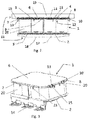
- the plating member 4 is already pre-assembled with the device 1 by means of the holding part 6, as can be seen for example in the figure 3 . In this way the alignment of the plating member 4 on the electrical device 1 is ensured.
- the electrical device 1 cannot move in undesirable directions, neither during the final assembly, nor during use.
- the plating member 4 may further comprise spring blades 22.
- the spring blades 22 extend from the surface of the plating member 4, moving away. These blades 22 generate the force exerted by the plating member 4 on the second face 5 of the electrical device 1, which will press the electrical device 1 on the surface 3 of the cooling circuit 17.
- the surface of the member plating 4 is therefore not uniform. To avoid undesirable deformations of the plating member 4, protection is preferable.
- the holding part 6 keeps the plating member 4 in place and protects it at the same time.
- the holding part 6 must therefore meet several technical requirements.
- a holding part 6 is illustrated, in general and detailed views.
- the holding piece 6 comprises a bottom wall 9 and side walls 10 extending from the bottom 9.
- the bottom 9 and the side walls 10 comprising the edge 8 of the holding piece 6.
- Drains 23 extend from the bottom 9, along the side walls 10, and protrude from the edge 8.
- the gullies 23 have an essentially triangular shape, tapering away from the bottom.
- the ends of the gullies 23 are rounded, in order to avoid snagging. As they are arranged all around the holding piece 6, a funnel effect allows easy and targeted placement during assembly of the holding piece 6 on the plating member 4 and the electrical device 1.
- the drains 23 located on one side of the holding piece 6 cooperate with drains 23 located on the opposite side of the holding piece 6. Knowing that a symmetrical distribution is not necessary, at least one drain 23 is preferable on each side. However two drains 23 per side facilitate the arrangement.
- the first fasteners 13, described below, can also act as a drain 23.
- the plating member 4 may be composed of a single spring plate 25, as illustrated in the figure 4 or it can be composed of several spring plates 25 as illustrated by the figure 8 for example.
- the holding part 6, illustrated by the figure 5 is provided to protect and encompass a plating member 4 with a single spring plate 25.
- the plating member 4 extends in this case over the entire second face 5 of the electrical device 1.
- the bottom 9 of the holding part 6 can therefore be smooth, the positioning of the plating member 4 is therefore made by the edge of the holding part 6, coming into correspondence with an edge 26 of the plating member 4.
- an insulation layer can be arranged between the plating member 4 and the electrical device 1.
- This insulating layer prevents a short circuit between the plating member 4 and the electrical device 1, in particular between the plating member 4 and the electrical conductors 14.
- the insulating layer can be a sheet of insulating material.
- the holding part 6, illustrated by the figure 6 is provided to protect and encompass a plating member 4 composed of several spring plates 25, in this case two spring plates 25.
- the spring plates 25 in this case together cover the second face 5 of the electrical device 1.
- the holding part 6 comprises protuberances 24, arranged at the gap 27 between the two spring plates 25.
- the extent of the protrusions 24 must correspond to the clearance of the fasteners 13, 15 described later.
- the positioning of the plating member 4 is then provided by the edge 8 of the holding part 6, cooperating with the edge of the plating member 26 and by the protrusions 24 cooperating with the gap 27 between the two spring plates 25.
- the assembly may be free of insulating layer electrical between the plating member 4 and the electrical device 1, in particular between the plating member 4 and the electrical conductors 14.
- the holding part 6 can provide electrical isolation of the electrical device 1 from the environment .
- the holding part 6 is then of a dielectric material.
- the retaining piece 6 fully covers the plating member 4. However, it is also possible that the retaining piece 6 only partially covers the plating member.
- fasteners 13, 15 are used to fix the holding part 6 to the electrical device 1.
- a fastener comprises in particular a first 13 and a second 15 fixing member.
- the first fixing member 13 is located on an edge 8 of the holding piece 6.
- the second fixing member 15 is located on a peripheral portion 7 of the electric device 1, in particular on an edge of the second face 5 of the electrical device 1 or around the second face 5 of the electrical device 1.
- the first fixing member 13 is in particular a protuberance extending from the bottom 9 of the retaining part 6, along the side walls 10, with a hook-shaped heel 28.
- the second fastening member 15 is in particular in the form of an eyelet 29.
- the hook 28 snaps into the eyelet 29.
- the eyelets 29 can be integrated, as illustrated by the figure 8 , directly to the electrical conductors 14. However, in the case where the electrical device 1 comprises a housing 16, as illustrated by the figure 9 , the eyelets can be integrated into this box 16. In particular, the eyelet 29 is included in the second face 5 of the electrical device 1. However, the eyelet 29 could be offset with respect to the second face 5, on a side wall of the electrical device 1.
- the figure 7 shows a fastener 13, 15 in detail.
- the hook 28 is introduced by one side of the eyelet 29 so as to fix the holding part 6 on the electrical device 1.
- the hook 28 then snaps into the eyelet 29.
- the hook 28 has a portion 31 which comes facing a fastening surface 30 of the eyelet 29.
- the portion 31 and the fastening surface 30 of the eyelet 29 cooperate to allow the hook 28 to be held in the eyelet 29.
- the retaining part 6 can therefore be more or less close to the electrical device 1, depending on the force exerted on it.
- the holding part 6 in a first position, the holding part 6 is free from any constraint coming from its outer face.
- the holding part 6 undergoes a reaction of the plating member 4, which pushes the retaining piece 6.
- the portion 31 of the hook 28 comes into contact with the attachment surface 30 and maintains the retaining piece 6 as well as the plating member 4 in position on the electrical device 1.
- the holding part 6 is then in a position distal to the electrical device 1.
- a force will be exerted on the electrical device 1, in order to clamp the first face 2 of the electrical device 1 on the surface 3 of the cooling circuit 17.
- the second part 19 of the chassis presses on the retaining part 6, in particular on the external face of the retaining part 6 opposite to the plating member 4.
- the bottom 9 of the holding part 6 approaches the electrical device 1.
- the drains 23 are in particular configured to cooperate with the peripheral portion 7 of the electrical device 1 so as to guide the holding part 6 towards the second face 5 of the electrical device 1.
- the plating member 4 is therefore compressed, allowing a plating of the first face 2 of the device 1 on the first part 18 of the chassis.
- the portion 31 of the hook 28 is no longer in contact with the attachment surface 30.
- a position proximal to the holding part 6 relative to the electrical device 1 is then obtained.
- the figure 7 illustrates the proximal position of the holding part 6.
- the holding part 6 nevertheless exerts a force on the plating member 4 in order to avoid a lateral displacement of the plating member 4. This force is then low compared to that exerted on the plating member 4 when the assembly is mounted between the two parts 18, 19 of the chassis.
Landscapes
- Engineering & Computer Science (AREA)
- Microelectronics & Electronic Packaging (AREA)
- Physics & Mathematics (AREA)
- Thermal Sciences (AREA)
- Mechanical Engineering (AREA)
- Power Engineering (AREA)
- Transportation (AREA)
- Mounting Components In General For Electric Apparatus (AREA)
- Inverter Devices (AREA)
- Casings For Electric Apparatus (AREA)
- Cooling Or The Like Of Electrical Apparatus (AREA)
Applications Claiming Priority (1)
| Application Number | Priority Date | Filing Date | Title |
|---|---|---|---|
| FR1873808A FR3091012B1 (fr) | 2018-12-21 | 2018-12-21 | Ensemble comprenant un dispositif electrique, un organe de plaquage et une piece de maintien de l’organe de plaquage |
Publications (2)
| Publication Number | Publication Date |
|---|---|
| EP3672383A1 true EP3672383A1 (de) | 2020-06-24 |
| EP3672383B1 EP3672383B1 (de) | 2022-08-03 |
Family
ID=66641089
Family Applications (1)
| Application Number | Title | Priority Date | Filing Date |
|---|---|---|---|
| EP19213493.0A Active EP3672383B1 (de) | 2018-12-21 | 2019-12-04 | Einheit, die eine elektrische vorrichtung, ein plattierorgan und ein halteelement des plattierorgans umfasst |
Country Status (5)
| Country | Link |
|---|---|
| US (1) | US11219139B2 (de) |
| EP (1) | EP3672383B1 (de) |
| JP (1) | JP7659722B2 (de) |
| CN (1) | CN111347984A (de) |
| FR (1) | FR3091012B1 (de) |
Families Citing this family (1)
| Publication number | Priority date | Publication date | Assignee | Title |
|---|---|---|---|---|
| JP7543358B2 (ja) * | 2022-09-21 | 2024-09-02 | 株式会社安川電機 | スイッチングモジュール、電力変換装置、及び、電力変換装置の製造方法 |
Citations (4)
| Publication number | Priority date | Publication date | Assignee | Title |
|---|---|---|---|---|
| JP2000223630A (ja) * | 1999-02-04 | 2000-08-11 | Sharp Corp | 金属筐体に囲まれた電子部品の放熱構造 |
| EP2172971A2 (de) * | 2008-10-01 | 2010-04-07 | Siemens AG Österreich | Kühlanordnung |
| WO2014033382A1 (fr) * | 2012-08-29 | 2014-03-06 | Valeo Systemes De Controle Moteur | Organe de plaquage d'une piece sur une surface |
| DE102013109532B3 (de) * | 2013-09-02 | 2014-08-28 | Semikron Elektronik Gmbh & Co. Kg | Leistungshalbleitereinrichtung |
Family Cites Families (21)
| Publication number | Priority date | Publication date | Assignee | Title |
|---|---|---|---|---|
| JP4099043B2 (ja) * | 2002-12-04 | 2008-06-11 | 東芝三菱電機産業システム株式会社 | 機器固定装置 |
| JP4154325B2 (ja) * | 2003-12-19 | 2008-09-24 | 株式会社日立産機システム | 電気回路モジュール |
| JP4528612B2 (ja) | 2004-12-27 | 2010-08-18 | 矢崎総業株式会社 | サーミスタ温度計の取付構造 |
| US7663227B2 (en) * | 2005-10-11 | 2010-02-16 | Macris Chris G | Liquid metal thermal interface material system |
| US20080128895A1 (en) * | 2006-12-05 | 2008-06-05 | Oman Todd P | Wafer applied thermal-mechanical interface |
| JP5028085B2 (ja) * | 2006-12-27 | 2012-09-19 | アイシン・エィ・ダブリュ株式会社 | 電子回路装置とその製造方法 |
| JP4400662B2 (ja) | 2007-09-12 | 2010-01-20 | 株式会社デンソー | 電子回路部品実装構造 |
| US7746653B2 (en) * | 2008-01-02 | 2010-06-29 | Harman International Industries Incorporated | Clamp for electrical devices |
| ES2621135T3 (es) * | 2010-07-29 | 2017-07-03 | E4V | Sistema de refrigeración de batería eléctrica y batería que comprende dicho sistema |
| FR2979961B1 (fr) * | 2011-09-12 | 2014-06-20 | Valeo Sys Controle Moteur Sas | Organe de plaquage d'une piece sur une surface |
| US9545032B2 (en) * | 2011-10-26 | 2017-01-10 | Accelerated Systems Inc. | Enclosure for an electronic assembly for a battery powered lawn mower |
| JP2013103535A (ja) * | 2011-11-10 | 2013-05-30 | Honda Elesys Co Ltd | 電動パワーステアリング用電子制御ユニット |
| JP2014166115A (ja) | 2013-02-27 | 2014-09-08 | Noritz Corp | 電力変換装置 |
| JP2015128138A (ja) | 2013-11-27 | 2015-07-09 | 株式会社豊田自動織機 | 半導体装置 |
| DE102014004262A1 (de) * | 2014-03-20 | 2015-09-24 | Ziehl-Abegg Se | Elektromotor, insbesondere Außenläufermotor, sowie Zwischenisolierteil für einen Elektromotor |
| US10128723B2 (en) * | 2015-07-07 | 2018-11-13 | Milwaukee Electric Tool Corporation | Printed circuit board spacer |
| FR3043879B1 (fr) * | 2015-11-13 | 2018-08-24 | Valeo Siemens Eautomotive France Sas | Ensemble formant boitier pour un equipement electrique |
| US11502018B2 (en) * | 2016-09-12 | 2022-11-15 | Mitsubishi Electric Corporation | Holding and ignition prevention device for semiconductor element, and power conversion device using holding and ignition prevention device |
| US9826655B1 (en) * | 2016-12-15 | 2017-11-21 | Oracle International Corporation | Method and apparatus for mounting a circuit board in an enclosure |
| DE102017112037A1 (de) * | 2017-06-01 | 2018-12-06 | Ebm-Papst Mulfingen Gmbh & Co. Kg | Bauteilhaltevorrichtung |
| US10660242B2 (en) * | 2018-04-26 | 2020-05-19 | Chongqing Jinkang New Energy Vehicle Co., Ltd. | Electric vehicle inverter module heat sink |
-
2018
- 2018-12-21 FR FR1873808A patent/FR3091012B1/fr active Active
-
2019
- 2019-12-04 EP EP19213493.0A patent/EP3672383B1/de active Active
- 2019-12-18 CN CN201911306821.7A patent/CN111347984A/zh active Pending
- 2019-12-19 US US16/720,851 patent/US11219139B2/en active Active
- 2019-12-20 JP JP2019229975A patent/JP7659722B2/ja active Active
Patent Citations (4)
| Publication number | Priority date | Publication date | Assignee | Title |
|---|---|---|---|---|
| JP2000223630A (ja) * | 1999-02-04 | 2000-08-11 | Sharp Corp | 金属筐体に囲まれた電子部品の放熱構造 |
| EP2172971A2 (de) * | 2008-10-01 | 2010-04-07 | Siemens AG Österreich | Kühlanordnung |
| WO2014033382A1 (fr) * | 2012-08-29 | 2014-03-06 | Valeo Systemes De Controle Moteur | Organe de plaquage d'une piece sur une surface |
| DE102013109532B3 (de) * | 2013-09-02 | 2014-08-28 | Semikron Elektronik Gmbh & Co. Kg | Leistungshalbleitereinrichtung |
Also Published As
| Publication number | Publication date |
|---|---|
| US11219139B2 (en) | 2022-01-04 |
| FR3091012A1 (fr) | 2020-06-26 |
| CN111347984A (zh) | 2020-06-30 |
| JP7659722B2 (ja) | 2025-04-10 |
| US20200205311A1 (en) | 2020-06-25 |
| FR3091012B1 (fr) | 2021-01-15 |
| EP3672383B1 (de) | 2022-08-03 |
| JP2020102625A (ja) | 2020-07-02 |
Similar Documents
| Publication | Publication Date | Title |
|---|---|---|
| FR3067131B1 (fr) | Dispositif optique pour vehicule comprenant un element de chauffage | |
| EP3547001A1 (de) | Optische vorrichtung für fahrzeug, die mit einem heizelement ausgestattet ist | |
| FR3082634A1 (fr) | Dispositif optique pour vehicule comprenant un element de chauffage | |
| WO2020084479A1 (fr) | Dispositif de connexion pour véhicule équipé d'un capteur de température | |
| EP2891178B1 (de) | Körper zum pressen eines teils auf eine oberfläche | |
| EP3621093A1 (de) | Kapazitiver block mit einem kühlkörper | |
| EP3672383B1 (de) | Einheit, die eine elektrische vorrichtung, ein plattierorgan und ein halteelement des plattierorgans umfasst | |
| EP3056070B1 (de) | Elektrisches modul, elektrischen system mit derartigem elektrischen modul und zugehörige herstellungsverfahren | |
| WO2002060038A1 (fr) | Connecteur electrique a contacts multiples et machine electrique tournante portant un tel connecteur | |
| FR3097095A1 (fr) | Équipement electrique comprenant un élément élastique de fixation | |
| EP3170227A1 (de) | Elektrischer verbinder und elektrisches verbindungssystem | |
| EP2745661B1 (de) | Elektrische verbindungsvorrichtung, anordnung mit einer solchen vorrichtung und elektronikplatine sowie verfahren zum elektrischen anschluss einer elektronikplatine | |
| EP3443614A1 (de) | Antennenmodul für ein kraftfahrzeug mit einem metallblech | |
| EP3836765A1 (de) | Elektrisches isolationsmodul für elektrische hochspannungsausstattung | |
| FR3074459A1 (fr) | Dispositif electrique d'organe de vehicule automobile tel qu'un volant | |
| WO2010139886A1 (fr) | Dispositif de liaison entre un connecteur electrique et un cable electrique coaxial blinde et connecteur electrique correspondant | |
| EP3895190B1 (de) | Anordnung für einen kapazitiven block mit integrierten haltegliedern | |
| WO2015071172A1 (fr) | Connecteur electrique a reprise de blindage | |
| WO2013053476A2 (fr) | Systeme de maintien mecanique, ensemble comprenant un tel systeme et une carte electronique et procede d'assemblage sur une surface d'un tel systeme et d'une telle carte | |
| FR2969775A1 (fr) | Calculateur electronique pour vehicule automobile | |
| FR3067130B1 (fr) | Dispositif optique pour vehicule | |
| FR3069964B1 (fr) | Connecteur electrique constitutif d'un compresseur electrique et compresseur electrique comprenant un tel connecteur electrique | |
| EP3811471A1 (de) | Elektrisches verbindungssystem mit einer primären verbindungsvorrichtung und einer sekundären verbindungsvorrichtung | |
| WO2024100334A1 (fr) | Attache coulissante pour barres omnibus d'un systeme de batteries de vehicule electrique et vehicule comportant une telle attache | |
| EP4576134A1 (de) | Thermische kopplungsvorrichtung für eine gleichtaktdrossel |
Legal Events
| Date | Code | Title | Description |
|---|---|---|---|
| PUAI | Public reference made under article 153(3) epc to a published international application that has entered the european phase |
Free format text: ORIGINAL CODE: 0009012 |
|
| STAA | Information on the status of an ep patent application or granted ep patent |
Free format text: STATUS: THE APPLICATION HAS BEEN PUBLISHED |
|
| AK | Designated contracting states |
Kind code of ref document: A1 Designated state(s): AL AT BE BG CH CY CZ DE DK EE ES FI FR GB GR HR HU IE IS IT LI LT LU LV MC MK MT NL NO PL PT RO RS SE SI SK SM TR |
|
| AX | Request for extension of the european patent |
Extension state: BA ME |
|
| STAA | Information on the status of an ep patent application or granted ep patent |
Free format text: STATUS: REQUEST FOR EXAMINATION WAS MADE |
|
| 17P | Request for examination filed |
Effective date: 20201217 |
|
| RBV | Designated contracting states (corrected) |
Designated state(s): AL AT BE BG CH CY CZ DE DK EE ES FI FR GB GR HR HU IE IS IT LI LT LU LV MC MK MT NL NO PL PT RO RS SE SI SK SM TR |
|
| GRAP | Despatch of communication of intention to grant a patent |
Free format text: ORIGINAL CODE: EPIDOSNIGR1 |
|
| STAA | Information on the status of an ep patent application or granted ep patent |
Free format text: STATUS: GRANT OF PATENT IS INTENDED |
|
| RIC1 | Information provided on ipc code assigned before grant |
Ipc: H05K 7/20 20060101AFI20220207BHEP |
|
| INTG | Intention to grant announced |
Effective date: 20220224 |
|
| GRAS | Grant fee paid |
Free format text: ORIGINAL CODE: EPIDOSNIGR3 |
|
| GRAA | (expected) grant |
Free format text: ORIGINAL CODE: 0009210 |
|
| STAA | Information on the status of an ep patent application or granted ep patent |
Free format text: STATUS: THE PATENT HAS BEEN GRANTED |
|
| AK | Designated contracting states |
Kind code of ref document: B1 Designated state(s): AL AT BE BG CH CY CZ DE DK EE ES FI FR GB GR HR HU IE IS IT LI LT LU LV MC MK MT NL NO PL PT RO RS SE SI SK SM TR |
|
| RIN1 | Information on inventor provided before grant (corrected) |
Inventor name: POUILLY, AURELIEN Inventor name: LEGENDRE, ALEXANDRE |
|
| REG | Reference to a national code |
Ref country code: AT Ref legal event code: REF Ref document number: 1509805 Country of ref document: AT Kind code of ref document: T Effective date: 20220815 Ref country code: CH Ref legal event code: EP |
|
| REG | Reference to a national code |
Ref country code: DE Ref legal event code: R096 Ref document number: 602019017731 Country of ref document: DE |
|
| REG | Reference to a national code |
Ref country code: IE Ref legal event code: FG4D Free format text: LANGUAGE OF EP DOCUMENT: FRENCH |
|
| RAP4 | Party data changed (patent owner data changed or rights of a patent transferred) |
Owner name: VALEO EAUTOMOTIVE FRANCE SAS |
|
| REG | Reference to a national code |
Ref country code: LT Ref legal event code: MG9D |
|
| REG | Reference to a national code |
Ref country code: NL Ref legal event code: MP Effective date: 20220803 |
|
| PG25 | Lapsed in a contracting state [announced via postgrant information from national office to epo] |
Ref country code: SE Free format text: LAPSE BECAUSE OF FAILURE TO SUBMIT A TRANSLATION OF THE DESCRIPTION OR TO PAY THE FEE WITHIN THE PRESCRIBED TIME-LIMIT Effective date: 20220803 Ref country code: RS Free format text: LAPSE BECAUSE OF FAILURE TO SUBMIT A TRANSLATION OF THE DESCRIPTION OR TO PAY THE FEE WITHIN THE PRESCRIBED TIME-LIMIT Effective date: 20220803 Ref country code: PT Free format text: LAPSE BECAUSE OF FAILURE TO SUBMIT A TRANSLATION OF THE DESCRIPTION OR TO PAY THE FEE WITHIN THE PRESCRIBED TIME-LIMIT Effective date: 20221205 Ref country code: NO Free format text: LAPSE BECAUSE OF FAILURE TO SUBMIT A TRANSLATION OF THE DESCRIPTION OR TO PAY THE FEE WITHIN THE PRESCRIBED TIME-LIMIT Effective date: 20221103 Ref country code: NL Free format text: LAPSE BECAUSE OF FAILURE TO SUBMIT A TRANSLATION OF THE DESCRIPTION OR TO PAY THE FEE WITHIN THE PRESCRIBED TIME-LIMIT Effective date: 20220803 Ref country code: LV Free format text: LAPSE BECAUSE OF FAILURE TO SUBMIT A TRANSLATION OF THE DESCRIPTION OR TO PAY THE FEE WITHIN THE PRESCRIBED TIME-LIMIT Effective date: 20220803 Ref country code: LT Free format text: LAPSE BECAUSE OF FAILURE TO SUBMIT A TRANSLATION OF THE DESCRIPTION OR TO PAY THE FEE WITHIN THE PRESCRIBED TIME-LIMIT Effective date: 20220803 Ref country code: FI Free format text: LAPSE BECAUSE OF FAILURE TO SUBMIT A TRANSLATION OF THE DESCRIPTION OR TO PAY THE FEE WITHIN THE PRESCRIBED TIME-LIMIT Effective date: 20220803 Ref country code: ES Free format text: LAPSE BECAUSE OF FAILURE TO SUBMIT A TRANSLATION OF THE DESCRIPTION OR TO PAY THE FEE WITHIN THE PRESCRIBED TIME-LIMIT Effective date: 20220803 |
|
| REG | Reference to a national code |
Ref country code: AT Ref legal event code: MK05 Ref document number: 1509805 Country of ref document: AT Kind code of ref document: T Effective date: 20220803 |
|
| PG25 | Lapsed in a contracting state [announced via postgrant information from national office to epo] |
Ref country code: PL Free format text: LAPSE BECAUSE OF FAILURE TO SUBMIT A TRANSLATION OF THE DESCRIPTION OR TO PAY THE FEE WITHIN THE PRESCRIBED TIME-LIMIT Effective date: 20220803 Ref country code: IS Free format text: LAPSE BECAUSE OF FAILURE TO SUBMIT A TRANSLATION OF THE DESCRIPTION OR TO PAY THE FEE WITHIN THE PRESCRIBED TIME-LIMIT Effective date: 20221203 Ref country code: HR Free format text: LAPSE BECAUSE OF FAILURE TO SUBMIT A TRANSLATION OF THE DESCRIPTION OR TO PAY THE FEE WITHIN THE PRESCRIBED TIME-LIMIT Effective date: 20220803 Ref country code: GR Free format text: LAPSE BECAUSE OF FAILURE TO SUBMIT A TRANSLATION OF THE DESCRIPTION OR TO PAY THE FEE WITHIN THE PRESCRIBED TIME-LIMIT Effective date: 20221104 |
|
| PG25 | Lapsed in a contracting state [announced via postgrant information from national office to epo] |
Ref country code: SM Free format text: LAPSE BECAUSE OF FAILURE TO SUBMIT A TRANSLATION OF THE DESCRIPTION OR TO PAY THE FEE WITHIN THE PRESCRIBED TIME-LIMIT Effective date: 20220803 Ref country code: RO Free format text: LAPSE BECAUSE OF FAILURE TO SUBMIT A TRANSLATION OF THE DESCRIPTION OR TO PAY THE FEE WITHIN THE PRESCRIBED TIME-LIMIT Effective date: 20220803 Ref country code: DK Free format text: LAPSE BECAUSE OF FAILURE TO SUBMIT A TRANSLATION OF THE DESCRIPTION OR TO PAY THE FEE WITHIN THE PRESCRIBED TIME-LIMIT Effective date: 20220803 Ref country code: CZ Free format text: LAPSE BECAUSE OF FAILURE TO SUBMIT A TRANSLATION OF THE DESCRIPTION OR TO PAY THE FEE WITHIN THE PRESCRIBED TIME-LIMIT Effective date: 20220803 Ref country code: AT Free format text: LAPSE BECAUSE OF FAILURE TO SUBMIT A TRANSLATION OF THE DESCRIPTION OR TO PAY THE FEE WITHIN THE PRESCRIBED TIME-LIMIT Effective date: 20220803 |
|
| REG | Reference to a national code |
Ref country code: DE Ref legal event code: R097 Ref document number: 602019017731 Country of ref document: DE |
|
| PG25 | Lapsed in a contracting state [announced via postgrant information from national office to epo] |
Ref country code: SK Free format text: LAPSE BECAUSE OF FAILURE TO SUBMIT A TRANSLATION OF THE DESCRIPTION OR TO PAY THE FEE WITHIN THE PRESCRIBED TIME-LIMIT Effective date: 20220803 Ref country code: EE Free format text: LAPSE BECAUSE OF FAILURE TO SUBMIT A TRANSLATION OF THE DESCRIPTION OR TO PAY THE FEE WITHIN THE PRESCRIBED TIME-LIMIT Effective date: 20220803 |
|
| PLBE | No opposition filed within time limit |
Free format text: ORIGINAL CODE: 0009261 |
|
| STAA | Information on the status of an ep patent application or granted ep patent |
Free format text: STATUS: NO OPPOSITION FILED WITHIN TIME LIMIT |
|
| PG25 | Lapsed in a contracting state [announced via postgrant information from national office to epo] |
Ref country code: AL Free format text: LAPSE BECAUSE OF FAILURE TO SUBMIT A TRANSLATION OF THE DESCRIPTION OR TO PAY THE FEE WITHIN THE PRESCRIBED TIME-LIMIT Effective date: 20220803 |
|
| 26N | No opposition filed |
Effective date: 20230504 |
|
| REG | Reference to a national code |
Ref country code: CH Ref legal event code: PL |
|
| P01 | Opt-out of the competence of the unified patent court (upc) registered |
Effective date: 20230629 |
|
| REG | Reference to a national code |
Ref country code: BE Ref legal event code: MM Effective date: 20221231 |
|
| PG25 | Lapsed in a contracting state [announced via postgrant information from national office to epo] |
Ref country code: SI Free format text: LAPSE BECAUSE OF FAILURE TO SUBMIT A TRANSLATION OF THE DESCRIPTION OR TO PAY THE FEE WITHIN THE PRESCRIBED TIME-LIMIT Effective date: 20220803 Ref country code: LU Free format text: LAPSE BECAUSE OF NON-PAYMENT OF DUE FEES Effective date: 20221204 |
|
| PG25 | Lapsed in a contracting state [announced via postgrant information from national office to epo] |
Ref country code: LI Free format text: LAPSE BECAUSE OF NON-PAYMENT OF DUE FEES Effective date: 20221231 Ref country code: IE Free format text: LAPSE BECAUSE OF NON-PAYMENT OF DUE FEES Effective date: 20221204 Ref country code: CH Free format text: LAPSE BECAUSE OF NON-PAYMENT OF DUE FEES Effective date: 20221231 |
|
| PG25 | Lapsed in a contracting state [announced via postgrant information from national office to epo] |
Ref country code: BE Free format text: LAPSE BECAUSE OF NON-PAYMENT OF DUE FEES Effective date: 20221231 |
|
| PG25 | Lapsed in a contracting state [announced via postgrant information from national office to epo] |
Ref country code: HU Free format text: LAPSE BECAUSE OF FAILURE TO SUBMIT A TRANSLATION OF THE DESCRIPTION OR TO PAY THE FEE WITHIN THE PRESCRIBED TIME-LIMIT; INVALID AB INITIO Effective date: 20191204 |
|
| PG25 | Lapsed in a contracting state [announced via postgrant information from national office to epo] |
Ref country code: CY Free format text: LAPSE BECAUSE OF FAILURE TO SUBMIT A TRANSLATION OF THE DESCRIPTION OR TO PAY THE FEE WITHIN THE PRESCRIBED TIME-LIMIT Effective date: 20220803 |
|
| PG25 | Lapsed in a contracting state [announced via postgrant information from national office to epo] |
Ref country code: MK Free format text: LAPSE BECAUSE OF FAILURE TO SUBMIT A TRANSLATION OF THE DESCRIPTION OR TO PAY THE FEE WITHIN THE PRESCRIBED TIME-LIMIT Effective date: 20220803 Ref country code: IT Free format text: LAPSE BECAUSE OF FAILURE TO SUBMIT A TRANSLATION OF THE DESCRIPTION OR TO PAY THE FEE WITHIN THE PRESCRIBED TIME-LIMIT Effective date: 20220803 |
|
| PG25 | Lapsed in a contracting state [announced via postgrant information from national office to epo] |
Ref country code: MC Free format text: LAPSE BECAUSE OF FAILURE TO SUBMIT A TRANSLATION OF THE DESCRIPTION OR TO PAY THE FEE WITHIN THE PRESCRIBED TIME-LIMIT Effective date: 20220803 |
|
| PG25 | Lapsed in a contracting state [announced via postgrant information from national office to epo] |
Ref country code: MC Free format text: LAPSE BECAUSE OF FAILURE TO SUBMIT A TRANSLATION OF THE DESCRIPTION OR TO PAY THE FEE WITHIN THE PRESCRIBED TIME-LIMIT Effective date: 20220803 |
|
| PG25 | Lapsed in a contracting state [announced via postgrant information from national office to epo] |
Ref country code: BG Free format text: LAPSE BECAUSE OF FAILURE TO SUBMIT A TRANSLATION OF THE DESCRIPTION OR TO PAY THE FEE WITHIN THE PRESCRIBED TIME-LIMIT Effective date: 20220803 |
|
| PG25 | Lapsed in a contracting state [announced via postgrant information from national office to epo] |
Ref country code: MT Free format text: LAPSE BECAUSE OF FAILURE TO SUBMIT A TRANSLATION OF THE DESCRIPTION OR TO PAY THE FEE WITHIN THE PRESCRIBED TIME-LIMIT Effective date: 20220803 |
|
| PG25 | Lapsed in a contracting state [announced via postgrant information from national office to epo] |
Ref country code: TR Free format text: LAPSE BECAUSE OF FAILURE TO SUBMIT A TRANSLATION OF THE DESCRIPTION OR TO PAY THE FEE WITHIN THE PRESCRIBED TIME-LIMIT Effective date: 20220803 |
|
| PGFP | Annual fee paid to national office [announced via postgrant information from national office to epo] |
Ref country code: GB Payment date: 20251229 Year of fee payment: 7 |
|
| PGFP | Annual fee paid to national office [announced via postgrant information from national office to epo] |
Ref country code: FR Payment date: 20251230 Year of fee payment: 7 |
|
| PGFP | Annual fee paid to national office [announced via postgrant information from national office to epo] |
Ref country code: DE Payment date: 20251231 Year of fee payment: 7 |