EP3673133B1 - Antriebsvorrichtung für eine fahrzeugklappe - Google Patents
Antriebsvorrichtung für eine fahrzeugklappe Download PDFInfo
- Publication number
- EP3673133B1 EP3673133B1 EP18765549.3A EP18765549A EP3673133B1 EP 3673133 B1 EP3673133 B1 EP 3673133B1 EP 18765549 A EP18765549 A EP 18765549A EP 3673133 B1 EP3673133 B1 EP 3673133B1
- Authority
- EP
- European Patent Office
- Prior art keywords
- drive device
- control device
- switching element
- switch control
- designed
- Prior art date
- Legal status (The legal status is an assumption and is not a legal conclusion. Google has not performed a legal analysis and makes no representation as to the accuracy of the status listed.)
- Active
Links
Images

Classifications
-
- E—FIXED CONSTRUCTIONS
- E05—LOCKS; KEYS; WINDOW OR DOOR FITTINGS; SAFES
- E05F—DEVICES FOR MOVING WINGS INTO OPEN OR CLOSED POSITION; CHECKS FOR WINGS; WING FITTINGS NOT OTHERWISE PROVIDED FOR, CONCERNED WITH THE FUNCTIONING OF THE WING
- E05F15/00—Power-operated mechanisms for wings
- E05F15/60—Power-operated mechanisms for wings using electrical actuators
- E05F15/603—Power-operated mechanisms for wings using electrical actuators using rotary electromotors
-
- E—FIXED CONSTRUCTIONS
- E05—LOCKS; KEYS; WINDOW OR DOOR FITTINGS; SAFES
- E05F—DEVICES FOR MOVING WINGS INTO OPEN OR CLOSED POSITION; CHECKS FOR WINGS; WING FITTINGS NOT OTHERWISE PROVIDED FOR, CONCERNED WITH THE FUNCTIONING OF THE WING
- E05F15/00—Power-operated mechanisms for wings
- E05F15/60—Power-operated mechanisms for wings using electrical actuators
- E05F15/603—Power-operated mechanisms for wings using electrical actuators using rotary electromotors
- E05F15/611—Power-operated mechanisms for wings using electrical actuators using rotary electromotors for swinging wings
-
- H—ELECTRICITY
- H02—GENERATION; CONVERSION OR DISTRIBUTION OF ELECTRIC POWER
- H02H—EMERGENCY PROTECTIVE CIRCUIT ARRANGEMENTS
- H02H7/00—Emergency protective circuit arrangements specially adapted for specific types of electric machines or apparatus or for sectionalised protection of cable or line systems, and effecting automatic switching in the event of an undesired change from normal working conditions
- H02H7/08—Emergency protective circuit arrangements specially adapted for specific types of electric machines or apparatus or for sectionalised protection of cable or line systems, and effecting automatic switching in the event of an undesired change from normal working conditions for dynamo-electric motors
- H02H7/085—Emergency protective circuit arrangements specially adapted for specific types of electric machines or apparatus or for sectionalised protection of cable or line systems, and effecting automatic switching in the event of an undesired change from normal working conditions for dynamo-electric motors against excessive load
- H02H7/0851—Emergency protective circuit arrangements specially adapted for specific types of electric machines or apparatus or for sectionalised protection of cable or line systems, and effecting automatic switching in the event of an undesired change from normal working conditions for dynamo-electric motors against excessive load for motors actuating a movable member between two end positions, e.g. detecting an end position or obstruction by overload signal
-
- H—ELECTRICITY
- H02—GENERATION; CONVERSION OR DISTRIBUTION OF ELECTRIC POWER
- H02P—CONTROL OR REGULATION OF ELECTRIC MOTORS, ELECTRIC GENERATORS OR DYNAMO-ELECTRIC CONVERTERS; CONTROLLING TRANSFORMERS, REACTORS OR CHOKE COILS
- H02P3/00—Arrangements for stopping or slowing electric motors, generators, or dynamo-electric converters
- H02P3/06—Arrangements for stopping or slowing electric motors, generators, or dynamo-electric converters for stopping or slowing an individual dynamo-electric motor or dynamo-electric converter
- H02P3/18—Arrangements for stopping or slowing electric motors, generators, or dynamo-electric converters for stopping or slowing an individual dynamo-electric motor or dynamo-electric converter for stopping or slowing an AC motor
-
- E—FIXED CONSTRUCTIONS
- E05—LOCKS; KEYS; WINDOW OR DOOR FITTINGS; SAFES
- E05Y—INDEXING SCHEME ASSOCIATED WITH SUBCLASSES E05D AND E05F, RELATING TO CONSTRUCTION ELEMENTS, ELECTRIC CONTROL, POWER SUPPLY, POWER SIGNAL OR TRANSMISSION, USER INTERFACES, MOUNTING OR COUPLING, DETAILS, ACCESSORIES, AUXILIARY OPERATIONS NOT OTHERWISE PROVIDED FOR, APPLICATION THEREOF
- E05Y2400/00—Electronic control; Electrical power; Power supply; Power or signal transmission; User interfaces
- E05Y2400/10—Electronic control
- E05Y2400/30—Electronic control of motors
- E05Y2400/3013—Electronic control of motors during manual wing operation
-
- E—FIXED CONSTRUCTIONS
- E05—LOCKS; KEYS; WINDOW OR DOOR FITTINGS; SAFES
- E05Y—INDEXING SCHEME ASSOCIATED WITH SUBCLASSES E05D AND E05F, RELATING TO CONSTRUCTION ELEMENTS, ELECTRIC CONTROL, POWER SUPPLY, POWER SIGNAL OR TRANSMISSION, USER INTERFACES, MOUNTING OR COUPLING, DETAILS, ACCESSORIES, AUXILIARY OPERATIONS NOT OTHERWISE PROVIDED FOR, APPLICATION THEREOF
- E05Y2400/00—Electronic control; Electrical power; Power supply; Power or signal transmission; User interfaces
- E05Y2400/10—Electronic control
- E05Y2400/30—Electronic control of motors
- E05Y2400/302—Electronic control of motors during electric motor braking
-
- E—FIXED CONSTRUCTIONS
- E05—LOCKS; KEYS; WINDOW OR DOOR FITTINGS; SAFES
- E05Y—INDEXING SCHEME ASSOCIATED WITH SUBCLASSES E05D AND E05F, RELATING TO CONSTRUCTION ELEMENTS, ELECTRIC CONTROL, POWER SUPPLY, POWER SIGNAL OR TRANSMISSION, USER INTERFACES, MOUNTING OR COUPLING, DETAILS, ACCESSORIES, AUXILIARY OPERATIONS NOT OTHERWISE PROVIDED FOR, APPLICATION THEREOF
- E05Y2400/00—Electronic control; Electrical power; Power supply; Power or signal transmission; User interfaces
- E05Y2400/10—Electronic control
- E05Y2400/40—Control units therefor
-
- E—FIXED CONSTRUCTIONS
- E05—LOCKS; KEYS; WINDOW OR DOOR FITTINGS; SAFES
- E05Y—INDEXING SCHEME ASSOCIATED WITH SUBCLASSES E05D AND E05F, RELATING TO CONSTRUCTION ELEMENTS, ELECTRIC CONTROL, POWER SUPPLY, POWER SIGNAL OR TRANSMISSION, USER INTERFACES, MOUNTING OR COUPLING, DETAILS, ACCESSORIES, AUXILIARY OPERATIONS NOT OTHERWISE PROVIDED FOR, APPLICATION THEREOF
- E05Y2400/00—Electronic control; Electrical power; Power supply; Power or signal transmission; User interfaces
- E05Y2400/10—Electronic control
- E05Y2400/44—Sensors not directly associated with the wing movement
- E05Y2400/445—Switches
-
- E—FIXED CONSTRUCTIONS
- E05—LOCKS; KEYS; WINDOW OR DOOR FITTINGS; SAFES
- E05Y—INDEXING SCHEME ASSOCIATED WITH SUBCLASSES E05D AND E05F, RELATING TO CONSTRUCTION ELEMENTS, ELECTRIC CONTROL, POWER SUPPLY, POWER SIGNAL OR TRANSMISSION, USER INTERFACES, MOUNTING OR COUPLING, DETAILS, ACCESSORIES, AUXILIARY OPERATIONS NOT OTHERWISE PROVIDED FOR, APPLICATION THEREOF
- E05Y2900/00—Application of doors, windows, wings or fittings thereof
- E05Y2900/50—Application of doors, windows, wings or fittings thereof for vehicles
- E05Y2900/53—Type of wing
- E05Y2900/531—Doors
-
- E—FIXED CONSTRUCTIONS
- E05—LOCKS; KEYS; WINDOW OR DOOR FITTINGS; SAFES
- E05Y—INDEXING SCHEME ASSOCIATED WITH SUBCLASSES E05D AND E05F, RELATING TO CONSTRUCTION ELEMENTS, ELECTRIC CONTROL, POWER SUPPLY, POWER SIGNAL OR TRANSMISSION, USER INTERFACES, MOUNTING OR COUPLING, DETAILS, ACCESSORIES, AUXILIARY OPERATIONS NOT OTHERWISE PROVIDED FOR, APPLICATION THEREOF
- E05Y2900/00—Application of doors, windows, wings or fittings thereof
- E05Y2900/50—Application of doors, windows, wings or fittings thereof for vehicles
- E05Y2900/53—Type of wing
- E05Y2900/546—Tailboards, tailgates or sideboards opening upwards
Definitions
- the invention relates to a drive device for a vehicle flap.
- the invention further relates to a vehicle with a drive device for a vehicle flap.
- Drive devices for vehicle flaps are known in practice, which enable the vehicle flap to be opened or closed automatically. Such drive devices are often switched from a standby mode to an operating mode via a remote control or optical sensors. Such drive devices have a motor, which is usually an electric motor. The electric motor is expediently supplied with energy from the vehicle's internal power supply and is coupled to a gear that is connected to one or more mechanical adjustment elements.
- the drive device is usually designed as a linear drive, in particular as a spindle drive. Linear drives have the advantage that they are very simply constructed and easy to control. The motor rotates one of the spindle nut and spindle rod, so that two opposing housing parts of the drive device, which are each connected to the spindle nut or the spindle rod, move relative to one another.
- WO 2015/177295 A1 shows a drive device for a vehicle flap, in particular for a motor-driven door of a towing vehicle, comprising an electric motor for driving the vehicle flap and a supply circuit with a first voltage source for supplying power to the electric motor, a first electrical supply line and a second electrical supply line, the first voltage source being arranged between the first electrical supply line and the second electrical supply line.
- the drive device shown also comprises a control circuit with a switching control device and a switching element and a diode, which are connected between the first electrical supply line and the second electrical supply line.
- the switching element and the diode are connected in series.
- the switching element is formed by a transistor or by a Darlington circuit of transistors.
- the disadvantage is that the supply circuit or the control circuit is relatively complex with a large number of components and additional resistors, which can increase the susceptibility to errors accordingly.
- EP 1 783 309 A1 shows a drive device comprising a DC motor and a supply circuit with a first voltage source for supplying power to the DC motor, a first electrical supply line and a second electrical supply line, wherein the first voltage source is arranged between the first electrical supply line and the second electrical supply line.
- the drive device further comprises a switching control device, wherein two switching elements connected in series and two Zener diodes connected in series, each oriented in opposite forward directions, are connected in parallel to one another between the first electrical supply line and the second electrical supply line.
- a disadvantage of the drive device shown is that the drive device moves essentially only in a dampened manner between two end positions when the power supply is interrupted or the switching element is opened, since the Zener diodes used only switch through up to the corresponding blocking voltage and thus a short circuit with a corresponding braking effect occurs.
- EN 10 2009 042 456 B4 shows a drive device for a pivotable vehicle flap, wherein the drive device is designed as a linear drive.
- the drive device comprises an electric motor which is operated or controlled by a control device.
- the control device comprises a control and safety circuit which is arranged on an electronic circuit board, which in turn is fastened in a housing tube of the drive device.
- the drive device further comprises a first electrical supply line and a second electrical supply line for the electric motor, wherein a switching element designed as a triac is connected in parallel to the motor and the gate of the triac is connected to the first electrical supply line 51 via a high-resistance resistor and a diode.
- a switching element designed as a triac is connected in parallel to the motor and the gate of the triac is connected to the first electrical supply line 51 via a high-resistance resistor and a diode.
- EN 10 2015 112 807 A1 shows a drive device with a direct current motor, which is supplied with power via a first electrical supply line and a second electrical supply line.
- a transistor and several resistors are arranged parallel to the direct current motor between the first electrical supply line and the second electrical supply line.
- a varistor and a resistor are connected in parallel to the transistor, so that when a certain voltage value is exceeded between the first electrical supply line and the second electrical supply line, a short-term short circuit of the motor or the voltage source. This causes the motor to brake.
- the disadvantage of the drive device shown is that it is Overloading of the motor generates braking, but does not provide deceleration in the event of a power failure. Furthermore, deceleration is caused in both pivoting directions of the vehicle flap.
- manual pivoting should be possible at least in one direction even in the event of a voltage drop in the vehicle.
- a drive device for a pivotable vehicle flap comprising an electric motor for driving the vehicle flap and a supply circuit.
- the supply circuit comprises a first voltage source for supplying power to the electric motor, a first electrical supply line and a second electrical supply line, wherein the first voltage source is arranged between the first electrical supply line and the second electrical supply line.
- the drive device further comprises a control circuit, comprising a logic unit, a second voltage source and a switching control device, wherein a switching element and a diode are connected between the first electrical supply line and the second electrical supply line and the switching element and the diode are connected in series.
- the switching element is connected to the Switching control device.
- the switching control device also provides a control voltage for switching the switching element.
- the drive device is characterized in that the logic unit is connected in parallel to the switching control device, with the second voltage source supplying both the logic unit and the switching control device with power.
- the provision of a logic unit advantageously makes it possible to evaluate external parameters over a certain period of time. It is also advantageous to regulate the power supply of the switching control device even for a voltage drop in the voltage source so that the switching element coupled to the switching control device 3 is closed.
- a short circuit of the electric motor can advantageously be implemented particularly reliably and easily. This can be particularly advantageous in an accident situation when the power supply in the vehicle has failed and the occupants want to open the door in the opening direction as easily as possible. It is advantageous to short-circuit the first electrical supply line and the second electrical supply line to the electric motor, with the diode ensuring that the electric motor is braked in one direction of rotation and can largely rotate freely in the opposite direction of rotation.
- the diode is arranged in the forward direction in the direction from the first electrical supply line to the second electrical supply line. In an alternative embodiment, the diode is arranged in the reverse direction in the direction from the first electrical supply line to the second electrical supply line.
- the diode is particularly preferably arranged between the first electrical supply line and the second electrical supply line in such a way that the drive device is braked in the closing direction in the event of a short circuit. This advantageously ensures that a person is protected in the event of a malfunction of the Power supply of the drive device can open the vehicle door without the vehicle door moving back in the closing direction due to its own weight.
- the switching control device is designed as a relay.
- a short circuit of the electric motor can be implemented particularly reliably and easily.
- the switching element coupled to the switching control device is designed as a normally closed contact.
- a normally closed contact is characterized by the fact that the switching element is in a closed position when the control coil is not loaded. In this way, in the event of a power failure in the drive device, braking of the electric motor is implemented in at least one direction.
- the switching element coupled to the switching control device is designed as a changeover contact. This advantageously makes it possible to short-circuit the electric motor even in the event of a voltage drop, without the voltage in the vehicle or in the drive device having to drop completely. It is also possible to use the voltage peaks that occur during a voltage drop to switch the switching element.
- the switching element is designed as a bipolar transistor.
- the base of the transistor is expediently connected to the switching control device.
- the switching control device advantageously provides a control voltage between the base and collector of the transistor.
- the switching control device can thus advantageously be used to specifically control the transistor.
- the provision of a transistor advantageously enables the braking force to be graduated during manual pivoting of the vehicle flap.
- the transistor is designed as an npn transistor.
- the transistor is designed as a pnp transistor.
- both negative and positive control voltages can be used to switch the transistor, depending on the design of the switching control device.
- the switching element is designed as a unipolar transistor.
- the gate of the unipolar transistor is expediently connected to the switching control device.
- the switching control device expediently provides a control voltage to the gate. This advantageously makes it possible for the switching control device to enable more targeted braking depending on external parameters.
- the external parameters can be, for example, the current opening angle of the vehicle flap or the acceleration or speed of the vehicle flap while pivoting.
- the external parameters can also be optical signals, such as the distance of an obstacle to the vehicle flap. This advantageously prevents the obstacle from colliding with the vehicle flap when it is opened and causing damage.
- the optical signals can be detected by an optical element such as a camera and converted by the switching control device into the corresponding control voltage at the gate or the switching element.
- the logic unit is expediently coupled to the switching control device. This allows the switching control device and thus the switching element coupled to the switching control device to be controlled depending on external parameters.
- the external parameters can advantageously be evaluated using evaluation electronics, which can be used to connect the control circuit.
- the diode is particularly preferably designed as a freewheeling diode. Freewheeling diodes are usually used as protection against overvoltage, whereby the threshold voltage at which a current flows through the diode in the forward direction is typically between 0.3 V and 0.7 V, depending on the semiconductor element.
- the electric motor is designed as a direct current motor.
- the electric motor is advantageously braked by self-induction if the electrical supply lines are short-circuited.
- the electric motor is designed as a brushless direct current motor.
- the direct current motor is expediently designed in such a way that a mechanical inverter is included.
- the direct current motor particularly preferably comprises a permanent magnet, between the two poles of which a rotor, which comprises a coil, is arranged. In this case, a speed-dependent alternating current is generated in the rotor of the direct current motor.
- a short circuit in the voltage supply of the direct current motor can convert it into a direct current generator, which, in the event of an external mechanical movement of the rotor, generates a braking force based on Lenz's law against the externally mechanically forced movement of the rotor.
- a diode is also connected in parallel in the supply circuit of the direct current motor ensures that the braking effect of the direct current motor effectively only occurs in one direction of rotation.
- a vehicle comprising a vehicle flap, wherein the vehicle flap is pivotably arranged on a vehicle body part.
- the vehicle further comprises a drive device, wherein the drive device is pivotably coupled with a first end to one of the vehicle flap and the vehicle body part and with a second end to the other of the vehicle flap and the vehicle body part.
- the vehicle is characterized in that the drive device is as described above is trained.
- Fig.1 shows schematically a first embodiment of a drive device 1, wherein the drive device 1 comprises a motor 2.
- the motor 2 is designed as a direct current motor, which is supplied with power via a supply circuit 3.
- the supply circuit 3 comprises a first electrical supply line 4 and a second electrical supply line 5, which are connected to a commutator 6 of the electric motor 2.
- the commutator 6 is in turn connected to a coil 7, which is rotatably mounted.
- the rotatable coil 7 is surrounded by a permanent magnet 8.
- the first electrical supply line 4 and the second electrical supply line 5 are connected to a first voltage source 9, so that the direction of current in the coil 7 depends on the currently existing angle of rotation of the coil 7 relative to the stationary commutator 6.
- the diode 11 is arranged in the forward direction in the direction from the first electrical supply line 4 to the second electrical supply line 5. This makes it possible to short-circuit the motor 2 or the two electrical supply lines 4, 5, so that the direct current motor 2 becomes a direct current generator and thus develops a braking effect against an externally forced mechanical movement in at least one direction of rotation.
- the switching element 10 is switched externally via a switching control circuit 12.
- the switching control circuit 12 comprises a switching control device 13 designed as a relay, which leaves the switching element 10 designed as a normally closed contact in an open state during normal operation of the drive device 1 and brings it into a closed position in the event of a fault or a voltage drop in the drive device 1.
- the switching control circuit 12 further comprises a second voltage source 14 and a logic unit 15, wherein the voltage source 14 supplies both the logic unit 15 and the switching control device 13 with power.
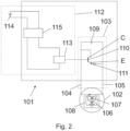
- Fig.2 shows schematically a second embodiment of a drive device 101.
- the reference numerals of similar or identical components compared to the Fig.1 shown embodiment are incremented by 100.
- the supply circuit 103 comprises a switching element 110 which is connected between the first electrical supply line 104 and the second electrical supply line 105 in parallel to the motor 102 and is designed as a bipolar transistor.
- a diode 111 is connected in series with the bipolar transistor 110, as in the first embodiment of Fig.1 .
- the bipolar transistor 110 is designed as an npn transistor, wherein the base B is connected to a switching control device 113.
- the switching control device 113 is part of a switching control circuit 112, wherein a logic unit 115 is connected in parallel to the switching control device 113.
- the switching control circuit 113 further comprises a voltage supply 114, which supplies both the logic unit 115 and the switching control device 113 with power.
- the switching control device 113 provides a control voltage at the base B of the bipolar transistor 110, so that the electrical resistance between the first electrical supply line 104 and the second electrical supply line 105 can be regulated via the switching control device 113.
- the first supply line 104 is connected to the collector C and the diode 110 to the emitter E of the bipolar transistor 110. This creates the possibility of short-circuiting the first supply line 104 and the second electrical supply line 105 by means of the control voltage provided by the switching control device 113, which is applied to the base B.
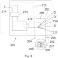
- Fig.3 shows a third embodiment of a drive device 201.
- the drive device 201 is essentially similar to the one shown in Fig.2 shown second embodiment, wherein the switching element 210 designed as a transistor is now designed as a unipolar transistor or MOSFET.
- the gate G of the transistor 210 is coupled to the switching control device 213, wherein the switching control device 213 provides a control voltage to the gate G and thus controls the electrical resistance.
- the source connection S is connected to the diode 211 and the drain connection D is connected to the first electrical supply line 204.
- Fig.1 shows the drive device 1 during normal operation.
- the switching element 10 is in an open position so that the motor 2 can be supplied with power via the supply circuit 3.
- the switching element 10 designed as a normally closed contact is brought into the closed position shown in dashed lines via the switching control device 13 designed as a relay, so that the first electrical supply line 4 and the second electrical supply line 5 are short-circuited at least in the direction from the first electrical supply line 4 to the second electrical supply line 5 via the diode 11.
- This state corresponds to a fail-safe mode, as is provided in the event of a power failure in the vehicle or even damage to the drive device 1.
- the diode 11 designed as a freewheeling diode, is connected in the forward direction in the direction from the first electrical supply line 4 to the second electrical supply line 5, so that the drive device 1 or the motor 2 is braked or locked in the closing direction of the vehicle flap and at the same time can be moved manually in the opening direction of the vehicle flap without great resistance.
- This makes it possible for the user to open a vehicle flap designed as a side door, for example, when the vehicle is on a hill and the side door must be prevented from falling back into the lock due to the large gravitational moment.
Landscapes
- Engineering & Computer Science (AREA)
- Power Engineering (AREA)
- Power-Operated Mechanisms For Wings (AREA)
- Control Of Direct Current Motors (AREA)
Description
- Die Erfindung betrifft eine Antriebsvorrichtung für eine Fahrzeugklappe. Ferner betrifft die Erfindung ein Fahrzeug mit einer Antriebsvorrichtung für eine Fahrzeugklappe.
- Aus der Praxis sind Antriebsvorrichtungen für Fahrzeugklappen bekannt, welche ein automatisches Öffnen bzw. Schließen der Fahrzeugklappe ermöglichen. Derartige Antriebsvorrichtungen werden dabei oft über eine Fernbedienung oder auch optische Sensoren von einem Standby-Modus in einen Betriebsmodus geschaltet. Dabei weisen derartige Antriebsvorrichtungen einen Motor auf, welcher meist ein Elektromotor ist. Der Elektromotor wird zweckmäßigerweise von der internen Stromversorgung des Fahrzeugs mit Energie versorgt und ist mit einem Getriebe gekoppelt, welches mit einem oder mehreren mechanischen Verstell-Elementen verbunden ist. Die Antriebsvorrichtung ist üblicherweise als Linearantrieb, insbesondere als Spindelantrieb, ausgebildet. Linearantriebe haben dabei den Vorteil, dass diese sehr einfach aufgebaut sind und leicht steuerbar sind. Der Motor treibt dabei eines von Spindelmutter und Spindelstange drehend an, sodass zwei sich gegenüberliegende Gehäuseteile der Antriebsvorrichtung, welche jeweils mit der Spindelmutter bzw. der Spindelstange verbunden sind, sich relativ zueinander bewegen.
- Neben der Funktion, dass die Fahrzeugklappe automatisch geschlossen bzw. geöffnet werden soll, kommt derartigen Antriebsvorrichtungen oftmals auch die Funktion eines Türfeststellers zu, welcher die Tür abbremsen oder feststellen soll. Ein Abbremsen der angetriebenen Fahrzeugklappe erfolgt meist durch Einsatz einer permanenten Bremse, welche auf den Antriebsstrang der Antriebsvorrichtung einwirkt. Es ist aus der Praxis bekannt, dass der Elektromotor selbsthemmend ausgebildet sein kann, sodass der Elektromotor selbst als mechanische Bremse auf eine Verschwenkungsbewegung der Fahrzeugklappe einwirkt. Dennoch treten in bestimmten Situationen überhöhte Kräfte an der Fahrzeugklappe insbesondere in Schließrichtung auf, wobei die üblichen Maßnahmen wie vorstehend beschrieben oft nicht ausreichen, um eine genügend große Haltekraft insbesondere im Fall eines Spannungsabfalls bereitzustellen.
-
WO 2015/177295 A1 zeigt eine Antriebsvorrichtung für eine Fahrzeugklappe, insbesondere für eine motorgetriebene Tür eines Zugfahrzeugs, umfassend einen Elektromotor zum Antrieb der Fahrzeugklappe und einen Versorgungsschaltkreis mit einer ersten Spannungsquelle zur Stromversorgung des Elektromotors, einer ersten elektrischen Zuleitung und einer zweiten elektrischen Zuleitung, wobei die erste Spannungsquelle zwischen der ersten elektrischen Zuleitung und der zweiten elektrischen Zuleitung angeordnet ist. Weiter umfasst die gezeigte Antriebsvorrichtung einen Steuerungsschaltkreis mit einer Schaltsteuervorrichtung und einem Schaltelement und einer Diode, welche zwischen der ersten elektrischen Zuleitung und der zweiten elektrischen Zuleitung angeschlossen sind. Dabei sind das Schaltelement und die Diode in Reihe geschaltet. Das Schaltelement wird dabei durch einen Transistor bzw. durch eine Darlingtonschaltung von Transistoren gebildet. Nachteilig ist der Versorgungsschaltkreis bzw. der Steuerungsschaltkreis relativ aufwendig mit sehr vielen Bauteilen und zusätzlichen Widerständen ausgestaltet, was die Fehleranfälligkeit entsprechend erhöhen kann. -
EP 1 783 309 A1 zeigt eine Antriebsvorrichtung, umfassend einen Gleichstrommotor und einen Versorgungsschaltkreis mit einer ersten Spannungsquelle zur Stromversorgung des Gleichstrommotors, einer ersten elektrischen Zuleitung und einer zweiten elektrischen Zuleitung, wobei die erste Spannungsquelle zwischen der ersten elektrischen Zuleitung und der zweiten elektrischen Zuleitung angeordnet ist. Weiter umfasst die Antriebsvorrichtung eine Schaltsteuervorrichtung, wobei zwei in Reihe geschaltete Schaltelemente und zwei in Reihe geschaltete jeweils in entgegengesetzte Durchlassrichtungen orientierte Zenerdioden zwischen der ersten elektrischen Zuleitung und der zweiten elektrischen Zuleitung parallel zueinander angeschlossen sind. Nachteilig an der gezeigten Antriebsvorrichtung ist, dass die Antriebsvorrichtung durch die gezeigte Schaltsteuervorrichtung bei Wegfall der Stromversorgung bzw. dem Öffnen des Schaltelementes im Wesentlichen nur gedämpft zwischen zwei Endposition verfährt, da die verwendeten Zenerdioden nur bis zu der entsprechenden Sperrspannung durchschalten und somit ein Kurzschluss mit entsprechender Bremswirkung vorliegt.DE 10 2009 042 456 B4 zeigt eine Antriebsvorrichtung für eine schwenkbare Fahrzeugklappe, wobei die Antriebsvorrichtung als Linearantrieb ausgebildet ist. Die Antriebsvorrichtung umfasst einen Elektromotor, welcher über eine Steuerungsvorrichtung betrieben bzw. gesteuert wird. Die Steuerungsvorrichtung umfasst eine Steuerungs- und Sicherheitsschaltung, welche auf einer Elektronikplatine angeordnet ist, welche wiederum in einem Gehäuserohr der Antriebsvorrichtung befestigt ist. Die Antriebsvorrichtung umfasst weiter eine erste elektrische Zuleitung und eine zweite elektrische Zuleitung für den Elektromotor, wobei ein als Triac ausgebildetes Schaltelement parallel zu dem Motor geschaltet ist und das Gate des Triacs über einen hochohmigen Widerstand und eine Diode mit der ersten elektrischen Zuleitung 51 verbunden ist.. Nachteilig an der gezeigten Antriebsvorrichtung ist, dass die Steuerung- und Sicherheitsschaltung sehr viele einzelne Bauteile umfasst, sodass die Antriebsvorrichtung entsprechend wartungsintensiv und fehleranfällig ist. Zudem sind die Kosten bei der Herstellung der Antriebsvorrichtung entsprechend hoch. -
DE 10 2015 112 807 A1 zeigt eine Antriebsvorrichtung mit einem Gleichstrommotor, welcher über eine erste elektrische Zuleitung und eine zweite elektrische Zuleitung mit Strom versorgt wird. Parallel zu dem Gleichstrommotor sind zwischen der ersten elektrischen Zuleitung und der zweiten elektrischen Zuleitung ein Transistor und mehrere Widerstände angeordnet. Weiter ist ein Varistor und ein Widerstand parallel zu dem Transistor geschaltet, sodass bei Überschreiten eines bestimmten Spannungswertes zwischen der ersten elektrischen Zuleitung und der zweiten elektrischen Zuleitung ein kurzzeitiger Kurzschluss des Motors bzw. der Spannungsquelle erfolgt. Hierdurch wird ein Abbremsen des Motors bewirkt. Nachteilig an der gezeigten Antriebsvorrichtung ist, dass diese zwar bei einer Überbeanspruchung des Motors eine Bremsung erzeugt, jedoch keine Abbremsung bei einen Ausfall der Stromversorgung bereitstellt. Weiter wird eine Abbremsung in beiden Verschwenkungsrichtungen der Fahrzeugklappe bewirkt. Dies ist jedoch insbesondere nachteilig in solchen Situation, bei denen die Fahrzeugklappe in Schließrichtung durch äußere Kräfte, insbesondere der eigenen Gewichtskraft, vorbelastet ist. Hierdurch wird es deutlich erschwert, eine Fahrzeugklappe in einer Notsituation schnell zu öffnen und gleichzeitig zu verhindern, dass die Fahrzeugklappe wieder in Schließrichtung zurückbewegt wird. - Es ist die Aufgabe der Erfindung, eine Antriebsvorrichtung für eine schwenkbare Fahrzeugklappe bzw. ein Fahrzeug anzugeben, welche ein zuverlässiges und sicheres Verschwenken der Fahrzeugklappe erlauben. Insbesondere soll ein manuelles Verschwenken auch im Falle eines Spannungsabfalls im Fahrzeug zumindest in einer Richtung möglich sein.
- Die vorgenannte Aufgabe wird erfindungsgemäß durch eine Antriebsvorrichtung mit den Merkmalen des Patentanspruchs 1 bzw. durch ein Fahrzeug gemäß Patentanspruch 14 gelöst.
- Gemäß einem Aspekt der Erfindung ist eine Antriebsvorrichtung für eine schwenkbare Fahrzeugklappe geschaffen, umfassend einen Elektromotor zum Antrieb der Fahrzeugklappe und einen Versorgungsschaltkreis. Der Versorgungsschaltkreis umfasst eine erste Spannungsquelle zur Stromversorgung des Elektromotors, eine erste elektrische Zuleitung und eine zweite elektrische Zuleitung, wobei die erste Spannungsquelle zwischen der ersten elektrischen Zuleitung und der zweiten elektrischen Zuleitung angeordnet ist. Weiter umfasst die Antriebsvorrichtung einen Steuerungsschaltkreis, umfassend eine Logikeinheit, eine zweite Spannungsquelle und eine Schaltsteuervorrichtung, wobei ein Schaltelement und eine Diode zwischen der ersten elektrischen Zuleitung und der zweiten elektrischen Zuleitung angeschlossen sind und das Schaltelement und die Diode in Reihe geschaltet sind. Das Schaltelement ist dabei mit der Schaltsteuervorrichtung gekoppelt. Weiter stellt die Schaltsteuervorrichtung eine Steuerspannung zum Schalten des Schaltelements bereit. Vorteilhaft wird hierdurch ermöglicht, den Kurzschluss des Elektromotors und damit die Abbremsung desselben in Abhängigkeit äußerer Zustände, beispielsweise dem Zustand der Spannungsversorgung der Schaltvorrichtung bzw. der Spannungsversorgung des Elektromotors, erfolgen zu lassen. Die erfindungsgemäße Antriebsvorrichtung zeichnet sich dadurch aus, dass die Logikeinheit parallel zu der Schaltsteuervorrichtung geschaltet ist, wobei die zweite Spannungsquelle sowohl die Logikeinheit als auch die Schaltsteuervorrichtung mit Strom versorgt. Vorteilhaft wird es durch das Vorsehen einer Logikeinheit ermöglicht, eine Auswertung äußerer Parameter über eine gewisse Zeitspanne vorzunehmen. Weiter vorteilhaft wird es ermöglicht, die Stromversorgung der Schaltsteuervorrichtung auch für einen Spannungsabfall der Spannungsquelle so zu regulieren, dass das mit der Schaltsteuervorrichtung 3 gekoppelte Schaltelement geschlossen wird Weiter vorteilhaft wird durch die Antriebsvorrichtung bzw. das Vorsehen eines Schaltelementes und einer Diode in dem Versorgungsschaltkreis ein zuverlässiges und sicheres Verschwenken der Fahrzeugklappe in Öffnungsrichtung bzw. Schließrichtung ermöglicht, wobei die Antriebsvorrichtung in der jeweils entgegengesetzte Schwenkrichtung durch Kurzschluss des Elektromotors abgebremst bzw. die Fahrzeugklappe gehalten wird. Vorteilhaft kann ein Kurzschluss des Elektromotors besonders zuverlässig und einfach realisiert werden. Besonders vorteilhaft kann dies in einer Unfallsituation sein, wenn die Stromversorgung in dem Fahrzeug abgefallen ist und die Insassen die Tür in Öffnungsrichtung möglichst einfach öffnen wollen. Es wird vorteilhaft erreicht, die erste elektrische Zuleitung und die zweite elektrische Zuleitung zu dem Elektromotor kurzzuschließen, wobei durch die Diode sichergestellt ist, dass der Elektromotor in einer Drehrichtung gebremst und in der entgegengesetzten Drehrichtung weitgehend frei drehbar ist.
- In einer bevorzugten Ausgestaltung ist die Diode in Richtung von der ersten elektrischen Zuleitung zu der zweiten elektrischen Zuleitung in Durchlassrichtung angeordnet. In einer alternativen Ausgestaltung ist die Diode in Richtung von der ersten elektrischen Zuleitung zu der zweiten elektrischen Zuleitung in Sperrrichtung angeordnet. Besonders bevorzugt ist die Diode zwischen der ersten elektrischen Zuleitung und der zweiten elektrischen Zuleitung derart angeordnet, dass die Antriebsvorrichtung bei einem Kurzschluss in Schließrichtung gebremst wird. Hierdurch wird vorteilhaft sichergestellt, dass eine Person im Falle einer Fehlfunktion der Stromversorgung der Antriebsvorrichtung die Fahrzeugklappe öffnen kann, ohne dass die Fahrzeugklappe sich wieder wegen ihrer eigenen Gewichtskraft in Schließrichtung zurückbewegt.
- In einer besonders bevorzugten Ausgestaltung ist die Schaltsteuervorrichtung als Relais ausgebildet. Vorteilhaft kann so ein Kurzschluss des Elektromotors besonders zuverlässig und einfach realisiert werden. In einer zweckmäßigen Ausgestaltung ist das mit der Schaltsteuervorrichtung gekoppelte Schaltelement als Ruhekontakt ausgebildet. Ein Ruhekontakt zeichnet sich dadurch aus, dass das Schaltelement in einer geschlossenen Stellung ist, wenn die Steuerspule unbelastet ist. Somit wird für den Fall, dass ein Stromausfall in der Antriebsvorrichtung besteht, eine Bremsung des Elektromotors in zumindest einer Richtung realisiert.
- In einer zweckmäßigen Ausgestaltung ist das mit der Schaltsteuervorrichtung gekoppelte Schaltelement als Umschaltkontakt ausgebildet. Vorteilhaft kann hierdurch ein Kurzschluss des Elektromotors auch für den Fall eines Spannungsabfalls realisiert werden, ohne dass die Spannung im Fahrzeug bzw. in der Antriebsvorrichtung vollständig abfallen muss. Zudem wird es möglich, die während eines Spannungsabfalls auftretenden Spannungsspitzen für das Schalten des Schaltelementes zu nutzen.
- In einer alternativen Ausgestaltung ist das Schaltelement als bipolarer Transistor ausgebildet. Die Basis des Transistors ist zweckmäßigerweise mit der Schaltsteuervorrichtung verbunden. Vorteilhaft stellt die Schaltsteuervorrichtung eine Steuerspannung zwischen Basis und Kollektor des Transistors bereit. Vorteilhaft kann so über die Schaltsteuervorrichtung eine gezielte Ansteuerung des Transistors erfolgen. Zudem lässt sich durch das Vorsehen eines Transistors vorteilhaft eine Abstufung der Bremskraft während der manuellen Verschwenkung der Fahrzeugklappe realisieren.
- In einer weiteren Ausgestaltung ist der Transistor als npn-Transistor ausgebildet. Alternativ dazu ist der Transistor als pnp-Transistor ist ausgebildet.
- Durch entsprechende Auswahl zwischen den beiden Transistorarten lassen sich je nach Ausgestaltung der Schaltsteuervorrichtung sowohl negative als auch positive Steuerspannungen zur Schaltung des Transistors verwenden.
- In einer alternativen Ausgestaltung ist das Schaltelement als unipolarer Transistor ausgebildet. Zweckmäßigerweise ist das Gate des unipolaren Transistors mit der Schaltsteuervorrichtung verbunden. Zweckmäßigerweise stellt die Schaltsteuervorrichtung eine Steuerspannung an dem Gate bereit. Hierdurch wird es vorteilhaft ermöglicht, dass über die Schaltsteuervorrichtung eine gezieltere Abbremsung in Abhängigkeit äußerer Parameter möglich ist. Die äußeren Parameter können beispielsweise der momentane Öffnungswinkel der Fahrzeugklappe oder die Beschleunigung bzw. Geschwindigkeit der Fahrzeugklappe während des Verschwenkens sein. Weiter können die äußeren Parameter optische Signale sein, wie beispielsweise die Entfernung eines Hindernisses zu der Fahrzeugklappe. Vorteilhaft kann so verhindert werden, dass das Hindernis bei einem Öffnen der Fahrzeugklappe mit derselben kollidiert und Beschädigungen auftreten. Die optischen Signale können durch ein optisches Element wie eine Kamera detektiert und durch die Schaltsteuervorrichtung in die entsprechende Steuerspannung an dem Gate bzw. dem Schaltelement umgesetzt werden.
- Zweckmäßigerweise ist die Logikeinheit mit der Schaltsteuervorrichtung gekoppelt. Hierdurch wird die Schaltsteuervorrichtung und somit das mit der Schaltsteuervorrichtung gekoppelte Schaltelement in Abhängigkeit äußerer Parameter steuerbar. Vorteilhaft können Auswertungen der äußeren Parameter über eine Auswerteelektronik erfolgen, welche für die Beschaltung des Steuerungsschaltkreises genutzt werden kann.
- Besonders bevorzugt ist die Diode als Freilaufdiode ausgebildet. Freilaufdioden werden üblicherweise als Schutz vor Überspannung benutzt, wobei die Schleusenspannung, bei welcher ein Strom durch die Diode in Durchlassrichtung fließt, typischerweise je nach Halbleiterelement zwischen 0, 3 V und 0,7 V beträgt.
- In einer ersten Ausgestaltung ist der Elektromotor als Gleichstrommotor ausgebildet. Vorteilhaft wird der Elektromotor bei einem Kurzschluss der elektrischen Zuleitungen durch Selbstinduktion abgebremst. In einer Weiterbildung ist Elektromotor als bürstenloser Gleichstrommotor ausgebildet. Der Gleichstrommotor ist zweckmäßigerweise derart ausgebildet, dass ein mechanischer Wechselrichter umfasst ist. Besonders bevorzugt umfasst der Gleichstrommotor einen Permanentmagneten, zwischen deren beiden Pole ein Rotor, welcher eine Spule umfasst, angeordnet ist. Dabei wird in dem Rotor des Gleichstrommotors ein drehzahlabhängiger Wechselstrom erzeugt. Besonders vorteilhaft in Bezug auf eine Antriebsvorrichtung und der gestellten Aufgabe ist dabei, dass durch einen Kurzschluss der Spannungsversorgung des Gleichstrommotors dieser in einen Gleichstromgenerator umgewandelt werden kann, welcher bei einer äußeren mechanischen Bewegung des Rotors eine Bremskraft aufgrund der Lenz'schen Regel gegen die von außen mechanisch erzwungene Bewegung des Rotors erzeugt. Dadurch, dass zudem eine Diode in den Versorgungsschaltkreis des Gleichstrommotors parallel geschaltet ist, wird sichergestellt, dass die Bremswirkung des Gleichstrommotors effektiv nur in einer Drehrichtung auftritt.
- Nach einem weiteren Aspekt der Erfindung ist ein Fahrzeug geschaffen, umfassend eine Fahrzeugklappe, wobei die Fahrzeugklappe verschwenkbar an einem Fahrzeugkarosserieteil angeordnet ist. Das Fahrzeug umfasst weiter eine Antriebsvorrichtung, wobei die Antriebsvorrichtung mit einem ersten Ende verschwenkbar an einem von Fahrzeugklappe und Fahrzeugkarosserieteil und mit einem zweiten Ende verschwenkbar an dem anderen von Fahrzeugklappe und Fahrzeugkarosserieteil gekoppelt ist. Das Fahrzeug zeichnet sich dabei dadurch aus, dass die Antriebsvorrichtung wie vorstehend beschrieben ausgebildet ist.
- Weitere Vorteile, Weiterbildungen und Eigenschaften der Erfindung ergeben sich aus der nachstehenden Beschreibung eines bevorzugten Ausführungsbeispiels sowie aus den abhängigen Ansprüchen.
- Die Erfindung wird nunmehr unter Bezugnahme auf die anliegenden Zeichnungen anhand bevorzugter Ausführungsbeispiele der Erfindung näher erläutert.
- Fig. 1
- zeigt schematisch ein erstes Ausführungsbeispiel einer erfindungsgemäßenAntriebsvorrichtung
- Fig. 2
- zeigt schematisch ein zweites Ausführungsbeispiel einer erfindungsgemäßenAntriebsvorrichtung
- Fig. 3
- zeigt schematisch ein drittes Ausführungsbeispiel einer erfindungsgemäßenAntriebsvorrichtung
-
Fig. 1 zeigt schematisch ein erstes Ausführungsbeispiel einer Antriebsvorrichtung 1, wobei die Antriebsvorrichtung 1 einen Motor 2 umfasst. Der Motor 2 ist als Gleichstrommotor ausgebildet, welcher über einen Versorgungsschaltkreis 3 mit Strom versorgt wird. Der Versorgungschaltkreis 3 umfasst dabei eine erste elektrische Zuleitung 4 und eine zweite elektrische Zuleitung 5, welche mit einem Kommutator 6 des Elektromotors 2 verbunden sind. Der Kommutator 6 wiederum ist mit einer Spule 7, welche drehbar gelagert ist, verbunden. - Die drehbare Spule 7 ist von einem Permanentmagneten 8 umgeben. Die erste elektrische Zuleitung 4 und die zweite elektrische Zuleitung 5 sind dabei mit einer ersten Spannungsquelle 9 verbunden, sodass die Stromrichtung in der Spule 7 von dem jeweils aktuell vorliegenden Rotationswinkel der Spule 7 relativ zu dem ortsfesten Kommutator 6 abhängt.
- Zwischen der ersten elektrischen Zuleitung 4 und der zweiten elektrischen Zuleitung 5 sind ein Schaltelement 10, welches als Ruhekontakt ausgebildet ist, und eine Diode 11, welche hier als Freilaufdiode ausgebildet ist, parallel zu dem Motor 2 geschaltet. Die Diode 11 ist in Richtung von der ersten elektrischen Zuleitung 4 zu der zweiten elektrischen Zuleitung 5 in Durchlassrichtung angeordnet. Hierdurch wird es möglich, den Motor 2 bzw. die beiden elektrischen Zuleitungen 4, 5 kurzzuschließen, sodass der Gleichstrommotor 2 zu einem Gleichstromgenerator wird und somit zumindest in einer Drehrichtung eine Bremswirkung gegen eine von außen erzwungene mechanische Bewegung entfaltet.
- Das Schaltelement 10 wird von außen über einen Schaltsteuerkreis 12 geschaltet. In dem in
Fig. 1 gezeigten Ausführungsbeispiel einer erfindungsgemäßen Antriebsvorrichtung 1 umfasst der Schaltsteuerkreis 12 eine als Relais ausgebildete Schaltsteuervorrichtung 13, welche das als Ruhekontakt ausgebildete Schaltelement 10 im Normalbetrieb der Antriebsvorrichtung 1 in einem offenen Zustand belässt und für den Fall einer Störung oder eines Spannungsabfalls in der Antriebsvorrichtung 1 in eine Schließstellung bringt. Der Schaltsteuerkreis 12 umfasst weiter eine zweite Spannungsquelle 14 und eine Logikeinheit 15, wobei die Spannungsquelle 14 sowohl die Logikeinheit 15 als auch die Schaltsteuervorrichtung 13 mit Strom versorgt. Hierdurch ist insbesondere für den Fall, dass die zweite Spannungsquelle 14 ausfallen sollte, garantiert, dass die als Relais ausgebildete Schaltsteuervorrichtung 13 nicht mit Strom versorgt ist und so das mit der Schaltsteuervorrichtung 13 gekoppelte Schaltelement 10 geschlossen wird. Weiter wird es dadurch, dass die Logikeinheit 15 parallel zu der Schaltsteuervorrichtung 13 geschaltet ist, ermöglicht, die Stromversorgung der Schaltsteuervorrichtung 13 auch für einen Spannungsabfall der Spannungsquelle 14 so zu regulieren, dass das mit der Schaltsteuervorrichtung 13 gekoppelte Schaltelement 10 geschlossen wird.Fig. 2 zeigt schematisch ein zweites Ausführungsbeispiel einer Antriebsvorrichtung 101. Die Bezugszeichen ähnlicher oder gleicher Bauteile gegenüber dem inFig. 1 gezeigten Ausführungsbeispiel sind um 100 inkrementiert. Im Unterschied zu dem inFig. 1 gezeigten ersten Ausführungsbeispiel umfasst der Versorgungsschaltkreis 103 ein zwischen der ersten elektrischen Zuleitung 104 und der zweiten elektrischen Zuleitung 105 parallel zu dem Motor 102 geschaltetes Schaltelement 110, welches als bipolarer Transistor ausgebildet ist. In Reihe zu dem Bipolartransistor 110 ist, wie auch in dem ersten Ausführungsbeispiel ausFig. 1 , eine Diode 111 geschaltet. Der Bipolartransistor 110 ist als ein npn-Transistor ausgebildet, wobei die Basis B mit einer Schaltsteuervorrichtung 113 verbunden ist. - Die Schaltsteuervorrichtung 113 ist Bestandteil eines Schaltsteuerkreises 112, wobei parallel zu der Schaltsteuervorrichtung 113 eine Logikeinheit 115 geschaltet ist. Weiter umfasst der Schaltsteuerkreis 113 eine Spannungsversorgung 114, welche sowohl die Logikeinheit 115 als auch die Schaltsteuervorrichtung 113 mit Strom versorgt. Die Schaltsteuervorrichtung 113 stellt dabei eine Steuerspannung an der Basis B des Bipolartransistors 110 bereit, sodass über die Schaltsteuervorrichtung 113 der elektrische Widerstand zwischen der ersten elektrischen Zuleitung 104 und der zweiten elektrischen Zuleitung 105 reguliert werden kann. Dabei ist die erste Zuleitung 104 mit den Kollektor C und die Diode 110 mit dem Emitter E des Bipolartransistors 110 verbunden. Hierdurch wird die Möglichkeit geschaffen, die erste Zuleitung 104 und die zweite elektrische Zuleitung 105 mittels der durch die Schaltsteuervorrichtung 113 bereitgestellten Steuerspannung, welche an der Basis B angelegt wird, kurzzuschließen.
-
Fig. 3 zeigt ein drittes Ausführungsbeispiel einer Antriebsvorrichtung 201. Die Antriebsvorrichtung 201 ist im Wesentlichen ähnlich zu dem inFig. 2 gezeigten zweiten Ausführungsbeispiel aufgebaut, wobei das als Transistor ausgebildete Schaltelement 210 nunmehr als Unipolartransistor bzw. MOSFET ausgebildet ist. Das Gate G des Transistors 210 ist mit der Schaltsteuervorrichtung 213 gekoppelt, wobei die Schaltsteuervorrichtung 213 eine Steuerspannung an dem Gate G bereitstellt und so den elektrischen Widerstand steuert. Der Source Anschluss S ist dabei an der Diode 211 und der Drain Anschluss D ist an der ersten elektrischen Zuleitung 204 angeschlossen. - Nachfolgend wird die Funktionsweise der Antriebsvorrichtung beispielhaft an dem in
Figur 1 gezeigten Ausführungsbeispiel erläutert. -
Fig. 1 zeigt die Antriebsvorrichtung 1 während des normalen Betriebs. Dabei ist das Schaltelement 10 in einer geöffneten Stellung, sodass der Motor 2 über den Versorgungsschaltkreis 3 mit Strom versorgt werden kann. Für den Fall, dass ein Spannungsabfall an der Spannungsquelle 9 des Versorgungsschaltkreises 3 oder ein vollständiger Spannungsverlust an der Spannungsquelle 14 des Schaltsteuerkreises 12 auftritt, wird das als Ruhekontakt ausgebildete Schaltelement 10 über die als Relais ausgebildete Schaltsteuervorrichtung 13 in die gestrichelt eingezeichnete geschlossene Stellung gebracht, sodass die erste elektrische Zuleitung 4 und die zweiten elektrischen Zuleitung 5 zumindest in der Richtung von der ersten elektrischen Zuleitung 4 zu der zweite elektrische Zuleitung 5 über die Diode 11 kurzgeschlossen sind. Dieser Zustand entspricht dabei einem Fail Safe-Modus, wie dieser bei einem Ausfall der Stromversorgung im Fahrzeug oder sogar einer Beschädigung der Antriebsvorrichtung 1 vorgesehen ist. Die als Freilaufdiode ausgebildete Diode 11 ist dabei in Richtung von der ersten elektrischen Zuleitung 4 zu der zweiten elektrischen Zuleitung 5 in Durchlassrichtung geschaltet, sodass die Antriebsvorrichtung 1 bzw. der Motor 2 in Schließrichtung der Fahrzeugklappe gebremst bzw. festgestellt ist und gleichzeitig in Öffnungsrichtung der Fahrzeugklappe manuell ohne größeren Widerstand bewegbar ist. Hierdurch wird es dem Benutzer möglich, beispielsweise eine als Seitentür ausgebildete Fahrzeugklappe zu öffnen, wenn sich das Fahrzeug am Berg befindet und verhindert werden soll, dass die Seitentür aufgrund des großen Gravitationsmomentes wieder ins Schloss zurückfällt. - Vorstehend wurde die Erfindung anhand mehrerer Ausführungsbeispiele erläutert, bei denen jeweils ein Schaltelement und eine Diode parallel zu dem Motor geschaltet sind. Es versteht sich, dass auch mehrere parallel geschaltete Paare von Schaltelementen und Dioden vorgesehen sein können. Durch die funktionelle Redundanz wird dabei auch für den Fall, dass ein Schaltelement oder eine Diode beschädigt sei sollte, sichergestellt, dass ein Kurzschluss des Motors bei einem Spannungsabfall immer noch sicher und zuverlässig erfolgt.
Claims (14)
- Antriebsvorrichtung für eine Fahrzeugklappe, umfassendeinen Elektromotor (2, 102, 202) zum Antrieb der Fahrzeugklappe,einen Versorgungsschaltkreis (3, 103, 203), umfassend eine erste Spannungsquelle (9, 109, 209) zur Stromversorgung des Elektromotors (2), eine erste elektrische Zuleitung (4, 104, 204) und eine zweite elektrische Zuleitung (5, 105, 205), wobei die erste Spannungsquelle (9, 109, 209) zwischen der ersten elektrischen Zuleitung (4, 104, 204) und der zweiten elektrischen Zuleitung (5, 105, 205) angeordnet ist,einen Steuerungsschaltkreis (12, 112, 212), umfassend eine Logikeinheit (15, 115, 215), eine zweite Spannungsquelle (14) und eine Schaltsteuervorrichtung (13, 113, 213), wobei ein Schaltelement (10, 110, 210) und eine Diode (11, 111, 211) zwischen der ersten elektrischen Zuleitung (4, 104, 204) und der zweiten elektrischen Zuleitung (5, 105, 205) angeschlossen sind, wobei das Schaltelement (10, 110, 210) und die Diode (11, 111, 211) in Reihe geschaltet sind und das Schaltelement (10, 110) mit der Schaltsteuervorrichtung (13, 113, 213) gekoppelt ist, und wobei die Schaltsteuervorrichtung (13, 113, 213) eine Steuerspannung zum Schalten des Schaltelementes (10, 110, 210) bereitstellt,dadurch gekennzeichnet,dass die Logikeinheit parallel zu der Schaltsteuervorrichtung geschaltet ist, unddass die zweite Spannungsquelle (14, 114, 214) sowohl die Logikeinheit (15, 115, 215) als auch die Schaltsteuervorrichtung (13) mit Strom versorgt.
- Antriebsvorrichtung nach Anspruch 1, dadurch gekennzeichnet, dass die Diode (11, 111, 211) in Richtung von der ersten elektrischen Zuleitung (4, 104, 204) zu der zweiten elektrischen Zuleitung (5, 105, 205) in Durchlassrichtung angeordnet ist.
- Antriebsvorrichtung nach Anspruch 1, dadurch gekennzeichnet, dass die Diode (11, 111, 211) in Richtung von der ersten elektrischen Zuleitung (4, 104, 204) zu der zweiten elektrischen Zuleitung (5, 105, 205) in Sperrrichtung angeordnet ist.
- Antriebsvorrichtung nach einem der vorhergehenden Ansprüche, dadurch gekennzeichnet, dass die Diode (11, 111, 211) zwischen der ersten elektrischen Zuleitung (4, 104, 204) und der zweiten elektrischen Zuleitung (5, 105, 205) derart angeordnet, dass die Antriebsvorrichtung bei einem Kurzschluss in Schließrichtung gebremst wird.
- Antriebsvorrichtung nach einem der der vorhergehenden Ansprüche, dadurch gekennzeichnet, dass die Schaltsteuervorrichtung (13) als Relais ausgebildet ist.
- Antriebsvorrichtung nach Anspruch 5, dadurch gekennzeichnet, dass das mit der Schaltsteuervorrichtung (13) gekoppelte Schaltelement (10) als Ruhekontakt ausgebildet ist.
- Antriebsvorrichtung nach Anspruch 5 oder 6, dadurch gekennzeichnet, dass das mit der Schaltsteuervorrichtung (13) gekoppelte Schaltelement (10) als Arbeitskontakt ausgebildet ist.
- Antriebsvorrichtung nach einem der vorhergehenden Ansprüche, dadurch gekennzeichnet, dass die Logikeinheit (15) parallel zu der Schaltsteuervorrichtung (13) geschaltet ist.
- Antriebsvorrichtung nach einem der vorhergehenden Ansprüche, dadurch gekennzeichnet, dass die Diode (11, 111, 211) als Freilaufdiode ausgebildet ist.
- Antriebsvorrichtung nach einem der Ansprüche 1 bis 4, dadurch gekennzeichnet, dass das Schaltelement (110) als bipolarer Transistor ausgebildet ist.
- Antriebsvorrichtung nach Anspruch 10, dadurch gekennzeichnet, dass die Basis (B) des Transistors (110) mit der Schaltsteuervorrichtung (113) verbunden ist, wobei die Schaltsteuervorrichtung (113) eine Steuerspannung zwischen Basis B) und Kollektor (C) des Transistors bereitstellt.
- Antriebsvorrichtung nach einem der Ansprüche 1 bis 4, dadurch gekennzeichnet, dass das Schaltelement (210) als unipolarer Transistor ausgebildet ist.
- Antriebsvorrichtung nach Anspruch 12, dadurch gekennzeichnet, dass das Gate (G) des Transistors (210) mit der Schaltsteuervorrichtung (213) verbunden ist, wobei die Schaltsteuervorrichtung (213) eine Steuerspannung an dem Gate (G) des Transistors bereitstellt.
- Fahrzeug, umfassendeine Fahrzeugklappe, wobei die Fahrzeugklappe verschwenkbar an einem Fahrzeugkarosserieteil angeordnet ist,eine Antriebsvorrichtung, wobei die Antriebsvorrichtung mit einem ersten Ende verschwenkbar an einem von Fahrzeugklappe und Fahrzeugkarosserieteil und mit einem zweiten Ende verschwenkbar an dem anderen von Fahrzeugklappe und Fahrzeugkarosserieteil gekoppelt ist,dadurch gekennzeichnet,
dass die Antriebsvorrichtung nach einem der vorhergehenden Ansprüche ausgebildet ist.
Applications Claiming Priority (2)
| Application Number | Priority Date | Filing Date | Title |
|---|---|---|---|
| DE202017105031.9U DE202017105031U1 (de) | 2017-08-22 | 2017-08-22 | Antriebsvorrichtung für eine Fahrzeugklappe |
| PCT/DE2018/100714 WO2019037817A1 (de) | 2017-08-22 | 2018-08-15 | Antriebsvorrichtung für eine fahrzeugklappe |
Publications (2)
| Publication Number | Publication Date |
|---|---|
| EP3673133A1 EP3673133A1 (de) | 2020-07-01 |
| EP3673133B1 true EP3673133B1 (de) | 2024-04-24 |
Family
ID=59885602
Family Applications (1)
| Application Number | Title | Priority Date | Filing Date |
|---|---|---|---|
| EP18765549.3A Active EP3673133B1 (de) | 2017-08-22 | 2018-08-15 | Antriebsvorrichtung für eine fahrzeugklappe |
Country Status (6)
| Country | Link |
|---|---|
| US (1) | US11199039B2 (de) |
| EP (1) | EP3673133B1 (de) |
| JP (1) | JP7223747B2 (de) |
| CN (1) | CN111183266B (de) |
| DE (2) | DE202017105031U1 (de) |
| WO (1) | WO2019037817A1 (de) |
Families Citing this family (3)
| Publication number | Priority date | Publication date | Assignee | Title |
|---|---|---|---|---|
| DE102018112978A1 (de) | 2018-05-30 | 2019-12-05 | Brose Fahrzeugteile Gmbh & Co. Kommanditgesellschaft, Bamberg | Verfahren zur Ansteuerung einer Klappenanordnung eines Kraftfahrzeugs |
| DE102019218172A1 (de) * | 2019-11-25 | 2021-05-27 | Vitesco Technologies GmbH | Aktuator für eine Seitentür eines Kraftfahrzeuges mit Haltefunktion |
| DE102022121749B4 (de) | 2022-08-29 | 2024-05-29 | Audi Aktiengesellschaft | Kraftfahrzeug und Verfahren zum Betreiben eines Kraftfahrzeugs |
Citations (1)
| Publication number | Priority date | Publication date | Assignee | Title |
|---|---|---|---|---|
| DE102009042456A1 (de) * | 2009-09-23 | 2011-09-08 | Stabilus Gmbh | Antriebseinrichtung |
Family Cites Families (19)
| Publication number | Priority date | Publication date | Assignee | Title |
|---|---|---|---|---|
| JPH1199057A (ja) * | 1997-09-26 | 1999-04-13 | Toyota Auto Body Co Ltd | リニアモータ式カーテン開閉装置 |
| US6175204B1 (en) * | 1998-11-25 | 2001-01-16 | Westinghouse Air Brake Company | Dynamic brake for power door |
| US6198241B1 (en) * | 1999-07-07 | 2001-03-06 | Westinghouse Air Brake Company | Motor protection for a powered door system |
| EP1282222A3 (de) * | 2001-08-04 | 2005-01-12 | NexPress Solutions LLC | Vorrichtung zur Erzeugung oder Steuerung eines Wechselstromes in wenigstens einer induktiven Last |
| US7075257B2 (en) * | 2002-10-18 | 2006-07-11 | Black & Decker Inc. | Method and device for braking a motor |
| DE10261225B4 (de) * | 2002-12-20 | 2006-11-16 | Dorma Gmbh + Co. Kg | Elektrohydraulischer Servotürantrieb zum Antrieb einer Tür, eines Fensters oder dergleichen |
| US6839242B2 (en) * | 2003-02-13 | 2005-01-04 | Rincon Research Corporation | Reconfigurable circuit modules |
| EP1783309A2 (de) * | 2005-11-07 | 2007-05-09 | Pierburg GmbH | Verfahren zur Anschlagdämpfung einer Stellvorrichtung sowie Stellvorrichtung für eine Verbrennungskraftmaschine |
| ITRM20060085U1 (it) * | 2006-05-17 | 2007-11-18 | Findisa S R L | Sistema oleodinamico a bassa tensione a controllo elettronico di movimentazione di chiusure automatiche |
| JP5275755B2 (ja) | 2008-11-04 | 2013-08-28 | 文化シヤッター株式会社 | 開閉装置 |
| DE112010000975A5 (de) * | 2009-03-03 | 2013-01-10 | Hans Hermann Rottmerhusen | Elektrodynamische Bremseinrichtung für einen Universalmotor |
| US8484892B2 (en) * | 2011-05-19 | 2013-07-16 | Wabtec Holding Corp. | Electric door operator |
| CN102923158A (zh) * | 2011-08-12 | 2013-02-13 | 陈耕田 | 轨道列车紧急制动安全系统 |
| JP6303212B2 (ja) | 2013-10-08 | 2018-04-04 | 三井金属アクト株式会社 | 車両用ドアの開閉制御装置 |
| JP2015122610A (ja) | 2013-12-24 | 2015-07-02 | ボッシュ株式会社 | フライバック回路 |
| JP6248799B2 (ja) | 2014-05-16 | 2017-12-20 | 株式会社オートネットワーク技術研究所 | 蓄電装置 |
| AT515888A3 (de) * | 2014-05-22 | 2019-01-15 | Knorr Bremse Gmbh | Elektronische Schaltung zur sicheren Schließung einer motorisch angetriebenen Tür eines Schienenfahrzeugs |
| JP6218189B2 (ja) * | 2015-07-08 | 2017-10-25 | オムロンオートモーティブエレクトロニクス株式会社 | 操作補助制御装置 |
| DE102015112807A1 (de) | 2015-08-04 | 2017-02-09 | Stabilus Gmbh | Elektromechanischer Antieb |
-
2017
- 2017-08-22 DE DE202017105031.9U patent/DE202017105031U1/de active Active
-
2018
- 2018-08-15 WO PCT/DE2018/100714 patent/WO2019037817A1/de not_active Ceased
- 2018-08-15 JP JP2020511355A patent/JP7223747B2/ja active Active
- 2018-08-15 EP EP18765549.3A patent/EP3673133B1/de active Active
- 2018-08-15 CN CN201880053984.6A patent/CN111183266B/zh active Active
- 2018-08-15 US US16/640,591 patent/US11199039B2/en active Active
- 2018-08-15 DE DE112018004707.5T patent/DE112018004707A5/de not_active Withdrawn
Patent Citations (1)
| Publication number | Priority date | Publication date | Assignee | Title |
|---|---|---|---|---|
| DE102009042456A1 (de) * | 2009-09-23 | 2011-09-08 | Stabilus Gmbh | Antriebseinrichtung |
Also Published As
| Publication number | Publication date |
|---|---|
| WO2019037817A1 (de) | 2019-02-28 |
| CN111183266A (zh) | 2020-05-19 |
| JP2020531719A (ja) | 2020-11-05 |
| DE112018004707A5 (de) | 2020-09-10 |
| JP7223747B2 (ja) | 2023-02-16 |
| EP3673133A1 (de) | 2020-07-01 |
| CN111183266B (zh) | 2021-09-24 |
| US20200173220A1 (en) | 2020-06-04 |
| DE202017105031U1 (de) | 2017-08-29 |
| US11199039B2 (en) | 2021-12-14 |
Similar Documents
| Publication | Publication Date | Title |
|---|---|---|
| DE102008057014B4 (de) | Antriebsanordnung zur motorischen Verstellung eines Verschlusselements in einem Kraftfahrzeug | |
| EP2267881B1 (de) | Bremsschaltung für einen Türbetätiger mit einem generatorisch betreibbaren Elektromotor | |
| EP2389491B1 (de) | Antriebsanordnung zur motorischen verstellung eines verstellelements eines kraftfahrzeugs | |
| EP3673133B1 (de) | Antriebsvorrichtung für eine fahrzeugklappe | |
| DE102014204287A1 (de) | Verfahren zum Betreiben einer Kraftfahrzeugbremseinrichtung sowie Steuergerät für eine Kraftfahrzeugbremseinrichtung | |
| DE102011112273A1 (de) | Antriebsanordnung zur motorischen Verstellung eines Verstellelements eines Kraftfahrzeugs | |
| DE102016209915A1 (de) | Verstellantrieb eines Kraftfahrzeugs | |
| DE102011087120B4 (de) | Stellantrieb einer Luftdurchlassvorrichtung | |
| DE102013108258A1 (de) | Antriebssystem für einen Fahrzeuganhängerrangierantrieb | |
| EP2220317A1 (de) | Antriebsvorrichtung fuer ein- und ausstiegseinrichtungen | |
| EP3231976A1 (de) | Sicherheitsschaltung für einen drehantrieb | |
| CH685221A5 (de) | Antrieb für Türen, Tore oder Klappen. | |
| EP0468361B1 (de) | Begrenzung der Schliesskraft an der Schliesskante eines beweglichen Elementes | |
| EP1985522A1 (de) | Schutzeinrichtung für eine Hilfskraftlenkung | |
| DE102016119959A1 (de) | Antriebsanordnung | |
| DE102021114184A1 (de) | Antriebseinheit für ein Verschlusselement eines Kraftfahrzeugs | |
| DE1530992A1 (de) | Vorrichtung zum OEffnen und Schliessen von Tueren,Schiebedaechern od.dgl.,insbesondere von Kraftfahrzeugen | |
| EP1244564A1 (de) | Elektrische schaltungsanordnung zur steuerung eines elektromotors in einem kraftfahrzeug | |
| EP2009312B1 (de) | Elektrisch betriebener Kupplungsaktor | |
| DE102024108440A1 (de) | Elektronische Einrichtung zur Ansteuerung eines Entkupplungsaktuators | |
| EP4557601A1 (de) | Antriebsmotor für dreh- und schiebetürantriebe mit integrierter elektronik und sicherheitsfunktionen | |
| EP3426868B1 (de) | Kraftfahrzeugschloss mit schliesshilfe | |
| DE102016115773B3 (de) | Torantriebsvorrichtung mit Zuluftfunktion für ein Tor, insbesondere für ein Rauch- oder Wärmeabzugssystem, damit angetriebenes Tor sowie Nachrüstsatz | |
| DE102015112807A1 (de) | Elektromechanischer Antieb | |
| DE102006062315A1 (de) | Elektronische Lenkungsverriegelung mit einer zusätzlichen Entriegelungsmöglichkeit bei aktivem Sicherheitsabschaltsignal |
Legal Events
| Date | Code | Title | Description |
|---|---|---|---|
| STAA | Information on the status of an ep patent application or granted ep patent |
Free format text: STATUS: UNKNOWN |
|
| STAA | Information on the status of an ep patent application or granted ep patent |
Free format text: STATUS: THE INTERNATIONAL PUBLICATION HAS BEEN MADE |
|
| PUAI | Public reference made under article 153(3) epc to a published international application that has entered the european phase |
Free format text: ORIGINAL CODE: 0009012 |
|
| STAA | Information on the status of an ep patent application or granted ep patent |
Free format text: STATUS: REQUEST FOR EXAMINATION WAS MADE |
|
| 17P | Request for examination filed |
Effective date: 20200303 |
|
| AK | Designated contracting states |
Kind code of ref document: A1 Designated state(s): AL AT BE BG CH CY CZ DE DK EE ES FI FR GB GR HR HU IE IS IT LI LT LU LV MC MK MT NL NO PL PT RO RS SE SI SK SM TR |
|
| AX | Request for extension of the european patent |
Extension state: BA ME |
|
| STAA | Information on the status of an ep patent application or granted ep patent |
Free format text: STATUS: EXAMINATION IS IN PROGRESS |
|
| DAV | Request for validation of the european patent (deleted) | ||
| DAX | Request for extension of the european patent (deleted) | ||
| 17Q | First examination report despatched |
Effective date: 20201117 |
|
| RIC1 | Information provided on ipc code assigned before grant |
Ipc: H02H 7/085 20060101ALI20231006BHEP Ipc: E05F 15/611 20150101AFI20231006BHEP |
|
| GRAP | Despatch of communication of intention to grant a patent |
Free format text: ORIGINAL CODE: EPIDOSNIGR1 |
|
| STAA | Information on the status of an ep patent application or granted ep patent |
Free format text: STATUS: GRANT OF PATENT IS INTENDED |
|
| INTG | Intention to grant announced |
Effective date: 20231122 |
|
| GRAS | Grant fee paid |
Free format text: ORIGINAL CODE: EPIDOSNIGR3 |
|
| GRAA | (expected) grant |
Free format text: ORIGINAL CODE: 0009210 |
|
| STAA | Information on the status of an ep patent application or granted ep patent |
Free format text: STATUS: THE PATENT HAS BEEN GRANTED |
|
| P01 | Opt-out of the competence of the unified patent court (upc) registered |
Effective date: 20240311 |
|
| AK | Designated contracting states |
Kind code of ref document: B1 Designated state(s): AL AT BE BG CH CY CZ DE DK EE ES FI FR GB GR HR HU IE IS IT LI LT LU LV MC MK MT NL NO PL PT RO RS SE SI SK SM TR |
|
| REG | Reference to a national code |
Ref country code: GB Ref legal event code: FG4D Free format text: NOT ENGLISH |
|
| REG | Reference to a national code |
Ref country code: CH Ref legal event code: EP |
|
| REG | Reference to a national code |
Ref country code: DE Ref legal event code: R096 Ref document number: 502018014491 Country of ref document: DE |
|
| REG | Reference to a national code |
Ref country code: IE Ref legal event code: FG4D Free format text: LANGUAGE OF EP DOCUMENT: GERMAN |
|
| REG | Reference to a national code |
Ref country code: LT Ref legal event code: MG9D |
|
| REG | Reference to a national code |
Ref country code: NL Ref legal event code: MP Effective date: 20240424 |
|
| PG25 | Lapsed in a contracting state [announced via postgrant information from national office to epo] |
Ref country code: NL Free format text: LAPSE BECAUSE OF FAILURE TO SUBMIT A TRANSLATION OF THE DESCRIPTION OR TO PAY THE FEE WITHIN THE PRESCRIBED TIME-LIMIT Effective date: 20240424 |
|
| PG25 | Lapsed in a contracting state [announced via postgrant information from national office to epo] |
Ref country code: NL Free format text: LAPSE BECAUSE OF FAILURE TO SUBMIT A TRANSLATION OF THE DESCRIPTION OR TO PAY THE FEE WITHIN THE PRESCRIBED TIME-LIMIT Effective date: 20240424 |
|
| PG25 | Lapsed in a contracting state [announced via postgrant information from national office to epo] |
Ref country code: IS Free format text: LAPSE BECAUSE OF FAILURE TO SUBMIT A TRANSLATION OF THE DESCRIPTION OR TO PAY THE FEE WITHIN THE PRESCRIBED TIME-LIMIT Effective date: 20240824 |
|
| PG25 | Lapsed in a contracting state [announced via postgrant information from national office to epo] |
Ref country code: BG Free format text: LAPSE BECAUSE OF FAILURE TO SUBMIT A TRANSLATION OF THE DESCRIPTION OR TO PAY THE FEE WITHIN THE PRESCRIBED TIME-LIMIT Effective date: 20240424 |
|
| PG25 | Lapsed in a contracting state [announced via postgrant information from national office to epo] |
Ref country code: FI Free format text: LAPSE BECAUSE OF FAILURE TO SUBMIT A TRANSLATION OF THE DESCRIPTION OR TO PAY THE FEE WITHIN THE PRESCRIBED TIME-LIMIT Effective date: 20240424 Ref country code: HR Free format text: LAPSE BECAUSE OF FAILURE TO SUBMIT A TRANSLATION OF THE DESCRIPTION OR TO PAY THE FEE WITHIN THE PRESCRIBED TIME-LIMIT Effective date: 20240424 |
|
| PG25 | Lapsed in a contracting state [announced via postgrant information from national office to epo] |
Ref country code: GR Free format text: LAPSE BECAUSE OF FAILURE TO SUBMIT A TRANSLATION OF THE DESCRIPTION OR TO PAY THE FEE WITHIN THE PRESCRIBED TIME-LIMIT Effective date: 20240725 |
|
| PG25 | Lapsed in a contracting state [announced via postgrant information from national office to epo] |
Ref country code: PT Free format text: LAPSE BECAUSE OF FAILURE TO SUBMIT A TRANSLATION OF THE DESCRIPTION OR TO PAY THE FEE WITHIN THE PRESCRIBED TIME-LIMIT Effective date: 20240826 |
|
| PG25 | Lapsed in a contracting state [announced via postgrant information from national office to epo] |
Ref country code: ES Free format text: LAPSE BECAUSE OF FAILURE TO SUBMIT A TRANSLATION OF THE DESCRIPTION OR TO PAY THE FEE WITHIN THE PRESCRIBED TIME-LIMIT Effective date: 20240424 |
|
| PG25 | Lapsed in a contracting state [announced via postgrant information from national office to epo] |
Ref country code: PL Free format text: LAPSE BECAUSE OF FAILURE TO SUBMIT A TRANSLATION OF THE DESCRIPTION OR TO PAY THE FEE WITHIN THE PRESCRIBED TIME-LIMIT Effective date: 20240424 |
|
| PG25 | Lapsed in a contracting state [announced via postgrant information from national office to epo] |
Ref country code: LV Free format text: LAPSE BECAUSE OF FAILURE TO SUBMIT A TRANSLATION OF THE DESCRIPTION OR TO PAY THE FEE WITHIN THE PRESCRIBED TIME-LIMIT Effective date: 20240424 |
|
| PG25 | Lapsed in a contracting state [announced via postgrant information from national office to epo] |
Ref country code: PT Free format text: LAPSE BECAUSE OF FAILURE TO SUBMIT A TRANSLATION OF THE DESCRIPTION OR TO PAY THE FEE WITHIN THE PRESCRIBED TIME-LIMIT Effective date: 20240826 Ref country code: PL Free format text: LAPSE BECAUSE OF FAILURE TO SUBMIT A TRANSLATION OF THE DESCRIPTION OR TO PAY THE FEE WITHIN THE PRESCRIBED TIME-LIMIT Effective date: 20240424 Ref country code: NO Free format text: LAPSE BECAUSE OF FAILURE TO SUBMIT A TRANSLATION OF THE DESCRIPTION OR TO PAY THE FEE WITHIN THE PRESCRIBED TIME-LIMIT Effective date: 20240724 Ref country code: LV Free format text: LAPSE BECAUSE OF FAILURE TO SUBMIT A TRANSLATION OF THE DESCRIPTION OR TO PAY THE FEE WITHIN THE PRESCRIBED TIME-LIMIT Effective date: 20240424 Ref country code: IS Free format text: LAPSE BECAUSE OF FAILURE TO SUBMIT A TRANSLATION OF THE DESCRIPTION OR TO PAY THE FEE WITHIN THE PRESCRIBED TIME-LIMIT Effective date: 20240824 Ref country code: HR Free format text: LAPSE BECAUSE OF FAILURE TO SUBMIT A TRANSLATION OF THE DESCRIPTION OR TO PAY THE FEE WITHIN THE PRESCRIBED TIME-LIMIT Effective date: 20240424 Ref country code: GR Free format text: LAPSE BECAUSE OF FAILURE TO SUBMIT A TRANSLATION OF THE DESCRIPTION OR TO PAY THE FEE WITHIN THE PRESCRIBED TIME-LIMIT Effective date: 20240725 Ref country code: FI Free format text: LAPSE BECAUSE OF FAILURE TO SUBMIT A TRANSLATION OF THE DESCRIPTION OR TO PAY THE FEE WITHIN THE PRESCRIBED TIME-LIMIT Effective date: 20240424 Ref country code: ES Free format text: LAPSE BECAUSE OF FAILURE TO SUBMIT A TRANSLATION OF THE DESCRIPTION OR TO PAY THE FEE WITHIN THE PRESCRIBED TIME-LIMIT Effective date: 20240424 Ref country code: BG Free format text: LAPSE BECAUSE OF FAILURE TO SUBMIT A TRANSLATION OF THE DESCRIPTION OR TO PAY THE FEE WITHIN THE PRESCRIBED TIME-LIMIT Effective date: 20240424 Ref country code: RS Free format text: LAPSE BECAUSE OF FAILURE TO SUBMIT A TRANSLATION OF THE DESCRIPTION OR TO PAY THE FEE WITHIN THE PRESCRIBED TIME-LIMIT Effective date: 20240724 |
|
| PG25 | Lapsed in a contracting state [announced via postgrant information from national office to epo] |
Ref country code: DK Free format text: LAPSE BECAUSE OF FAILURE TO SUBMIT A TRANSLATION OF THE DESCRIPTION OR TO PAY THE FEE WITHIN THE PRESCRIBED TIME-LIMIT Effective date: 20240424 |
|
| PG25 | Lapsed in a contracting state [announced via postgrant information from national office to epo] |
Ref country code: EE Free format text: LAPSE BECAUSE OF FAILURE TO SUBMIT A TRANSLATION OF THE DESCRIPTION OR TO PAY THE FEE WITHIN THE PRESCRIBED TIME-LIMIT Effective date: 20240424 |
|
| PG25 | Lapsed in a contracting state [announced via postgrant information from national office to epo] |
Ref country code: CZ Free format text: LAPSE BECAUSE OF FAILURE TO SUBMIT A TRANSLATION OF THE DESCRIPTION OR TO PAY THE FEE WITHIN THE PRESCRIBED TIME-LIMIT Effective date: 20240424 |
|
| PG25 | Lapsed in a contracting state [announced via postgrant information from national office to epo] |
Ref country code: SK Free format text: LAPSE BECAUSE OF FAILURE TO SUBMIT A TRANSLATION OF THE DESCRIPTION OR TO PAY THE FEE WITHIN THE PRESCRIBED TIME-LIMIT Effective date: 20240424 Ref country code: RO Free format text: LAPSE BECAUSE OF FAILURE TO SUBMIT A TRANSLATION OF THE DESCRIPTION OR TO PAY THE FEE WITHIN THE PRESCRIBED TIME-LIMIT Effective date: 20240424 |
|
| REG | Reference to a national code |
Ref country code: DE Ref legal event code: R097 Ref document number: 502018014491 Country of ref document: DE |
|
| PG25 | Lapsed in a contracting state [announced via postgrant information from national office to epo] |
Ref country code: SM Free format text: LAPSE BECAUSE OF FAILURE TO SUBMIT A TRANSLATION OF THE DESCRIPTION OR TO PAY THE FEE WITHIN THE PRESCRIBED TIME-LIMIT Effective date: 20240424 |
|
| PG25 | Lapsed in a contracting state [announced via postgrant information from national office to epo] |
Ref country code: SM Free format text: LAPSE BECAUSE OF FAILURE TO SUBMIT A TRANSLATION OF THE DESCRIPTION OR TO PAY THE FEE WITHIN THE PRESCRIBED TIME-LIMIT Effective date: 20240424 Ref country code: SK Free format text: LAPSE BECAUSE OF FAILURE TO SUBMIT A TRANSLATION OF THE DESCRIPTION OR TO PAY THE FEE WITHIN THE PRESCRIBED TIME-LIMIT Effective date: 20240424 Ref country code: RO Free format text: LAPSE BECAUSE OF FAILURE TO SUBMIT A TRANSLATION OF THE DESCRIPTION OR TO PAY THE FEE WITHIN THE PRESCRIBED TIME-LIMIT Effective date: 20240424 Ref country code: EE Free format text: LAPSE BECAUSE OF FAILURE TO SUBMIT A TRANSLATION OF THE DESCRIPTION OR TO PAY THE FEE WITHIN THE PRESCRIBED TIME-LIMIT Effective date: 20240424 Ref country code: DK Free format text: LAPSE BECAUSE OF FAILURE TO SUBMIT A TRANSLATION OF THE DESCRIPTION OR TO PAY THE FEE WITHIN THE PRESCRIBED TIME-LIMIT Effective date: 20240424 Ref country code: CZ Free format text: LAPSE BECAUSE OF FAILURE TO SUBMIT A TRANSLATION OF THE DESCRIPTION OR TO PAY THE FEE WITHIN THE PRESCRIBED TIME-LIMIT Effective date: 20240424 |
|
| PLBE | No opposition filed within time limit |
Free format text: ORIGINAL CODE: 0009261 |
|
| STAA | Information on the status of an ep patent application or granted ep patent |
Free format text: STATUS: NO OPPOSITION FILED WITHIN TIME LIMIT |
|
| REG | Reference to a national code |
Ref country code: CH Ref legal event code: PL |
|
| 26N | No opposition filed |
Effective date: 20250127 |
|
| PG25 | Lapsed in a contracting state [announced via postgrant information from national office to epo] |
Ref country code: LU Free format text: LAPSE BECAUSE OF NON-PAYMENT OF DUE FEES Effective date: 20240815 |
|
| GBPC | Gb: european patent ceased through non-payment of renewal fee |
Effective date: 20240815 |
|
| PG25 | Lapsed in a contracting state [announced via postgrant information from national office to epo] |
Ref country code: SI Free format text: LAPSE BECAUSE OF FAILURE TO SUBMIT A TRANSLATION OF THE DESCRIPTION OR TO PAY THE FEE WITHIN THE PRESCRIBED TIME-LIMIT Effective date: 20240424 Ref country code: MC Free format text: LAPSE BECAUSE OF FAILURE TO SUBMIT A TRANSLATION OF THE DESCRIPTION OR TO PAY THE FEE WITHIN THE PRESCRIBED TIME-LIMIT Effective date: 20240424 Ref country code: CH Free format text: LAPSE BECAUSE OF NON-PAYMENT OF DUE FEES Effective date: 20240831 |
|
| REG | Reference to a national code |
Ref country code: BE Ref legal event code: MM Effective date: 20240831 |
|
| PG25 | Lapsed in a contracting state [announced via postgrant information from national office to epo] |
Ref country code: GB Free format text: LAPSE BECAUSE OF NON-PAYMENT OF DUE FEES Effective date: 20240815 |
|
| PG25 | Lapsed in a contracting state [announced via postgrant information from national office to epo] |
Ref country code: BE Free format text: LAPSE BECAUSE OF NON-PAYMENT OF DUE FEES Effective date: 20240831 |
|
| PG25 | Lapsed in a contracting state [announced via postgrant information from national office to epo] |
Ref country code: FR Free format text: LAPSE BECAUSE OF NON-PAYMENT OF DUE FEES Effective date: 20240831 |
|
| PG25 | Lapsed in a contracting state [announced via postgrant information from national office to epo] |
Ref country code: IE Free format text: LAPSE BECAUSE OF NON-PAYMENT OF DUE FEES Effective date: 20240815 |
|
| PG25 | Lapsed in a contracting state [announced via postgrant information from national office to epo] |
Ref country code: SE Free format text: LAPSE BECAUSE OF FAILURE TO SUBMIT A TRANSLATION OF THE DESCRIPTION OR TO PAY THE FEE WITHIN THE PRESCRIBED TIME-LIMIT Effective date: 20240424 |
|
| PGFP | Annual fee paid to national office [announced via postgrant information from national office to epo] |
Ref country code: DE Payment date: 20250820 Year of fee payment: 8 |
|
| REG | Reference to a national code |
Ref country code: AT Ref legal event code: MM01 Ref document number: 1679743 Country of ref document: AT Kind code of ref document: T Effective date: 20240815 |
|
| PG25 | Lapsed in a contracting state [announced via postgrant information from national office to epo] |
Ref country code: AT Free format text: LAPSE BECAUSE OF NON-PAYMENT OF DUE FEES Effective date: 20240815 |
|
| PG25 | Lapsed in a contracting state [announced via postgrant information from national office to epo] |
Ref country code: CY Free format text: LAPSE BECAUSE OF FAILURE TO SUBMIT A TRANSLATION OF THE DESCRIPTION OR TO PAY THE FEE WITHIN THE PRESCRIBED TIME-LIMIT; INVALID AB INITIO Effective date: 20180815 Ref country code: IT Free format text: LAPSE BECAUSE OF FAILURE TO SUBMIT A TRANSLATION OF THE DESCRIPTION OR TO PAY THE FEE WITHIN THE PRESCRIBED TIME-LIMIT Effective date: 20240424 |
|
| PG25 | Lapsed in a contracting state [announced via postgrant information from national office to epo] |
Ref country code: HU Free format text: LAPSE BECAUSE OF FAILURE TO SUBMIT A TRANSLATION OF THE DESCRIPTION OR TO PAY THE FEE WITHIN THE PRESCRIBED TIME-LIMIT; INVALID AB INITIO Effective date: 20180815 |