EP3673164B2 - Zweiwellen-mantelstrom-triebwerk mit einem niederdruckwellenschublager im abgasgehäuse - Google Patents
Zweiwellen-mantelstrom-triebwerk mit einem niederdruckwellenschublager im abgasgehäuse Download PDFInfo
- Publication number
- EP3673164B2 EP3673164B2 EP18769757.8A EP18769757A EP3673164B2 EP 3673164 B2 EP3673164 B2 EP 3673164B2 EP 18769757 A EP18769757 A EP 18769757A EP 3673164 B2 EP3673164 B2 EP 3673164B2
- Authority
- EP
- European Patent Office
- Prior art keywords
- low
- pressure
- pressure shaft
- shaft
- low pressure
- Prior art date
- Legal status (The legal status is an assumption and is not a legal conclusion. Google has not performed a legal analysis and makes no representation as to the accuracy of the status listed.)
- Active
Links
Images









Classifications
-
- F—MECHANICAL ENGINEERING; LIGHTING; HEATING; WEAPONS; BLASTING
- F02—COMBUSTION ENGINES; HOT-GAS OR COMBUSTION-PRODUCT ENGINE PLANTS
- F02C—GAS-TURBINE PLANTS; AIR INTAKES FOR JET-PROPULSION PLANTS; CONTROLLING FUEL SUPPLY IN AIR-BREATHING JET-PROPULSION PLANTS
- F02C7/00—Features, components parts, details or accessories, not provided for in, or of interest apart form groups F02C1/00 - F02C6/00; Air intakes for jet-propulsion plants
- F02C7/06—Arrangements of bearings; Lubricating
-
- F—MECHANICAL ENGINEERING; LIGHTING; HEATING; WEAPONS; BLASTING
- F01—MACHINES OR ENGINES IN GENERAL; ENGINE PLANTS IN GENERAL; STEAM ENGINES
- F01D—NON-POSITIVE DISPLACEMENT MACHINES OR ENGINES, e.g. STEAM TURBINES
- F01D25/00—Component parts, details, or accessories, not provided for in, or of interest apart from, other groups
- F01D25/16—Arrangement of bearings; Supporting or mounting bearings in casings
- F01D25/166—Sliding contact bearing
- F01D25/168—Sliding contact bearing for axial load mainly
-
- F—MECHANICAL ENGINEERING; LIGHTING; HEATING; WEAPONS; BLASTING
- F02—COMBUSTION ENGINES; HOT-GAS OR COMBUSTION-PRODUCT ENGINE PLANTS
- F02K—JET-PROPULSION PLANTS
- F02K3/00—Plants including a gas turbine driving a compressor or a ducted fan
- F02K3/02—Plants including a gas turbine driving a compressor or a ducted fan in which part of the working fluid by-passes the turbine and combustion chamber
- F02K3/04—Plants including a gas turbine driving a compressor or a ducted fan in which part of the working fluid by-passes the turbine and combustion chamber the plant including ducted fans, i.e. fans with high volume, low pressure outputs, for augmenting the jet thrust, e.g. of double-flow type
-
- F—MECHANICAL ENGINEERING; LIGHTING; HEATING; WEAPONS; BLASTING
- F02—COMBUSTION ENGINES; HOT-GAS OR COMBUSTION-PRODUCT ENGINE PLANTS
- F02K—JET-PROPULSION PLANTS
- F02K3/00—Plants including a gas turbine driving a compressor or a ducted fan
- F02K3/02—Plants including a gas turbine driving a compressor or a ducted fan in which part of the working fluid by-passes the turbine and combustion chamber
- F02K3/04—Plants including a gas turbine driving a compressor or a ducted fan in which part of the working fluid by-passes the turbine and combustion chamber the plant including ducted fans, i.e. fans with high volume, low pressure outputs, for augmenting the jet thrust, e.g. of double-flow type
- F02K3/06—Plants including a gas turbine driving a compressor or a ducted fan in which part of the working fluid by-passes the turbine and combustion chamber the plant including ducted fans, i.e. fans with high volume, low pressure outputs, for augmenting the jet thrust, e.g. of double-flow type with front fan
-
- F—MECHANICAL ENGINEERING; LIGHTING; HEATING; WEAPONS; BLASTING
- F05—INDEXING SCHEMES RELATING TO ENGINES OR PUMPS IN VARIOUS SUBCLASSES OF CLASSES F01-F04
- F05D—INDEXING SCHEME FOR ASPECTS RELATING TO NON-POSITIVE-DISPLACEMENT MACHINES OR ENGINES, GAS-TURBINES OR JET-PROPULSION PLANTS
- F05D2220/00—Application
- F05D2220/30—Application in turbines
- F05D2220/32—Application in turbines in gas turbines
- F05D2220/323—Application in turbines in gas turbines for aircraft propulsion, e.g. jet engines
-
- F—MECHANICAL ENGINEERING; LIGHTING; HEATING; WEAPONS; BLASTING
- F05—INDEXING SCHEMES RELATING TO ENGINES OR PUMPS IN VARIOUS SUBCLASSES OF CLASSES F01-F04
- F05D—INDEXING SCHEME FOR ASPECTS RELATING TO NON-POSITIVE-DISPLACEMENT MACHINES OR ENGINES, GAS-TURBINES OR JET-PROPULSION PLANTS
- F05D2220/00—Application
- F05D2220/30—Application in turbines
- F05D2220/32—Application in turbines in gas turbines
- F05D2220/326—Application in turbines in gas turbines to drive shrouded, low solidity propeller
-
- F—MECHANICAL ENGINEERING; LIGHTING; HEATING; WEAPONS; BLASTING
- F05—INDEXING SCHEMES RELATING TO ENGINES OR PUMPS IN VARIOUS SUBCLASSES OF CLASSES F01-F04
- F05D—INDEXING SCHEME FOR ASPECTS RELATING TO NON-POSITIVE-DISPLACEMENT MACHINES OR ENGINES, GAS-TURBINES OR JET-PROPULSION PLANTS
- F05D2220/00—Application
- F05D2220/30—Application in turbines
- F05D2220/32—Application in turbines in gas turbines
- F05D2220/327—Application in turbines in gas turbines to drive shrouded, high solidity propeller
-
- F—MECHANICAL ENGINEERING; LIGHTING; HEATING; WEAPONS; BLASTING
- F05—INDEXING SCHEMES RELATING TO ENGINES OR PUMPS IN VARIOUS SUBCLASSES OF CLASSES F01-F04
- F05D—INDEXING SCHEME FOR ASPECTS RELATING TO NON-POSITIVE-DISPLACEMENT MACHINES OR ENGINES, GAS-TURBINES OR JET-PROPULSION PLANTS
- F05D2240/00—Components
- F05D2240/50—Bearings
- F05D2240/52—Axial thrust bearings
-
- F—MECHANICAL ENGINEERING; LIGHTING; HEATING; WEAPONS; BLASTING
- F05—INDEXING SCHEMES RELATING TO ENGINES OR PUMPS IN VARIOUS SUBCLASSES OF CLASSES F01-F04
- F05D—INDEXING SCHEME FOR ASPECTS RELATING TO NON-POSITIVE-DISPLACEMENT MACHINES OR ENGINES, GAS-TURBINES OR JET-PROPULSION PLANTS
- F05D2260/00—Function
- F05D2260/40—Transmission of power
- F05D2260/403—Transmission of power through the shape of the drive components
- F05D2260/4031—Transmission of power through the shape of the drive components as in toothed gearing
- F05D2260/40311—Transmission of power through the shape of the drive components as in toothed gearing of the epicyclical, planetary or differential type
-
- Y—GENERAL TAGGING OF NEW TECHNOLOGICAL DEVELOPMENTS; GENERAL TAGGING OF CROSS-SECTIONAL TECHNOLOGIES SPANNING OVER SEVERAL SECTIONS OF THE IPC; TECHNICAL SUBJECTS COVERED BY FORMER USPC CROSS-REFERENCE ART COLLECTIONS [XRACs] AND DIGESTS
- Y02—TECHNOLOGIES OR APPLICATIONS FOR MITIGATION OR ADAPTATION AGAINST CLIMATE CHANGE
- Y02T—CLIMATE CHANGE MITIGATION TECHNOLOGIES RELATED TO TRANSPORTATION
- Y02T50/00—Aeronautics or air transport
- Y02T50/60—Efficient propulsion technologies, e.g. for aircraft
Definitions
- the invention relates to a twin-spool turbojet engine, and more particularly a double-spool turbojet engine with a reduction gear having a high bypass ratio (turbofan).
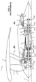
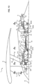
- THE figures 1 And 2 schematically represent an example of a double-body double-flow turbojet engine 1 with reduction gear.
- the turbojet 1 illustrated in these figures comprises a fan 2, a low pressure body 3, a high pressure body 4, a combustion chamber 5 and a gas exhaust nozzle 6.
- the high pressure body 4 comprises a high pressure compressor 41, a high pressure turbine 42 and a high pressure shaft 43 coupling the high pressure turbine 42 to the high pressure compressor 41.
- the low pressure body 3 includes a low pressure compressor 31, a low pressure turbine 32 and a low pressure shaft 33 coupling the low pressure turbine 32 to the low pressure compressor 31, and extending inside the high pressure shaft 43 .
- the high pressure turbine 42 rotates the high pressure compressor 41 via the high pressure shaft 43, while the low pressure turbine 32 rotates the low pressure compressor 31 and the fan 2 via the low pressure shaft 33.
- the turbojet 1 illustrated on the figures 1 And 2 is a turbofan engine with a high bypass ratio, the dilution rate being defined as the ratio between the flow rate of the secondary flow B (cold) and the flow rate of the primary flow A (hot) .
- the fan 2 is decoupled from the low pressure turbine 32, thus making it possible to independently optimize their respective rotation speeds.
- Decoupling is for example obtained using a reducer 7, such as an epicyclic gearing, arranged between the upstream end of the low pressure shaft 33 and the fan 2.
- the Blower 2 is driven by the low pressure shaft 33 via the reducer 7 and an additional shaft 23, called the fan shaft.
- This decoupling makes it possible to reduce the rotation speed and the pressure ratio of the fan (in English “fan pressure ratio”), and thus to increase the power extracted by the low pressure turbine. Thanks to the reduction gear, the low-pressure shaft can rotate at higher rotational speeds than in conventional turbojet engines.
- This arrangement makes it possible to improve the propulsion efficiency of the turbojet and reduce its fuel consumption, as well as the noise emitted by the fan.
- the fan shaft 23, the low pressure shaft 33 and the high pressure shaft 43 are guided in rotation relative to the structural parts of the turbojet 1 (these structural parts including in particular the inlet casing, the inter-compressor casing , the inter-turbine casing and the exhaust casing) through different bearings.
- each shaft is supported by a first bearing (or thrust bearing), capable of supporting both radial forces and axial forces exerted on the shaft, and by one or more additional bearing(s). s) capable of supporting only radial forces exerted on the shaft.
- first bearing or thrust bearing
- additional bearing(s) capable of supporting only radial forces exerted on the shaft.
- the fan shaft 23 is supported by a first fan bearing S#1 (upstream bearing) and a second fan bearing S#2 (downstream bearing) arranged between the fan shaft 23 and the inlet casing 8 .
- the second bearing S#2 is a “thrust” bearing, that is to say it is capable of supporting the axial forces exerted (upstream) by the fan 2 on the fan shaft 23 .
- the low pressure shaft 33 is supported by four bearings, including a first bearing BP#1, disposed between the low pressure shaft 33 and the inlet casing 8 (near the upstream end of the low pressure shaft) , a second bearing BP#2 disposed between the low pressure shaft 33 and the inter-compressor casing 9, a third bearing BP#3, disposed between the low pressure shaft 33 and the inter-turbine casing 10, and a fourth bearing BP#4, arranged between the low pressure shaft 33 and the exhaust casing 11.
- the first bearing BP#1 is a “thrust” bearing, that is to say it is capable of supporting the forces axial forces exerted (downstream) by the low pressure turbine 3 on the low pressure shaft 33.
- the high pressure shaft 43 is supported by three bearings, including a first HP#1 bearing, disposed between the high pressure shaft 43 and the inter-compressor casing 9 (near the upstream end of the high pressure shaft) , a second bearing HP#2 disposed between the high pressure shaft 43 and the inter-compressor casing 9, a third bearing HP#3, disposed between the high pressure shaft 43 and the inter-turbine casing 10.
- the first HP bearing #1 is also a “thrust” bearing, that is to say it is capable of supporting the axial forces exerted (downstream) by the high pressure turbine 41 on the high pressure shaft 43.
- the size of the first bearing BP#1 makes it difficult to integrate this bearing into the center of the low pressure compressor 31.
- the integration of the reducer 7 and the BP#1 bearing requires modifying the shape of the primary vein used to guide the primary flow A.
- WO2014197155A1 describes a twin-body turbojet engine in which the low pressure shaft is supported by a first thrust bearing disposed, upstream, between the low pressure shaft and the high pressure shaft, and a second bearing disposed, downstream, between the low pressure shaft and low pressure compressor housing.
- the document WO2017109330A1 describes a twin-spool turbojet engine in which the low pressure shaft is supported by a thrust bearing arranged, upstream, between the low pressure shaft and the inter-compressor casing, and two bearings arranged, downstream, between the shaft low pressure and the exhaust housing.
- An aim of the invention is to propose a twin-body turbojet having an arrangement which facilitates the integration of the low-pressure shaft thrust bearing within the turbojet.
- this goal is achieved in the context of the present invention thanks to a twin-body turbojet according to claim 1.
- the low pressure shaft thrust bearing may be located near the downstream end of the low pressure shaft, in the center of the exhaust housing, where more space is available.
- This arrangement can also allow the removal of one or more low pressure level(s) (for example the fourth level BP#4 on the figures 1 And 2 ).
- this arrangement makes it possible to reduce the relative axial movements between the rotor and the stator of the low pressure turbine due to the expansions of the different parts of the turbojet when it is in operation.
- the proposed arrangement makes it possible not to modify the shape of the primary vein.
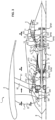
- the turbojet 1 shown comprises a fan 2, a low pressure body 3, a high pressure body 4, a combustion chamber 5 and a gas exhaust nozzle 6.
- the fan 2 comprises a fan disk 21 provided with fan blades 22 at its periphery which, when rotated, drive the air flow into the primary and secondary flow spaces of the turbojet 1.
- the low pressure body 3 comprises a low pressure compressor 31, a low pressure turbine 32 and a low pressure shaft 33 coupling the low pressure turbine 32 to the low pressure compressor 31.
- the high pressure body 4 comprises a high pressure compressor 41, a high pressure turbine 42 and a high pressure shaft 43 coupling the high pressure turbine 42 to the high pressure compressor 43.
- the low pressure shaft 33 extends inside the high pressure shaft 43.
- the low pressure shaft 33 and the high pressure shaft 43 are coaxial.
- the low pressure shaft 33 and the high pressure shaft 43 have the X axis as their axis of rotation, which is also the longitudinal axis of the turbojet 1.
- the high pressure turbine 42 rotates the high pressure compressor 41 via the high pressure shaft 43, while the low pressure turbine 32 rotates the low pressure compressor 31 and the fan 2 via the low pressure shaft 33.
- double body means that the turbojet comprises only two bodies (bodies 3 and 4), each body consisting of a compressor, a turbine and a shaft coupling the turbine to the compressor.
- a double-body turbojet engine is distinguished, for example, from a “triple-body” turbojet engine which includes a low-pressure body, a high-pressure body and an intermediate body interposed between the high-pressure body and the low-pressure body.
- the turbojet 1 further comprises a fan shaft 23 and a reduction gear 7, coupling the fan shaft 23 to the low pressure shaft 33.
- the fan disk 21 is fixedly mounted on the fan shaft 23 so that the fan disk 21 is rotated by the low pressure shaft 33 via the reducer 7 and the fan shaft 23.
- the low pressure compressor 31 comprises a low pressure compressor casing 311, a stator 312 and a rotor 313.
- the stator 312 comprises stator vanes 314 fixedly mounted on the casing 311.
- the rotor 313 comprises rotor vanes 315 adapted to be driven in rotation relative to the stator blades via the low pressure shaft 33.
- the rotor blades are fixedly mounted on the low pressure shaft 33.
- the rotor blades extend in the vein of circulation of the primary flow A by being interposed between the fixed vanes.
- the high pressure compressor 41 includes a high pressure compressor housing 411, a stator 412 and a rotor 413.
- the stator 412 includes stator vanes fixedly mounted on the housing 411.
- the rotor 413 includes rotor vanes of its own to be rotated relative to the stator vanes via the high pressure shaft 43.
- the rotor vanes are fixedly mounted on the high pressure shaft 43.
- the rotor vanes extend into the circulation vein of the primary flow A by being interposed between the fixed vanes.
- the low pressure turbine 32 comprises a low pressure turbine casing 321, a stator 322 and a rotor 323.
- the stator 322 comprises stator vanes fixedly mounted on the casing 321.
- the rotor 323 comprises rotor vanes adapted to be driven in rotation relative to the stator vanes by the exhaust gas flow.
- the rotor blades are fixedly mounted on the low pressure shaft 33. The rotor blades extend in the circulation vein of the primary flow A by being interposed between the fixed blades.
- the high pressure turbine 42 comprises a high pressure turbine casing 421, a stator 422 and a rotor 423.
- the stator 422 comprises stator vanes fixedly mounted on the casing 421.
- the rotor 423 comprises rotor vanes specific to be rotated relative to the stator vanes by the flow of exhaust gas.
- the rotor blades are fixedly mounted on the high pressure shaft 42. The rotor blades extend in the circulation vein of the primary flow A by being interposed between the fixed blades.
- the turbojet 1 comprises an inlet casing 8 (or intake casing) arranged around the fan 2.
- the inlet casing 8 comprises a rectifier 81 consisting of a series of fixed vanes 82, arranged in downstream of the blades 22 of the fan 2 and having the function of straightening the secondary flow B generated by the fan 2.
- the reducer 7 is fixed on the inlet casing 8.
- the turbojet 1 further comprises an inter-compressor casing 9 disposed between the low pressure compressor 31 and the high pressure compressor 41. More precisely, the inter-compressor casing 9 connects the casing 311 of the low pressure compressor 31 to the casing 411 of the high compressor pressure 41.
- the inter-compressor casing 9 is designed to support the axial forces transmitted by the inlet casing 8, these axial forces being generated by the fan 2 on the fan shaft 23.
- the inter-compressor casing 9 transmits these axial forces to the suspensions (not shown) by means of thrust recovery rods connecting the inter-compressor casing 9 to the suspensions.
- the turbojet 1 further comprises an inter-turbine casing 10 disposed between the high pressure turbine 42 and the low pressure turbine 32. More precisely, the inter-turbine casing 10 connects the casing 421 of the high pressure turbine 42 to the casing 321 of the low pressure turbine 32.
- the turbojet 1 further comprises an exhaust casing 11 and an exhaust nozzle 6 fixed to the exhaust casing 11.
- the exhaust nozzle 6 delimits a passage 62 for exhaust gases flowing downstream of the low pressure turbine 32.
- the exhaust casing 11 is fixed to the casing 321 of the low pressure turbine 32.
- the air flow sucked in by the blower 2 is divided into a primary flow A and a secondary flow B.
- the secondary flow B successively passes through the blower 2 and the rectifier 81.
- the primary flow A successively passes through the low pressure compressor 31 and the high pressure compressor 41.
- the pressurized air is injected into the combustion chamber 5 where it is used as an oxidizer for the combustion of the fuel.
- the flow of exhaust gas produced by combustion reaction flows successively through the high pressure turbine 42, the low pressure turbine 32 and escapes from the turbojet 1 via the exhaust nozzle 6.
- the flow of exhaust gas rotates the rotor 422 of the high pressure turbine 42 and the rotor 322 of the low pressure turbine 32.
- the rotor 422 of the high pressure turbine 42 in turn drives the rotor 412 of the high pressure compressor 41 by means of the high pressure shaft 43, while the rotor 322 of the low pressure turbine 32 drives the rotor 312 of the low pressure compressor 31 by means of the low pressure shaft 33.
- the rotor 322 of the low pressure turbine 32 also drives the fan disk 21 via the reducer 7 and the fan shaft 23.
- the fan shaft 23 is supported by a first fan shaft bearing S#1 (upstream bearing) and a second fan shaft bearing S#2 (downstream bearing), each bearing being disposed between the shaft fan 23 and the inlet casing 8.
- the second bearing S#2 is a “thrust” bearing, that is to say it is capable of transmitting the axial forces exerted to the inlet casing 8 ( upstream) by fan 2 on fan shaft 23.
- the low pressure shaft 33 is supported by three bearings BP#1, BP#2, BP#3.
- the first bearing BP#1 is arranged between the low pressure shaft 33 and the exhaust casing 11 (near the downstream end of the low pressure shaft 33).
- the first bearing BP#1 is a “thrust” bearing, that is to say it is capable of transmitting the axial forces exerted (downstream) on the low pressure shaft 33 to the exhaust casing 11.
- the thrust bearing BP#1 is capable of supporting both radial forces and axial forces exerted on the low pressure shaft 33.
- the thrust bearing BP#1 can be made up of a roller bearing. balls or a combination of several adjacent angular contact ball or tapered roller bearings arranged in opposition in an O or X configuration.
- the thrust bearing BP#1 comprises an inner ring 351 fixed on the low pressure shaft 33, an outer ring 352 fixed on the exhaust casing 11 and balls 353 or conical rollers arranged between the inner ring 352 and the outer ring 352.
- the second bearing BP#2 is arranged between the low pressure shaft 33 and the inter-compressor casing 9.
- the BP#2 bearing comprises an inner ring fixed on the low pressure shaft 33, an outer ring fixed on the inter-compressor casing 9 and rollers arranged between the inner ring and the outer ring.
- the third bearing BP#3 is arranged between the low pressure shaft 33 and the inter-turbine casing 10.
- the BP#3 bearing comprises an inner ring fixed on the low pressure shaft 33, an outer ring fixed on the inter-turbine casing 10 and rollers arranged between the inner ring and the outer ring.
- Each of the upstream bearings BP#2 and BP#3 is capable of supporting radial forces exerted on the low pressure shaft 33 while allowing a certain axial movement of the low pressure shaft 33 relative to the inter-compressor casing 9 and to the inter-turbine casing 10. This means that the bearings BP#2 and BP#3 do not transmit any axial force exerted on the low pressure shaft 33 to the casings.
- the low pressure shaft 33 undergoes an axial movement relative to the inter-compressor casing 9 and the inter-turbine casing 10 due to the expansion of certain parts of the turbojet 1, in particular of the high pressure compressor 41, the combustion chamber 5, the high pressure turbine 42 and the low pressure turbine 32.
- each BP#2 and BP#3 bearing are thus designed to be able to authorize such axial movement.
- each BP#2 and BP#3 bearing can be made up of a roller bearing.
- the first level BP#1 replaces the fourth level BP#4 of the figures 1 And 2 , so that only three bearings are necessary.
- the high pressure shaft 43 is also supported by three bearings HP#1, HP#2, HP#3.
- the first bearing HP#1 is arranged between the high pressure shaft 43 and the inter-compressor casing 9 (near the upstream end of the high pressure shaft 43).
- the first bearing HP#1 is a “thrust” bearing, that is to say it is capable of transmitting the axial forces exerted (downstream) on the high pressure shaft to the inter-compressor casing 9 .
- the thrust bearing HP#1 is capable of supporting both radial forces and axial forces exerted on the low pressure shaft 43.
- the second bearing HP#2 is also arranged between the high pressure shaft 43 and the inter-compressor casing 9, downstream of the first bearing HP#1.
- the third bearing HP#3 is placed between the high pressure shaft 43 and the inter-turbine casing 10.
- each of the HP#2 and HP#3 bearings is capable of supporting radial forces exerted on the high pressure shaft 43 while allowing a certain axial movement of the shaft high pressure 43 relative to the inter-compressor casing 9 and the inter-turbine casing 10. This means that the HP#2 and HP#3 bearings do not transmit any axial force exerted on the high pressure shaft 43.
- the arrangement of the BP#1 bearing in the center of the exhaust casing 11 has the effect of preventing any relative axial movement between the downstream end of the low pressure shaft 33 and the exhaust casing 11.
- This arrangement advantageously makes it possible to avoid or limit the axial movement of the rotor blades relative to the stator blades of the low pressure turbine 32, during the operation of the turbojet 1.
- this arrangement simplifies the design of the dynamic sealing devices (generally consisting of wipers and facing coverings of abradable material) necessary to prevent gas leaks between the rotor blades and the internal surface of the casing 321 of the low pressure turbine 32. In fact, only leaks due to radial movements must be prevented, axial movements being eliminated.
- the blades 315 of the rotor 313 are positioned relative to the blades 314 of the stator 312 so as to allow axial movement (parallel to the axis X) of the blades 315 of the rotor 313, towards the downstream of the turbojet 1 in the direction d air flow, in a displacement range of between 1 millimeter and 2 centimeters, preferably between 2 millimeters and 1 centimeter.
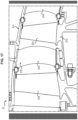
- the internal surface 316 of the low pressure compressor casing 311 has, between the fixed vanes 314, surface portions 317 of cylindrical shape of revolution, having the axis X of rotation of the low pressure shaft as axis of revolution.
- Each surface portion 317 allows the axial movement of a rotor blade 315 relative to the low pressure compressor casing 311.
- the internal surface 316 of the low pressure compressor casing 311 may present, at the location where the vanes 314 of the stator are fixed, portions of surface 318 which are non-cylindrical of revolution.
- the entire internal surface 316 of the low pressure compressor casing 311 has a cylindrical shape of revolution, having the axis X of rotation of the low pressure shaft as its axis of revolution.
- the internal surface 316 also allows the axial movement of the rotor blades 314 relative to the low pressure compressor casing 311.
- coatings 319 of abradable material are provided on the internal surface 316 of the low pressure compressor casing 311, facing the free end edges of the rotor blades 315.
- Each coating 319 of abradable material is dimensioned to be able to be hollowed out by the end edge of the blade 315 located opposite, during axial movement thereof.
- each stator blade 314 is provided with a heel 343 1 formed of abradable material fixed to the free end edge of the blade, and the rotor 313 is provided with lip 342 arranged opposite the heel 341.
- Each heel 341 made of abradable material is dimensioned to be able to be hollowed out by the lips 342, during axial movement of the rotor 313 relative to the stator 312.
- the low pressure shaft 33 is coupled with the input shaft of the reducer via a coupling authorizing a translation of the low pressure shaft 33 relative to the input shaft of the reducer 7.
- One solution consists in particular of providing the upstream end of the low pressure shaft 33 and the end of the input shaft of the reducer 7 with longitudinal splines, the splines of the input shaft of the reducer 7 cooperating with the splines of the low pressure shaft 33 so as to make the two shafts integral in rotation while allowing translation of one relative to the other.
- the splines may be ball splines.
- the reduction gear 7 can comprise an epicyclic gear designed to allow movement of its internal sun gear or its external sun gear relative to the satellites, for example using straight teeth.
- the radius D2 of the first bearing BP#1 is defined as the distance between the longitudinal axis X of the turbojet 1 and the center of a ball 353 of the bearing 350 ball bearing.
- Rays D1 and D2 verify the following condition: D2 > 0.70 x D1, and preferably D2> 0.75 x D1.
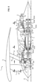
- THE figures 5 And 6 schematically represent a twin-body turbojet conforming to a second embodiment of the invention.
- the turbojet 1 does not include a third BP#3 bearing disposed between the low pressure shaft 33 and the inter-turbine casing 10.
- the turbojet includes a fourth bearing BP#4 disposed between the low pressure shaft 33 and the exhaust casing 11, upstream of the BP#1 bearing.
- the BP#4 bearing comprises an inner ring fixed on the low pressure shaft 33, an outer ring fixed on the exhaust casing 11 and rollers arranged between the inner ring and the outer ring.
- the BP#4 bearing is capable of supporting radial forces exerted on the low pressure shaft 33 while allowing a certain axial movement of the low pressure shaft 33 relative to the exhaust casing 11. This means that the bearing BP#4 does not transmit any axial force exerted on the low pressure shaft 33 to the casings.
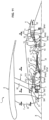
- THE figures 7 And 8 schematically represent a twin-body turbojet according to a third embodiment of the invention.
- This third embodiment is identical to the second embodiment, with the exception of the following characteristics:
- the fourth bearing BP#4 is arranged between the low pressure shaft 33 and the exhaust casing 11, downstream of the bearing BP#1.
- THE figures 9 And 10 schematically represent a twin-body turbojet according to a fourth embodiment of the invention.
- the turbojet 1 comprises a third bearing BP#3 disposed between the low pressure shaft 33 and the inlet casing 8 (near the upstream end of the low pressure shaft).
- the BP#3 bearing is capable of supporting radial forces exerted on the low pressure shaft 33 while allowing a certain axial movement of the low pressure shaft 33 relative to the inlet casing 8. This means that the bearing BP#3 does not transmit any axial force exerted on the low pressure shaft 33 to the casings.
- the turbojet 1 thus comprises four bearings BP#1 to BP#4 supporting the low pressure shaft 33: a first bearing BP#1 disposed between the low pressure shaft 33 and the exhaust casing 11 , a second bearing BP#2 disposed between the low pressure shaft 33 and the inter-compressor casing 9, a third bearing BP#3, disposed between the low pressure shaft 33 and the inlet casing 8 (near the upstream end of the low pressure shaft), and a fourth bearing BP#4, disposed between the low pressure shaft 33 and the exhaust casing 11, downstream of the first bearing BP#1.
- Only the first bearing BP#1 is a “thrust” bearing, that is to say it is capable of supporting the axial forces exerted (downstream) by the low pressure turbine 3 on the lower shaft pressure 33.
- THE figures 11 And 12 schematically represent a twin-body turbojet according to a fifth embodiment of the invention.
- the turbojet 1 comprises a fourth bearing BP#4 disposed between the low pressure shaft 33 and the inlet casing 8 (near the upstream end of the low pressure shaft), upstream of the second bearing BP#2.
- the turbojet 1 thus comprises four bearings BP#1 to BP#4 supporting the low pressure shaft 33: a first bearing BP#1 disposed between the low pressure shaft 33 and the exhaust casing 11 , a second bearing BP#2 disposed between the low pressure shaft 33 and the inter-compressor casing 9, a third bearing BP#3, disposed between the low pressure shaft 33 and the inter-turbine casing 10, upstream of the first bearing BP#1, and a fourth bearing BP#4, placed between the low pressure shaft 33 and the inlet casing 8 (near the upstream end of the low pressure shaft).
- Only the first bearing BP#1 is a “thrust” bearing, that is to say it is capable of supporting the axial forces exerted (downstream) by the low pressure turbine 3 on the lower shaft pressure 33.
- THE figures 13 And 14 schematically represent a twin-body turbojet according to a sixth embodiment of the invention.
- the turbojet 1 does not include a third BP#3 bearing disposed between the low pressure shaft 33 and the inter-turbine casing 10.
- the turbojet 1 thus comprises three bearings BP#1, BP#2 and BP#4 supporting the low pressure shaft 33: a first bearing BP#1 disposed between the low pressure shaft 33 and the casing exhaust 11, a second bearing BP#2 disposed between the low pressure shaft 33 and the inter-compressor casing 9, and a fourth bearing BP#4, disposed between the low pressure shaft 33 and the inlet casing 8 (near the upstream end of the low pressure shaft).
- Only the first bearing BP#1 is a “thrust” bearing, that is to say it is capable of supporting the axial forces exerted (downstream) by the low pressure turbine 3 on the lower shaft pressure 33.
- THE figures 15 And 16 schematically represent a twin-body turbojet conforming to a seventh embodiment of the invention.
- the turbojet 1 does not include a fourth BP#4 bearing disposed between the low pressure shaft 33 and the inlet casing 8.
- the turbojet 1 thus comprises two bearings BP#1 and BP#2 supporting the low pressure shaft 33: the first bearing BP#1 disposed between the low pressure shaft 33 and the exhaust casing 11 and the second bearing BP#2 disposed between the low pressure shaft 33 and the inter-compressor casing 9.
- the first bearing BP#1 is a “thrust” bearing, that is to say it is capable of supporting the axial forces exerted (downstream) by the low pressure turbine 3 on the low pressure shaft 33.
- the second bearing BP#2 is capable of supporting radial forces exerted on the low pressure shaft 33 while allowing a certain axial movement of the low pressure shaft 33 relative to the inter-compressor casing 9. This means that the BP#2 bearing does not transmit any axial force exerted on the low pressure shaft 33 to the casings.
- FIG. 21 schematically represents a twin-body turbojet according to an eighth embodiment of the invention.
- the low pressure shaft 33 is formed in two parts.
- the low pressure shaft 33 in fact comprises an upstream part of the low pressure shaft 331, a downstream part of the low pressure shaft 332 and a coupling assembly 333 connecting the downstream part of the low pressure shaft 332 and the upstream part of low pressure shaft 331 between them.
- the coupling assembly 333 can be positioned near the upstream end of the low pressure shaft 33 (position referenced 333-a on the Figure 21 ) or near the downstream end of the low pressure shaft 33 (position referenced 333-b on the Figure 21 ).
- the coupling assembly is adapted to transmit a torque between the low pressure shaft downstream part 332 and the low pressure shaft upstream part 331, while allowing relative axial movement between the low pressure shaft downstream part 332 and the upstream part of the low pressure shaft 331 due to the expansion of certain parts of the turbojet 1.
- the low pressure shaft 33 is supported by four bearings, including a first bearing BP#1, a second bearing BP#2, a third bearing BP#3 and a fourth bearing BP#4.
- the first bearing BP#1 is arranged between the downstream part of the low pressure shaft 332 and the exhaust casing 11.
- the first bearing BP#1 is a “thrust” bearing, that is to say that it is capable of transmitting the axial forces exerted on the upstream part of the low pressure shaft 331.
- the thrust bearing BP#1 comprises an inner ring fixed on the downstream part of the low pressure shaft 332, an outer ring fixed on the exhaust casing 11 and balls or conical rollers arranged between the ring inner and outer ring.
- the fourth bearing BP#4 is arranged between the upstream part of the low pressure shaft 331 and the inlet casing 8.
- the fourth bearing BP#4 is also a “thrust” bearing, i.e. it is capable of withstanding axial forces.
- the thrust bearing BP#4 comprises an inner ring fixed on the upstream part of the low pressure shaft 331, an outer ring fixed on the inlet casing 8 and balls or conical rollers arranged between the ring inner and outer ring.
- the bearing BP#4 prevents any relative axial movement between the upstream end of the low pressure shaft 33 and the inlet casing 8, while the bearing BP#1 prevents any relative axial movement between the the downstream end of the low pressure shaft 33 and the exhaust casing 11.
- the coupling assembly 333 allows relative axial movement between the downstream part of the low pressure shaft 332 and the upstream part of the low pressure shaft 331.
- the second bearing BP#2 can be placed between the low pressure shaft 33 and the inter-compressor casing 9.
- the third bearing BP#3 is arranged between the low pressure shaft 33 and the exhaust casing 11.
- the second bearing BP#2 and the third bearing BP#3 are capable of supporting radial forces exerted on the low pressure shaft 33 while allowing a certain axial movement of the low pressure shaft 33 relative to the inter-casing. compressor 9 and to the exhaust casing. This means that the bearings BP#2 and BP#3 do not transmit any axial force exerted on the low pressure shaft 33 to the casings.
- the coupling assembly 333 is positioned near the upstream end of the low pressure shaft 33 (in this position, the coupling assembly is referenced 333-a on the Figure 21 ). In this case, the coupling assembly 333 is arranged downstream of the junction between the low pressure shaft 33 and the rotor 313 of the low pressure compressor 31.
- the coupling assembly 333 is positioned near the downstream end of the low pressure shaft 33 (in this position, the coupling assembly is referenced 333-b). In this case, the coupling assembly 333 is arranged upstream of the junction between the low pressure shaft 33 and the rotor 323 of the low pressure turbine 32.
- the BP#4 bearing can be dimensioned so as to have a smaller footprint than the BP#1 bearing of a conventional twin-body turbojet as shown in the figures. figures 1 And 2 .
- the BP#4 bearing may have a reduced external diameter and/or balls having a reduced diameter.
- the recovery of the axial forces exerted on the low pressure shaft 33 is distributed between the bearing BP#1 and the bearing BP#4.
- the BP#4 bearing does not take up the axial forces exerted on the low pressure shaft 33 by the low pressure turbine 32.
- the fourth bearing BP#4 can be arranged in the center of the low pressure compressor 31.
- the low pressure compressor 31 can include rotor disks 343 having a reduced bore radius. It is thus possible to optimize the shape of the discs to reduce their weight and/or reduce the internal diameter of the compressor vein.
- the turbojet 1 comprises a conventional low pressure compressor casing such as that shown in the figure. Figure 17 .
- the BP#4 bearing prevents any axial movement (parallel to the axis .
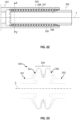
- FIG. 22 schematically represents a first example of a coupling assembly 333 allowing the downstream part of the low pressure shaft 331 and the upstream part of the low pressure shaft 332 to be connected together.
- the upstream part of the low pressure shaft 331 comprises an internal surface 335 and the downstream part of the low pressure shaft 332 comprises an external surface 336.
- the internal surface 335 may have a cylindrical shape of revolution having the axis X for axis of revolution.
- the external surface 336 may have a cylindrical shape of revolution having the axis X as its axis of revolution.
- the internal surface 335 surrounds the external surface 336.
- the internal surface 335 has first axial grooves.
- the external surface 336 has second axial grooves extending opposite the first axial grooves.
- the coupling assembly 333 further comprises a plurality of rolling elements 337 (for example balls) interposed between the internal surface 335 and the external surface 336.
- Each rolling element 337 extends both in one of the first grooves and in one of the second grooves.
- the rolling elements 337 are capable of transmitting a torque between the downstream part of the low pressure shaft 332 and the upstream part of the low pressure shaft 331, while allowing axial movement of one relative to the other parallel to the X axis.
- the coupling assembly 333 includes a cage 338 disposed between the inner surface 335 and the outer surface 336.
- the cage 338 includes a plurality of openings, each opening receiving one of the rolling elements 337 to maintain the rolling elements 337 spaced apart one another.
- the coupling assembly may be a coupling assembly conforming to that described in the patent application FR n°1854044 filed on May 15, 2018 filed in the name of Safran Aircraft Engines, which is incorporated herein by reference.
- FIG. 23 schematically represents a second example of coupling assembly 333.
- the coupling assembly 333 comprises a bellows junction portion 339.
- the bellows junction portion 339 connects the upstream part of the low pressure shaft 331 to the downstream part of the low pressure shaft 332.
- the portion bellows junction 339 comprises a plurality of bellows capable of deforming to allow relative axial movement between the upstream part of low pressure shaft 331 and the downstream part of low pressure shaft 332 parallel to the axis a relative rotation between the upstream part of the low pressure shaft 331 and the downstream part of the low pressure shaft 332 around the axis X.
- the bellows junction portion 339 comprises a first bellows 341 and a second bellows 342.
- the bellows junction portion 339 has been shown in solid lines in a first position (or retracted position) and in dotted lines in a second position (or stretched position.
Landscapes
- Engineering & Computer Science (AREA)
- Chemical & Material Sciences (AREA)
- Combustion & Propulsion (AREA)
- Mechanical Engineering (AREA)
- General Engineering & Computer Science (AREA)
- Structures Of Non-Positive Displacement Pumps (AREA)
Claims (9)
- Zweiwellen-Mantelstrom-Triebwerk (1), das umfasst:- einen Niederdruckmantel (3), der einen Niederdruckverdichter (31), eine Niederdruckturbine (32) und eine Niederdruckwelle (33) umfasst, die die Niederdruckturbine (32) mit dem Niederdruckverdichter (31) verbindet;- einen Hochdruckmantel (4), der einen Hochdruckverdichter (41), eine Hochdruckturbine (42) und eine Hochdruckwelle (43) umfasst, die die Hochdruckturbine (42) mit dem Hochdruckverdichter (41) verbindet, wobei die Niederdruckwelle (33) sich im Inneren der Hochdruckwelle (43) erstreckt,- eine Gebläsewelle (23),- einen Untersetzungsmechanismus (7), der die Niederdruckwelle (33) und die Gebläsewelle (23) koppelt,- ein Abgasgehäuse (11), durch das Abgase stromabwärtig der Niederdruckturbine (32) ausströmen,wobei das Triebwerk (1) dadurch gekennzeichnet ist, dass es ferner ein Niederdruckwellen-Schublager (BP#1) umfasst, das einen inneren Ring und einen äußeren Ring umfasst, wobei der eine von den Ringen an der Niederdruckwelle (33) befestigt ist und der andere von den Ringen an dem Abgasgehäuse (11) befestigt ist, und dadurch, dassder Niederdruckverdichter (31) umfasst:- ein Niederdruck-Verdichtergehäuse (311), das eine Innenoberfläche (316) aufweist, die einen Zirkulationsgang einer Luftströmung (A) durch den Niederdruckverdichter (31) abgrenzt,- einen Stator (312), der Schaufeln (314) umfasst, die in Bezug auf das Niederdruck-Verdichtergehäuse (311) fest montiert sind und sich in dem Zirkulationsgang der Luftströmung erstrecken, und- einen Rotor (313), der bewegliche Schaufeln (315) umfasst, die geeignet sind, durch die Niederdruckwelle (33) in Bezug auf den Stator (312) drehbar angetrieben zu werden, wobei die beweglichen Schaufeln (315) sich in dem Zirkulationsgang der Luftströmung erstrecken und dabei zwischen den festen Schaufeln (314) eingeschoben sind,wobei die Innenoberfläche (316) des Niederdruck-Vedichtergehäuses (311), die festen Schaufeln (314) und die beweglichen Schaufeln (315) derart in Bezug aufeinander angeordnet sind, dass eine axiale Verlagerung der beweglichen Schaufeln (315) in Bezug auf die festen Schaufeln (314) parallel zur Drehachse (X) der Niederdruckwelle (33) zugelassen wird undwobei die Innenoberfläche (316) des Niederdruck-Verdichtergehäuses (311) zwischen den festen Schaufeln (314) Abschnitte (317) mit zylindrischer Umlaufform aufweist, die die Drehachse (X) der Niederdruckwelle (33) als Umlaufachse aufweisen.
- Triebwerk nach Anspruch 1, das ferner höchstens zwei zusätzliche Niederdruckwellenlager (BP#2, BP#3) umfasst, wobei jedes zusätzliche Niederdruckwellenlager (BP#2, BP#3) einen inneren Ring und einen äußeren Ring umfasst, wobei der eine von den Ringen an der Niederdruckwelle (33) befestigt ist und der andere von den Ringen an einem Gehäuse (9, 10) des Triebwerks (1) befestigt ist.
- Triebwerk nach einem der Ansprüche 1 und 2, das ferner ein einziges zusätzliches Niederdruckwellenlager (BP#2) umfasst, wobei das zusätzliche Niederdruckwellenlager (BP#2) einen inneren Ring und einen äußeren Ring umfasst, wobei der eine von den Ringen an der Niederdruckwelle (33) befestigt ist und der andere von den Ringen an einem Gehäuse (9) der Turbomaschine (1) befestigt ist.
- Triebwerk nach einem der Ansprüche 2 und 3, wobei jedes zusätzliche Niederdruckwellen-Schublager (BP#2, BP#3) einen inneren Ring oder einen äußeren Ring umfasst, der an einem Zwischenverdichtergehäuse (9) oder einem Zwischenturbinengehäuse (10) des Triebwerks befestigt ist.
- Triebwerk nach einem der Ansprüche 1 bis 4, wobei die zugelassene axiale Verlagerung zwischen 1 Millimeter und 2 Zentimeter, vorzugsweise zwischen 2 Millimeter und 1 Zentimeter beträgt.
- Triebwerk nach einem der Ansprüche 1 bis 5, wobei die Innenoberfläche (316) des Niederdruck-Verdichtergehäuses (311) eine zylindrische Umlaufform aufweist, die die Drehachse (X) der Niederdruckwelle (33) als Umlaufachse aufweist.
- Triebwerk nach einem der Ansprüche 1 bis 6, wobei die Niederdruckwelle (33) ein stromaufwärtiges Ende aufweist, das mit Rillen versehen ist, und der Untersetzungsmechanismus (7) eine Eingangswelle umfasst, die ein mit Rillen versehenes Ende aufweist, wobei die Rillen der Eingangswelle des Untersetzungsmechanismus (7) derart mit den Rillen der Niederdruckwelle (33) zusammenwirken, dass die zwei Wellen drehfest werden und dabei eine translatorische Bewegung der einen Welle in Bezug auf die andere zugelassen wird.
- Triebwerk nach einem der Ansprüche 1 bis 7, wobei der Niederdruckverdichter (31) eine stromaufwärtige Niederdruck-Verdichterscheibe (343) umfasst, die eine Bohrung aufweist, die einen ersten Radius (D1) aufweist, und wobei das erste Niederdruckwellen-Schublager (BP#1) einen zweiten Radius (D2) aufweist, derart dass: D2 > 0,70 × D1, vorzugsweise D2 > 0,75 × D1, wobei D1 der erste Radius ist und D2 der zweite Radius ist.
- Zweiwellen-Mantelstrom-Triebwerk (1), das umfasst:- einen Niederdruckmantel (3), der einen Niederdruckverdichter (31), eine Niederdruckturbine (32) und eine Niederdruckwelle (33) umfasst, die die Niederdruckturbine (32) mit dem Niederdruckverdichter (31) verbindet;- einen Hochdruckmantel (4), der einen Hochdruckverdichter (41), eine Hochdruckturbine (42) und eine Hochdruckwelle (43) umfasst, die die Hochdruckturbine (42) mit dem Hochdruckverdichter (41) verbindet, wobei die Niederdruckwelle (33) sich im Inneren der Hochdruckwelle (43) erstreckt,- eine Gebläsewelle (23),- einen Untersetzungsmechanismus (7), der die Niederdruckwelle (33) und die Gebläsewelle (23) koppelt,- ein Abgasgehäuse (11), durch das Abgase stromabwärtig der Niederdruckturbine (32) ausströmen,wobei das Triebwerk (1) dadurch gekennzeichnet ist, dass es ferner ein erstes Niederdruckwellen-Schublager (BP#1), das einen inneren Ring und einen äußeren Ring umfasst, wobei der eine von den Ringen an der Niederdruckwelle (33) befestigt ist und der andere von den Ringen an dem Abgasgehäuse (11) befestigt ist, und ein zweites Niederdruckwellen-Schublager (BP#4) umfasst, das einen inneren Ring und einen äußeren Ring umfasst, wobei der eine von den Ringen an der Niederdruckwelle (33) befestigt ist und der andere von den Ringen am Eingangsgehäuse (8) befestigt ist,und dadurch, dass die Niederdruckwelle (33) einen stromaufwärtigen Niederdruckwellenteil (331), einen stromabwärtigen Niederdruckwellenteil (332) und eine Kopplungsbaugruppe (333) umfasst, die dazu geeignet ist, ein Drehmoment zwischen dem stromaufwärtigen Niederdruckwellenteil (331) und dem stromabwärtigen Niederdruckwellenteil (332) zu übertragen und dabei eine relative axiale Verlagerung zwischen dem stromaufwärtigen Niederdruckwellenteil (331) und dem stromabwärtigen Niederdruckwellenteil (332) zuzulassen.
Applications Claiming Priority (2)
| Application Number | Priority Date | Filing Date | Title |
|---|---|---|---|
| FR1757881A FR3070419B1 (fr) | 2017-08-25 | 2017-08-25 | Turboreacteur a double corps ayant un palier de butee d'arbre basse pression positionne dans le carter d'echappement |
| PCT/FR2018/052101 WO2019038510A1 (fr) | 2017-08-25 | 2018-08-24 | Turboreacteur a double corps ayant un palier de butee d'arbre basse pression positionne dans le carter d'echappement |
Publications (3)
| Publication Number | Publication Date |
|---|---|
| EP3673164A1 EP3673164A1 (de) | 2020-07-01 |
| EP3673164B1 EP3673164B1 (de) | 2021-04-14 |
| EP3673164B2 true EP3673164B2 (de) | 2024-04-03 |
Family
ID=59859378
Family Applications (1)
| Application Number | Title | Priority Date | Filing Date |
|---|---|---|---|
| EP18769757.8A Active EP3673164B2 (de) | 2017-08-25 | 2018-08-24 | Zweiwellen-mantelstrom-triebwerk mit einem niederdruckwellenschublager im abgasgehäuse |
Country Status (5)
| Country | Link |
|---|---|
| US (1) | US20200191055A1 (de) |
| EP (1) | EP3673164B2 (de) |
| CN (1) | CN111094722B (de) |
| FR (1) | FR3070419B1 (de) |
| WO (1) | WO2019038510A1 (de) |
Families Citing this family (6)
| Publication number | Priority date | Publication date | Assignee | Title |
|---|---|---|---|---|
| FR3086343B1 (fr) * | 2018-09-24 | 2020-09-04 | Safran Aircraft Engines | Turbomachine a reducteur pour un aeronef |
| GB201913195D0 (en) * | 2019-09-12 | 2019-10-30 | Rolls Royce Plc | Gas turbine engine |
| FR3115827B1 (fr) * | 2020-11-05 | 2023-09-22 | Safran Nacelles | Fixation d’un cône d’éjection dans une tuyère de turbomachine |
| US20230121939A1 (en) | 2021-10-19 | 2023-04-20 | Raytheon Technologies Corporation | Straddle mounted low pressure compressor |
| FR3144200A1 (fr) * | 2022-12-22 | 2024-06-28 | Safran Aircraft Engines | Maîtrise du comportement dynamique d’un système propulsif aéronautique |
| FR3144189A1 (fr) * | 2022-12-22 | 2024-06-28 | Safran Aircraft Engines | Amélioration du comportement dynamique de l’arbre d’entrainement d’une soufflante d’un système propulsif aéronautique |
Family Cites Families (24)
| Publication number | Priority date | Publication date | Assignee | Title |
|---|---|---|---|---|
| US2747367A (en) * | 1950-03-21 | 1956-05-29 | United Aircraft Corp | Gas turbine power plant supporting structure |
| GB1113542A (en) | 1967-01-06 | 1968-05-15 | Rolls Royce | Gas turbine engine |
| GB1501916A (en) * | 1975-06-20 | 1978-02-22 | Rolls Royce | Matching thermal expansions of components of turbo-machines |
| FR2722836B1 (fr) * | 1994-07-20 | 1996-08-30 | Snecma | Turbomachine munie de moyens d'ajustement du jeu radial entre rotor e stator |
| DE102005048982A1 (de) | 2005-10-13 | 2007-04-19 | Mtu Aero Engines Gmbh | Vorrichtung und Verfahren zum axialen Verschieben eines Turbinenrotors |
| US9938898B2 (en) | 2011-07-29 | 2018-04-10 | United Technologies Corporation | Geared turbofan bearing arrangement |
| EP2592235A3 (de) * | 2011-11-11 | 2014-10-15 | United Technologies Corporation | Verdichteranordnungen für einen Gasturbinenmotor |
| US8402741B1 (en) | 2012-01-31 | 2013-03-26 | United Technologies Corporation | Gas turbine engine shaft bearing configuration |
| US9476320B2 (en) * | 2012-01-31 | 2016-10-25 | United Technologies Corporation | Gas turbine engine aft bearing arrangement |
| US20150192070A1 (en) | 2012-01-31 | 2015-07-09 | United Technologies Corporation | Geared turbofan gas turbine engine architecture |
| US9297422B2 (en) * | 2012-10-25 | 2016-03-29 | Pratt & Whitney Canada Corp. | Coupling element for torque transmission in a gas turbine engine |
| EP3004595B1 (de) * | 2013-06-03 | 2020-09-02 | United Technologies Corporation | Anordnung aus einem turbofan-triebwerklager und einem getriebe |
| FR3007458B1 (fr) * | 2013-06-21 | 2017-11-10 | Snecma | Carter intermediaire ameliore de turbomachine et ensemble d'entrainement de boitier d'accessoire |
| US9551353B2 (en) * | 2013-08-09 | 2017-01-24 | General Electric Company | Compressor blade mounting arrangement |
| US20160195010A1 (en) * | 2014-07-15 | 2016-07-07 | United Technologies Corporation | Vaneless counterrotating turbine |
| US10119592B2 (en) * | 2015-03-06 | 2018-11-06 | Elwha Llc | Vehicle drivetrain with active magnetic bearings |
| US9932858B2 (en) * | 2015-07-27 | 2018-04-03 | General Electric Company | Gas turbine engine frame assembly |
| US10196986B2 (en) * | 2015-09-04 | 2019-02-05 | General Electric Company | Hydrodynamic seals in bearing compartments of gas turbine engines |
| US10094283B2 (en) * | 2015-10-28 | 2018-10-09 | General Electric Company | Differential gas bearing for aircraft engines |
| FR3046202B1 (fr) * | 2015-12-24 | 2017-12-29 | Snecma | Turboreacteur avec un moyen de reprise de poussee sur le carter inter-compresseurs |
| US10590854B2 (en) * | 2016-01-26 | 2020-03-17 | United Technologies Corporation | Geared gas turbine engine |
| US10717539B2 (en) * | 2016-05-05 | 2020-07-21 | Pratt & Whitney Canada Corp. | Hybrid gas-electric turbine engine |
| US10883424B2 (en) * | 2016-07-19 | 2021-01-05 | Pratt & Whitney Canada Corp. | Multi-spool gas turbine engine architecture |
| BE1024941B1 (fr) * | 2017-01-26 | 2018-08-28 | Safran Aero Boosters S.A. | Controle actif de jeu pour compresseur de turbomachine |
-
2017
- 2017-08-25 FR FR1757881A patent/FR3070419B1/fr active Active
-
2018
- 2018-08-24 US US16/641,337 patent/US20200191055A1/en not_active Abandoned
- 2018-08-24 CN CN201880059737.7A patent/CN111094722B/zh active Active
- 2018-08-24 WO PCT/FR2018/052101 patent/WO2019038510A1/fr not_active Ceased
- 2018-08-24 EP EP18769757.8A patent/EP3673164B2/de active Active
Also Published As
| Publication number | Publication date |
|---|---|
| FR3070419A1 (fr) | 2019-03-01 |
| WO2019038510A1 (fr) | 2019-02-28 |
| EP3673164A1 (de) | 2020-07-01 |
| CN111094722B (zh) | 2021-02-23 |
| US20200191055A1 (en) | 2020-06-18 |
| CN111094722A (zh) | 2020-05-01 |
| FR3070419B1 (fr) | 2019-08-23 |
| EP3673164B1 (de) | 2021-04-14 |
Similar Documents
| Publication | Publication Date | Title |
|---|---|---|
| EP3673164B1 (de) | Zweiwellen-mantelstrom-triebwerk mit einem niederdruckwellenschublager im abgasgehäuse | |
| EP2419616B1 (de) | Zwei-wellen-gasturbinen triebwerk mit zwischenwellenlager | |
| FR3066559B1 (fr) | Module de soufflante a pales a calage variable | |
| EP3864297B1 (de) | Lüftermodul mit schaufeln mit variabler neigung | |
| EP2867551B1 (de) | Lager mit schmiermittel und anordnung zum ändern der schaufelsteigung eines turboantriebswerks eines mit diesem lager ausgestatteten flugzeuges | |
| FR2872870A1 (fr) | Commande de jeu de pale | |
| FR3018094A1 (fr) | Rotor de soufflante pour une turbomachine telle qu'un turboreacteur multiflux entraine par reducteur | |
| FR3055000A1 (fr) | Module de changement de pas pour turbomachine et turbomachine correspondante | |
| WO2017158298A1 (fr) | Turboréacteur ayant un groupe lubrification des paliers simplifié | |
| EP3861195B1 (de) | Turbofantriebwerk mit einem durch seine sekundärströmung gekühlten auslasskegel | |
| EP4073371B1 (de) | Aeronautisches antriebssystem mit geringer leckflussrate und verbesserter antriebssystemseffizienz | |
| EP3587245B1 (de) | Antriebsgruppe eines luftfahrzeugs, die eine anordnung aus mindestens zwei koaxialen wellen umfasst, von denen eine mit dem gebläse verbunden ist und die andere mit der anordnung der festen laufradschaufeln | |
| WO2020212226A1 (fr) | Turboreacteur comprenant une nacelle avec une entrée d'air pour favoriser une phase d'inversion de poussee | |
| FR3021296A1 (fr) | Ensemble de propulsion a doublet d'helices pour aeronef | |
| EP3864272B1 (de) | Zweistrom-turbostrahltriebwerk mit epizykloid- oder planetengetriebe | |
| EP3963190B1 (de) | Verbesserte architektur einer turbomaschine mit gegenläufiger turbine | |
| FR3065755A1 (fr) | Recuperation d'huile dans une turbomachine | |
| EP4483039B1 (de) | Turbinentriebwerk für ein flugzeug | |
| FR3110934A1 (fr) | Dispositif de support d’un arbre de soufflante d’une turbomachine, turbomachine munie de celui-ci | |
| FR3149351A1 (fr) | Dispositif d’inversion de poussée by-passable pour moteur d’aéronef | |
| WO2025068641A1 (fr) | Dispositif pour le centrage et le guidage en rotation d'un arbre de turbomachine à lubrification optimisée d'éléments de roulement par du lubrifiant évacué depuis un sfd | |
| EP3935273A2 (de) | Gasturbine für ein zweiflügeliges flugzeug | |
| WO2026062350A1 (fr) | Turbomachine d'aéronef à double corps et à au moins deux flux | |
| FR3109609A1 (fr) | Dispositif amélioré de transmission pour moteur d’aéronef à ingestion de couche limite | |
| FR3126017A1 (fr) | Module de soufflante a pales a calage variable |
Legal Events
| Date | Code | Title | Description |
|---|---|---|---|
| STAA | Information on the status of an ep patent application or granted ep patent |
Free format text: STATUS: UNKNOWN |
|
| STAA | Information on the status of an ep patent application or granted ep patent |
Free format text: STATUS: THE INTERNATIONAL PUBLICATION HAS BEEN MADE |
|
| PUAI | Public reference made under article 153(3) epc to a published international application that has entered the european phase |
Free format text: ORIGINAL CODE: 0009012 |
|
| STAA | Information on the status of an ep patent application or granted ep patent |
Free format text: STATUS: REQUEST FOR EXAMINATION WAS MADE |
|
| 17P | Request for examination filed |
Effective date: 20200325 |
|
| AK | Designated contracting states |
Kind code of ref document: A1 Designated state(s): AL AT BE BG CH CY CZ DE DK EE ES FI FR GB GR HR HU IE IS IT LI LT LU LV MC MK MT NL NO PL PT RO RS SE SI SK SM TR |
|
| AX | Request for extension of the european patent |
Extension state: BA ME |
|
| DAV | Request for validation of the european patent (deleted) | ||
| DAX | Request for extension of the european patent (deleted) | ||
| GRAP | Despatch of communication of intention to grant a patent |
Free format text: ORIGINAL CODE: EPIDOSNIGR1 |
|
| STAA | Information on the status of an ep patent application or granted ep patent |
Free format text: STATUS: GRANT OF PATENT IS INTENDED |
|
| INTG | Intention to grant announced |
Effective date: 20210113 |
|
| GRAS | Grant fee paid |
Free format text: ORIGINAL CODE: EPIDOSNIGR3 |
|
| GRAA | (expected) grant |
Free format text: ORIGINAL CODE: 0009210 |
|
| STAA | Information on the status of an ep patent application or granted ep patent |
Free format text: STATUS: THE PATENT HAS BEEN GRANTED |
|
| AK | Designated contracting states |
Kind code of ref document: B1 Designated state(s): AL AT BE BG CH CY CZ DE DK EE ES FI FR GB GR HR HU IE IS IT LI LT LU LV MC MK MT NL NO PL PT RO RS SE SI SK SM TR |
|
| REG | Reference to a national code |
Ref country code: GB Ref legal event code: FG4D Free format text: NOT ENGLISH |
|
| REG | Reference to a national code |
Ref country code: CH Ref legal event code: EP |
|
| REG | Reference to a national code |
Ref country code: DE Ref legal event code: R096 Ref document number: 602018015623 Country of ref document: DE |
|
| REG | Reference to a national code |
Ref country code: IE Ref legal event code: FG4D Free format text: LANGUAGE OF EP DOCUMENT: FRENCH |
|
| REG | Reference to a national code |
Ref country code: AT Ref legal event code: REF Ref document number: 1382582 Country of ref document: AT Kind code of ref document: T Effective date: 20210515 |
|
| REG | Reference to a national code |
Ref country code: LT Ref legal event code: MG9D |
|
| REG | Reference to a national code |
Ref country code: AT Ref legal event code: MK05 Ref document number: 1382582 Country of ref document: AT Kind code of ref document: T Effective date: 20210414 |
|
| REG | Reference to a national code |
Ref country code: NL Ref legal event code: MP Effective date: 20210414 |
|
| PG25 | Lapsed in a contracting state [announced via postgrant information from national office to epo] |
Ref country code: NL Free format text: LAPSE BECAUSE OF FAILURE TO SUBMIT A TRANSLATION OF THE DESCRIPTION OR TO PAY THE FEE WITHIN THE PRESCRIBED TIME-LIMIT Effective date: 20210414 Ref country code: BG Free format text: LAPSE BECAUSE OF FAILURE TO SUBMIT A TRANSLATION OF THE DESCRIPTION OR TO PAY THE FEE WITHIN THE PRESCRIBED TIME-LIMIT Effective date: 20210714 Ref country code: AT Free format text: LAPSE BECAUSE OF FAILURE TO SUBMIT A TRANSLATION OF THE DESCRIPTION OR TO PAY THE FEE WITHIN THE PRESCRIBED TIME-LIMIT Effective date: 20210414 Ref country code: HR Free format text: LAPSE BECAUSE OF FAILURE TO SUBMIT A TRANSLATION OF THE DESCRIPTION OR TO PAY THE FEE WITHIN THE PRESCRIBED TIME-LIMIT Effective date: 20210414 Ref country code: LT Free format text: LAPSE BECAUSE OF FAILURE TO SUBMIT A TRANSLATION OF THE DESCRIPTION OR TO PAY THE FEE WITHIN THE PRESCRIBED TIME-LIMIT Effective date: 20210414 Ref country code: FI Free format text: LAPSE BECAUSE OF FAILURE TO SUBMIT A TRANSLATION OF THE DESCRIPTION OR TO PAY THE FEE WITHIN THE PRESCRIBED TIME-LIMIT Effective date: 20210414 |
|
| PG25 | Lapsed in a contracting state [announced via postgrant information from national office to epo] |
Ref country code: IS Free format text: LAPSE BECAUSE OF FAILURE TO SUBMIT A TRANSLATION OF THE DESCRIPTION OR TO PAY THE FEE WITHIN THE PRESCRIBED TIME-LIMIT Effective date: 20210814 Ref country code: GR Free format text: LAPSE BECAUSE OF FAILURE TO SUBMIT A TRANSLATION OF THE DESCRIPTION OR TO PAY THE FEE WITHIN THE PRESCRIBED TIME-LIMIT Effective date: 20210715 Ref country code: PL Free format text: LAPSE BECAUSE OF FAILURE TO SUBMIT A TRANSLATION OF THE DESCRIPTION OR TO PAY THE FEE WITHIN THE PRESCRIBED TIME-LIMIT Effective date: 20210414 Ref country code: LV Free format text: LAPSE BECAUSE OF FAILURE TO SUBMIT A TRANSLATION OF THE DESCRIPTION OR TO PAY THE FEE WITHIN THE PRESCRIBED TIME-LIMIT Effective date: 20210414 Ref country code: NO Free format text: LAPSE BECAUSE OF FAILURE TO SUBMIT A TRANSLATION OF THE DESCRIPTION OR TO PAY THE FEE WITHIN THE PRESCRIBED TIME-LIMIT Effective date: 20210714 Ref country code: SE Free format text: LAPSE BECAUSE OF FAILURE TO SUBMIT A TRANSLATION OF THE DESCRIPTION OR TO PAY THE FEE WITHIN THE PRESCRIBED TIME-LIMIT Effective date: 20210414 Ref country code: PT Free format text: LAPSE BECAUSE OF FAILURE TO SUBMIT A TRANSLATION OF THE DESCRIPTION OR TO PAY THE FEE WITHIN THE PRESCRIBED TIME-LIMIT Effective date: 20210816 Ref country code: RS Free format text: LAPSE BECAUSE OF FAILURE TO SUBMIT A TRANSLATION OF THE DESCRIPTION OR TO PAY THE FEE WITHIN THE PRESCRIBED TIME-LIMIT Effective date: 20210414 |
|
| REG | Reference to a national code |
Ref country code: DE Ref legal event code: R026 Ref document number: 602018015623 Country of ref document: DE |
|
| PLBI | Opposition filed |
Free format text: ORIGINAL CODE: 0009260 |
|
| PLAX | Notice of opposition and request to file observation + time limit sent |
Free format text: ORIGINAL CODE: EPIDOSNOBS2 |
|
| PG25 | Lapsed in a contracting state [announced via postgrant information from national office to epo] |
Ref country code: ES Free format text: LAPSE BECAUSE OF FAILURE TO SUBMIT A TRANSLATION OF THE DESCRIPTION OR TO PAY THE FEE WITHIN THE PRESCRIBED TIME-LIMIT Effective date: 20210414 Ref country code: EE Free format text: LAPSE BECAUSE OF FAILURE TO SUBMIT A TRANSLATION OF THE DESCRIPTION OR TO PAY THE FEE WITHIN THE PRESCRIBED TIME-LIMIT Effective date: 20210414 Ref country code: SK Free format text: LAPSE BECAUSE OF FAILURE TO SUBMIT A TRANSLATION OF THE DESCRIPTION OR TO PAY THE FEE WITHIN THE PRESCRIBED TIME-LIMIT Effective date: 20210414 Ref country code: DK Free format text: LAPSE BECAUSE OF FAILURE TO SUBMIT A TRANSLATION OF THE DESCRIPTION OR TO PAY THE FEE WITHIN THE PRESCRIBED TIME-LIMIT Effective date: 20210414 Ref country code: CZ Free format text: LAPSE BECAUSE OF FAILURE TO SUBMIT A TRANSLATION OF THE DESCRIPTION OR TO PAY THE FEE WITHIN THE PRESCRIBED TIME-LIMIT Effective date: 20210414 Ref country code: RO Free format text: LAPSE BECAUSE OF FAILURE TO SUBMIT A TRANSLATION OF THE DESCRIPTION OR TO PAY THE FEE WITHIN THE PRESCRIBED TIME-LIMIT Effective date: 20210414 Ref country code: SM Free format text: LAPSE BECAUSE OF FAILURE TO SUBMIT A TRANSLATION OF THE DESCRIPTION OR TO PAY THE FEE WITHIN THE PRESCRIBED TIME-LIMIT Effective date: 20210414 |
|
| 26 | Opposition filed |
Opponent name: RAYTHEON TECHNOLOGIES CORPORATION Effective date: 20220113 |
|
| REG | Reference to a national code |
Ref country code: CH Ref legal event code: PL |
|
| PG25 | Lapsed in a contracting state [announced via postgrant information from national office to epo] |
Ref country code: MC Free format text: LAPSE BECAUSE OF FAILURE TO SUBMIT A TRANSLATION OF THE DESCRIPTION OR TO PAY THE FEE WITHIN THE PRESCRIBED TIME-LIMIT Effective date: 20210414 |
|
| REG | Reference to a national code |
Ref country code: BE Ref legal event code: MM Effective date: 20210831 |
|
| PG25 | Lapsed in a contracting state [announced via postgrant information from national office to epo] |
Ref country code: LI Free format text: LAPSE BECAUSE OF NON-PAYMENT OF DUE FEES Effective date: 20210831 Ref country code: CH Free format text: LAPSE BECAUSE OF NON-PAYMENT OF DUE FEES Effective date: 20210831 |
|
| PLBB | Reply of patent proprietor to notice(s) of opposition received |
Free format text: ORIGINAL CODE: EPIDOSNOBS3 |
|
| PG25 | Lapsed in a contracting state [announced via postgrant information from national office to epo] |
Ref country code: IS Free format text: LAPSE BECAUSE OF FAILURE TO SUBMIT A TRANSLATION OF THE DESCRIPTION OR TO PAY THE FEE WITHIN THE PRESCRIBED TIME-LIMIT Effective date: 20210814 Ref country code: LU Free format text: LAPSE BECAUSE OF NON-PAYMENT OF DUE FEES Effective date: 20210824 Ref country code: AL Free format text: LAPSE BECAUSE OF FAILURE TO SUBMIT A TRANSLATION OF THE DESCRIPTION OR TO PAY THE FEE WITHIN THE PRESCRIBED TIME-LIMIT Effective date: 20210414 |
|
| PG25 | Lapsed in a contracting state [announced via postgrant information from national office to epo] |
Ref country code: IE Free format text: LAPSE BECAUSE OF NON-PAYMENT OF DUE FEES Effective date: 20210824 Ref country code: BE Free format text: LAPSE BECAUSE OF NON-PAYMENT OF DUE FEES Effective date: 20210831 |
|
| PG25 | Lapsed in a contracting state [announced via postgrant information from national office to epo] |
Ref country code: CY Free format text: LAPSE BECAUSE OF FAILURE TO SUBMIT A TRANSLATION OF THE DESCRIPTION OR TO PAY THE FEE WITHIN THE PRESCRIBED TIME-LIMIT Effective date: 20210414 |
|
| PG25 | Lapsed in a contracting state [announced via postgrant information from national office to epo] |
Ref country code: HU Free format text: LAPSE BECAUSE OF FAILURE TO SUBMIT A TRANSLATION OF THE DESCRIPTION OR TO PAY THE FEE WITHIN THE PRESCRIBED TIME-LIMIT; INVALID AB INITIO Effective date: 20180824 |
|
| APAH | Appeal reference modified |
Free format text: ORIGINAL CODE: EPIDOSCREFNO |
|
| APBM | Appeal reference recorded |
Free format text: ORIGINAL CODE: EPIDOSNREFNO |
|
| APBP | Date of receipt of notice of appeal recorded |
Free format text: ORIGINAL CODE: EPIDOSNNOA2O |
|
| APBU | Appeal procedure closed |
Free format text: ORIGINAL CODE: EPIDOSNNOA9O |
|
| PUAH | Patent maintained in amended form |
Free format text: ORIGINAL CODE: 0009272 |
|
| STAA | Information on the status of an ep patent application or granted ep patent |
Free format text: STATUS: PATENT MAINTAINED AS AMENDED |
|
| 27A | Patent maintained in amended form |
Effective date: 20240403 |
|
| AK | Designated contracting states |
Kind code of ref document: B2 Designated state(s): AL AT BE BG CH CY CZ DE DK EE ES FI FR GB GR HR HU IE IS IT LI LT LU LV MC MK MT NL NO PL PT RO RS SE SI SK SM TR |
|
| REG | Reference to a national code |
Ref country code: DE Ref legal event code: R102 Ref document number: 602018015623 Country of ref document: DE |
|
| PG25 | Lapsed in a contracting state [announced via postgrant information from national office to epo] |
Ref country code: MK Free format text: LAPSE BECAUSE OF FAILURE TO SUBMIT A TRANSLATION OF THE DESCRIPTION OR TO PAY THE FEE WITHIN THE PRESCRIBED TIME-LIMIT Effective date: 20210414 |
|
| PG25 | Lapsed in a contracting state [announced via postgrant information from national office to epo] |
Ref country code: MT Free format text: LAPSE BECAUSE OF FAILURE TO SUBMIT A TRANSLATION OF THE DESCRIPTION OR TO PAY THE FEE WITHIN THE PRESCRIBED TIME-LIMIT Effective date: 20210414 |
|
| PGFP | Annual fee paid to national office [announced via postgrant information from national office to epo] |
Ref country code: DE Payment date: 20250819 Year of fee payment: 8 |
|
| PGFP | Annual fee paid to national office [announced via postgrant information from national office to epo] |
Ref country code: IT Payment date: 20250829 Year of fee payment: 8 |
|
| PGFP | Annual fee paid to national office [announced via postgrant information from national office to epo] |
Ref country code: GB Payment date: 20250825 Year of fee payment: 8 |
|
| PGFP | Annual fee paid to national office [announced via postgrant information from national office to epo] |
Ref country code: FR Payment date: 20250827 Year of fee payment: 8 |
|
| PG25 | Lapsed in a contracting state [announced via postgrant information from national office to epo] |
Ref country code: TR Free format text: LAPSE BECAUSE OF FAILURE TO SUBMIT A TRANSLATION OF THE DESCRIPTION OR TO PAY THE FEE WITHIN THE PRESCRIBED TIME-LIMIT Effective date: 20210414 |