EP3673184B1 - Schraubenfeder und herstellungsverfahren dafür - Google Patents
Schraubenfeder und herstellungsverfahren dafür Download PDFInfo
- Publication number
- EP3673184B1 EP3673184B1 EP18847968.7A EP18847968A EP3673184B1 EP 3673184 B1 EP3673184 B1 EP 3673184B1 EP 18847968 A EP18847968 A EP 18847968A EP 3673184 B1 EP3673184 B1 EP 3673184B1
- Authority
- EP
- European Patent Office
- Prior art keywords
- spring
- winding direction
- wire
- relative
- longitudinal axis
- Prior art date
- Legal status (The legal status is an assumption and is not a legal conclusion. Google has not performed a legal analysis and makes no representation as to the accuracy of the status listed.)
- Active
Links
Images







Classifications
-
- B—PERFORMING OPERATIONS; TRANSPORTING
- B29—WORKING OF PLASTICS; WORKING OF SUBSTANCES IN A PLASTIC STATE IN GENERAL
- B29C—SHAPING OR JOINING OF PLASTICS; SHAPING OF MATERIAL IN A PLASTIC STATE, NOT OTHERWISE PROVIDED FOR; AFTER-TREATMENT OF THE SHAPED PRODUCTS, e.g. REPAIRING
- B29C53/00—Shaping by bending, folding, twisting, straightening or flattening; Apparatus therefor
- B29C53/02—Bending or folding
- B29C53/12—Bending or folding helically, e.g. for making springs
-
- B—PERFORMING OPERATIONS; TRANSPORTING
- B29—WORKING OF PLASTICS; WORKING OF SUBSTANCES IN A PLASTIC STATE IN GENERAL
- B29C—SHAPING OR JOINING OF PLASTICS; SHAPING OF MATERIAL IN A PLASTIC STATE, NOT OTHERWISE PROVIDED FOR; AFTER-TREATMENT OF THE SHAPED PRODUCTS, e.g. REPAIRING
- B29C53/00—Shaping by bending, folding, twisting, straightening or flattening; Apparatus therefor
- B29C53/56—Winding and joining, e.g. winding spirally
- B29C53/58—Winding and joining, e.g. winding spirally helically
-
- B—PERFORMING OPERATIONS; TRANSPORTING
- B29—WORKING OF PLASTICS; WORKING OF SUBSTANCES IN A PLASTIC STATE IN GENERAL
- B29C—SHAPING OR JOINING OF PLASTICS; SHAPING OF MATERIAL IN A PLASTIC STATE, NOT OTHERWISE PROVIDED FOR; AFTER-TREATMENT OF THE SHAPED PRODUCTS, e.g. REPAIRING
- B29C70/00—Shaping composites, i.e. plastics material comprising reinforcements, fillers or preformed parts, e.g. inserts
- B29C70/04—Shaping composites, i.e. plastics material comprising reinforcements, fillers or preformed parts, e.g. inserts comprising reinforcements only, e.g. self-reinforcing plastics
- B29C70/06—Fibrous reinforcements only
- B29C70/10—Fibrous reinforcements only characterised by the structure of fibrous reinforcements, e.g. hollow fibres
- B29C70/16—Fibrous reinforcements only characterised by the structure of fibrous reinforcements, e.g. hollow fibres using fibres of substantial or continuous length
- B29C70/24—Fibrous reinforcements only characterised by the structure of fibrous reinforcements, e.g. hollow fibres using fibres of substantial or continuous length oriented in at least three directions forming a three-dimensional [3D] structure
-
- B—PERFORMING OPERATIONS; TRANSPORTING
- B29—WORKING OF PLASTICS; WORKING OF SUBSTANCES IN A PLASTIC STATE IN GENERAL
- B29C—SHAPING OR JOINING OF PLASTICS; SHAPING OF MATERIAL IN A PLASTIC STATE, NOT OTHERWISE PROVIDED FOR; AFTER-TREATMENT OF THE SHAPED PRODUCTS, e.g. REPAIRING
- B29C70/00—Shaping composites, i.e. plastics material comprising reinforcements, fillers or preformed parts, e.g. inserts
- B29C70/68—Shaping composites, i.e. plastics material comprising reinforcements, fillers or preformed parts, e.g. inserts by incorporating or moulding on preformed parts, e.g. inserts or layers, e.g. foam blocks
- B29C70/70—Completely encapsulating inserts
-
- F—MECHANICAL ENGINEERING; LIGHTING; HEATING; WEAPONS; BLASTING
- F16—ENGINEERING ELEMENTS AND UNITS; GENERAL MEASURES FOR PRODUCING AND MAINTAINING EFFECTIVE FUNCTIONING OF MACHINES OR INSTALLATIONS; THERMAL INSULATION IN GENERAL
- F16F—SPRINGS; SHOCK-ABSORBERS; MEANS FOR DAMPING VIBRATION
- F16F1/00—Springs
- F16F1/36—Springs made of rubber or other material having high internal friction, e.g. thermoplastic elastomers
- F16F1/366—Springs made of rubber or other material having high internal friction, e.g. thermoplastic elastomers made of fibre-reinforced plastics, i.e. characterised by their special construction from such materials
- F16F1/3665—Wound springs
-
- B—PERFORMING OPERATIONS; TRANSPORTING
- B29—WORKING OF PLASTICS; WORKING OF SUBSTANCES IN A PLASTIC STATE IN GENERAL
- B29L—INDEXING SCHEME ASSOCIATED WITH SUBCLASS B29C, RELATING TO PARTICULAR ARTICLES
- B29L2031/00—Other particular articles
- B29L2031/774—Springs
-
- B—PERFORMING OPERATIONS; TRANSPORTING
- B29—WORKING OF PLASTICS; WORKING OF SUBSTANCES IN A PLASTIC STATE IN GENERAL
- B29L—INDEXING SCHEME ASSOCIATED WITH SUBCLASS B29C, RELATING TO PARTICULAR ARTICLES
- B29L2031/00—Other particular articles
- B29L2031/774—Springs
- B29L2031/7742—Springs helical springs
-
- F—MECHANICAL ENGINEERING; LIGHTING; HEATING; WEAPONS; BLASTING
- F16—ENGINEERING ELEMENTS AND UNITS; GENERAL MEASURES FOR PRODUCING AND MAINTAINING EFFECTIVE FUNCTIONING OF MACHINES OR INSTALLATIONS; THERMAL INSULATION IN GENERAL
- F16F—SPRINGS; SHOCK-ABSORBERS; MEANS FOR DAMPING VIBRATION
- F16F2224/00—Materials; Material properties
- F16F2224/02—Materials; Material properties solids
- F16F2224/0241—Fibre-reinforced plastics [FRP]
-
- F—MECHANICAL ENGINEERING; LIGHTING; HEATING; WEAPONS; BLASTING
- F16—ENGINEERING ELEMENTS AND UNITS; GENERAL MEASURES FOR PRODUCING AND MAINTAINING EFFECTIVE FUNCTIONING OF MACHINES OR INSTALLATIONS; THERMAL INSULATION IN GENERAL
- F16F—SPRINGS; SHOCK-ABSORBERS; MEANS FOR DAMPING VIBRATION
- F16F2226/00—Manufacturing; Treatments
-
- F—MECHANICAL ENGINEERING; LIGHTING; HEATING; WEAPONS; BLASTING
- F16—ENGINEERING ELEMENTS AND UNITS; GENERAL MEASURES FOR PRODUCING AND MAINTAINING EFFECTIVE FUNCTIONING OF MACHINES OR INSTALLATIONS; THERMAL INSULATION IN GENERAL
- F16F—SPRINGS; SHOCK-ABSORBERS; MEANS FOR DAMPING VIBRATION
- F16F2228/00—Functional characteristics, e.g. variability, frequency-dependence
- F16F2228/001—Specific functional characteristics in numerical form or in the form of equations
- F16F2228/005—Material properties, e.g. moduli
- F16F2228/007—Material properties, e.g. moduli of solids, e.g. hardness
-
- F—MECHANICAL ENGINEERING; LIGHTING; HEATING; WEAPONS; BLASTING
- F16—ENGINEERING ELEMENTS AND UNITS; GENERAL MEASURES FOR PRODUCING AND MAINTAINING EFFECTIVE FUNCTIONING OF MACHINES OR INSTALLATIONS; THERMAL INSULATION IN GENERAL
- F16F—SPRINGS; SHOCK-ABSORBERS; MEANS FOR DAMPING VIBRATION
- F16F2234/00—Shape
- F16F2234/02—Shape cylindrical
-
- F—MECHANICAL ENGINEERING; LIGHTING; HEATING; WEAPONS; BLASTING
- F16—ENGINEERING ELEMENTS AND UNITS; GENERAL MEASURES FOR PRODUCING AND MAINTAINING EFFECTIVE FUNCTIONING OF MACHINES OR INSTALLATIONS; THERMAL INSULATION IN GENERAL
- F16F—SPRINGS; SHOCK-ABSORBERS; MEANS FOR DAMPING VIBRATION
- F16F2238/00—Type of springs or dampers
- F16F2238/02—Springs
- F16F2238/026—Springs wound- or coil-like
- F16F2238/028—Winding direction thereof
Definitions
- the present invention relates to composite coil springs and a method of fabrication thereof.
- Springs are typically used to store, and subsequently release, energy, to absorb shock, or to maintain a force between contacting surfaces. They deform under an applied load and return to their natural length when unloaded. There is a wide range of springs, including compression coil springs designed to resist being compressed, tension/extension coil springs designed to resist stretching, torsion coil springs designed to resist twisting actions, leaf springs commonly used for the suspension in wheeled vehicles, conical spiral springs, Belleville springs etc.
- springs When used in the automotive industry, springs are commonly made of steel and designed to meet target mechanical stress and fatigue characteristics. Efforts are directed to reducing the weight of the springs while increasing resistance to fatigue or maximum loads, by selecting the material of the springs, the geometry of the wire used and/or of the spring, the manufacturing method etc.
- Composite materials have recently increasingly been used in the automotive industry, for example in relation to leaf springs and drive shafts.
- European Patent Application Publication number EP 0 637 700 A2 published February 8, 1995 , discloses a carbon fiber reinforced resin coil spring for compression or tension, in which the carbon fibers are oriented at an angle of ⁇ 30 ⁇ 60° relative to the axis of the cord of the spring. Further, the amount ratio A/B of the fibers oriented in the compression direction and the fibers oriented in the tension direction lies within the range of: 1. 1 ⁇ A/B ⁇ 4.0.
- United States Patent Application Publication number US 2017/0122395 A1 discloses a torsion spring that may be configured as a torsion bar or a helical spring made of a spring wire made of fiber-composite material.
- the torsion spring may have a plurality of layers of fiber reinforcement that have been saturated with a matrix material, wherein the layers may have fibers that are tension-loaded and fibers that are compression-loaded.
- the at least one compression-loaded group may have a lower group stiffness than the tension-loaded group with the highest group stiffness.
- Publication number DE102013016483A1 discloses a method for manufacturing fiber composite-torsion spring of vehicle, involving twisting blank before a curing process.
- a coil spring comprises a wire of a longitudinal axis (Y), which is shaped, by winding around an axis (X), into a coil of longitudinal axis (X).
- FIG. 1 shows a wire 12 of longitudinal axis (Y) made to curve around the axis (X) in the counterclockwise direction, into a compression coil spring 10 having a right winding direction.
- FIG. 2 shows a wire 12 made to curve around the axis (X) in the clockwise direction, into a compression coil spring 14 with a left winding direction.
- the springs 10 and 14 which comprise the same number of turns of the wire 12 around the axis (X), the same spring mean diameter ( ⁇ D), the same wire cross section diameter ( ⁇ d) and the same spring free height (h), are chiral objects : they are distinguishable from their mirror image relative to a plane (O) and they cannot be superposed onto it, due to their different winding directions.
- FIGs. 4 show the springs 10 ( FIG. 4B ) and 14 ( FIG. 4A ) under application of a same compressive load P along their respective axis (X).
- Parallelepiped elements 140, 141 and 100, 101 are pointed out at the surface of the springs to follow the deformation and associated stresses resulting from the compressive load P submitted to the springs.
- Elements 101 on the surface of the wire 12 of the spring 10 and element 141 on the surface of the wire 12 of the spring 14 are positioned close to the axis (X), i.e.
- FIGs. 6 show the deformation of the elements 140, 141 and 100, 101 of FIGs. 4 due to the application of the load P on the compression springs 10 and 14.
- the applied load P generates a torsional moment M, as well as a direct shear force V, on the wire section.
- the direct shear force V causes a deformation along the direction of the applied load P, i.e. along the axis (X) of the spring.
- the two deformations have a same direction, while they have opposite direction on the on the outer side of the spring.
- the lower the ratio c i.e. the larger the diameter ⁇ d of the wire, the larger the distances between the inner side ( ⁇ D/2 - ⁇ d/2) and the outer side (( ⁇ D/2 + ⁇ d/2) respectively, and the (X) axis of the spring.
- the wire Under a torsional moment, the wire thus deforms according to a relative rotation of the sections thereof, in a different way: since the inner circumference of the wire is shorter the effect (shear stresses) increases towards the inner side of the springs (as exemplified by 101 and 141 for example).
- torsional moment, direct shear and curvature combine and yield a shear stress distribution over the periphery of the wire cross section.
- the shear stress may be larger by up to 30% on the inner side of the spring compared to on the outer side of the spring in the case of a spring with an index of about 10. In case of an index of 6 and lower, this effect may be even higher. Maximum shear stress always occurs at the inner side of the springs. Hence, failure of the springs, in the form of cracks in the wire, generally initiates from the inner side of the spring.
- FIG. 7 illustrates angular positioning of fibers within a composite wire 12, relative to the longitudinal axis (Y) of the wire 12.
- Fibers 16 are oriented at 90° relative to the axis (Y)
- fibers 18 are oriented at 0° relative to the axis (Y)
- fibers 20 are oriented at + ⁇ ° relative to the axis (Y)
- 22 are oriented at - ⁇ ° relative to the axis (Y).
- FIG. 8 shows a closed-end compression coil spring with a right winding direction.
- the spring of Fig. 8 comprises a wire 12 comprising a core 24 and several layers 26 of fibers wound around the core 24.
- the fibers of the layers 26 may be glass fibers, carbon fibers or a combination thereof, and they may be embedded in a resin such as polyester, epoxy or urethane for example.
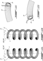
- the core 24 with the surrounding fibers layers 26 may be embedded in a heat-shrink tube 28 (see FIG. 9A ) or wrapped in a shrink tape 30 (see FIG. 9B ) or a coextruded flexible thermoplastic sheath or covered by a sprayed plastic film for example.
- the angular positioning of the fibers within the wire of the spring i.e. the orientation angle of the fibers relative to the direction (Y) of the wire coiled into the spring, and the sequence of the fibers starting from the fiber closest to the center of the section of the wire to the fiber the most remote therefrom, are selected depending on the direction of winding.
- FIGs. 10C and 10D show wires comprising a core 24 and a symmetrical stacking sequence of composite lamina comprising an outermost layer 34, located on the outer surface of the wire, intermediate layers 32 and innermost layer 36, located between the intermediate layers and the core 24, made of fibers impregnated in resin; for a given layer, an angular positioning of the fibers relative to the axis (Y) is selected and the layer is wound accordingly relative to the core 24 of the wire 12.
- the stacking sequence may be balanced, i.e. with a same number of layers or a same quantity of fibers oriented at + ⁇ ° than at - ⁇ ° relative to the axis (Y) of the spring wire; or the stacking sequence may be unbalanced, with a higher number of layers or higher quantity of fibers oriented at - ⁇ ° than oriented at + ⁇ ° relative to the axis (Y) of the spring wire (see FIGs. 10B, 10D ).
- the stacking sequence may be balanced, i.e. with a same number of layers or a same quantity of fibers oriented at + ⁇ ° than at - ⁇ ° relative to the axis (Y) of the spring wire; or unbalanced, i.e. with a higher number of layers or higher quantity of fibers oriented at + ⁇ ° than at - ⁇ ° relative to the axis (Y) of the spring wire (see FIGs. 10A, 10C ).
- the angular positioning of the fibers i.e. the orientation angle of the fibers relative to the axis (Y) of the spring wire, is selected depending on the direction of the spring winding direction about the spring axis (X), according to target characteristics of the spring including: high natural frequency of the spring, resistance to buckling of the spring, and resistance to tensile and compressive stress components induced by application of a compressive load on the spring.
- target characteristics of the spring including: high natural frequency of the spring, resistance to buckling of the spring, and resistance to tensile and compressive stress components induced by application of a compressive load on the spring.
- the angular layout of the fibers in a compression coil spring with a right winding or with a left winding direction may be as follows:
- the number of fiber layers, i.e. layers of fibers within a thermoplastics or thermoset resin matrix, or the quantity of fibers within the wire 12 may be selectively varied along a length of the wire; for example the number of fiber layers or the quantity of fibers within the wire 12 may be lower at the ends 40, 42 of the spring than along the length thereof in between these ends 40, 42.
- FIG. 11 for example shows a compression coil spring with a right winding direction, with tapered terminal ends 40, 42.
- the coil spring may have thickened ends as shown for example in FIG. 20B .
- the number of fiber layers or the quantity of fibers within the wire 12 may be selectively adjusted to tailor a cross section of the wire, which may be circular, polygonal such as square or rectangular or hexagonal for example, convex or ovoid or potato-like for example, as will be discussed hereinbelow in relation to FIGs. 12 .
- the geometry of the cross section of the spring wire may thus be selected based upon the intended use of the spring.
- FIG. 21 shows a wire having a polygonal cross section at an end thereof for stability of the spring, while the remaining cross section thereof is circular,
- Fiber fabrics may be inserted between the layers, to yield non-axisymmetric fiber layer placement around the core, as will be discussed hereinbelow in relation to FIG. 13 .
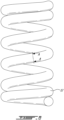
- the coil spring may have a constant pitch as illustrated for example in FIG.1 , or a variable pitch as illustrated for example in FIG.15 .
- the coil spring may have a cylindrical shape as illustrated for example in FIGs. 1 and 15 , a conical shape as illustrated for example in FIG. 16 , a barrel shape as illustrated for example in FIG. 17 , or an hourglass shape as illustrated for example in FIG. 18 .
- the coil spring may have open ends as illustrated for example in FIG.1 or closed ends as can be seen for example in FIG.8 , ground ends ( FIG. 19 ) or unground ends ( FIG. 1 ).
- a composite, non-axisymmetric or axisymmetric, uncured, i.e. unsolidified hence flexible, preform comprising a core and at least two fiber layers is fabricated.
- the uncured preform 25 may be straight ( FIG. 14A ) or non-straight ( FIG. 14B ), yet flexible. Then, during a coiling step, the uncured preform 25 is selectively oriented into a spring according to target performances of the spring. All these steps may be performed at ambient temperature.
- an external envelope of a shrinkable plastic material such as a tubing 28 or a tape 30 as discussed hereinabove in relation to FIGs. 9 for example, may be positioned around the uncured preform 25 before shaping.
- an external envelope may insure a uniform distribution of the resin while it is still in a liquid form, as this external envelop, being impervious, contains the resin and insures a correct wetting of the previously orientated fibers before the solidification of the matrix. It can also insure a correct compression of the wetted fibers as well as insuring a correct final fiber-to-resin ratio.
- the external envelope may then be removable from the spring once formed, after curing. However, it may be decided to keep it in the final spring as will be discussed hereinbelow.
- a non-axisymmetric geometry of the wire may be achieved by at least one of: 1) selecting a core of a non-axisymmetric cross section, 2) selecting a non-axisymmetric placement of the fiber layers about the core, 3) by selectively selecting the ratio between the fiber and the resin, and 4) by lateral displacement of the core 24 of the wound preform 25 prior to curing (see FIG. 22 ).
- the core may be selected as an ovoid, a prismatic or a potato-like core for example.
- Non-axisymmetric fiber layers placement may be achieved by inserting fiber fabrics between the layers of the preform, as shown in FIG. 13 for example.
- These fabrics 50, 51, 52, 53, 54 may be of different compositions: mat, cloth or unidirectional; they may be combined into a specific stacking (51, 52) of any of these types of fabrics.
- These inserted fabrics may be layered on only a portion of the periphery of the preform or extent over the whole circumference of the preform.
- a combination of different fabrics (53, 54) may be used to cover the whole periphery of the cross section of the preform to achieve different properties in different portions of the wire of the resulting spring.
- the resulting preforms 25 may thus have a circular, a polygonal such as square or rectangular or hexagonal ( FIG. 12B ), convex or ovoid ( FIG. 12A ) or potato-like ( FIG. 12C ) cross sections, resulting into corresponding cross sections of the wire 12.
- the preform may be fabricated to provide rigidified or more flexible lengths of the spring wire along the longitudinal axis (Y) of the spring wire, without modifying the composition of the composite material used.
- a further way of achieving non-axisymmetric placement of the fibers relative to the axis (Y) of the wire is to insert a cable within the hollow core 24 and then applying a tension on each end of the cable thereby deflecting the core 24 along its length towards the inner side of the wound preform while still uncured, before curing.
- the preform 25 is shown with a first constant diameter ⁇ d1 over a length L 1 thereof, and an increasingly larger diameter along a length L 2 on each end thereof (only on end shown), until a diameter of the cross section at the ends thereof ⁇ d2 > ⁇ d1.
- the resulting spring shown in FIG. 20B thus comprises thickened ends 34, i.e. of a diameter ⁇ d2 larger than the diameter ⁇ d1 along the remaining part of its length.
- Such a thickening of the ends of the spring wire 12 allows precompression of the spring while minimizing contact between terminal coils of the spring, which might otherwise induce mechanical damages thereto.
- Providing a transition length L 2 of increasing diameter from ⁇ d1 to ⁇ d2 prevents concentration of stresses.
- the resulting spring is then characterized by a linearly varying spring constant, without dead coils and resistant to mechanical stresses submitted locally.
- the preform may be fabricated with a linearly varying diameter of its cross section, with tapered extremities for example, so that the resulting spring has tapered ends (see for example FIG. 11 ), thereby suppressing a grinding step as typically done on the art.
- the cross section of the wire of the resulting spring may be variable according to the position along the length of the spring.
- FIG. 23 shows an hourglass-shape compression spring comprising a last coil of a diameter ⁇ D 2 greater than the mean spring diameter ⁇ D 1 , thereby providing an increased contact surface, which eliminates dead coils or the use of a compensation plate for stability, as typically done in the art.
- FIG. 24 shows another embodiment comprising forming the helicoidal section and then overmolding a plate geometry 60 of a selected diameter and thickness at the end coils, thereby ensuring that all coils of the spring are operational.
- Such overmolding of the end coils may be done directly on the wound preform using a bulk molding compound (BMC) such as a polyester /fiber compound by pressure die-casting for example (see FIG. 25 )
- BMC bulk molding compound
- the helical forming during the coiling step involves a curvature, i.e. a length difference between the inner and outer sides of the spring, which determines the effective angle at which the fibers are positioned in the resulting spring once the shaping is complete.
- the angle placement of the fibers used for the realization of the straight preform is thus selected according to the mean diameter of the spring, as well as the position from the center of the preform and the desired angle on the inner side of the spring, where stresses are maximal.
- the angle placement of the fibers of the preform may be modified along its length considering the final geometry, aiming for an optimal fibers orientation on the inner side of the spring for the whole spring.
- the core 24 may be a flexible plastic tube in which conductive elements such as metallic filaments, including coated fibers for example, or twisted wires are integrated, i.e. encapsulated, thereby allowing the use of an electrical source to generate the heat required to cure the thermoset resin matrix such as by resistance and induction heating.
- the outermost layer of the preform may comprise electrical conductive elements such as fibers or filaments to allow curing the resin matrix and thus the solidification of the preform. Solidification may also be achieved through other methods such as through microwave or radiation heating.
- the flexible tube can be removed after curing, yielding an inner cavity in the cross section of the resulting spring and thus a reduced weight of the spring.
- the inner cavity of the core 24 may be used to add selected characteristics to the spring by housing a functional element.
- a functional element For instance, it may be filled with a viscoelastic or a thixotropic material allowing for a damping effect.
- Optic fibers, sensor gauges or thin wire cables may be inserted as sensors for mechanical properties based on inductive effect, deflection, deformations for example.
- the core 24 may be made of metallic wires in a twisted form, in the way of a steel cable for example.
- the core 24 may be formed with an undulated surface that may improve the adherence with the wounded reinforcing fibers of the preform and yield an increased better overall strength of the coil spring.
- the wire may be provided with an external envelope such as a heat-shrink tube 28 or wrapped in a shrink tape 30 or a coextruded flexible thermoplastic sheath or covered by a sprayed plastic film.
- an external envelope such as a heat-shrink tube 28 or wrapped in a shrink tape 30 or a coextruded flexible thermoplastic sheath or covered by a sprayed plastic film.
- Such an external envelope may protect the spring from damages caused by the impacts and wear from projections of rocks, mud, sand or any other debris, to which suspension springs, for instance, are typically exposed, in on-road vehicles, such as cars and trucks, and in off-road vehicles, such as motorcycles, ATVs and snowmobiles for example. Furthermore, the external envelope may protect the spring from stresses due to weather conditions such as rain, or prolonged exposition to humidity or sunlight, or to any chemicals prone to be in contact with the spring in use, such as for example de-icing salts, sea water, etc.
- the external envelope may also be selected as a colored or luminescent sheath, or as a layer incorporating patterns, drawings, logos or the like, as a substitute for traditional finishing processes such as painting, labelling or decals application.
- the external envelope may also be selected as a layer providing surface finish (roughness), embossment or texturing for example.
- the external envelope may be selected as a transparent sheath, thereby letting the rough resin color show.
- This color may be modified by adding colored or luminescent pigment to the resin.
- a composite helical spring designed for compressive force, with either a constant pitch or a variable pitch, in a range of shapes such as conical, barrel, hourglass forms etc., a range of wire cross sections, and a range of ends type, i.e. open ends, closed ends, tapered ends, thickened ends, ground, unground ends.
- the present composite coil springs may be used in vehicle suspensions systems such as automotive suspensions, snowmobiles suspensions, off-road vehicles suspensions and recreational vehicles suspensions for example.
- a method for fabrication of a composite coil spring generally comprising fabricating a preform, forming the preform into a coil spring shape and then solidifying it by using a heating source.
- two identical preforms having a same core, same inner layers at same angular positioning of fibers relative to the axis (Y), same amount of fibers and fiber-to-resin ratio were fabricated. Both preforms were coiled with a same number of turns around an axis (X) to yield a same spring mean diameter ( ⁇ D), a same cross section diameter (d) and a same free height (h). The difference was the angular positions of the outermost layer, which were opposite. Both springs were tested under compression until they broke. Table 1 below shows the measured results.
- Table 1 records the deflection of the springs when the springs broke, the corresponding load at break and, in the third column, an estimation of the energy stored. It appears that for a given winding direction of the coil spring, there is a preferential orientation of the outermost layer teter as more energy can be stored in Spring B compared to Spring A.
- a method comprising selectively fabricating a preform and combining the winding direction given to a coil spring, the direction of stress when the spring is compressed, and the anisotropic properties of the composite material of the spring wire, according to a target compression spring and optimized stored and restored in energy by the compression spring per unit mass.
Landscapes
- Engineering & Computer Science (AREA)
- Mechanical Engineering (AREA)
- General Engineering & Computer Science (AREA)
- Chemical & Material Sciences (AREA)
- Composite Materials (AREA)
- Textile Engineering (AREA)
- Springs (AREA)
- Laminated Bodies (AREA)
- Wire Processing (AREA)
Claims (20)
- Verbundfeder (10; 14), hergestellt aus einem Draht (12) mit einer Längsachse (Y) und um eine Federachse (X) in einer Wickelrichtung gebogen, wobei der Draht (12) folgendes umfasst:einen Kern (24); undFaserschichten, die um den Kern (24) gewickelt sind;wobei die Faserschichten innerste Schichten (36), die dem Kern (24) am nächsten sind, eine äußerste Schicht (34) und Zwischenschichten (32) zwischen den innersten Schichten (36) und der äußersten Schicht (34) umfassen, wobei eine Orientierung jeder der Faserschichten relativ zur Federachse ausgewählt wird, entlang einer Länge des Kerns in Abhängigkeit von der Wickelrichtung des Drahtes um die Federachse gewählt wird, um mindestens eine der folgenden Eigenschaften einzustellen: hohe Eigenfrequenz der Feder, Knickbeständigkeit und Beständigkeit gegen Zug- und Druckspannungskomponenten, die durch eine Druckbelastung der Feder induziert werden,dadurch gekennzeichnet, dass die Ausrichtung der äußersten Schicht (34) ein negativer Winkel (-Θ) ist, wie in Abbildung 7 der Zeichnungen dargestellt, in einem Bereich zwischen -35° und -55° relativ zur Längsachse (Y) für die gegebene Wickelrichtung der Feder (10) bei Rechtswicklung, oderdie Ausrichtung der äußersten Schicht (34) ein positiver Winkel (+Θ) ist, wie in Abbildung 7 der Zeichnungen dargestellt, in einem Bereich zwischen +35° und +55° relativ zur Längsachse (Y) für die gegebene Wickelrichtung der Feder (14) bei Linkswicklung.
- Verbundfeder (10; 14) nach Anspruch 1, wobei die gegebene Wickelrichtung der Feder (14) die Linkswicklung ist:die innersten Schichten (36) relativ zur Längsachse (Y) des Drahtes (12) in mindestens einem der folgenden Fälle ausgerichtet sind: i) in einem Winkel in einem Bereich zwischen etwa 0° und etwa + 15°; ii) in einem Winkel in einem Bereich zwischen +75° und +90°; iii) in einem Winkel in einem Bereich zwischen 0° und etwa -15°; und iv) in einem Winkel in einem Bereich zwischen -75° und etwa -90°; unddie Zwischenschichten (32) in einem Winkel in einem Bereich zwischen: i) +35° und +55° und ii) -35° und -55° relativ zur Längsachse (Y) des Drahtes (12) ausgerichtet sind.
- Verbundfeder (10; 14) nach Anspruch 1, wobei für die gegebene Wickelrichtung der Feder (10), die die Rechtswicklung ist,die innersten Schichten (36) relativ zur Längsachse (Y) des Drahtes (12) in mindestens einem der folgenden Fälle ausgerichtet sind: i) einem Winkel in einem Bereich zwischen etwa 0° und etwa +15°; ii) einem Winkel in einem Bereich zwischen +75° und +90°; iii) einem Winkel in einem Bereich zwischen 0° und etwa -15°, und iv) einem Winkel in einem Bereich zwischen -75° und etwa - 90°; undZwischenschichten (32) in einem Winkel in einem Bereich zwischen: i) +35° und +55° und ii) -35° und -55° relativ zur Längsachse (Y) des Drahtes (12) ausgerichtet sind.
- Verbundfeder (10; 14) nach Anspruch 1, wobei der Draht (12) mindestens einen der folgenden Querschnitte aufweist: einen kreisförmigen, einen polygonalen, einen konvexen und einen ovoiden Querschnitt entlang mindestens eines Teils seiner Länge.
- Verbundfeder (10; 14) nach Anspruch 1, wobei der Draht (12) zu einer Federwicklung mit mindestens einer der folgenden Eigenschaften gewickelt ist: eine konstante Steigung, eine variable Steigung, eine zylindrische Form, eine konische Form, eine Tonnenform, eine Sanduhrform, eine Feder mit offenen Enden und eine Feder mit geschlossenen Enden.
- Verbundfeder (10; 14) nach Anspruch 1, wobei:für die gegebene Wickelrichtung der Feder (10), die die Rechtswicklung ist, eine Anzahl von Faserschichten, die um -θ° relativ zur Längsachse (Y) des Drahtes (12) ausgerichtet sind, größer oder gleich einer Anzahl von Faserschichten ist, die um +θ° relativ zur Längsachse (Y) des Drahtes (12) ausgerichtet sind; undfür die gegebene Wickelrichtung der Feder (14), die die Linkswicklung ist, eine Anzahl von Faserschichten, die um +θ° relativ zur Längsachse (Y) des Drahtes (12) ausgerichtet sind, größer oder gleich einer Anzahl von Faserschichten ist, die um -θ° relativ zur Längsachse (Y) des Drahtes (12) ausgerichtet sind.
- Verbundfeder (10; 14) nach Anspruch 1, wobei der Draht (12) mindestens eines der folgenden Merkmale aufweist: verjüngte Enden, verdickte Enden, geschliffene Enden, ungeschliffene Enden, polygonale kreuzförmige Enden und vergossene Enden.
- Verbundfeder (10; 14) nach Anspruch 1, wobei der Kern (24) ein Hohlrohr ist.
- Verbundfeder (10; 14) nach Anspruch 8, die ferner mindestens ein thermisch oder elektrisch leitendes Element umfasst, das durch das Hohlrohr verläuft.
- Verbundfeder (10; 14) nach Anspruch 8, wobei der Kern (24) ein Funktionselement enthält.
- Verbundfeder (10; 14) nach Anspruch 1, wobei der Draht (12) mindestens ein thermisch oder elektrisch leitendes Element umfasst.
- Verbundfeder (10; 14) nach Anspruch 1, wobei der Draht (12) eine äußere Umhüllung (28; 30) aufweist, wobei die äußere Umhüllung (28; 30) mindestens eine der folgenden ist: i) eine Schutzumhüllung; ii) eine Oberflächenumhüllung; und iii) eine transparente Umhüllung.
- Verbundfeder (10; 14) nach Anspruch 1, wobei der Draht (12) eine transparente äußere Umhüllung (28; 30) aufweist, und wobei mindestens eine der Faserschichten entweder: i) ein raues oder ii) ein pigmentiertes Harz aufweist.
- Verfahren zur Herstellung einer Verbundfeder (10; 14) mit einer Vielzahl von Faserschichten und mit einer gegebenen Wickelrichtung entlang einer Achse (X), Folgendes umfassend:A) Herstellen einer ungehärteten Verbundvorform (25) mit einem Kern (24) und mindestens einer innersten Schicht (36), die dem Kern (24) am nächsten liegt, einer äußersten Schicht (34) und Zwischenschichten (32), die zwischen der mindestens einen innersten Schicht (36) und der äußersten Schicht (32) gewickelt sind;B) Auswählen einer Ausrichtung der äußersten Schicht (34) relativ zu einer Längsachse der Vorform (25) entlang einer Länge der Vorform (25) in Abhängigkeit von der gegebenen Wickelrichtung der Feder (10; 14),wobei die Ausrichtung der äußersten Schicht (34) ein negativer Winkel (-Θ) ist, wie in Abbildung 7 der Zeichnungen dargestellt, in einem Bereich zwischen -35° und -55° relativ zur Längsachse (Y) für die gegebene Wickelrichtung der Feder (10), die eine Rechtswickelung ist, oderdie Ausrichtung der äußersten Schicht (34) ein positiver Winkel (+Θ) ist, wie in Abbildung 7 der Zeichnungen dargestellt, in einem Bereich zwischen +35° und +55° relativ zur Längsachse (Y) für die gegebene Wickelrichtung der Feder (14), die eine Linkswicklung ist;C) Formen der ungehärteten Vorform (25) relativ zur Federachse (X) zur Feder (10; 14) der gegebenen Wicklungsrichtung; undD) Aushärten.
- Verfahren nach Anspruch 14, das mindestens eines der folgenden Merkmale umfasst: i) Auswählen des Kerns (24), um einen nicht-achsensymmetrischen Querschnitt zu erzielen, ii) Auswählen einer nicht-achsensymmetrischen Anordnung der Faserlagen um den Kern (24), iii) Auswählen eines Faser-Harz-Verhältnisses und iv) Bewirken einer seitlichen Verschiebung des Kerns (24) der ungehärteten Vorform (25).
- Verfahren nach Anspruch 14, das mindestens eines der folgenden Merkmale umfasst: i) selektives Positionieren der innersten, äußersten und Zwischenschichten (36; 34; 32) entlang der Länge der Vorform (25), ii) Variieren eines Faser-Harz-Verhältnisses entlang der Länge der Vorform (25), und iii) Auswählen des Kerns (24), um einen variierenden Querschnitt entlang seiner Länge zu erzielen.
- Verfahren nach Anspruch 14, wobei das Formen der ungehärteten Vorform (25) zur Feder (10; 14) der gegebenen Wickelrichtung das Wickeln der Vorform (25) in der gegebenen Wickelrichtung um die Federachse (X) mit mindestens einer der folgenden Formen umfasst: eine konstante Steigung, eine variable Steigung, eine zylindrische Form, eine konische Form, eine Tonnenform, eine Sanduhrform, eine Feder mit offenen Enden und eine Feder mit geschlossenen Enden.
- Verfahren nach Anspruch 14, wobei die mindestens eine innerste Schicht eine Vielzahl von innersten Schichten umfasst, und wobei das Verfahren das Einstellen von mindestens einem der folgenden Merkmale umfasst:A) eine hohe Eigenfrequenz der Feder (10; 14) durch Ausrichten der innersten Schichten (36) in einem Winkel in einem Bereich zwischen: i) +75° und +90° und ii) -75° und -90° relativ zur Längsachse der Vorform (25); undB) eine Knickfestigkeit der Feder durch Ausrichten der innersten Schichten (36) in einem Winkel in einem Bereich zwischen: i) 0° und +15° und ii) 0° und -15°, relativ zur Längsachse der Vorform (25).
- Das Verfahren nach Anspruch 14, folgende Auswahl umfassend:i) für die gegebene Wickelrichtung der Feder (10), die die Rechtswicklung ist, eine Vielzahl von Faserschichten, die um - θ° relativ zur Längsachse der Vorform (25) ausgerichtet sind, größer oder gleich einer Anzahl von Faserschichten ist, die um +θ° relativ zur Längsachse der Vorform (25) ausgerichtet sind; undii) für die gegebene Wickelrichtung der Feder (14), die die Linkswicklung ist, eine Vielzahl von Faserschichten, die um +θ° relativ zur Längsachse der Vorform (25) ausgerichtet sind, größer oder gleich einer Anzahl von Faserschichten ist, die um -θ° relativ zur Längsachse der Vorform (25) ausgerichtet sind.
- Verfahren nach Anspruch 14, umfassend das Ausrichten der Zwischenschichten (32) in einem Winkel in einem Bereich, der zwischen: i) +35° und +55° und ii) -35° und -55°, relativ zur Längsachse der Vorform (25) ist.
Applications Claiming Priority (2)
| Application Number | Priority Date | Filing Date | Title |
|---|---|---|---|
| US201762549602P | 2017-08-24 | 2017-08-24 | |
| PCT/CA2018/050993 WO2019036801A1 (en) | 2017-08-24 | 2018-08-16 | HELICAL SPRING AND METHOD FOR MANUFACTURING THE SAME |
Publications (4)
| Publication Number | Publication Date |
|---|---|
| EP3673184A1 EP3673184A1 (de) | 2020-07-01 |
| EP3673184A4 EP3673184A4 (de) | 2021-05-05 |
| EP3673184C0 EP3673184C0 (de) | 2024-11-06 |
| EP3673184B1 true EP3673184B1 (de) | 2024-11-06 |
Family
ID=65438223
Family Applications (1)
| Application Number | Title | Priority Date | Filing Date |
|---|---|---|---|
| EP18847968.7A Active EP3673184B1 (de) | 2017-08-24 | 2018-08-16 | Schraubenfeder und herstellungsverfahren dafür |
Country Status (9)
| Country | Link |
|---|---|
| US (1) | US11248674B2 (de) |
| EP (1) | EP3673184B1 (de) |
| JP (1) | JP7227251B2 (de) |
| KR (1) | KR102640878B1 (de) |
| CN (1) | CN111465778B (de) |
| BR (1) | BR112020003795A2 (de) |
| CA (1) | CA3072836C (de) |
| MX (1) | MX2020002097A (de) |
| WO (1) | WO2019036801A1 (de) |
Families Citing this family (8)
| Publication number | Priority date | Publication date | Assignee | Title |
|---|---|---|---|---|
| DE102018129549B9 (de) * | 2018-11-23 | 2022-08-18 | Action Composites Hightech GmbH | Gestaltung der Enden von Schraubenfedern |
| CN113646556B (zh) * | 2019-07-01 | 2023-06-23 | 三菱制钢株式会社 | 具有碳纤维和玻璃纤维层的复合线圈弹簧 |
| DE102020100932B4 (de) * | 2020-01-16 | 2021-12-02 | Efaflex Tor- Und Sicherheitssysteme Gmbh & Co. Kg | Feder für ein Hubtor mit einer Überwachungsvorrichtung, System mit einem Tor und der Feder mit der Überwachungsvorrichtung, sowie Verfahren hierfür |
| CN111331877B (zh) * | 2020-02-17 | 2022-05-17 | 浙江理工大学 | 一种变刚度复合材料螺旋弹簧的制备方法 |
| JP7545350B2 (ja) * | 2021-03-05 | 2024-09-04 | 日立Astemo株式会社 | 電磁式燃料噴射弁 |
| KR102394598B1 (ko) * | 2021-06-07 | 2022-05-06 | 한국항공우주연구원 | 섬유 와인딩 장치 |
| CN114872350A (zh) * | 2022-05-18 | 2022-08-09 | 奇瑞汽车股份有限公司 | 螺旋弹簧的制造方法和变节距螺旋弹簧 |
| CN115871265A (zh) * | 2022-12-06 | 2023-03-31 | 增城华昌塑料五金模具有限公司 | 一种复合材料螺旋弹簧的制造方法 |
Citations (1)
| Publication number | Priority date | Publication date | Assignee | Title |
|---|---|---|---|---|
| DE102013016483A1 (de) * | 2013-10-04 | 2014-07-24 | Daimler Ag | Faserverbund-Torsionsfeder |
Family Cites Families (52)
| Publication number | Priority date | Publication date | Assignee | Title |
|---|---|---|---|---|
| JPS63188346U (de) * | 1987-05-28 | 1988-12-02 | ||
| DE4224951C1 (de) | 1992-07-29 | 1993-11-04 | Krupp Ag Hoesch Krupp | Verfahren und vorrichtung zum herstellen von gekruemmten schraubenfedern |
| DE4224962C1 (de) | 1992-07-29 | 1993-10-21 | Krupp Ag Hoesch Krupp | Verfahren und Vorrichtung zum Herstellen von gekrümmten Schraubenfedern |
| GB9403008D0 (en) | 1993-03-05 | 1994-04-06 | Luk Lamellen & Kupplungsbau | Helical spring |
| JP3009311B2 (ja) * | 1993-08-04 | 2000-02-14 | 東邦レーヨン株式会社 | 繊維強化樹脂製コイルスプリングおよびその製造方法 |
| JPH08224632A (ja) | 1995-02-22 | 1996-09-03 | Chuo Spring Co Ltd | 円弧状コイルばねの製造方法 |
| FR2739044B1 (fr) | 1995-09-22 | 1997-10-24 | Metallurg De Saint Urbain Amsu | Procede de fabrication de ressorts helicoidaux courbes, ressorts ainsi obtenus et dispositifs pour la mise en oeuvre du procede |
| JP2000129359A (ja) | 1998-10-19 | 2000-05-09 | Suncall Corp | クラッチディスク用アーク状スプリング製造方法 |
| JP4601108B2 (ja) | 2000-01-28 | 2010-12-22 | 中央発條株式会社 | 湾曲コイルばね及び該湾曲コイルばねの製造方法 |
| US20020190451A1 (en) * | 2001-06-01 | 2002-12-19 | The University Of Akron | Fiber-reinforced composite springs |
| JP3760994B2 (ja) * | 2002-04-10 | 2006-03-29 | 村田機械株式会社 | Frpスプリング |
| CN100367432C (zh) * | 2002-09-10 | 2008-02-06 | 株式会社克拉比 | 编码型热熔断器和片型热熔断器 |
| DE50304974D1 (de) | 2003-11-22 | 2006-10-19 | Schroer Bernt | Verfahren zur Herstellung einer gekrümmten Spiralfeder und Vorrichtung zur Durchführung des Verfahrens |
| JP2006226327A (ja) * | 2005-02-15 | 2006-08-31 | Kyoto Institute Of Technology | Frp製コイルばね及びその生産方法 |
| CN101184934B (zh) * | 2005-05-31 | 2010-12-01 | 日本发条株式会社 | 螺旋弹簧 |
| JP5014660B2 (ja) | 2006-03-31 | 2012-08-29 | 村田発條株式会社 | アーク状コイルスプリングの製造方法 |
| JP2007278438A (ja) * | 2006-04-10 | 2007-10-25 | I Chu Spring Co Ltd | 複合衝撃吸収材料、製造方法およびその製品 |
| CN101092014B (zh) | 2007-05-16 | 2010-08-11 | 邵承玉 | 一种汽车液力变矩器用弧形弹簧的专用弧形弹簧立定处理机 |
| US7857294B2 (en) * | 2008-03-28 | 2010-12-28 | Spencer Composites Corporation | Composite springs and methods of manufacture |
| CN201818683U (zh) | 2010-02-24 | 2011-05-04 | 钱江弹簧(北京)有限公司 | 弧形弹簧 |
| CN101786221B (zh) | 2010-02-24 | 2012-07-04 | 钱江弹簧(北京)有限公司 | 弧形弹簧的加工方法 |
| CN201714881U (zh) | 2010-06-29 | 2011-01-19 | 福州立洲弹簧有限公司 | 双质量飞轮弧形弹簧 |
| DE102011078543A1 (de) | 2011-07-01 | 2013-01-03 | Oskar Schwenk Gmbh & Co Kg | Schraubenfeder |
| CN102501009B (zh) | 2011-10-27 | 2014-12-24 | 杭州富春弹簧有限公司 | 一种弧形弹簧的加工工艺 |
| CN103121069B (zh) | 2011-11-18 | 2015-08-05 | 邵承玉 | 弧形弹簧成形机 |
| FR2983954B1 (fr) * | 2011-12-13 | 2014-09-12 | Renault Sa | Ressort avec capteur de deformation integre. |
| CN102699242B (zh) | 2012-04-13 | 2014-04-02 | 杭州富春弹簧有限公司 | 一种弧形弹簧的加工工艺 |
| CN102699239A (zh) | 2012-04-13 | 2012-10-03 | 杭州富春弹簧有限公司 | 弧形弹簧热成型装置 |
| CN202555729U (zh) | 2012-04-13 | 2012-11-28 | 杭州富春弹簧有限公司 | 弧形弹簧的成型工装夹具 |
| WO2014008466A2 (en) | 2012-07-06 | 2014-01-09 | Barnes Group Inc. | High fatigue arcuate spring |
| US8857801B2 (en) * | 2012-07-18 | 2014-10-14 | Mssc Us | Composite coil spring |
| TWM458255U (zh) | 2013-03-19 | 2013-08-01 | Chin-Yi Liao | 線材加工設備 |
| EP2981732B1 (de) * | 2013-04-03 | 2019-06-19 | Mubea Carbo Tech GmbH | Hybridfedervorrichtung |
| JP5855600B2 (ja) | 2013-05-17 | 2016-02-09 | 京浜金属工業株式会社 | アーク状コイルスプリングの製造装置 |
| JP5914413B2 (ja) | 2013-05-29 | 2016-05-11 | 京浜金属工業株式会社 | アーク状コイルスプリングの製造装置 |
| CN103567716B (zh) | 2013-08-15 | 2016-06-08 | 杭州富春弹簧有限公司 | 超高应力双离合器弹簧制造工艺 |
| CN203532601U (zh) | 2013-10-14 | 2014-04-09 | 福州立洲弹簧有限公司 | 携动盘弧形双形弹簧 |
| DE102014211096A1 (de) * | 2014-06-11 | 2015-12-17 | Thyssenkrupp Ag | Torsionsbelastetes stabförmiges Bauteil mit unterschiedlichen Faserverstärkungen für Zug- und Druckbelastung |
| WO2016002812A1 (ja) * | 2014-06-30 | 2016-01-07 | 矢崎総業株式会社 | 複数回路ケーブル |
| CN204025474U (zh) | 2014-07-02 | 2014-12-17 | 安庆谢德尔汽车零部件有限公司 | 一种喇叭型压缩弹簧 |
| WO2016006616A1 (ja) | 2014-07-07 | 2016-01-14 | アイシン・エィ・ダブリュ株式会社 | コイルスプリング |
| CN203955972U (zh) | 2014-07-28 | 2014-11-26 | 福州立洲弹簧有限公司 | 弧形弹簧成型机 |
| CN104190829B (zh) | 2014-08-13 | 2016-06-08 | 曲阜天博汽车电器有限公司 | 弧形弹簧的制作工艺 |
| EP3189165B1 (de) | 2014-09-04 | 2020-09-02 | ThyssenKrupp Federn und Stabilisatoren GmbH | Verfahren zum herstellen von kaltgeformten stahlfedern |
| US11064891B2 (en) | 2014-09-05 | 2021-07-20 | Canon Kabushiki Kaisha | Object information acquiring apparatus |
| JP6420690B2 (ja) | 2015-02-26 | 2018-11-07 | 日本発條株式会社 | コイリングマシンと、コイルばねの製造方法 |
| KR101785067B1 (ko) | 2015-09-25 | 2017-10-12 | 주식회사 토룩 | 직렬 탄성 액추에이터를 위한 아크형 압축 스프링 모듈 |
| JP6502235B2 (ja) * | 2015-10-29 | 2019-04-17 | 日本発條株式会社 | 弾性部材用線材および弾性部材 |
| CN205533923U (zh) | 2016-05-03 | 2016-08-31 | 立洲(青岛)五金弹簧有限公司 | 万向轮弧形簧 |
| JP6113891B1 (ja) | 2016-05-25 | 2017-04-12 | 株式会社システムテクニカ | アーク状コイルスプリングの製造方法及び製造装置 |
| CN107309377A (zh) | 2017-07-11 | 2017-11-03 | 苏州切浦汽车零部件有限公司 | 弧形弹簧成型机及弧形弹簧的成型方法 |
| CN107838329B (zh) | 2017-10-28 | 2020-03-17 | 曲阜天博汽车电器有限公司 | 螺旋压缩偏心弹簧的制作工艺及其弹簧产品 |
-
2018
- 2018-08-16 JP JP2020531799A patent/JP7227251B2/ja active Active
- 2018-08-16 US US16/641,617 patent/US11248674B2/en active Active
- 2018-08-16 CA CA3072836A patent/CA3072836C/en active Active
- 2018-08-16 WO PCT/CA2018/050993 patent/WO2019036801A1/en not_active Ceased
- 2018-08-16 MX MX2020002097A patent/MX2020002097A/es unknown
- 2018-08-16 CN CN201880054967.4A patent/CN111465778B/zh active Active
- 2018-08-16 EP EP18847968.7A patent/EP3673184B1/de active Active
- 2018-08-16 BR BR112020003795-8A patent/BR112020003795A2/pt not_active Application Discontinuation
- 2018-08-16 KR KR1020207007710A patent/KR102640878B1/ko active Active
Patent Citations (1)
| Publication number | Priority date | Publication date | Assignee | Title |
|---|---|---|---|---|
| DE102013016483A1 (de) * | 2013-10-04 | 2014-07-24 | Daimler Ag | Faserverbund-Torsionsfeder |
Also Published As
| Publication number | Publication date |
|---|---|
| KR102640878B1 (ko) | 2024-02-27 |
| EP3673184C0 (de) | 2024-11-06 |
| US20210156442A1 (en) | 2021-05-27 |
| KR20200045509A (ko) | 2020-05-04 |
| US11248674B2 (en) | 2022-02-15 |
| MX2020002097A (es) | 2020-09-18 |
| EP3673184A4 (de) | 2021-05-05 |
| CA3072836C (en) | 2021-11-09 |
| CN111465778A (zh) | 2020-07-28 |
| BR112020003795A2 (pt) | 2020-09-08 |
| CN111465778B (zh) | 2022-05-31 |
| CA3072836A1 (en) | 2019-02-28 |
| EP3673184A1 (de) | 2020-07-01 |
| WO2019036801A1 (en) | 2019-02-28 |
| JP7227251B2 (ja) | 2023-02-21 |
| JP2020532697A (ja) | 2020-11-12 |
Similar Documents
| Publication | Publication Date | Title |
|---|---|---|
| US11248674B2 (en) | Coil spring and method of fabrication thereof | |
| CA1154042A (en) | Fiber-reinforced tubular spring | |
| US10240654B2 (en) | Hybrid spring device | |
| CA1130594A (en) | Power transmission shaft | |
| US4555113A (en) | Shaft and a method for producing the same | |
| US7857294B2 (en) | Composite springs and methods of manufacture | |
| CA2877488C (en) | Composite coil spring | |
| US6148885A (en) | Pneumatic tire with band element | |
| DE102022111118A1 (de) | Tank und Verfahren zur Herstellung desselben | |
| WO2017034034A1 (ja) | 弾性部材用線材および弾性部材 | |
| JPH0258493B2 (de) | ||
| WO2017073772A1 (ja) | コイルばね用線材およびコイルばね | |
| EP3369960B1 (de) | Draht für elastisches element und elastisches element | |
| JPS5828029A (ja) | 繊維強化プラスチック製コイルバネおよびその製造方法 | |
| JPS6041246B2 (ja) | 繊維強化プラスチツク製プロペラシヤフト | |
| JPS6032539B2 (ja) | コイルスプリングの製造方法 | |
| JPS5891940A (ja) | 複合材料から成るコイル状バネ | |
| WO2017073771A1 (ja) | 弾性部材用線材および弾性部材 | |
| KR102391001B1 (ko) | 복합재 코일 스프링 및 그 제조방법 | |
| JP3053567B2 (ja) | ゴルフクラブシャフトの製造方法 | |
| JPH0730805B2 (ja) | 繊維強化複合材料製の波形リングバネ | |
| JP2006000496A (ja) | ゴルフクラブ用シャフト |
Legal Events
| Date | Code | Title | Description |
|---|---|---|---|
| STAA | Information on the status of an ep patent application or granted ep patent |
Free format text: STATUS: THE INTERNATIONAL PUBLICATION HAS BEEN MADE |
|
| PUAI | Public reference made under article 153(3) epc to a published international application that has entered the european phase |
Free format text: ORIGINAL CODE: 0009012 |
|
| STAA | Information on the status of an ep patent application or granted ep patent |
Free format text: STATUS: REQUEST FOR EXAMINATION WAS MADE |
|
| 17P | Request for examination filed |
Effective date: 20200220 |
|
| AK | Designated contracting states |
Kind code of ref document: A1 Designated state(s): AL AT BE BG CH CY CZ DE DK EE ES FI FR GB GR HR HU IE IS IT LI LT LU LV MC MK MT NL NO PL PT RO RS SE SI SK SM TR |
|
| AX | Request for extension of the european patent |
Extension state: BA ME |
|
| DAV | Request for validation of the european patent (deleted) | ||
| DAX | Request for extension of the european patent (deleted) | ||
| A4 | Supplementary search report drawn up and despatched |
Effective date: 20210409 |
|
| RIC1 | Information provided on ipc code assigned before grant |
Ipc: F16F 1/366 20060101AFI20210401BHEP Ipc: B29C 70/24 20060101ALI20210401BHEP Ipc: B29C 70/70 20060101ALI20210401BHEP Ipc: F16F 1/04 20060101ALI20210401BHEP Ipc: B29C 53/58 20060101ALI20210401BHEP |
|
| RIN1 | Information on inventor provided before grant (corrected) |
Inventor name: FOURNIER, RENE Inventor name: MASSON, FRANCOIS Inventor name: DESJARDINS, LUC Inventor name: BELANGER, GERMAIN |
|
| STAA | Information on the status of an ep patent application or granted ep patent |
Free format text: STATUS: EXAMINATION IS IN PROGRESS |
|
| 17Q | First examination report despatched |
Effective date: 20230220 |
|
| GRAP | Despatch of communication of intention to grant a patent |
Free format text: ORIGINAL CODE: EPIDOSNIGR1 |
|
| STAA | Information on the status of an ep patent application or granted ep patent |
Free format text: STATUS: GRANT OF PATENT IS INTENDED |
|
| RIC1 | Information provided on ipc code assigned before grant |
Ipc: B29C 53/12 20060101ALI20240430BHEP Ipc: B29C 70/24 20060101ALI20240430BHEP Ipc: B29C 70/70 20060101ALI20240430BHEP Ipc: F16F 1/04 20060101ALI20240430BHEP Ipc: B29C 53/58 20060101ALI20240430BHEP Ipc: F16F 1/366 20060101AFI20240430BHEP |
|
| INTG | Intention to grant announced |
Effective date: 20240527 |
|
| GRAS | Grant fee paid |
Free format text: ORIGINAL CODE: EPIDOSNIGR3 |
|
| GRAA | (expected) grant |
Free format text: ORIGINAL CODE: 0009210 |
|
| STAA | Information on the status of an ep patent application or granted ep patent |
Free format text: STATUS: THE PATENT HAS BEEN GRANTED |
|
| AK | Designated contracting states |
Kind code of ref document: B1 Designated state(s): AL AT BE BG CH CY CZ DE DK EE ES FI FR GB GR HR HU IE IS IT LI LT LU LV MC MK MT NL NO PL PT RO RS SE SI SK SM TR |
|
| REG | Reference to a national code |
Ref country code: GB Ref legal event code: FG4D |
|
| REG | Reference to a national code |
Ref country code: CH Ref legal event code: EP |
|
| REG | Reference to a national code |
Ref country code: DE Ref legal event code: R096 Ref document number: 602018076362 Country of ref document: DE |
|
| REG | Reference to a national code |
Ref country code: IE Ref legal event code: FG4D |
|
| U01 | Request for unitary effect filed |
Effective date: 20241125 |
|
| U07 | Unitary effect registered |
Designated state(s): AT BE BG DE DK EE FI FR IT LT LU LV MT NL PT RO SE SI Effective date: 20241202 |
|
| PG25 | Lapsed in a contracting state [announced via postgrant information from national office to epo] |
Ref country code: HR Free format text: LAPSE BECAUSE OF FAILURE TO SUBMIT A TRANSLATION OF THE DESCRIPTION OR TO PAY THE FEE WITHIN THE PRESCRIBED TIME-LIMIT Effective date: 20241106 Ref country code: IS Free format text: LAPSE BECAUSE OF FAILURE TO SUBMIT A TRANSLATION OF THE DESCRIPTION OR TO PAY THE FEE WITHIN THE PRESCRIBED TIME-LIMIT Effective date: 20250306 |
|
| PG25 | Lapsed in a contracting state [announced via postgrant information from national office to epo] |
Ref country code: ES Free format text: LAPSE BECAUSE OF FAILURE TO SUBMIT A TRANSLATION OF THE DESCRIPTION OR TO PAY THE FEE WITHIN THE PRESCRIBED TIME-LIMIT Effective date: 20241106 |
|
| PG25 | Lapsed in a contracting state [announced via postgrant information from national office to epo] |
Ref country code: NO Free format text: LAPSE BECAUSE OF FAILURE TO SUBMIT A TRANSLATION OF THE DESCRIPTION OR TO PAY THE FEE WITHIN THE PRESCRIBED TIME-LIMIT Effective date: 20250206 |
|
| PG25 | Lapsed in a contracting state [announced via postgrant information from national office to epo] |
Ref country code: GR Free format text: LAPSE BECAUSE OF FAILURE TO SUBMIT A TRANSLATION OF THE DESCRIPTION OR TO PAY THE FEE WITHIN THE PRESCRIBED TIME-LIMIT Effective date: 20250207 |
|
| PG25 | Lapsed in a contracting state [announced via postgrant information from national office to epo] |
Ref country code: PL Free format text: LAPSE BECAUSE OF FAILURE TO SUBMIT A TRANSLATION OF THE DESCRIPTION OR TO PAY THE FEE WITHIN THE PRESCRIBED TIME-LIMIT Effective date: 20241106 |
|
| PG25 | Lapsed in a contracting state [announced via postgrant information from national office to epo] |
Ref country code: RS Free format text: LAPSE BECAUSE OF FAILURE TO SUBMIT A TRANSLATION OF THE DESCRIPTION OR TO PAY THE FEE WITHIN THE PRESCRIBED TIME-LIMIT Effective date: 20250206 |
|
| PG25 | Lapsed in a contracting state [announced via postgrant information from national office to epo] |
Ref country code: SM Free format text: LAPSE BECAUSE OF FAILURE TO SUBMIT A TRANSLATION OF THE DESCRIPTION OR TO PAY THE FEE WITHIN THE PRESCRIBED TIME-LIMIT Effective date: 20241106 |
|
| PG25 | Lapsed in a contracting state [announced via postgrant information from national office to epo] |
Ref country code: SK Free format text: LAPSE BECAUSE OF FAILURE TO SUBMIT A TRANSLATION OF THE DESCRIPTION OR TO PAY THE FEE WITHIN THE PRESCRIBED TIME-LIMIT Effective date: 20241106 |
|
| PG25 | Lapsed in a contracting state [announced via postgrant information from national office to epo] |
Ref country code: CZ Free format text: LAPSE BECAUSE OF FAILURE TO SUBMIT A TRANSLATION OF THE DESCRIPTION OR TO PAY THE FEE WITHIN THE PRESCRIBED TIME-LIMIT Effective date: 20241106 |
|
| U20 | Renewal fee for the european patent with unitary effect paid |
Year of fee payment: 8 Effective date: 20250723 |
|
| PLBE | No opposition filed within time limit |
Free format text: ORIGINAL CODE: 0009261 |
|
| STAA | Information on the status of an ep patent application or granted ep patent |
Free format text: STATUS: NO OPPOSITION FILED WITHIN TIME LIMIT |
|
| 26N | No opposition filed |
Effective date: 20250807 |
|
| PGFP | Annual fee paid to national office [announced via postgrant information from national office to epo] |
Ref country code: GB Payment date: 20250725 Year of fee payment: 8 |
|
| REG | Reference to a national code |
Ref country code: CH Ref legal event code: H13 Free format text: ST27 STATUS EVENT CODE: U-0-0-H10-H13 (AS PROVIDED BY THE NATIONAL OFFICE) Effective date: 20260324 |
|
| PG25 | Lapsed in a contracting state [announced via postgrant information from national office to epo] |
Ref country code: MC Free format text: LAPSE BECAUSE OF FAILURE TO SUBMIT A TRANSLATION OF THE DESCRIPTION OR TO PAY THE FEE WITHIN THE PRESCRIBED TIME-LIMIT Effective date: 20241106 |
|
| PG25 | Lapsed in a contracting state [announced via postgrant information from national office to epo] |
Ref country code: CH Free format text: LAPSE BECAUSE OF NON-PAYMENT OF DUE FEES Effective date: 20250831 |
|
| U1N | Appointed representative for the unitary patent procedure changed after the registration of the unitary effect |
Representative=s name: MARKS & CLERK LLP; GB |