EP3673316B1 - Gekrümmter lichtleiter, abbildungsoptik und hmd - Google Patents
Gekrümmter lichtleiter, abbildungsoptik und hmd Download PDFInfo
- Publication number
- EP3673316B1 EP3673316B1 EP18762798.9A EP18762798A EP3673316B1 EP 3673316 B1 EP3673316 B1 EP 3673316B1 EP 18762798 A EP18762798 A EP 18762798A EP 3673316 B1 EP3673316 B1 EP 3673316B1
- Authority
- EP
- European Patent Office
- Prior art keywords
- light guide
- light
- coupling
- coupling structure
- image
- Prior art date
- Legal status (The legal status is an assumption and is not a legal conclusion. Google has not performed a legal analysis and makes no representation as to the accuracy of the status listed.)
- Active
Links
Images




Classifications
-
- G—PHYSICS
- G02—OPTICS
- G02B—OPTICAL ELEMENTS, SYSTEMS OR APPARATUS
- G02B27/00—Optical systems or apparatus not provided for by any of the groups G02B1/00 - G02B26/00, G02B30/00
- G02B27/01—Head-up displays
- G02B27/017—Head mounted
- G02B27/0172—Head mounted characterised by optical features
-
- G—PHYSICS
- G02—OPTICS
- G02B—OPTICAL ELEMENTS, SYSTEMS OR APPARATUS
- G02B27/00—Optical systems or apparatus not provided for by any of the groups G02B1/00 - G02B26/00, G02B30/00
- G02B27/0081—Optical systems or apparatus not provided for by any of the groups G02B1/00 - G02B26/00, G02B30/00 with means for altering, e.g. enlarging, the entrance or exit pupil
-
- G—PHYSICS
- G02—OPTICS
- G02B—OPTICAL ELEMENTS, SYSTEMS OR APPARATUS
- G02B5/00—Optical elements other than lenses
- G02B5/18—Diffraction gratings
-
- G—PHYSICS
- G02—OPTICS
- G02B—OPTICAL ELEMENTS, SYSTEMS OR APPARATUS
- G02B6/00—Light guides; Structural details of arrangements comprising light guides and other optical elements, e.g. couplings
- G02B6/0001—Light guides; Structural details of arrangements comprising light guides and other optical elements, e.g. couplings specially adapted for lighting devices or systems
- G02B6/0011—Light guides; Structural details of arrangements comprising light guides and other optical elements, e.g. couplings specially adapted for lighting devices or systems the light guides being planar or of plate-like form
- G02B6/0075—Arrangements of multiple light guides
- G02B6/0076—Stacked arrangements of multiple light guides of the same or different cross-sectional area
-
- G—PHYSICS
- G02—OPTICS
- G02B—OPTICAL ELEMENTS, SYSTEMS OR APPARATUS
- G02B27/00—Optical systems or apparatus not provided for by any of the groups G02B1/00 - G02B26/00, G02B30/00
- G02B27/01—Head-up displays
- G02B27/0101—Head-up displays characterised by optical features
- G02B2027/013—Head-up displays characterised by optical features comprising a combiner of particular shape, e.g. curvature
-
- G—PHYSICS
- G02—OPTICS
- G02B—OPTICAL ELEMENTS, SYSTEMS OR APPARATUS
- G02B27/00—Optical systems or apparatus not provided for by any of the groups G02B1/00 - G02B26/00, G02B30/00
- G02B27/01—Head-up displays
- G02B27/017—Head mounted
- G02B27/0172—Head mounted characterised by optical features
- G02B2027/0174—Head mounted characterised by optical features holographic
-
- G—PHYSICS
- G02—OPTICS
- G02B—OPTICAL ELEMENTS, SYSTEMS OR APPARATUS
- G02B27/00—Optical systems or apparatus not provided for by any of the groups G02B1/00 - G02B26/00, G02B30/00
- G02B27/28—Optical systems or apparatus not provided for by any of the groups G02B1/00 - G02B26/00, G02B30/00 for polarising
- G02B27/283—Optical systems or apparatus not provided for by any of the groups G02B1/00 - G02B26/00, G02B30/00 for polarising used for beam splitting or combining
-
- G—PHYSICS
- G02—OPTICS
- G02B—OPTICAL ELEMENTS, SYSTEMS OR APPARATUS
- G02B27/00—Optical systems or apparatus not provided for by any of the groups G02B1/00 - G02B26/00, G02B30/00
- G02B27/28—Optical systems or apparatus not provided for by any of the groups G02B1/00 - G02B26/00, G02B30/00 for polarising
- G02B27/286—Optical systems or apparatus not provided for by any of the groups G02B1/00 - G02B26/00, G02B30/00 for polarising for controlling or changing the state of polarisation, e.g. transforming one polarisation state into another
Definitions
- the present invention relates to a curved light guide for an HMD (Head Mounted Display), i.e. for a display device worn on the head.
- the invention also relates to an imaging optics for an HMD and the HMD itself.
- An HMD is a display system in which an output image is projected into the field of view of the wearer of the HMD using imaging optics. It is often desirable to allow an unobstructed view of the surroundings in addition to the image provided. This arrangement prevents solutions in which an opaque imager and associated imaging optics are arranged directly in front of the eye. In a class of HMDs, which are sometimes also called data glasses, the output images are therefore usually generated outside the field of vision of the eye, and the generated output image is reflected in front of the eye in the desired direction of view using imaging optics.
- the HMD includes, for example, a light guide, via which the imaging beam path for generating the virtual image is guided by internal reflection from an input structure located outside the field of vision to an at least partially transparent output structure located in the field of vision of the eye.
- the input and output coupling can be carried out using refractive structures, reflective structures or diffractive structures.
- Diffractive coupling and decoupling structures are used, for example, in DE 10 2015 122 055 A1 , in US 2006/012181 A1 and in US 2010/0220295 A1
- Examples of reflective or refractive inputs or decoupling structures are for example in US 2012/00002294 A1 , in DE 10 2011 007 812 , in WO 2015/075206 A1 and WO 2015/075207A1 A1 described.
- the US 8,320,032 B2 a multiple release. While the US 8,320,032 B2 a planar light guide is described in the US 8,830,584 B2
- the principle of multiple coupling is transferred to spherical light guides.
- the coupling structures must be parallel to the latitude circles on the sphere. This allows light to be transferred from the coupling structure to the coupling structure and coupled out several times there. This enables an ideal point-to-point image to be realized in the center of the sphere.
- Multiple coupling is also possible in DE 10 2015 122 055 A1 described.
- a display device in which beams coupled into a curved light guide are converted into collimated beams before coupling by means of an additional optics arranged between the imager and the light guide and are coupled out of the light guide as collimated beams.
- the collimation can be carried out by the coupling grating used for coupling instead of by the additional optics 9.
- the DE 10 2015 122 055 A1 describes a display device comprising a correction arrangement for correcting imaging errors.
- the DE 10 2008 009 095 A1 describes a transmitted light display system in which an image is visible through a disc into which an intermediate image generated by an image generator on a diffusion disc is coupled by means of an imaging lens.
- a correction lens is arranged between the diffusion disc and the imaging lens, with the help of which the image quality is to be optimized.
- the DE 602 05 722 T2 describes a relay lens system that projects an image generated by an image source onto a curved visor worn in front of an eye, from where the light coming from the relay lens system is reflected towards the eye.
- the relay lens system contains an optical element that performs chromatic correction.
- the WO 2008/023367 A1 describes a coupling module for coupling a beam path into an optical fiber.
- the coupling module comprises a polarization beam splitter and a delay plate.
- the DE 10 2015 116 297 A1 describes an imaging optic with a spectacle lens and an optical element, also known as an imaging light guide, through which a light beam is coupled into the spectacle lens.
- the spectacle lens can have a spherical curvature.
- a first object of the present invention is to provide an advantageous light guide for an HMD which, when viewed from the eye, allows the generation of a virtual image at infinity or at a fixed distance in front of the eye.
- a further object of the present invention is to provide an advantageous imaging optics for an HMD which enables the generation of a virtual image at infinity or at a fixed image plane in front of the eye when viewed from the eye.
- Use of a light guide that is spherically concavely curved as seen from the eye is possible.
- a third object of the present invention is to provide an HMD which has a spherically concave curved light guide as seen from the eye and which is capable of generating a virtual image in the infinite or a fixed image plane in front of the eye.
- the first object is achieved by a curved light guide according to claim 1, the second object by an imaging optics according to claim 10 and the third object by an HMD according to claim 15.
- a curved light guide according to the invention for an HMD is arranged in front of at least one eye when used as intended and has a spherical-concave curvature when viewed from the eye. It comprises a rear surface facing the eye and a front surface facing away from the eye. It also comprises a coupling structure for coupling light into the light guide such that light is guided through the light guide with reflection on the front surface and/or on the rear surface, and a coupling-out structure for coupling out the light guided through the light guide.
- a light guide has a collecting effect on the coupled-in light.
- the light guide therefore has a scattering structure whose focal length is smaller or equal to the radius of curvature of the light guide.
- the scattering structure can be superimposed on the coupling-out structure or the coupling-in structure so that no additional optical element needs to be integrated into the light guide.
- the light guide By integrating a dispersive structure into the light guide, it is possible to use the light guide to generate a virtual image that is located beyond the light guide as seen from the eye. If If the focal length of the dispersing structure is equal to the radius of curvature of the light guide, the image is at infinity. If the focal length of the dispersing structure is smaller than the radius of curvature of the light guide, i.e. the dispersing effect of the dispersing structure is greater than the collecting effect of the light guide, the virtual image is at a distance from the eye which is determined by the strength of the dispersing effect, ie by the focal length of the dispersing structure.
- the dispersive structure can in particular be a diffraction lens, for example in the form of a volume hologram or a blaze grating.
- the dispersive effect of the diffraction lens is determined by its focal length.
- a diffraction lens is used whose focal length is equal to the radius of curvature of the light guide. This applies in particular if the centers of curvature of the front surface and the rear surface coincide in the light guide.
- the exact focal length of the diffraction lens for generating a virtual image then depends on the specific curvature of the light guide and can, if necessary, be determined approximately or experimentally.
- the focal length of the diffraction lens can be smaller than or equal to the smaller of the two radii of curvature of the front surface and the rear surface of the light guide if the centers of curvature of the front surface and the rear surface do not coincide.
- the virtual image may not be at infinity, but at a large distance from the light guide, so that it can be considered to be approximately at infinity.
- the point can be determined at which a divergent beam of rays emanating from a point light source is imaged by the light guide to infinity without the scattering structure and the distance of this point from the back surface of the light guide can be considered as its radius of curvature.
- a diffractive lens focuses the light into the focal point by means of interference, with constructive interference at the focal point and destructive interference outside the focal point.
- the focal point is formed by the first diffraction maximum that occurs during diffraction.
- the diffractive lens can either have alternating transparent and non-transparent zones, or alternating zones with a shorter and a longer optical path length for the light passing through the diffractive lens. The distances and the width of the zones of the diffractive lens depend on the wavelength of the light and the desired focal length of the diffractive lens.
- the diffraction is created by only certain parts of the wave front being able to pass through the diffractive lens, with the passing parts constructively interfering with each other in certain directions and destructively interfering with each other in other directions.
- zones with different optical path lengths when the wavefront passes through the different zones of the diffraction lens, a phase shift occurs between the parts of the wavefront passing through the different zones. This phase shift causes the different parts of the wavefront to interfere constructively with each other in certain directions and destructively with each other in other directions.
- the design of the diffraction lens with transparent and non-transparent zones offers the possibility of producing the diffraction lens with relatively simple means.
- the production of a diffraction lens with zones of different optical path lengths offers the advantage that in an augmented reality application it has no influence on the ambient light passing through the light guide from outside and thus does not weaken the perception of the environment.
- a longitudinal chromatic aberration means that the focal points of light different colors (wavelengths) are at different distances from the dispersing structure, so that only light of one color is focused at a certain focal point, while light of other colors is slightly defocused at this focal point.
- a lateral chromatic aberration is the result of different image scales of the dispersing structure for light of different colors (wavelengths) of the light guided through the light guide, which leads to colored edges in the image. While the longitudinal chromatic aberration is usually small enough to dispense with correction, the lateral chromatic aberration at the edge of the image field can become so large that it is perceived as disturbing. In order to minimize the lateral chromatic aberration induced by the dispersing structure, it is therefore advantageous if the dispersing effect of the dispersing structure is centered on the middle of the image field.
- the coupling structure and the coupling-out structure each comprise several substructures that couple different parts of the angular spectrum of the light into the light guide or out of the light guide. These different parts of the angular spectrum can then be designed in such a way that they each correspond to the maximum of the angular spectrum that can be transmitted by the light guide. The entire angular spectrum of the transmitted light then results from the combination of the two parts, so that a large angular spectrum can be transmitted overall, so that a large image field can be generated.
- diffractive coupling and decoupling structures are each optimized for a specific wavelength. With increasing deviation from this optimized wavelength, there is no longer any interference that can be used for decoupling.
- the wavelength spectrum of light that can be coupled in or out using the coupling and decoupling structures is therefore limited. If an image with a broad wavelength spectrum, ideally a color image, is to be generated, it is therefore advantageous if the coupling-out structure comprises a plurality of substructures which couple different parts of the spectral range of the light to be coupled into the light guide into the light guide or out of the light guide.
- a special embodiment of the light guide according to the invention therefore has a coupling-in structure and a coupling-out structure, each of which comprises three substructures, of which one is optimized for blue light, one for green light and another for red light. If the angular spectrum is then divided into several parts, these substructures must each be present several times, namely once for each part of the angular spectrum. In total, this results in six substructures in the case of an angular spectrum divided into two parts and three colors. If the angular spectrum is to be divided into n parts, this results in 3n substructures for the coupling-in structure and 3n substructures for the coupling-out structure.
- the coupling of the light rays into the light guide is carried out in such a way that the coupled light rays run along great circles that run on the spherical front surface and/or the spherical rear surface of the light guide through those points that are given in spherical coordinates by the polar angles 0° and 180°. These points are usually not part of the spherical front surface and/or the spherical rear surface of the light guide, since they only represent a section of a circle that contains these points. containing imaginary spherical surface. On the earth's surface, such great circles correspond to the meridians. The great circles are therefore referred to below as the meridians of the light guide.
- the intersecting great circle would correspond to the equator.
- the great circle which intersects the meridians at a right angle is therefore referred to below as the equator of the light guide. It is particularly advantageous if the dispersive structure is integrated into the coupling-out structure, since the course of the light rays along longitudes within the light guide is then not influenced by the dispersive effect of the dispersive structure. The course of the light rays along longitudes within the light guide opens up the possibility of arranging the coupling-out structure closer to the equator of the light guide than the coupling-in structure according to the invention.
- the coupling-out structure is arranged no further than 5 degrees, preferably no further than 3 degrees, from the equator of the light guide.
- the coupling-out structure can be arranged such that the equator of the light guide also intersects the coupling-out structure, in particular such that the equator also intersects the coupling-out structure symmetrically. Due to the proximity of the coupling-out structure to the equator of the light guide, the meridians along which the light rays propagate intersect the structural elements of the coupling-out structure almost at right angles, so that the light rays impinge on the structural elements of the coupling-out structure almost at right angles.
- an imaging optics with an imaging beam path, a light guide and at least one image-forming optical element is also provided.
- the imaging optics according to the invention are characterized in that they comprise a light guide according to the invention, wherein the light guide serves as the at least one image-forming optical element.
- the imaging optics can in particular also consist exclusively of the light guide according to the invention. Because the light guide simultaneously functions as an image-forming optical element, it is possible to produce a compact imaging optics.
- the light guide according to the invention makes it possible to provide a virtual image when the light guide has a concave curvature as seen from the eye, in particular a spherical-concave curvature of the light guide, which is located at a finite or infinite distance beyond the light guide as seen from the eye.
- a correction element for pre-correcting a trapezoidal pupil distortion induced by the light guide is arranged upstream of the coupling structure of the light guide in the imaging beam path.
- This correction element generates a pupil distortion that is inverse to the pupil distortion induced by the light guide.
- the two pupil distortions then compensate each other.
- a compensation optic that compensates for a static transverse chromatic aberration can be arranged upstream of the coupling structure of the light guide in the imaging beam path.
- the static transverse chromatic aberration is induced by the light guide containing the scattering structure and is independent of eye movement. It can therefore be easily compensated with an optical compensation optic.
- This compensation optic induces a induced transverse chromatic aberration creates an inverse transverse chromatic aberration, so that the two transverse chromatic aberrations cancel each other out.
- a manipulator that comprises a diffractive optical element and a refractive optical element that are arranged so that they can be moved relative to each other perpendicular to the optical axis of the imaging beam path, and if an eye tracker is also present to detect the direction of gaze of the eye, it is also possible to correct a dynamic, field-constant transverse chromatic aberration that is caused by the light guide in advance.
- a dynamic transverse chromatic aberration is caused by eye movements, at least when the chromatic bandwidth of the transmitted light exceeds a certain threshold.
- a polarization beam splitter and a delay plate can be positioned in front of the coupling structure of the light guide in the imaging beam path.
- the polarization beam splitter in conjunction with the delay plate enables the imaging beam path to be coupled through the coupling structure while at the same time keeping the dimensions of the imaging optics compact.
- an HMD is provided with a display for displaying an output image and an imaging optics according to the invention for generating a virtual image from the output image.
- the imaging optics according to the invention can be designed to be compact due to the use of the light guide as an image-forming optical element, it is possible to also provide a compact HMD by using the imaging optics according to the invention, which makes it possible to generate a virtual image with a concavely curved light guide as seen from the eye, which virtual image is located beyond the light guide at infinity or at a certain distance from the light guide as seen from the eye.
- a spherical light guide 1 which has a diffractive coupling structure 3 located at the edge of the light guide and a diffractive coupling-out structure 5 located in the center of the light guide.
- the connecting line between the center of the coupling structure 3 and the center of the coupling-out structure 5 extends essentially along a longitude 7 of the sphere of the light guide 1, i.e. along a great circle that runs through those points of a sphere of which the light guide is a part, which are given in spherical coordinates by the polar angles 0° and 180°.
- the coupling-out structure 5 is located on the equator 9 of this sphere, such that it is intersected symmetrically by the equator 9.
- the diffractive coupling structure 3 and the diffractive coupling structure 5 are each formed by diffraction gratings with a specific grating vector, the grating lines of which run parallel to circles of latitude, i.e. parallel to the equator 9.
- a divergent beam 2 emanating from the center of the sphere of the light guide 1 is deflected in such a way that the individual rays of the beam in the light guide 1 impinge on the front surface 4 of the light guide 1, which faces away from the eye when the light guide is used as intended in an HMD, in such a way that they are reflected by total reflection in the direction of the rear surface 6 of the light guide 1, which faces towards the eye when the light guide is used as intended in an HMD, where they are in turn reflected by total reflection in the direction of the front surface 4 of the light guide 1.
- the rays of the beam are reflected by multiple total reflection at the Front surface 4 and the rear surface 6 of the light guide 1 to the output structure 5, where they are deflected by the diffraction grating in such a way that they emerge from the rear surface 6 of the light guide 1.
- the beam emerging from the rear surface 6 of the light guide 1 is a beam 8 that is convergent in such a way that its rays are focused again on the center of the sphere of the light guide 1.
- the beam in Figure 1 The light guide 1 shown with the diffractive coupling structure 3 and the diffractive coupling structure 5 thus ideally projects a point located in the center of the sphere of the light guide 1 onto itself.
- the light guide 1 as shown in Figure 1 shown, but only of limited use.
- an imaging optics that encompasses the light guide should be able to generate a virtual image beyond the light guide.
- beams of rays decoupled by the coupling-out structure 5 it would be possible for beams of rays decoupled by the coupling-out structure 5 to generate such a virtual image by means of a lens arranged between the coupling-out structure and the eye.
- arranging a lens between the light guide and the eye is not desirable, since on the one hand there is only little space between the light guide and the eye for such a lens and on the other hand a risk to the eye from an optical element located directly in front of the eye should be avoided in the event of an impact on the HMD.
- the lens would also affect the image of the surroundings.
- a dispersive structure into the light guide 1 itself, the focal length of which is smaller than or equal to the radius of curvature of the light guide 1.
- This dispersive structure causes the beam bundle coupled out of the light guide 1 by means of the coupling-out structure 5 to be directed as shown in Figure 2 represented to a parallel beam 10, if the focal length of the scattering structure is equal in magnitude to the radius of curvature of the light guide 1, or to a divergent bundle of rays if the focal length of the dispersing structure is smaller in magnitude than the radius of curvature of the light guide 1 (not shown in the figure).
- the focal length of the dispersing structure is equal in magnitude to the radius of curvature of the light guide 1, the light guide 1 thus represents an image-forming optical element of an imaging optics that generates a virtual image at infinity. If, on the other hand, the focal length of the dispersing structure is smaller in magnitude than the radius of curvature of the light guide 1, the bundle of rays coupled out of the light guide 1 is divergent, so that the light guide 1 represents an image-forming optical element of an imaging optics that generates a virtual image at a defined distance from the eye beyond the light guide 1.
- the imaging optics can consist of the light guide alone or can include other optical elements, such as elements for correcting image errors, as described below.
- the dispersive structure can be a refractive, reflective or diffractive structure integrated into the light guide 1.
- a diffractive structure in the form of a diffraction lens is used.
- the use of a diffractive structure is advantageous in that it can be made very thin, so that the thickness of the light guide 1 does not have to increase or does not have to increase significantly.
- the diffractive dispersive structure can be integrated into the diffractive coupling-out structure 5 and/or the diffractive coupling-in structure 3. In the case of multiple coupling-out, it is particularly advantageous to integrate the diffractive dispersive structure into the diffractive coupling-out structure 5, since this does not affect the light path in the glass. This is explained below using the Figures 3 to 5 using the example of integration into the coupling-out structure 5.
- Figure 3 shows an exemplary diffractive coupling-out structure 5 in the form of a diffraction grating, wherein the gray levels indicate the phase shift to be generated in the range of 0-1 ⁇ .
- the coupling-out structure has parallel grating structures which, in the present embodiment, extend along latitude circles of the sphere of the light guide 1.
- a diffractive coupling-out structure 5 as shown in Figure 3 shown leads to the Figure 1 shown convergent beam 8 and thus to the point-train-point mapping from Figure 1 .
- Figure 4 shows a diffraction lens 11.
- the focal length of the diffraction lens 11 is equal to the radius of curvature of the sphere of the light guide 1.
- the diffraction lens 11 is a concentric diffraction grating with a ring-like grating structure.
- the ring-like grating structure can be formed either by alternating ring-shaped transparent and non-transparent zones or by alternating ring-shaped zones with different optical path lengths, so that rays passing through adjacent zones experience a different phase shift.
- interference occurs, which amplifies the rays in certain spatial regions through constructive interference and weakens them in other spatial regions through destructive interference.
- the deflection angles at which constructive and destructive interference occurs depend on the distance between two adjacent ring-shaped structures. The closer the distance, the larger the angles at which the first order diffraction maximum (i.e. the first constructive interference) occurs.
- the deflection angles can be adjusted to one another so that the deflected rays with constructive interference meet at a certain distance from the lens. This distance is then the focus distance of the diffraction lens 11.
- the diffraction order +1 can be used to collect light incident on the diffraction lens 11 and the diffraction order -1 can be used to scatter light incident on the diffraction lens 11.
- the diffraction lens 11 is designed so that the diffraction order -1 is used.
- the dispersive effect in the present embodiment is completely integrated into the coupling-out structure 13 in the form of the diffraction lens 11.
- the dispersive structure for example in the form of the described diffraction lens, into the coupling-in structure 3.
- a dispersive effect into both the coupling-in structure 3 and the coupling-out structure 13, which in their sum corresponds to the dispersive effect of the diffraction lens from Figure 4 A person skilled in the art can easily construct corresponding split diffraction lenses.
- a dispersive structure integrated exclusively into the coupling-out structure 13 offers the advantage over the other variants that the dispersive effect does not influence the light transmission through the light guide.
- the grid structures described with different optical path lengths can be produced, for example, by means of holographic exposure on the curved surface of the light guide.
- grid structures with different optical path lengths offer the advantage that the ambient light is not attenuated.
- the position of the coupling structure 3 and the position of the output structure 13 on the light guide can in principle be freely selected. It should be noted, however, that the rays belonging to a field point run along non-parallel great circles within the light guide, which, depending on the position of the coupling structure and the output structure, leads to more or less trapezoidal pupil distortion and thus to astigmatism in the field.
- the output structure is therefore located near the equator 7 of the sphere of the light guide 1 in order to minimize pupil distortion and thus astigmatism.
- a geometric point size at the field edge of 1 to 2 arc minutes can be achieved, which is generally not perceived as disturbing.
- a light guide 1 with a single light-conducting structure is used to guide the light from the coupling structure 3 to the coupling structure 13.
- the field angle ranges to be transmitted are relatively limited and are not sufficient to transmit an image in 16:9 format with an image diagonal of 70°.
- a field angle range which extends over a field angle ⁇ is divided into several sub-field angle ranges, and these sub-field angle ranges are then transmitted separately from one another by the light guide. This is described below using the example of a division of the field angle range extending over the field angle ⁇ into two field angle ranges which extend over field angles ⁇ 1, ⁇ 2.
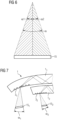
- FIG. 6 The division of the field angle range into two field angle ranges is shown in Figure 6 shown schematically.
- the figure shows a display 15 and the field angle ⁇ under which the display 15 is viewed.
- This field angle is divided into two field angles ⁇ 1 and ⁇ 2, which do not overlap in the present example.
- the partial field angles ⁇ 1 , ⁇ 2 can be selected in such a way that they each represent the largest field angle of a light guide, as shown in Figure 2 To cover the entire field angle range given by the field angle ⁇ , Then two light guides are connected as shown in Figure 2 and which are referred to below as sub-light guides 1 1 , 1 2 of the light guide 1, are arranged one behind the other.
- FIG. 7 shows in a section along a meridian the two sub-light guides 1 1 and 1 2 arranged one behind the other with the coupling structures 3 1 and 3 2 .
- Each of the coupling structures 3 1 , 3 2 is assigned its own display 15 1 , 15 2 , which each show the image area that can be perceived under the corresponding field angle range ⁇ 1, ⁇ 2.
- the field angles ⁇ 1 , ⁇ 2 are selected such that the field angle ranges covered by them can be completely transmitted by the respective light guide 1 1 , 1 2 .
- the partial field angles ⁇ 1 , ⁇ 2 can be, for example, 20°, with the partial field angle ⁇ 1 covering a field angle range from -20° to 0° and the partial field angle ⁇ 2 covering a field angle range from 0° to +20°. Since the sub-light guides 1 1 , 1 2 arranged one behind the other transmit the complete image together, they together form the light guide 1.
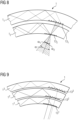
- the coupling out of the light guide 1, which is constructed from sub-light guides 1 1 , 1 2, is in Figure 8 shown schematically.
- Each of the sub-light guides 1 1 , 1 2 has an output coupling structure 13 1 , 13 2 which essentially corresponds to the output coupling structure 13 of Figure 2
- the structures of the base gratings 5, on which the diffraction lens is superimposed are selected so that the light guided through the sub-light guides 1 1 , 1 2 is coupled out at the correct angles.
- the coupling structures 3 1 , 3 2 are adapted accordingly to the base gratings of the coupling-out structures 13 1 , 1 3 2.
- a sufficiently large field of view can be realized.
- diffractive coupling and decoupling structures can be manufactured very flat, and a larger number of sub-light guides can also be arranged one behind the other.
- the light guide with sub-light guides, each of which is designed to transmit a different wavelength range of visible light.
- one sub-light guide with its input coupling structure and its output coupling structure can be designed to transmit red light
- another sub-light guide with its input coupling structure and its output coupling structure can be designed to transmit green light
- a third sub-light guide with its input coupling structure and its output coupling structure can be designed to transmit blue light. In this way, a complete color image can be transmitted by means of three sub-light guides.
- FIG. 9 shows a light guide 1 with three sub-light guides 1 1 , 1 2 , 1 3 and the associated coupling-out structures 13 1 , 13 2 , 13 3.
- Each sub-light guide 1 1 , 1 2 , 1 3 with its associated coupling-in structure (not shown) and its coupling-out structure 13 1 , 13 2 , 13 3 is designed to transmit a color, for example the first sub-light guide 1 1 to transmit red light, the second sub-light guide 1 2 to transmit green light and the third sub-light guide 1 3 to transmit blue light.
- a color image can therefore be transmitted with the three sub-light guides 1 1 , 1 2 , 1 3 .
- each field angle range is to represent a color image
- three substructures 1 1 , 1 2 , 1 3 for red, green and blue light are required for each field angle range defined by a partial field angle ⁇ 1, ⁇ 2.
- there are six sub-light guides in the above example three each for the field angle range defined by the partial field angle ⁇ 1 and three each for the field angle range defined by the partial field angle ⁇ 2.
- the Sub-light guides with diffractive coupling and diffractive coupling can be manufactured quite thin, so that a light guide 1 with six substructures can be manufactured without problems with an acceptable total thickness.
- the in Figure 4 The diffraction lens 11 shown is not color corrected. This is because the angles at which constructive interference occurs depend on the wavelength of the light. The lack of color correction leads to a longitudinal color error and a transverse color error.
- the longitudinal chromatic aberration results from the fact that the angles for the first diffraction maximum differ from one another, so that the lens has different focal lengths for different wavelengths.
- the diffraction lens is designed, for example, so that its focal length for green light corresponds to the radius of curvature of the light guide, the focal length for red light is somewhat smaller and the focal length for blue light is somewhat larger than the radius of curvature of the light guide 1, so that a certain image blurring occurs in the red and blue parts of the image when the green part of the image is sharp.
- the loss of sharpness due to the blurring in the red and blue image components is approximately 0.6 dpt, assuming a radius of curvature of the light guide 1 and a focal length of the diffraction lens 11 of 150 mm each. A loss of sharpness of 0.6 dpt can still be considered acceptable.
- the lateral chromatic aberration is based on the different magnification resulting from the different focal lengths and thus the different image scale of the individual colors in the respective focal plane. While the lateral chromatic aberration does not appear on the optical axis, it increases with distance from the optical axis. If the exit pupil of the diffraction lens is 20 mm behind the coupling structure, lateral chromatic aberrations occur at the edge of an image field of ⁇ 12°, which are on the order of around 10 arc minutes at the edge of the field. Such lateral chromatic aberrations are no longer acceptable and must be corrected.
- One way of correcting the lateral chromatic aberration is to place a correction element in front of the coupling structure 3 of the light guide 1 in an imaging device comprising the light guide 1, which correction element generates a lateral chromatic aberration that is inverse to the lateral chromatic aberration induced by the diffraction lens 11, so that the lateral chromatic aberration of the diffraction lens 11 and the lateral chromatic aberration of the correction element just cancel each other out.
- An example of such a correction element is shown in Figure 10 shown.
- the figure shows a schematic representation of an HMD with an image generator 15 on which an output image is displayed, which is to be converted into a virtual image by an imaging optics.
- this imaging optics comprises a correction element 17 for correcting the lateral chromatic aberration.
- this correction element 17 comprises a classic refractive optical element 19 and a diffractive optical element 21. These two are coordinated with one another in such a way that together they induce a lateral chromatic aberration which compensates for the lateral chromatic aberration of the diffractive lens 11 of the output structure 13.
- the refractive optical element 19 and the diffractive optical element 21 can be shifted relative to one another, which also allows a dynamic lateral chromatic aberration to be compensated.
- a dynamic lateral chromatic aberration is caused by the user's eye movement, which causes lateral chromatic aberrations occurring in the field along edges to change their extent.
- an eye tracker 23 is provided in the present embodiment to determine the direction of view.
- a control unit 25 controls the relative displacement between the refractive optical element 19 and the diffractive element 21 of the correction element 17. If the dynamic lateral chromatic aberration is not to be compensated, it is possible to arrange the refractive optical element 19 and the diffractive optical element 21 fixed relative to one another and to dispense with the eye tracker 23 and the control unit 25.
- the correction element 17 also makes it possible to compensate for the previously mentioned pupil distortion, which occurs due to the guidance of the light rays along the meridians, by suitable design of the refractive optical element 19 and/or the diffractive optical element 21.
- Figure 11 shows an imaging optics for an HMD with a light guide 1 according to the invention and a correction element that only serves to compensate for pupil distortion.
- a parabolic mirror 27 with a radius of curvature of 480 mm is used as the correction element.
- the radius of curvature of the light guide 1 and the focal length of the diffraction lens of the coupling-out structure 13 are again assumed to be 150 mm.
- the starting point of the Figure 10 The beam of rays striking the parabolic mirror 27 from the left is located outside the image at the focal point of the parabolic mirror. Linear astigmatism can also be reduced by creating a quadratic pupil distortion in the longitudinal direction in an analogous manner.
- pupil distortion can also be corrected using other off-axis elements. Correcting pupil distortion also makes longer transmission lengths in the light guide possible.
- the display 15 it is possible to arrange the display 15 closer to the coupling structure if a polarization beam splitter 29 and a delay plate 32 in the form of a ⁇ /4 plate are arranged in front of the coupling structure, as shown in Figure 12
- the coupling with the aid of a polarization beam splitter and a delay plate is shown, for example, in WO 2008/023367 A1 , in particular with reference to Figure 3 , described.
- WO 2008/023367 A1 reference is made to the coupling using a polarization beam splitter and a retardation plate.
- the present invention has been described in detail using exemplary embodiments for explanatory purposes. However, it will be apparent to a person skilled in the art that deviations from the exemplary embodiments can be made within the scope of the invention.
- the number of partial field angles can be greater than two and the number of color channels to be transmitted can be smaller or greater than three.
- a refractive lens such as a Fresnel lens
- the scattering effect can be superimposed on the coupling-in structure instead of being superimposed on the output structure.
- coupling-in and coupling-out structures can be used, for example reflective structures such as partially transparent mirrors instead of diffractive structures, or the diffractive structures described can be replaced by blaze gratings. In the latter case, it is possible to optimize the diffraction structure to a specific diffraction order by selecting the blaze angle appropriately.
- the diffraction lens can also be implemented as a blaze grating. Dichroic partially transparent mirrors can then be used, for example, to couple out a specific wavelength range.
- the coupling-out structures are arranged in the rear surface of the light guide, they can also be arranged in the front surface, so that the light first passes through the rear surface approximately vertically, for example, and only then onto the deflecting/diffractive structure on the front surface. Accordingly, after passing through the light guide, the light can be deflected by a deflecting/diffractive structure on the front surface in the direction of the rear surface, through which it then exits the light guide approximately vertically, for example.
- the invention should therefore not be limited by the described embodiments, but only by the appended claims.
Landscapes
- Physics & Mathematics (AREA)
- General Physics & Mathematics (AREA)
- Optics & Photonics (AREA)
- Optical Couplings Of Light Guides (AREA)
Description
- Die vorliegende Erfindung betrifft einen gekrümmten Lichtleiter für ein HMD (Head Mounted Display), also für eine am Kopf zu tragende Anzeigevorrichtung. Daneben betrifft die Erfindung eine Abbildungsoptik für ein HMD sowie das HMD selbst.
- Ein HMD ist ein Anzeigesystem, bei dem ein Ausgangsbild mit Hilfe einer Abbildungsoptik in das Blickfeld des Trägers des HMD abgebildet wird. Häufig ist es dabei wünschenswert, neben dem bereit gestellten Bild auch einen ungestörten Blick auf die Umgebung zuzulassen. Diese Anordnung verhindert Lösungen, bei denen ein intransparenter Bildgeber und eine dazugehörige Abbildungsoptik direkt vor dem Auge angeordnet werden. In einer Klasse von HMDs, die gelegentlich auch Datenbrillen genannt werden, werden daher die Ausgangsbilder üblicherweise außerhalb des Sichtbereichs des Auges generiert, und das erzeugte Ausgangsbild wird mit Hilfe einer Abbildungsoptik in der gewünschten Blickrichtung vor das Auge eingespiegelt. Hierzu umfasst das HMD beispielsweise einen Lichtleiter, über den der Abbildungsstrahlengang zum Generieren des virtuellen Bildes durch innere Reflektion von einer außerhalb des Sichtfeldes gelegenen Einkoppelstruktur zu einer im Sichtfeld des Auges gelegenen zumindest teilweise transparenten Auskoppelstruktur geleitet wird. Das Ein- und Auskoppeln kann dabei mittels refraktiver Strukturen, mittels reflektiver Strukturen oder mittels diffraktiver Strukturen erfolgen. Diffraktive Ein- und Auskoppelstrukturen sind beispielsweise in
DE 10 2015 122 055 A1 , inUS 2006/012181 A1 und inUS 2010/0220295 A1 beschrieben. Beispiele für reflektive oder refraktive Ein- oder Auskoppelstrukturen sind beispielsweise inUS 2012/00002294 A1 DE 10 2011 007 812 , inWO 2015/075206 A1 undWO 2015/075207A1 A1 beschrieben. - Um eine große Ausgangspupille zu erzielen, schlägt die
US 8,320,032 B2 eine Mehrfachauskopplung vor. Während dieUS 8,320,032 B2 einen planaren Lichtleiter beschreibt, wird in derUS 8,830,584 B2 das Prinzip der Mehrfachauskopplung auf sphärische Lichtleiter übertragen. Für eine ideale Mehrfachauskopplung müssen im Falle eines sphärisch-konzentrischen Lichtleiters die Auskopplungsstrukturen parallel zu den Breitenkreisen auf der Sphäre liegen. Damit kann Licht von der Einkoppelstruktur auf die Auskoppelstruktur übertragen und dort mehrfach ausgekoppelt werden. So lässt sich eine ideale Punkt-zu-Punkt-Abbildung im Zentrum der Sphäre realisieren. Eine Mehrfachauskopplung ist darüber hinaus auch inDE 10 2015 122 055 A1 beschrieben. - In
US 2013/0088780 A1 wird das Prinzip der Punkt-zu-Punkt-Abbildung dazu verwendet, mittels mehrerer Lichtleiter verschiedene Fokusebenen zu realisieren. Dabei müssen jedoch die Lichtleiter vom Auge weg gekrümmt sein, so dass die Lichtleiter vom Auge aus gesehen eine konvexe Krümmung aufweisen. Aus ästhetischen Gründen sollten die Lichtleiter vom Auge aus gesehen jedoch eine konkave Krümmung aufweisen, so dass das Head Mounted Display die Form einer gewöhnlichen Brille annehmen kann. - In
US 8,842,368 B2 ist zudem ein Head Mounted Display mit diffraktiver Ein- und Auskopplung beschrieben, in dem gekrümmte diffraktive Strukturen verwendet werden, um eine Pupillenabbildung zu generieren. Mit einer Mehrfachauskopplung wäre diese Pupillenabbildung jedoch nicht verträglich. - In
US 2012/0300311 A1 ist ein Head-Mounted Display mit einem zylindrisch gekrümmten Lichtleiter und diffraktiver Ein- und Auskopplung beschrieben. Um zu erreichen, dass ein in den Lichtleiter eingekoppeltes kollimiertes Bild als ein kollimiertes Bild mit einer vergrößerten Austrittspupille ausgekoppelt werden kann, weisen das Einkoppelgitter und das Auskoppelgitter in Krümmungsrichtung des Lichtleiters variable Gitterabstände auf. - In der
DE 10 2012 213 685 A1 ist eine Anzeigevorrichtung beschrieben, in der in einen gekrümmten Lichtleiter eingekoppelte Strahlenbündel vor dem Einkoppeln mittels einer zwischen dem Bildgeber und dem Lichtleiter angeordneten Zusatzoptik in kollimierte Strahlenbündel umgewandelt werden und als kollimierte Strahlenbündel aus dem Lichtleiter ausgekoppelt werden. Das Kollimieren kann statt von der Zusatzoptik 9 von dem zur Einkopplung verwendeten Einkoppelgitter übernommen werden. - Die
DE 10 2015 122 055 A1 beschreibt eine Anzeigevorrichtung, die eine Korrekturanordnung zum Korrigieren von Abbildungsfehlern umfasst. - Die
DE 10 2008 009 095 A1 beschreibt ein Durchlicht-Display-System, in dem ein Bild durch eine Scheibe sichtbar ist, in die ein von einem Bildgeber auf einer Streuscheibe erzeugtes Zwischenbild mittels einer Abbildungslinse eingekoppelt wird. Zwischen der Streuscheibe und der Abbildungslinse ist eine Korrekturlinse angeordnet, mit deren Hilfe die Bildqualität optimiert werden soll. - Die
DE 602 05 722 T2 beschreibt ein Relais-Linsensystem, das ein durch eine Bildquelle erzeugtes Bild auf ein vor einem Auge zu tragendes gekrümmtes Visier projiziert, von wo das vom Relais-Linsensystems kommende Licht in Richtung auf das Auge reflektiert wird. Das Relais-Linsensystem beinhaltet ein optisches Element, welches eine chromatische Korrektur durchführt. - Die
WO 2008/023367 A1 beschreibt ein Einkopplungsmodul zum Einkoppeln eines Strahlengangs in einen Lichtleiter. Das Einkopplungsmodul umfasst einen Polarisationsstrahlteiler und eine Verzögerungsplatte. - In
US 2012/0300311 A1 ist ein Head-Mounted Display mit einem zylindrisch gekrümmten Lichtleiter beschrieben. Eine durch die Krümmung verursachte optische Wirkung des gekrümmten Lichtleiters wird mithilfe der Einkoppelstruktur und der Auskoppelstruktur ausgeglichen. Mit diesem Lichtleiter wird erreicht, dass ein in den Lichtleiter eingebrachtes kollimiertes Bild auch wieder als kollimiertes Bild mit einer vergrößerten Ausgangspupille aus dem Lichtleiter ausgekoppelt wird. - Die
DE 10 2015 116 297 A1 beschreibt eine Abbildungsoptik mit einem Brillenglas und einem Optikelement, das auch als abbildender Lichtleiter bezeichnet wird, über welches ein Lichtstrahl in das Brillenglas eingekoppelt wird. Das Brillenglas kann eine sphärische Krümmung aufweisen. - Gegenüber dem genannten Stand der Technik ist es eine erste Aufgabe der vorliegenden Erfindung, einen vorteilhaften Lichtleiter für ein HMD zur Verfügung zu stellen, der bei vom Auge aus gesehen konkav gekrümmtem Lichtleiter das Generieren eines virtuellen Bildes im unendlichen oder in einer festgelegten Distanz vor dem Auge ermöglicht. Eine weitere Aufgabe der vorliegenden Erfindung ist es, eine vorteilhafte Abbildungsoptik für eine HMD zur Verfügung zu stellen mit der das Generieren eines virtuellen Bildes im unendlichen oder in einer festgelegten Bildebene vor dem Auge bei Verwendung eines vom Auge aus gesehen sphärisch-konkav gekrümmten Lichtleiters möglich ist.
- Eine dritte Aufgabe der vorliegenden Erfindung ist es, ein HMD zur Verfügung zu stellen, welches einen vom Auge aus gesehen sphärisch-konkav gekrümmten Lichtleiter aufweist und das in der Lage ist, ein virtuelles Bild im unendlichen oder einer festgelegten Bildebene vor dem Auge zu generieren.
- Die erste Aufgabe wird durch einen gekrümmten Lichtleiter nach Anspruch 1 gelöst, die zweite Aufgabe durch eine Abbildungsoptik nach Anspruch 10 und die dritte Aufgabe durch ein HMD nach Anspruch 15.
- Die abhängigen Ansprüche enthalten vorteilhafte Ausgestaltungen der Erfindung.
- Ein erfindungsgemäßer gekrümmter Lichtleiter für ein HMD ist bei bestimmungsgemäßem Gebrauch vor wenigstens einem Auge angeordnet und weist vom Auge aus gesehen eine sphärisch-konkave Krümmung auf. Er umfasst eine zum Auge weisende Rückfläche sowie eine vom Auge weg weisende Vorderfläche. Außerdem umfasst er eine Einkoppelstruktur zum Einkoppeln von Licht in den Lichtleiter derart, dass Licht unter Reflektion an der Vorderfläche und/oder an der Rückfläche durch den Lichtleiter geleitet wird, und eine Auskoppelstruktur zum Auskoppeln des durch den Lichtleiter geleiteten Lichts. Ein solcher Lichtleiter übt auf das eingekoppelte Licht eine sammelnde Wirkung aus. Erfindungsgemäß weist der Lichtleiter daher eine zerstreuende Struktur auf, deren Brennweite betragsmäßig kleiner oder gleich dem Krümmungsradius des Lichtleiters ist. Die zerstreuende Struktur kann der Auskoppelstruktur oder der Einkoppelstruktur überlagert sein, so dass kein zusätzliches optisches Element in den Lichtleiter integriert werden muss. Es besteht aber auch die Möglichkeit, die Brennweite der zerstreuenden Struktur auf zwei Unterstrukturen aufzuteilen und die eine Unterstruktur der Einkoppelstruktur und die andere Unterstruktur der Auskoppelstruktur zu überlagern.
- Durch die Integration einer zerstreuenden Struktur in den Lichtleiter wird es möglich, den Lichtleiter zum Generieren eines virtuellen Bildes, welches sich vom Auge aus gesehen jenseits des Lichtleiters befindet, zu nutzen. Wenn dabei die Brennweite der zerstreuenden Struktur betragsmäßig gleich dem Krümmungsradius des Lichtleiters ist, befindet sich das Bild im unendlichen, wenn die Brennweite der zerstreuenden Struktur betragsmäßig kleiner als der Krümmungsradius des Lichtleiters ist, also die zerstreuende Wirkung der zerstreuenden Struktur größer als die sammelnde Wirkung des Lichtleiters ist, befindet sich das virtuelle Bild in einem Abstand vom Auge, welcher sich nach der Stärke der zerstreuenden Wirkung, d.h. nach der Brennweite der zerstreuenden Struktur bestimmt.
- Die zerstreuende Struktur kann insbesondere eine Beugungslinse, bspw. in Form eines Volumenhologramms oder eines Blazegitters, sein. Die zerstreuende Wirkung der Beugungslinse wird durch ihre Brennweite bestimmt. Um eine virtuelles Bild im Unendlichen zu generieren findet dabei eine Beugungslinse Verwendung, deren Brennweite betragsmäßig gleich dem Krümmungsradius des Lichtleiters ist. Dies gilt insbesondere dann, wenn im Lichtleiter die Krümmungsmittelpunkte der Vorderfläche und der Rückfläche zusammenfallen. Fallen die Krümmungsmittelpunkte der Vorderfläche und der Rückfläche nicht zusammen oder weist der Lichtleiter eine nicht von der beanspruchten Erfindung gedeckte von der sphärischen Krümmung abweichende Krümmung auf, beispielsweise weil er im Rahmen einer Datenbrille gleichzeitig zur Korrektur einer Fehlsichtigkeit herangezogen werden soll, gilt diese Beziehung lediglich näherungsweise. Die genaue Brennweite der Beugungslinse zum Generieren eines virtuellen Bildes ist dann abhängige von der konkreten Krümmung des Lichtleiters und kann ggf. näherungsweise oder experimentell bestimmt werden. Beispielsweise kann die Brennweite der Beugungslinse kleiner oder gleich dem kleineren der beiden Krümmungsradien der Vorderfläche und der Rückfläche des Lichtleiters sein, wenn die Krümmungsmittelpunkte der Vorderfläche und der Rückfläche nicht zusammenfallen. In diesem Fall befindet sich das virtuelle Bild ggf. nicht im Unendlichen, jedoch in einem großen Abstand vom Lichtleiter, so dass es sich als näherungsweise im Unendlichen befindend angesehen werden kann. Im Falle einer experimentellen Bestimmung kann bspw. derjenige Punkt ermittelt werden, bei dem ein von einer Punktlichtquelle ausgehendes divergentes Strahlenbündel vom Lichtleiter ohne die zerstreuende Struktur ins Unendliche abgebildet wird und der Abstand dieses Punktes von der Rückfläche des Lichtleiters als dessen Krümmungsradius angesehen werden.
- Eine Beugungslinse fokussiert das Licht in den Brennpunkt mittels Interferenz, wobei im Brennpunkt eine konstruktive Interferenz und außerhalb des Brennpunkts eine destruktive Interferenz vorliegt. Typischerweise wird der Brennpunkt von dem bei der Beugung auftretenden ersten Beugungsmaximum gebildet. Zum Herbeiführen der entsprechenden Beugung kann die Beugungslinse entweder sich abwechselnde transparente und intransparente Zonen aufweisen oder sich abwechselnde Zonen mit einer kürzeren und einer längeren optischen Weglänge für das für die Beugungslinse passierende Licht. Die Abstände und die Breite der Zonen der Beugungslinse richten sich dabei nach der Wellenlänge des Lichtes und der gewünschten Brennweite der Beugungslinse. Im Falle sich abwechselnder transparenter und intransparenter Zonen wird die Beugung dadurch erzeugt, dass nur bestimmte Teile der Wellenfront die Beugungslinse passieren können, wobei die passierenden Teile in bestimmten Richtungen konstruktiv miteinander interferieren und in anderen Richtungen destruktiv miteinander interferieren. Im Falle von Zonen mit unterschiedlichen optischen Weglängen erfolgt beim Durchgang der Wellenfront durch die unterschiedlichen Zonen der Beugungslinse eine Phasenverschiebung zwischen den die unterschiedlichen Zonen passierenden Teilen der Wellenfront. Diese Phasenverschiebung führt dazu, dass die unterschiedlichen Teile der Wellenfront in bestimmten Richtungen konstruktiv miteinander interferieren und in anderen Richtungen destruktiv miteinander interferieren. Die Ausgestaltung der Beugungslinse mit transparenten und intransparenten Zonen bietet die Möglichkeit, die Beugungslinse mit relativ einfachen Mitteln herzustellen. Die Herstellung einer Beugungslinse mit Zonen unterschiedlicher optischer Weglängen bietet dagegen den Vorteil, dass sie bei einer Augmented Reality-Anwendung keinen Einfluss auf das von außen durch den Lichtleiter hindurchtretende Umgebungslicht ausübt und somit die Wahrnehmung der Umgebung nicht schwächt.
- Die zerstreuende Struktur führt jedoch zu einem Farblängsfehler und einem Farbquerfehler. Ein Farblängsfehler bedeutet, dass die Brennpunkte von Licht unterschiedlicher Farben (Wellenlängen) in unterschiedlichen Abständen zur zerstreuenden Struktur liegen, so dass in einen bestimmten Brennpunkt nur Licht einer Farbe fokussiert ist, während das Licht anderer Farben in diesem Brennpunkt einen leichten Defokus aufweist. Ein Farbquerfehler ist dagegen die Folge unterschiedlicher Abbildungsmaßstäbe der zerstreuenden Struktur für Licht unterschiedlicher Farben (Wellenlängen) des durch den Lichtleiter geleiteten Lichtes, was zu farbigen Rändern in der Abbildung führt. Während der Farblängsfehler in der Regel klein genug ist, um auf eine Korrektur verzichten zu können, kann der Farbquerfehler am Feldrand des Bildfeldes so groß werden, dass er als störend wahrgenommen wird. Um den durch die zerstreuende Struktur induzierten Farbquerfehler zu minimieren, ist es daher vorteilhaft, wenn die zerstreuende Wirkung der zerstreuenden Struktur auf die Mitte des Bildfeldes zentriert ist.
- Durch den Lichtleiter kann jeweils nur ein bestimmtes Winkelspektrum des Strahlengangs übertragen werden. Je kleiner das Winkelspektrum ist, desto kleiner ist das durch den Lichtleiter übertragbare Bildfeld. Um für ein großes Bildfeld ein großes Winkelspektrum übertragen zu können, besteht die Möglichkeit, dass die Einkoppelstruktur sowie die Auskoppelstruktur jeweils mehrere Unterstrukturen umfassen, welche unterschiedliche Teile des Winkelspektrums des Lichtes in den Lichtleiter einkoppeln bzw. aus dem Lichtleiter auskoppeln. Diese unterschiedlichen Teile des Winkelspektrums können dann so ausgelegt sein, dass sie jeweils dem Maximum des von dem Lichtleiter übertragbaren Winkelspektrums entsprechen. Das gesamte Winkelspektrum des übertragenen Lichtes ergibt sich dann aus der Zusammensetzung der beiden Teile, so dass insgesamt ein großes Winkelspektrum übertragen werden kann, so dass ein großes Bildfeld generierbar ist.
- Darüber hinaus sind diffraktive Ein- und Auskoppelstrukturen jeweils für eine bestimmte Längenwelle optimiert. Mit zunehmender Abweichung von dieser optimierten Wellenlänge entsteht keine für die Auskopplung nutzbare Interferenz mehr. Das mittels der Ein- und Auskoppelstrukturen ein- bzw. ein auszukoppelnde Wellenlängenspektrum des Lichtes ist daher begrenzt. Wenn ein Bild mit einem breiten Wellenlängenspektrum, idealer Weise ein Farbbild, generiert werden soll, ist es daher vorteilhaft, wenn die Auskoppelstruktur jeweils mehrere Unterstrukturen umfasst, welche unterschiedliche Teile des Spektralbereiches des in den Lichtleiter einzukoppelnden Lichtes in den Lichtleiter einkoppeln bzw. aus dem Lichtleiter auskoppeln. Um ein Farbbild generieren zu können, sind daher in einer besonderen Ausgestaltung des erfindungsgemäßen Lichtleiters eine Einkoppelstruktur und eine Auskoppelstruktur vorhanden, die jeweils drei Unterstrukturen umfasst, wovon beispielsweise eine für blaues Licht, eine für grünes Licht und eine weitere für rotes Licht optimiert ist. Wenn dann noch das Winkelspektrum in mehrere Teile aufgeteilt wird, müssen diese Unterstrukturen jeweils mehrfach vorhanden sein, nämlich jeweils einmal für jeden Teil des Winkelspektrums. Insgesamt ergeben sich somit im Falle eines in zwei Teile aufgeteilten Winkelspektrums und drei Farben sechs Unterstrukturen. Soll das Winkelspektrum in n Teile aufgeteilt werden, ergeben sich entsprechend 3n Unterstrukturen für die Einkoppelstruktur und 3n Unterstrukturen für die Auskoppelstruktur. Dabei besteht die Möglichkeit, die unterschiedlichen Spektralbereiche und/oder die unterschiedlichen Teile des Winkelspektrums durch einen gemeinsamen Lichtleiter zu leiten, oder den Lichtleiter in mehrere Unterlichtleiter aufzuteilen, die unterschiedliche spektrale Wellenlängenbereiche und/oder unterschiedliche Teile des Winkelspektrums leiten. Diese Unterlichtleiter können dabei als getrennte Übertragungskanäle angesehen werden. Das Vorhandensein unterschiedlicher Übertragungskanäle ermöglicht es, ein Übersprechen der übertragenen Signale zuverlässig zu vermeiden. Das Übertragen mehrerer Spektralbereiche und/oder Teile des Winkelspektrums durch einen gemeinsamen Lichtleiter reduziert dagegen die Komplexität des Lichtleiters und vereinfacht dadurch seine Herstellung.
- Die Einkopplung der Lichtstrahlen in den Lichtleiter erfolgt derart, dass die eingekoppelte Lichtstrahlen entlang von Großkreisen verlaufen, die auf der sphärischen Vorderfläche und/oder der sphärischen Rückfläche des Lichtleiters durch diejenigen Punkte verläuft, die in Kugelkoordinaten durch die Polarwinkel 0° und 180° gegeben sind. Diese Punkte sind in der Regel selbst nicht Teil der sphärischen Vorderfläche und/oder der sphärischen Rückfläche des Lichtleiters, da diese nur einen Ausschnitt einer diese Punkte enthaltenden gedachten Kugeloberfläche darstellen. Auf der Erdoberfläche entsprechen derartige Großkreise den Längenkreisen. Die Großkreise werden daher im Folgenden als Längenkreise des Lichtleiters bezeichnet. Auf diese Weise existiert für alle Längenkreise, entlang derer die eingekoppelten Lichtstrahlen verlaufen, ein alle diese Längenkreise im rechten Winkel schneidender Großkreis, also ein Großkreis, der von den Lichtstrahlen im rechten Winkel passiert wird oder passiert würde, falls die Lichtstrahlen bereits vor dem Erreichen dieses Großkreises ausgekoppelt werden. Der die Längenkreise im rechten Winkel schneidende Großkreis verläuft damit im Wesentlichen parallel zu den Strukturelementen der Einkoppelstruktur und der Auskoppelstruktur, d.h. parallel zu den Gitterstrukturen im Falle einer diffraktiven Ein- und Auskopplung bzw. parallel zu den Grenzlinien zwischen Fresnel-Strukturen im Falle einer reflektiven oder refraktiven Ein- und Auskopplung. Auf der Erdoberfläche würde der schneidende Großkreis dem Äquator entsprechen. Der die Längenkreise im rechten Winkel schneidende Großkreis wird daher im Folgenden Äquator des Lichtleiters genannt. Dabei ist es besonders vorteilhaft, wenn die zerstreuende Struktur in die Auskoppelstruktur integriert ist, da dann der Verlauf der Lichtstrahlen entlang von Längenkreisen innerhalb des Lichtleiters durch die zerstreuende Wirkung der zerstreuenden Struktur nicht beeinflusst wird. Der Verlauf der Lichtstrahlen entlang von Längenkreisen innerhalb des Lichtleiters eröffnet die Möglichkeit, die Auskopplungsstruktur erfindungsgemäß näher als die Einkoppelstruktur am Äquator des Lichtleiters anzuordnen. Dabei kann es vorteilhaft sein wenn, die Auskoppelstruktur nicht weiter als 5 Grad, vorzugsweise nicht weiter als 3 Grad vom Äquator des Lichtleiters angeordnet ist. Insbesondere kann die Auskopplungsstruktur dabei so angeordnet sein, dass der Äquator des Lichtleiters auch die Auskoppelstruktur schneidet, insbesondere so, dass der Äquator auch die Auskoppelstruktur symmetrisch schneidet. Durch die Nähe der Auskopplungsstruktur zum Äquator des Lichtleiters schneiden die Längenkreise, entlang derer sich die Lichtstrahlen ausbreiten, die Strukturelemente der Auskoppelstruktur nahezu im rechten Winkel, so dass die Lichtstrahlen nahezu im rechten Winkel auf die Strukturelemente der Auskoppelstruktur auftreffen. Dadurch können Unterschiede in der Pupillenform, die auf eine unterschiedliche Anzahl an Reflektionen innerhalb des Lichtleiters zurückzuführen sind minimiert werden. Unterschiedliche Anzahlen der Reflektionen innerhalb des Lichtleiters können dazu führen, dass die Beugungslinse an verschiedenen Orten genutzt wird, was zu einer Pupillenverzerrung führen kann, die ggf. korrigiert werden muss. Mit der äquatornahen Anordnung der Auskoppelstruktur kann die Pupillenverzerung verringert und ggf. minimiert werden.
- Erfindungsgemäß wird außerdem eine Abbildungsoptik mit einem Abbildungsstrahlengang, einem Lichtleiter und wenigstens einem bildformenden optischen Element zur Verfügung gestellt. Die erfindungsgemäße Abbildungsoptik zeichnet sich dadurch aus, dass sie einen erfindungsgemäßen Lichtleiter umfasst, wobei der Lichtleiter als das wenigstens eine bildformende optische Element dient. Die Abbildungsoptik kann dabei insbesondere auch ausschließlich aus dem erfindungsgemäßen Lichtleiter bestehen. Dadurch, dass der Lichtleiter gleichzeitig als bildformendes optisches Element fungiert, wird es möglich, eine kompakte Abbildungsoptik herzustellen. Der erfindungsgemäße Lichtleiter ermöglicht es dabei, bei einer vom Auge aus gesehen konkaven Krümmung des Lichtleiters, insbesondere einer sphärische-konkaven Krümmung des Lichtleiters, ein virtuelles Bild bereit zu stellen, welches sich vom Auge aus gesehen in einem endlichen oder unendlichen Abstand jenseits des Lichtleiters befindet.
- In einer Weiterbildung der erfindungsgemäßen Abbildungsoptik ist der Einkoppelstruktur des Lichtleiters im Abbildungsstrahlengang ein Korrekturelement zum Vorabkorrigieren einer vom Lichtleiter induzierten trapezförmigen Pupillenverzeichnung vorgelagert. Dieses Korrekturelement generiert eine zur vom Lichtleiter induzierten Pupillenverzeichnung inverse Pupillenverzeichnung. Die beiden Pupillenverzeichnungen kompensieren sich dann gegenseitig. Zusätzlich oder alternativ kann der Einkoppelstruktur des Lichtleiters im Abbildungsstrahlengang eine einen statischen Farbquerfehler kompensierende Kompensationsoptik vorgelagert sein. Der statische Farbquerfehler wird von dem die zerstreuende Struktur enthaltenden Lichtleiter induziert und ist von der Augenbewegung unabhängig. Er kann daher mit einer optischen Kompensationsoptik ohne weiteres kompensiert werden. Diese Kompensationsoptik induziert einen den vom Lichtleiter induzierten Farbquerfehler inversen Farbquerfehler, so dass sich die beiden Farbquerfehler aufheben. Wenn der Einkoppelstruktur des Lichtleiters im Abbildungsstrahlengang ein Manipulator vorgelagert ist, der ein diffraktives optisches Element und ein refraktives optisches Element umfasst, die senkrecht zur optischen Achse des Abbildungsstrahlengangs relativ zueinander verschiebbar angeordnet sind, und außerdem ein Eye-Tracker zum Erfassen der Blickrichtung des Auges vorhanden ist, ist es zudem möglich, einen dynamischen, feldkonstanten Farbquerfehler, der vom Lichtleiter herbeigefügt wird, vorab zu korrigieren. Ein dynamischer Farbquerfehler kommt durch Augenbewegungen zustande, zumindest dann, wenn die chromatische Bandbreite des übertragenen Lichtes eine gewisse Schwelle überschreitet.
- Außerdem können der Einkoppelstruktur des Lichtleiters im Abbildungsstrahlengang ein Polarisationsstrahlenteiler und eine Verzögerungsplatte vorgelagert sein. Polarisationsstrahlteiler in Verbindung mit der Verzögerungsplatte ermöglicht die Einkopplung des Abbildungsstrahlengangs durch die Einkoppelstruktur bei gleichzeitig kompakten Abmessungen der Abbildungsoptik.
- Gemäß einem weiteren Aspekt der Erfindung wird ein HMD mit einem Display zum Darstellen eines Ausgangsbildes und einer erfindungsgemäßen Abbildungsoptik zum Generieren eines virtuellen Bildes von dem Ausgangsbild zur Verfügung gestellt. Da die erfindungsgemäße Abbildungsoptik wegen der Verwendung des Lichtleiters als einem bildformenden optischen Element kompakt ausgebildet sein kann, ist es möglich, durch die Verwendung der erfindungsgemäßen Abbildungsoptik auch ein kompaktes HMD zur Verfügung zu stellen, welches es ermöglicht, bei einem vom Auge aus gesehen konkav gekrümmten Lichtleiter ein virtuelles Bild zu generieren, welches sich vom Auge aus gesehen jenseits des Lichtleiters im Unendlichen oder in einem bestimmten Abstand vom Lichtleiter befindet..
- Weitere Merkmale, Eigenschaften und Vorteile der vorliegenden Erfindung ergeben sich aus der nachfolgenden Beschreibung von Ausführungsbeispielen unter Bezugnahme der beiliegenden Figuren.
- Figur 1
- zeigt eine ideale Punkt-Zug-Punkt-Abbildung, wie sie mit einem sphärischen Lichtleiter zu erreichen ist, welche zum Verständnis der beanspruchten Erfindung nützlich ist.
- Figur 2
- zeigt einen gekrümmten Lichtleiter mit einer Abbildung nach unendlich.
- Figur 3
- zeigt ein Beispiel für eine diffraktive Auskopplungsstruktur zum Auskoppeln eines durch den Lichtleiter übertragenen Strahlenbündels.
- Figur 4
- zeigt eine Beugungslinse.
- Figur 5
- zeigt die aus einer Überlagerung der Auskopplungsstruktur aus
Figur 3 und der Beugungslinse ausFigur 4 resultierende Auskopplungsstruktur. - Figur 6
- ist eine Darstellung zum Veranschaulichen des Feldwinkels eines betrachteten Displays.
- Figur 7
- zeigt, wie der Feldwinkel aus
Figur 6 auf zwei unterschiedliche Lichtleiter aufgeteilt werden kann. - Figur 8
- zeigt das Auskoppeln der durch die Lichtleiter aus
Figur 7 übertragenen Strahlenbündel. - Figur 9
- zeigt einen Lichtleiter mit drei Unterstrukturen, von denen jede zum Auskoppeln eines anderen Spektralbereichs geeignet ist.
- Figur 10
- zeigt eine Ausführungsvariante einer Abbildungsoptik mit einem Wellenfrontmanipulator zum Korrigieren eines durch den Lichtleiter induzierten Farbquerfehlers.
- Figur 11
- zeigt eine Ausführungsvariante einer Abbildungsoptik mit einem der Einkoppelstruktur des Lichtleiters vorgelagerten Korrekturelement zum Korrigieren einer durch den Lichtleiter induzierten Pupillenverzeichnung.
- Figur 12
- zeigt ein Beispiel für eine kompakte Abbildungsoptik.
- Bevor nachfolgend mit Bezug auf
Figur 2 auf das der Erfindung zugrunde liegende Prinzip eingegangen wird, wird mit Bezug aufFigur 1 die Wirkung eines sphärischen Lichtleiters erläutert. - In
Figur 1 ist ein sphärischer Lichtleiter 1 gezeigt, der eine am Rand des Lichtleiters gelegene diffraktive Einkoppelstruktur 3 und eine im Zentrum des Lichtleiters gelegene diffraktive Auskoppelstruktur 5 aufweist. Die Verbindungslinie zwischen dem Zentrum der Einkoppelstruktur 3 und dem Zentrum der Auskoppelstruktur 5 erstreckt sich im Wesentlichen entlang eines Längenkreises 7 der Sphäre des Lichtleiters 1, also entlang eines Großkreises, der durch diejenigen Punkte einer Sphäre, von der der Lichtleiter einen Teil darstellt, die in Kugelkoordinaten durch die Polarwinkel 0° und 180° gegeben sind, verläuft. Die Auskoppelstruktur 5 befindet sich im vorliegenden Ausführungsbeispiel auf dem Äquator 9 dieser Sphäre, derart, dass sie vom Äquator 9 symmetrisch geschnitten wird. - Die diffraktive Einkoppelstruktur 3 und die diffraktive Auskoppelstruktur 5 sind jeweils durch Beugungsgitter mit einem bestimmten Gittervektor gebildet, deren Gitterlinien parallel zu Breitenkreisen, also parallel zum Äquator 9 verlaufen. Mittels des die diffraktive Einkoppelstruktur 3 bildenden Beugungsgitters wird ein vom Zentrum des Sphäre des Lichtleiters 1 ausgehendes divergentes Strahlenbündel 2 derart abgelenkt, dass die einzelnen Strahlen des Strahlenbündels im Lichtleiter 1 derart auf die im bestimmungsgemäßen Gebrauch des Lichtleiters in einem HMD vom Auge weg weisende Vorderfläche 4 des Lichtleiters 1 auftreffen, dass durch Totalreflektion in Richtung auf die im bestimmungsgemäßen Gebrauch des Lichtleiters in einem HMD zum Auge weisende Rückfläche 6 des Lichtleiters 1 reflektiert werden, wo sie wiederum durch Totalreflektion in Richtung auf die Vorderfläche 4 des Lichtleiters 1 reflektiert werden. Auf diese Weise werden die Strahlen des Strahlenbündels durch mehrfache Totalreflektion an der Vorderfläche 4 und der Rückfläche 6 des Lichtleiters 1 zur Auskoppelstruktur 5 geleitet, wo sie mittels des Beugungsgitters derart abgelenkt werden, dass sie aus der Rückfläche 6 des Lichtleiters 1 heraustreten. Das aus der Rückfläche 6 des Lichtleiters 1 heraustretende Strahlenbündel ist dabei ein derart konvergentes Strahlenbündel 8, dass seine Strahlen wieder auf das Zentrum der Sphäre des Lichtleiters 1 fokussiert werden. Der in
Figur 1 gezeigte Lichtleiter 1 mit der diffraktiven Einkoppelstruktur 3 und der diffraktiven Auskoppelstruktur 5 bildet somit eine im Zentrum der Sphäre des Lichtleiters 1 gelegenen Punkt ideal auf sich selbst ab. - Zur Verwendung als Teil einer Abbildungsoptik eines HMDs ist der Lichtleiter 1, wie er in
Figur 1 gezeigt ist, jedoch nur bedingt nützlich. In einem HMD ist es üblicherweise gewünscht, ein Bild im Unendlichen zu generieren, das der Nutzer des HMD mit entspanntem Auge betrachten kann, oder ein Bild, das sich in einem definierten Abstand vom Auge jenseits des Lichtleiters befindet, so dass der Nutzer den Eindruck hat, das Bild schwebe in einem bestimmten Abstand vor seinem Auge. Mit anderen Worten, eine den Lichtleiter umfassende Abbildungsoptik soll in der Lage sein, ein virtuelles Bild jenseits des Lichtleiters zu generieren. Zwar bestünde grundsätzlich die Möglichkeit, dass durch die Auskoppelstruktur 5 ausgekoppelte Strahlenbündel mittels einer zwischen der Auskoppelstruktur und dem Auge angeordneten Linse eine derartige virtuelle Abbildung zu generieren. Jedoch ist das Anordnen einer Linse zwischen dem Lichtleiter und dem Auge nicht wünschenswert, da einerseits zwischen dem Lichtleiter und dem Auge nur wenig Raum für eine solche Linse vorhanden ist und andererseits eine Gefährdung des Auges durch ein unmittelbar vor dem Auge befindliches optisches Element bei einem Schlag auf das HMD vermieden werden soll. Außerdem würde die Linse auch auf das Bild der Umgebung einwirken. - Erfindungsgemäß wird daher vorgeschlagen, in den Lichtleiter 1 selbst eine zerstreuende Struktur zu integrieren, deren Brennweite ihrem Betrag nach kleiner oder gleich dem Krümmungsradius des Lichtleiters 1 ist. Durch diese zerstreuende Struktur wird das mittels der Auskoppelstruktur 5 aus dem Lichtleiter 1 ausgekoppelte Strahlenbündel wie in
Figur 2 dargestellt zu einem parallelen Strahlenbündel 10, wenn die Brennweite der zerstreuenden Struktur ihrem Betrag nach gleich dem Krümmungsradius des Lichtleiters 1 ist, oder zu einem divergenten Strahlenbündel, wenn die Brennweite der zerstreuenden Struktur ihrem Betrag nach kleiner als der Krümmungsradius des Lichtleiters 1 ist (in der Figur nicht dargestellt). Wenn die Brennweite der zerstreuenden Struktur ihrem Betrag nach gleich dem Krümmungsradius des Lichtleiters 1 ist, stellt der Lichtleiter 1 somit ein bildformendes optisches Element einer Abbildungsoptik dar, die ein virtuelles Bild im Unendlichen generiert. Wenn die Brennweite der zerstreuenden Struktur ihrem Betrag nach dagegen kleiner als der Krümmungsradius des Lichtleiters 1 ist, ist das aus dem Lichtleiter 1 ausgekoppelte Strahlenbündel divergent, so dass der Lichtleiter 1 ein bildformendes optisches Element einer Abbildungsoptik darstellt, die ein virtuelles Bild in einem definierten Abstand vom Auge jenseits des Lichtleiters 1 generiert. Die Abbildungsoptik kann dabei alleine aus dem Lichtleiter bestehen oder weitere optische Elemente umfassen, etwa Elemente zum Korrigieren von Bildfehlern, wie weiter unten noch beschrieben wird. - Die zerstreuende Struktur kann eine in den Lichtleiter 1 integrierte refraktive, reflektive oder diffraktive Struktur sein. Im vorliegenden Ausführungsbeispiel findet eine diffraktive Struktur in Form einer Beugungslinse Verwendung. Die Verwendung einer diffraktiven Struktur ist dabei insofern vorteilhaft, als das sie sehr dünn hergestellt werden kann, so dass die Dicke des Lichtleiters 1 nicht bzw. nicht wesentlich anwachsen muss. Zudem kann die diffraktive zerstreuende Struktur in die diffraktive Auskoppelstruktur 5 und/oder die diffraktive Einkoppelstruktur 3 integriert werden. Im Falle einer Mehrfachauskopplung ist es besonders vorteilhaft, die diffraktive zerstreuende Struktur in die diffraktive Auskoppelstruktur 5 zu integrieren, da dadurch der Lichtweg im Glas nicht beeinflusst wird. Dies wird nachfolgend anhand der
Figuren 3 bis 5 am Beispiel der Integration in die Auskoppelstruktur 5 erläutert. -
Figur 3 zeigt eine beispielhafte diffraktive Auskoppelstruktur 5 in Form eines Beugungsgitters, wobei die Graustufen den zu erzeugenden Phasenhub im Bereich von 0-1 λ angeben. Die Auskoppelstruktur weist parallele Gitterstrukturen auf, die sich im vorliegenden Ausführungsbeispiel entlang von Breitenkreisen der Sphäre des Lichtleiters 1 erstrecken. Eine diffraktive Auskoppelstruktur 5, wie sie inFigur 3 gezeigt ist, führt zu dem inFigur 1 gezeigten konvergenten Strahlenbündel 8 und damit zu der Punkt-Zug-Punkt-Abbildung ausFigur 1 . -
Figur 4 zeigt eine Beugungslinse 11. Im vorliegenden Ausführungsbeispiel ist die Brennweite der Beugungslinse 11 gleich dem Krümmungsradius der Sphäre des Lichtleiters 1. Die Beugungslinse 11 ist ein konzentrisches Beugungsgitter, mit einer ringartigen Gitterstruktur. Die ringartige Gitterstruktur kann dabei entweder durch im Wechsel angeordnete ringförmige transparente und intransparente Zonen gebildet sein oder durch im Wechsel angeordnete ringförmige Zonen mit unterschiedlichen optischen Weglängen, so dass durch benachbarte Zonen hindurchtretende Strahlen eine unterschiedliche Phasenverschiebung erfahren. In beiden Fällen tritt nach dem Durchtritt durch die Beugungslinse eine Interferenz auf, welche die Strahlen in bestimmten Raumregionen durch konstruktive Interferenz verstärkt und in anderen Raumregionen durch destruktive Interferenz abschwächt. Die Ablenkwinkel, unter denen konstruktive und destruktive Interferenz auftritt, hängen dabei vom Abstand zwischen zwei benachbarten ringförmigen Strukturen ab. Je enger der Abstand, desto größer sind die Winkel, in denen das Beugungsmaximum der ersten Ordnung (also die erste konstruktive Interferenz) auftritt. Durch Verringern der Abstände zum Rand der Beugungslinse hin können die Ablenkwinkel so aneinander angepasst werden, dass sich die abgelenkten Strahlen mit konstruktiver Interferenz in einem bestimmten Abstand von der Linse treffen. Dieser Abstand ist dann der Fokusabstand der Beugungslinse 11. Dabei kann beispielsweise die Beugungsordnung +1 zum Sammeln von auf die Beugungslinse 11 einfallendem Licht und die Beugungsordnung -1 zum Zerstreuen von auf die Beugungslinse 11 einfallendem Licht herangezogen werden. - Wenn die Beugungsordnung +1 genutzt wird, würde also ein paralleles Strahlenbündel zu einem konvergenten Strahlenbündel, welches im Fokus der Beugungslinse 11 fokussiert ist. Bei Verwendung der Beugungsordnung --1 würde ein paralleles Strahlenbündel dagegen beim Durchtritt durch die Beugungslinse 11 zu einem divergenten Strahlenbündel werden. Im vorliegenden Ausführungsbeispiel ist die Beugungslinse 11 so ausgebildet, dass die Beugungsordnung -1 Verwendung findet.
- Die in
Figur 4 gezeigte Beugungslinse 11 wird dem Auskoppelgitter der Auskoppelstruktur 5, wie sie inFigur 3 gezeigt ist, überlagert. Das Ergebnis der Überlagerung ist inFigur 5 dargestellt. Eine derartige Auskoppelstruktur 13 findet in dem inFigur 2 dargestellten Linsenlichtleiter 1 anstelle der Auskopplungsstruktur 5 ausFigur 5 Verwendung. - Wie bereits erwähnt ist die zerstreuende Wirkung im vorliegenden Ausführungsbeispiel in Form der Beugungslinse 11 vollständig in die Auskoppelstruktur 13 integriert. Es besteht aber grundsätzlich auch die Möglichkeit, die zerstreuende Struktur beispielsweise in Form der beschriebenen Beugungslinse in die Einkoppelstruktur 3 zu integrieren. Zudem besteht auch die Möglichkeit, sowohl in die Einkoppelstruktur 3 als auch in die Auskoppelstruktur 13 jeweils eine zerstreuende Wirkung zu integrieren, die in ihrer Summe der zerstreuenden Wirkung der Beugungslinse aus
Figur 4 entspricht. Entsprechende aufgeteilte Beugungslinsen kann ein Fachmann ohne weiteres konstruieren. Eine ausschließlich in die Auskoppelstruktur 13 integrierte zerstreuende Struktur bietet jedoch gegenüber den anderen Varianten den Vorteil, dass die zerstreuende Wirkung die Lichtleitung durch den Lichtleiter nicht beeinflusst. - Die mit Bezug auf die
Figuren 3 bis 5 beschriebenen Gitterstrukturen mit unterschiedlichen optischen Weglängen können beispielsweise mittels holographischer Belichtung auf der gekrümmten Fläche des Lichtleiters hergestellt werden. Zwar besteht grundsätzlich auch die Möglichkeit, Gitterstrukturen durch transparente und intransparente Bereiche des Lichtleiters zu erzeugen, wobei die intransparenten Bereiche bspw. aufgedruckt sein können, dies hat jedoch einen Lichtverlust für das durch den Lichtleiter hindurchtretende Umgebungslicht zur Folge. Insbesondere im Rahmen eines als Augmented Reality Display ausgebildeten HMDs, bei dem das darzustellende Bild als in die Umgebung eingeblendet wahrgenommen werden soll, bieten Gitterstrukturen mit unterschiedlichen optischen Weglängen jedoch den Vorteil, dass das Umgebungslicht nicht abgeschwächt wird. - Weiterhin sei erwähnt, dass die Lage der Einkoppelstruktur 3 und die Lage der Auskoppelstruktur 13 auf den Lichtleiter grundsätzlich frei gewählt werden können. Zu beachten ist allerdings, dass die zu einem Feldpunkt gehörenden Strahlen innerhalb des Lichtleiters entlang nicht paralleler Großkreis verlaufen, was je nach Lage der Einkoppelstruktur und der Auskoppelstruktur zu mehr oder weniger trapezförmiger Pupillenverzeichnung und damit zu Astigmatismus im Feld führt. Idealerweise liegt die Auskoppelstruktur daher in der Nähe des Äquators 7 der Sphäre des Lichtleiters 1, um die Pupillenverzeichnung und damit den Astigmatismus zu minimieren. Typischerweise lassen sich so bei einem Pupillendurchmesser von 3 mm eine geometrische Punktgröße am Feldrand von 1 bis 2 Bogenminuten erreichen, was in der Regel als nicht weiter störend empfunden wird.
- Im mit Bezug auf
Figur 2 beschriebenen Ausführungsbeispiel für die Erfindung dient ein Lichtleiter 1 mit einer einzigen lichtleitenden Struktur zum Leiten des Lichtes von der Einkoppelstruktur 3 zu der Auskoppelstruktur 13. Mit einem solchen Lichtleiter sind die zu übertragenen Feldwinkelbereiche relativ begrenzt und reichen nicht aus, um ein Bild im 16:9 Format mit einer Bilddiagonale von 70° zu übertragen. Um dennoch die Übertragung eines derartigen Bildes zu ermöglichen, wird ein Feldwinkelbereich, welcher sich über einen Feldwinkel α erstreckt, in mehrere Teilfeldwinkelbereiche aufgeteilt, und diese Teilfeldwinkelbereiche werden dann getrennt voneinander durch den Lichtleiter übertragen. Dies wird nachfolgend am Beispiel einer Aufteilung des sich über den Feldwinkel α erstreckenden Feldwinkelbereiches in zwei Feldwinkelbereiche, die sich über Feldwinkel α1, α2 erstrecken, beschrieben. Die Aufteilung des Feldwinkelbereiches in zwei Feldwinkelbereiche ist inFigur 6 schematisch dargestellt. Die Figur zeigt ein Display 15 und den Feldwinkel α, unter dem das Display 15 betrachtet wird. Dieser Feldwinkel wird in zwei Feldwinkel α1 und α2 aufgeteilt, die im vorliegenden Beispiel einander nicht überlappen. Es besteht jedoch grundsätzlich auch die Möglichkeit, einen Überlapp der Teilfeldwinkel α1, α2 zuzulassen. Die Teilfeldwinkel α1, α2 können dabei so gewählt werden, dass sie jeweils den größten von einem Lichtleiter, wie er inFigur 2 dargestellt ist, übertragbaren Feldwinkelbereich abdecken. Um den gesamten durch den Feldwinkel α gegebenen Feldwinkelbereich zu übertragen, werden dann zwei Lichtleiter wie sie mit Bezug aufFigur 2 beschrieben worden sind und die im Folgenden als Unterlichtleiter 11, 12 des Lichtleiters 1 bezeichnet werden, hintereinander angeordnet. Diese Anordnung ist schematisch in denFiguren 7 und8 dargestellt. DieFigur 7 zeigt dabei in einem Schnitt entlang eines Längenkreises die beiden hintereinander angeordneten Unterlichtleiter 11 und 12 mit den Einkoppelstrukturen 31 und 32. Jeder der Einkoppelstrukturen 31, 32 ist ein eigenes Display 151, 152 zugeordnet, welches jeweils den unter dem entsprechenden Feldwinkelbereich α1, α2 wahrzunehmenden Bildbereich darstellen. Wie bereits erwähnt, sind die Feldwinkel α1, α2 so gewählt, dass die durch sie abgedeckten Feldwinkelbereiche von dem jeweiligen Lichtleiter 11, 12 vollständig übertragen werden können. Wenn beispielsweise der Feldwinkel α 40° beträgt und der zugehörige Feldwinkelbereich von -20° bis +20° verläuft, können die Teilfeldwinkel α1, α2 beispielsweise 20° betragen, wobei der Teilfeldwinkel α1 einen Feldwinkelbereich von -20° bis 0° und der Teilfeldwinkel α2 einen Feldwinkelbereich von 0° bis +20° abdeckt. Da die hintereinander angeordneten Unterlichtleiter 11, 12 gemeinsam, das vollständige Bild übertragen, bilden diese gemeinsam den Lichtleiter 1. - Die Auskopplung aus dem aus Unterlichtleitern 11, 12 aufgebauten Lichtleiter 1 ist in
Figur 8 schematisch dargestellt. Jeder der Unterlichtleiter 11, 12 weist eine Auskoppelstruktur 131, 132 auf, die im Wesentlichen der Auskoppelstruktur 13 ausFigur 2 entspricht. Jedoch sind die Strukturen der Grundgitter 5, denen die Beugungslinse überlagert ist, so gewählt, dass das durch die Unterlichtleiter 11, 12 geleitete Licht in den korrekten Winkeln ausgekoppelt wird. Die Einkoppelstrukturen 31, 32 sind entsprechend an die Grundgitter der Auskoppelstrukturen 131, 132 angepasst. Im Ergebnis werden die durch die Teilfeldwinkel α1, α2 definierten Feldwinkelbereiche wieder zu dem Feldwinkelbereich mit dem Öffnungswinkel α zusammengesetzt. Dieses Vorgehen wird auch Field Stitching genannt und ist inWO 2017/102795 A1 ausführlich beschrieben. Auf diese Druckschrift wird hinsichtlich weiterer Einzelheiten zum Fields Stitching verwiesen. - Durch das Verwenden einer geeigneten Anzahl von Unterlichtleitern im Lichtleiter 1 kann ein hinreichend großes Sichtfeld realisiert werden. Da insbesondere diffraktive Einkoppel- und Auskoppelstrukturen sehr flach hergestellt werden können, kann auch eine größere Anzahl von Unterlichtleitern hintereinander angeordnet werden.
- Darüber hinaus ist es in der Regel mit einer einzigen Einkoppelstruktur und einer einzigen Auskoppelstruktur nicht möglich, das gesamte Wellenlängenspektrum von sichtbarem Licht durch einen einzigen Lichtleiter zu übertragen. Es besteht jedoch die Möglichkeit, den Lichtleiter mit Unterlichtleitern zu versehen, von denen jeder zum Übertragen eines anderen Wellenlängenberichtes des sichtbaren Lichtes ausgelegt ist. So kann beispielsweise ein Unterlichtleiter mit seiner Einkoppelstruktur und seiner Auskoppelstruktur derart ausgelegt sein, dass er rotes Licht überträgt, ein anderer Unterlichtleiter mit seiner Einkoppelstruktur und seiner Auskoppelstruktur derart, dass sie grünes Licht überträgt und ein dritter Unterlichtleiter mit seiner Einkoppelstruktur und seiner Auskoppelstruktur derart, dass er blaues Licht überträgt. Auf diese Weise kann ein komplettes Farbbild mittels dreier Unterlichtleiter übertragen werden. Dies ist schematisch in
Figur 9 gezeigt, die einen Lichtleiter 1 mit drei Unterlichtleitern 11, 12, 13 und den zugehörigen Auskoppelstrukturen 131, 132, 133, zeigt. Jeder Unterlichtleiter 11, 12, 13 mit seiner zugehörigen Einkoppelstruktur (nicht dargestellt) und seiner Auskoppelstruktur 131, 132, 133, ist zum Übertragen einer Farbe ausgelegt, beispielsweise der erste Unterlichtleiter 11 zum übertragen von rotem Licht, der zweite Unterlichtleiter 12 zum Übertragen von grünem Licht und der dritte Unterlichtleiter 13 zum Übertragen von blauem Licht. Insgesamt kann daher mit den drei Unterlichtleitern 11, 12, 13 ein Farbbild übertragen werden. - Wenn, wie mit Bezug auf die
Figuren 6 bis 8 mehrerer Feldwinkelbereiche übertragen werden sollen und jeder Feldwinkelbereich ein Farbbild repräsentieren soll, sind für jeden durch einen Teilfeldwinkel α1, α2 definierten Feldwinkelbereich jeweils drei Unterstrukturen 11, 12, 13 für rotes, grünes und blaues Licht notwendig. Insgesamt sind im obigen Beispiel dann sechs Unterlichtleiter vorhanden, je drei für den durch den Teilfeldwinkel α1 definierten Feldwinkelbereich und je drei für den durch den Teilfeldwinkel α2 definierten Feldwinkelbereich. Wie bereits erwähnt, lassen sich die Unterlichtleiter mit diffraktiver Einkopplung und diffraktiver Auskopplung recht dünn herstellen, so dass ein Lichtleiter 1 mit sechs Unterstrukturen ohne Probleme mit einer akzeptablen Gesamtdicke herstellbar ist. - Die in
Figur 4 dargestellte Beugungslinse 11 ist nicht farbkorrigiert. Dies hängt damit zusammen, dass die Winkel, unter denen konstruktive Interferenz auftritt, von der Wellenlänge des Lichtes abhängen. Die fehlende Farbkorrektur führt zu einem Farblängsfehler und einem Farbquerfehler. - Der Farblängsfehler resultiert dabei aus der Tatsache, dass sich die Winkel für das erste Beugungsmaximum voneinander unterscheiden, so dass die Linse für unterschiedliche Wellenlängen unterschiedliche Brennweiten besitzt. Wenn die Beugungslinse bspw. so ausgelegt ist, dass ihre Brennweite für grünes Licht dem Krümmungsradius des Lichtleiters entspricht, ist die Brennweite für rotes Licht etwas geringer und die Brennweite für blaues Licht etwas größer als der Krümmungsradius des Lichtleiters 1, so dass eine gewisse Bildunschärfe im roten und blauen Teil des Bildes auftritt, wenn der grüne Teil des Bildes scharf ist. Bei einer Bandbreite von 50 nm bei einer Wellenlänge 500 nm (grünes Licht) beträgt der Schärfeverlust durch die Unschärfe im roten und blauen Bildbestandteil ca. 0,6 dpt, wenn von einem Krümmungsradius des Lichtleiters 1 und eine Brennweite der Beugungslinse 11 von jeweils 150 mm ausgegangen wird. Ein Schärfeverlust von 0,6 dpt kann als noch akzeptabel angesehen werden.
- Der Farbquerfehler beruht auf der aus den unterschiedlichen Brennweiten resultierenden unterschiedlichen Vergrößerung und somit den unterschiedlichen Abbildungsmaßstab der einzelnen Farben in der jeweiligen Brennebene. Während der Farbquerfehler auf der optischen Achse nicht in Erscheinung tritt, nimmt er mit Abstand von der optischen Achse immer mehr zu. Wenn, die Austrittspupille der Beugungslinse 20 mm hinter der Auskoppelstruktur liegt, treten am Feldrand eines Bildfeldes von ±12° Farbquerfehler auf, die in einer Größenordnung von rund 10 Bogenminuten am Feldrand liegen. Ein derartiger Farbquerfehler ist nicht mehr akzeptabel und muss korrigiert werden.
- Eine Möglichkeit, den Farbquerfehler zu korrigieren, besteht darin, in einer den Lichtleiter 1 umfassenden Abbildungsvorrichtung der Einkoppelstruktur 3 des Lichtleiters 1 ein Korrekturelement vorzulagern, welches einen zum von der Beugungslinse 11 induzierten Farbquerfehler inversen Farbquerfehler generiert, so dass sich der Farbquerfehler der Beugungslinse 11 und der Farbquerfehler des Korrekturelementes gerade auf heben. Ein Beispiel für ein derartiges Korrekturelement ist in
Figur 10 gezeigt. Die Figur zeigt in schematischer Darstellung ein HMD mit einem Bildgeber 15, auf dem ein Ausgangsbild angezeigt wird, welches von einer Abbildungsoptik in ein virtuelles Bild umgewandt werden soll. Diese Abbildungsoptik umfasst neben einem erfindungsgemäßen Lichtleiter 1 ein Korrekturelement 17 zum Korrigieren des Farbquerfehlers. Dieses Korrekturelement 17 umfasst im vorliegenden Ausführungsbeispiel ein klassisch refraktives optisches Element 19 und ein diffraktives optisches Element 21. Diese beiden sind derart aufeinander abgestimmt, dass sie zusammen einen Farbquerfehler induzieren, welcher den Farbquerfehler der Beugungslinse 11 der Auskoppelstruktur 13 kompensiert. Darüber hinaus können das refraktive optische Element 19 und das diffraktive optische Element 21 gegeneinander verschoben werden, wodurch sich auch ein dynamischer Farbquerfehler ausgleichen lässt. Ein dynamischer Farbquerfehler kommt durch die Augenbewegung des Nutzers zustande, welche dazu führt, dass im Feld entlang von Kanten auftretende Farbquerfehler ihre Ausdehnung verändern. Durch geeignetes Verschieben der beiden optischen Elemente 19, 21 gegeneinander kann die Veränderung der Ausdehnung des Farbquerfehlers kompensiert werden. Hierzu ist im vorliegenden Ausführungsbeispiel ein Eye-Tracker 23 zum Ermitteln der Blickrichtung vorhanden. Anhand der ermittelten Blickrichtung steuert eine Steuereinheit 25 die Relativverschiebung zwischen dem refraktiven optischen Element 19 und dem diffraktiven Element 21 des Korrekturelements 17. Wenn der dynamische Farbquerfehler nicht ausgeglichen werden soll, besteht die Möglichkeit, das refraktive optische Element 19 und das diffraktive optische Element 21 fix zueinander anzuordnen und auf den Eye-Tracker 23 sowie die Steuereinheit 25 zu verzichten. - Das Korrekturelement 17 erlaubt es zudem, durch geeignete Gestaltung des refraktiven optischen Elements 19 und/oder des diffraktiven optischen Elements 21 die bereits zuvor erwähnte Pupillenverzeichnung, die aufgrund der Leitung der Lichtstrahlen entlang der Längenkreise auftritt, auszugleichen.
- Wenn lediglich die Pupillenverzeichnung ausgeglichen werden soll, ist dies jedoch auch mit einfacheren Mitteln möglich.
Figur 11 zeigt eine Abbildungsoptik für ein HMD mit einem erfindungsgemäßen Lichtleiter 1 und einem Korrekturelement, das lediglich zum Ausgleichen der Pupillenverzeichnung dient. Als Korrekturelement kommt hierbei ein Parabolspiegel 27 mit einem Krümmungsradius von 480 mm zum Einsatz. Als Krümmungsradius des Lichtleiters 1 und Brennweite der Beugungslinse der Auskoppelstruktur 13 sind hierbei wiederum 150 mm angenommen. Der Ausgangspunkt des inFigur 10 von links auf den Parabolspiegel 27 auftreffenden Strahlenbündels befindet sich außerhalb des Bildes im Brennpunkt des Parabolspiegels. Durch eine auf analoge Weise erzeugte quadratische Pupillenverzeichnung in Längsrichtung kann auch ein linearer Astigmatismus reduziert werden. - Die Pupillenverzeichnung kann statt mit den beschriebenen Korrekturelementen auch durch andere off-axis-Elemente korrigiert werden. Mit der Korrektur der Pupillenverzeichnung sind insbesondere auch größere Übertragungslängen im Lichtleiter möglich.
- In der erfindungsgemäßen Abbildungsvorrichtung ist es möglich das Display 15 näher an der Einkoppelstruktur anzuordnen, wenn der Einkoppelstruktur ein Polarisationsstrahlteiler 29 und eine Verzögerungsplatte 32 in Form einer λ/4-Platte vorgelagert sind, wie dies in
Figur 12 schematisch dargestellt ist. Die Einkopplung unter Zuhilfenahme eines Polarisationsstrahlteilers und einer Verzögerungsplatte ist bspw. inWO 2008/023367 A1 , dort insbesondere mit Bezug aufFigur 3 , beschrieben. Auf die Offenbarung derWO 2008/023367 A1 wird daher hinsichtlich der Einkopplung unter Zuhilfenahme eines Polarisationsstrahlteilers und einer Verzögerungsplatte verwiesen. - Die vorliegende Erfindung wurde anhand von Ausführungsbeispielen zu Erläuterungszwecken im Detail beschrieben. Für einen Fachmann ist jedoch ersichtlich, dass im Rahmen der Erfindung von den Ausführungsbeispielen abgewichen werden kann. So kann beispielsweise die Anzahl der Teilfeldwinkel größer als zwei sein und die Anzahl der zu übertragenen Farbkanäle kleiner oder größer als drei. Zudem besteht grundsätzlich die Möglichkeit, statt einer Beugungslinse eine refraktive Linse, beispielsweise eine Fresnellinse, zum Herbeiführen der zerstreuenden Wirkung vorzusehen. Wie bereits erwähnt, kann die zerstreuende Wirkung statt der Auskoppelstruktur überlagert zu sein, auch der Einkoppelstruktur überlagert sein. Zudem besteht die Möglichkeit, die zerstreuende Wirkung aufzuteilen und einen Teil der Einkoppelstruktur und den anderen Teil der Auskoppelstruktur zu überlagern. Weiterhin können andere Einkoppel- und Auskoppelstrukturen zur Anwendung kommen, bspw. reflektive Strukturen wie etwa teildurchlässige Spiegel statt diffraktiver Strukturen, oder die beschriebenen diffraktiven Strukturen können durch Blazegitter ersetzt werden. Im letzteren Fall ist es möglich, durch geeignete Wahl des Blazewinkels die Beugungsstruktur auf eine bestimmte Beugungsordnung zu optimieren. Ebenso kann die Beugungslinse als Blazegitter realisiert werden. Zum Auskoppeln eines bestimmten Wellenlängenbereiches können dann bspw. dichroitische teildurchlässige Spiegel Verwendung finden. Obwohl in den beschriebenen Ausführungsbeispielen die Auskopplungsstrukturen in der Rückfläche des Lichtleiters angeordnet sind, könne sie auch in der Vorderfläche angeordnet sein, so dass das Licht bspw. zuerst annähernd senkrecht durch die Rückfläche tritt und dann erst auf die ablenkende / beugende Struktur auf der Vorderfläche. Entsprechend kann das Licht, nach Durchlaufen des Lichtleiters durch eine ablenkende / beugende Struktur auf der Vorderfläche in Richtung auf die Rückfläche abgelenkt werden, durch die es dann bspw. annähernd senkrecht aus dem Lichtleiter austritt. Die Erfindung soll daher nicht durch die beschriebenen Ausführungsbeispiele beschränkt sein, sondern lediglich durch die angehängten Ansprüche.
-
- 1
- sphärische Lichtleiter
- 2
- divergentes Strahlenbündel
- 3
- Einkoppelstruktur
- 4
- Vorderfläche
- 5
- Auskopplungsstruktur
- 6
- Rückfläche
- 7
- Längenkreis
- 8
- konvergentes Strahlenbündel
- 9
- Äquator
- 10
- paralleles Strahlenbündel
- 11
- Beugungslinse
- 13
- überlagerte Auskoppelstruktur
- 15
- Display
- 17
- Korrekturelement
- 19
- refraktives optisches Element
- 21
- diffraktives optisches Element
- 23
- Eye-Tracker
- 25
- Steuereinheit
- 27
- Korrekturelement
- 29
- Polarisationsstrahlteiler
- 31
- Verzögerungsplatte
Claims (15)
- Sphärisch gekrümmter Lichtleiter (1) für ein HMD, wobei der Lichtleiter (1) bei bestimmungsgemäßem Gebrauch vor wenigstens einem Auge angeordnet ist und vom Auge aus gesehen eine konkave Krümmung mit einem Krümmungsradius besitzt, wobei der sphärisch gekrümmte Lichtleiter umfasst:- eine zum Auge weisende Rückfläche (6) sowie eine vom Auge weg weisende Vorderfläche (4),- eine Einkoppelstruktur (3) zum Einkoppeln von Licht in den Lichtleiter (1) derart, dass Licht unter Reflektion an der Vorderfläche (4) und/oder der Rückfläche (6) durch den Lichtleiter (1) geleitet wird, und- eine Auskoppelstruktur (13) zum Auskoppeln des durch den Lichtleiter (1) geleiteten Lichtes,wobeider Lichtleiter (1) eine zerstreuende Struktur (11) für durch den Lichtleiter geleitetes Licht aufweist, deren Brennweite betragsmäßig kleiner oder gleich dem Krümmungsradius des Lichtleiters (1) ist,dadurch gekennzeichnet, dassdie Einkoppelstruktur (3) derart ausgestaltet ist, dass sie Lichtstrahlen so in den Lichtleiter (1) einkoppelt, dass die eingekoppelten Lichtstrahlen im Lichtleiter (1) entlang von Längenkreisen (7) des Lichtleiters (1) verlaufen, unddie Auskoppelstruktur (5, 13) näher als die Einkoppelstruktur (3) an dem die Längenkreise (7) im rechten Winkel schneidenden Großkreis (9) des Lichtleiters (1) liegt.
- Lichtleiter (1) nach Anspruch 1, dadurch gekennzeichnet, dass die zerstreuende Struktur (11) der Auskoppelstruktur (5, 13) und/oder der Einkoppelstruktur (3) überlagert ist.
- Lichtleiter (1) nach Anspruch 1 oder Anspruch 2, dadurch gekennzeichnet, dass die zerstreuende Struktur eine Beugungslinse (11) ist.
- Lichtleiter (1) nach Anspruch 3, dadurch gekennzeichnet, dass die Beugungslinse (11) Zonen umfasst, die sich in ihrer optischen Weglänge für das durch den Lichtleiter (1) geleitete Licht voneinander unterscheiden.
- Lichtleiter (1) nach Anspruch 3, dadurch gekennzeichnet, dass die Beugungslinse (11) transparente und intransparente Zonen umfasst.
- Lichtleiter (1) nach einem der Ansprüche 1 bis 5, dadurch gekennzeichnet, dass die zerstreuende Wirkung der zerstreuenden Struktur (11) auf die Mitte des Bildfeldes zentriert ist.
- Lichtleiter (1) nach einem der Ansprüche 1 bis 6, dadurch gekennzeichnet, dass das in den Lichtleiter (1) einzukoppelnde Licht ein Winkelspektrum und/oder einen Spektralbereich besitzt und die Einkoppelstruktur (3) sowie die Auskoppelstruktur (13) jeweils mehrere Unterstrukturen (31, 32, 131, 132, 131, 132, 133) umfassen, welche unterschiedliche Teile des Spektralbereiches und/oder unterschiedliche Teile des Winkelspektrums in den Lichtleiter (1) einkoppeln bzw. aus dem Lichtleiter (1) auskoppeln.
- Lichtleiter (1) nach Anspruch 7, dadurch gekennzeichnet, dass mehrere Unterlichtleiter (11, 12, 11, 12, 13) umfasst, die jeweils einen anderen der unterschiedlichen Teile des Spektralbereiches und/oder der unterschiedlichen Teile des Winkelspektrums von der Einkoppelstruktur (3) zu der Auskoppelstruktur (13) leiten.
- Lichtleiter (1) nach einem der Ansprüche 1 bis 8, dadurch gekennzeichnet, dass die Einkoppelstruktur (3) derart im Lichtleiter (1) angeordnet ist, dass die Einkopplung durch die Rückfläche (6) des Lichtleiters (1) erfolgen kann.
- Abbildungsoptik mit einem Abbildungsstrahlengang, einem Lichtleiter (1) und wenigstens einem bildformenden optischen Element, dadurch gekennzeichnet, dass sie einen Lichtleiter (1) nach einem der Anspruche 1 bis 9 umfasst, wobei der Lichtleiter (1) als das wenigstens eine bildformende optische Element dient.
- Abbildungsoptik nach Anspruch 10, dadurch gekennzeichnet, dass der Einkoppelstruktur (3) des Lichtleiters (1) im Abbildungsstrahlengang ein Korrekturelement (17, 27) zum Vorab-Korrigieren einer vom Lichtleiter induzierten Pupillenverzeichnung vorgelagert ist.
- Abbildungsoptik nach Anspruch 10 oder Anspruch 11, dadurch gekennzeichnet, dass der Einkoppelstruktur (3) des Lichtleiters (1) im Abbildungsstrahlengang eine einen vom Lichtleiter (1) induzierten Farbquerfehler kompensierende Kompensationsoptik (27) vorgelagert ist.
- Abbildungsoptik nach einem der Ansprüche 10 bis 12, dadurch gekennzeichnet, dass die Kompensationsoptik (27) ein diffraktives optisches Element (21) und ein refraktives optisches Element (19) umfasst, die senkrecht zur optischen Achse des Abbildungsstrahlengangs relativ zueinander verschiebbar angeordnet sind und dass ein Eye-Tracker (23) vorhanden ist.
- Abbildungsoptik nach einem der Ansprüche 10 bis 13, dadurch gekennzeichnet, dass der Einkoppelstruktur (3) des Lichtleiters (1) im Abbildungsstrahlengang ein Polarisationsstrahlteiler (29) und eine Verzögerungsplatte (31) vorgelagert sind.
- HMD mit einem Display (15) zum Darstellen eines Ausgangsbildes und einer Abbildungsoptik zum Generieren eines virtuellen Bildes von dem Ausgangsbild, dadurch gekennzeichnet, dass die Abbildungsoptik eine Abbildungsoptik nach einem der Ansprüche 10 bis 14 ist.
Applications Claiming Priority (2)
| Application Number | Priority Date | Filing Date | Title |
|---|---|---|---|
| DE102017119440.1A DE102017119440A1 (de) | 2017-08-24 | 2017-08-24 | Gekrümmter Lichtleiter, Abbildungsoptik und HMD |
| PCT/EP2018/072757 WO2019038374A1 (de) | 2017-08-24 | 2018-08-23 | Gekrümmter lichtleiter, abbildungsoptik und hmd |
Publications (2)
| Publication Number | Publication Date |
|---|---|
| EP3673316A1 EP3673316A1 (de) | 2020-07-01 |
| EP3673316B1 true EP3673316B1 (de) | 2024-12-18 |
Family
ID=63452624
Family Applications (1)
| Application Number | Title | Priority Date | Filing Date |
|---|---|---|---|
| EP18762798.9A Active EP3673316B1 (de) | 2017-08-24 | 2018-08-23 | Gekrümmter lichtleiter, abbildungsoptik und hmd |
Country Status (5)
| Country | Link |
|---|---|
| US (1) | US11385465B2 (de) |
| EP (1) | EP3673316B1 (de) |
| CN (1) | CN111065954B (de) |
| DE (1) | DE102017119440A1 (de) |
| WO (1) | WO2019038374A1 (de) |
Families Citing this family (9)
| Publication number | Priority date | Publication date | Assignee | Title |
|---|---|---|---|---|
| KR102897178B1 (ko) * | 2019-06-23 | 2025-12-05 | 루머스 리미티드 | 포비티드 광학 보정에 의한 디스플레이 |
| JP7417937B2 (ja) * | 2020-03-31 | 2024-01-19 | パナソニックIpマネジメント株式会社 | 表示装置 |
| DE102020205405A1 (de) | 2020-04-29 | 2021-11-04 | Robert Bosch Gesellschaft mit beschränkter Haftung | Lichtleitereinrichtung, Projektionseinrichtung und Verfahren zur Projektion |
| GB2599023B (en) | 2020-09-21 | 2023-02-22 | Trulife Optics Ltd | Cylindrical optical waveguide system |
| US11960088B2 (en) * | 2021-04-28 | 2024-04-16 | Meta Platforms Technologies, Llc | Waveguide configurations in a head-mounted display (HMD) for improved field of view (FOV) |
| US12468178B2 (en) * | 2021-09-29 | 2025-11-11 | Amazon Technologies, Inc. | Ophthalmic lens assembly |
| WO2023086269A2 (en) * | 2021-11-09 | 2023-05-19 | Google Llc | Curved thin see-through lightguide with large eyebox |
| DE102023208768A1 (de) * | 2023-09-11 | 2025-03-13 | Robert Bosch Gesellschaft mit beschränkter Haftung | Optikvorrichtung, AR-System und Verfahren zu einer Kompensation einer Verstimmung zwischen einem Combiner und Projektoreinheit des AR-Systems |
| US20250147311A1 (en) * | 2023-11-06 | 2025-05-08 | Google Llc | Lateral color alignment correction for diffractive waveguides |
Family Cites Families (27)
| Publication number | Priority date | Publication date | Assignee | Title |
|---|---|---|---|---|
| US6462882B2 (en) * | 2001-03-01 | 2002-10-08 | Raytheon Company | Light-weight head-mounted display |
| US7119452B2 (en) | 2003-09-03 | 2006-10-10 | General Electric Company | Voltage control for wind generators |
| US7418170B2 (en) | 2004-03-29 | 2008-08-26 | Sony Corporation | Optical device and virtual image display device |
| EP1792225A4 (de) * | 2004-09-01 | 2010-07-28 | Optical Res Associates | Kompakte kopfmontierte anzeigevorrichtungen mit geneigtem/dezentriertem linsenelement |
| IL177618A (en) * | 2006-08-22 | 2015-02-26 | Lumus Ltd | Optical component in conductive substrate |
| US8139103B2 (en) * | 2006-11-11 | 2012-03-20 | Vuzix Corporation | Traveling lens for video display |
| WO2008129539A2 (en) * | 2007-04-22 | 2008-10-30 | Lumus Ltd. | A collimating optical device and system |
| EP3667399A1 (de) | 2007-06-04 | 2020-06-17 | Magic Leap, Inc. | Diffraktiver strahlaufweiter |
| US8830584B2 (en) | 2007-12-17 | 2014-09-09 | Nokia Corporation | Exit pupil expanders with spherical and aspheric substrates |
| DE102008009095A1 (de) * | 2008-02-14 | 2009-08-20 | Carl Zeiss Ag | Durchsicht-Display-System |
| DE102009010537B4 (de) | 2009-02-25 | 2018-03-01 | Carl Zeiss Smart Optics Gmbh | Strahlvereiniger und Verwendung eines solchen in einer Anzeigevorrichtung |
| EP2246728A1 (de) | 2009-04-29 | 2010-11-03 | BAE Systems PLC | Auf einem Kopf montierte Anzeige |
| US8842368B2 (en) | 2009-04-29 | 2014-09-23 | Bae Systems Plc | Head mounted display |
| EP2465005A1 (de) * | 2009-08-14 | 2012-06-20 | Akkolens International B.V. | Optik mit simultaner variabler aberrationskorrektur |
| US8810913B2 (en) * | 2010-01-25 | 2014-08-19 | Bae Systems Plc | Projection display |
| WO2011110728A1 (en) | 2010-03-12 | 2011-09-15 | Nokia Corporation | Light-guiding structures |
| DE102011007812B4 (de) | 2011-04-20 | 2018-02-15 | Carl Zeiss Smart Optics Gmbh | Anzeigevorrichtung |
| DE102011055777B4 (de) * | 2011-11-28 | 2015-02-26 | Carl Zeiss Ag | Optisches Gerät, optisches Element und Verfahren zu seiner Herstellung |
| DE102012213685B4 (de) * | 2012-08-02 | 2020-12-24 | tooz technologies GmbH | Anzeigevorrichtung |
| DE102013223963B4 (de) | 2013-11-22 | 2015-07-02 | Carl Zeiss Ag | Abbildungsoptik sowie Anzeigevorrichtung mit einer solchen Abbildungsoptik |
| DE102013223964B3 (de) | 2013-11-22 | 2015-05-13 | Carl Zeiss Ag | Abbildungsoptik sowie Anzeigevorrichtung mit einer solchen Abbildungsoptik |
| WO2016063418A1 (ja) * | 2014-10-24 | 2016-04-28 | オリンパス株式会社 | 偏心光学系、及び偏心光学系を用いた画像投影装置 |
| US20160341975A1 (en) | 2015-05-21 | 2016-11-24 | Jahwa Electronics Co., Ltd. | Camera lens module |
| DE102015116297A1 (de) * | 2015-09-25 | 2017-03-30 | Carl Zeiss Smart Optics Gmbh | Abbildungsoptik sowie Anzeigevorrichtung mit einer solchen Abbildungsoptik |
| DE102015122055B4 (de) | 2015-12-17 | 2018-08-30 | Carl Zeiss Ag | Optisches System sowie Verfahren zum Übertragen eines Quellbildes |
| US9897811B2 (en) * | 2016-04-07 | 2018-02-20 | Google Llc | Curved eyepiece with color correction for head wearable display |
| US10353202B2 (en) * | 2016-06-09 | 2019-07-16 | Microsoft Technology Licensing, Llc | Wrapped waveguide with large field of view |
-
2017
- 2017-08-24 DE DE102017119440.1A patent/DE102017119440A1/de active Pending
-
2018
- 2018-08-23 EP EP18762798.9A patent/EP3673316B1/de active Active
- 2018-08-23 US US16/641,250 patent/US11385465B2/en active Active
- 2018-08-23 WO PCT/EP2018/072757 patent/WO2019038374A1/de not_active Ceased
- 2018-08-23 CN CN201880054971.0A patent/CN111065954B/zh active Active
Also Published As
| Publication number | Publication date |
|---|---|
| US11385465B2 (en) | 2022-07-12 |
| EP3673316A1 (de) | 2020-07-01 |
| CN111065954B (zh) | 2025-02-07 |
| WO2019038374A1 (de) | 2019-02-28 |
| DE102017119440A1 (de) | 2019-02-28 |
| CN111065954A (zh) | 2020-04-24 |
| US20200225475A1 (en) | 2020-07-16 |
Similar Documents
| Publication | Publication Date | Title |
|---|---|---|
| EP3673316B1 (de) | Gekrümmter lichtleiter, abbildungsoptik und hmd | |
| DE102013219625B3 (de) | Brillenglas für eine auf den Kopf eines Benutzers aufsetzbare und ein Bild erzeugende Anzeigevorrichtung sowie Anzeigevorrichtung mit einem solchen Brillenglas | |
| EP3391122B1 (de) | Optisches system sowie verfahren zum übertragen eines quellbildes | |
| DE3878479T2 (de) | Binokulare, auf einem helm montierbare weitwinkelanzeige. | |
| DE69411711T2 (de) | Auf dem kopf getragenes anzeigesystem mit diffraktiven optischen elementen | |
| EP3710878B1 (de) | Lichtleiter für ein hmd, hmd und verfahren zum übertragen eines bildes in einem hmd | |
| DE102012213685B4 (de) | Anzeigevorrichtung | |
| DE69430983T2 (de) | Vorrichtung zum Anzeigen von Bildern | |
| EP3555688B1 (de) | Datenbrille, brillenglas für eine datenbrille und verfahren zum generieren eines bildes auf der netzhaut | |
| DE102013219623B4 (de) | Brillenglas für eine auf den Kopf eines Benutzers aufsetzbare und ein Bild erzeugende Anzeigevorrichtung sowie Anzeigevorrichtung mit einem solchen Brillenglas | |
| DE102013219626A1 (de) | Brillenglas für eine auf den Kopf eines Benutzers aufsetzbare und ein Bild erzeugende Anzeigevorrichtung und Anzeigevorrichtung mit einem solchen Brillenglas | |
| DE2843661B2 (de) | Sichtgerät mit einer am Kopf des Beobachters befestigbaren Sichtplatte | |
| DE102015221774B4 (de) | Optisches System und Verfahren zur Erzeugung eines zwei- oder dreidimensionalen Bildes | |
| DE102014118490B4 (de) | Anzeigevorrichtungen | |
| EP3210068B1 (de) | Abbildungsoptik und datenbrille | |
| DE102017211932A1 (de) | Projektionsvorrichtung für eine Datenbrille, Datenbrille sowie Verfahren zum Betreiben einer Projektionsvorrichtung | |
| DE102016217347A1 (de) | Sehhilfe mit einer Datenbrille und einer Haftschale | |
| DE69804625T2 (de) | Mit einem asphärischen spiegel ausgerüstete optische vorrichtung für helmvisier | |
| DE102020205910A1 (de) | Datenbrille zur virtuellen Netzhautanzeige und Verfahren zum Betreiben derselben | |
| WO2024133304A1 (de) | Vorrichtung zur erzeugung und darstellung eines bildes auf einem beobachtungsfeld unter verwendung eines pupillenvervielfachers | |
| DE102021129587B3 (de) | Kopftragbare Anzeigevorrichtung | |
| DE102007036974A1 (de) | HMD-Vorrichtung | |
| DE102024114655A1 (de) | Brillenglas für eine auf den Kopf eines Benutzers aufsetzbare und ein Bild erzeugende Anzeigevorrichtung sowie Anzeigevorrichtung mit einem solchen Brillenglas | |
| DE102022105093A1 (de) | Visorsystem mit kompakter Spiegeloptik | |
| EP4689770A1 (de) | Anzeigevorrichtung |
Legal Events
| Date | Code | Title | Description |
|---|---|---|---|
| STAA | Information on the status of an ep patent application or granted ep patent |
Free format text: STATUS: UNKNOWN |
|
| STAA | Information on the status of an ep patent application or granted ep patent |
Free format text: STATUS: THE INTERNATIONAL PUBLICATION HAS BEEN MADE |
|
| PUAI | Public reference made under article 153(3) epc to a published international application that has entered the european phase |
Free format text: ORIGINAL CODE: 0009012 |
|
| STAA | Information on the status of an ep patent application or granted ep patent |
Free format text: STATUS: REQUEST FOR EXAMINATION WAS MADE |
|
| 17P | Request for examination filed |
Effective date: 20200313 |
|
| AK | Designated contracting states |
Kind code of ref document: A1 Designated state(s): AL AT BE BG CH CY CZ DE DK EE ES FI FR GB GR HR HU IE IS IT LI LT LU LV MC MK MT NL NO PL PT RO RS SE SI SK SM TR |
|
| AX | Request for extension of the european patent |
Extension state: BA ME |
|
| DAV | Request for validation of the european patent (deleted) | ||
| DAX | Request for extension of the european patent (deleted) | ||
| STAA | Information on the status of an ep patent application or granted ep patent |
Free format text: STATUS: EXAMINATION IS IN PROGRESS |
|
| 17Q | First examination report despatched |
Effective date: 20220819 |
|
| GRAP | Despatch of communication of intention to grant a patent |
Free format text: ORIGINAL CODE: EPIDOSNIGR1 |
|
| STAA | Information on the status of an ep patent application or granted ep patent |
Free format text: STATUS: GRANT OF PATENT IS INTENDED |
|
| INTG | Intention to grant announced |
Effective date: 20240712 |
|
| GRAS | Grant fee paid |
Free format text: ORIGINAL CODE: EPIDOSNIGR3 |
|
| GRAA | (expected) grant |
Free format text: ORIGINAL CODE: 0009210 |
|
| STAA | Information on the status of an ep patent application or granted ep patent |
Free format text: STATUS: THE PATENT HAS BEEN GRANTED |
|
| AK | Designated contracting states |
Kind code of ref document: B1 Designated state(s): AL AT BE BG CH CY CZ DE DK EE ES FI FR GB GR HR HU IE IS IT LI LT LU LV MC MK MT NL NO PL PT RO RS SE SI SK SM TR |
|
| REG | Reference to a national code |
Ref country code: GB Ref legal event code: FG4D Free format text: NOT ENGLISH |
|
| REG | Reference to a national code |
Ref country code: CH Ref legal event code: EP |
|
| REG | Reference to a national code |
Ref country code: DE Ref legal event code: R096 Ref document number: 502018015429 Country of ref document: DE |
|
| REG | Reference to a national code |
Ref country code: IE Ref legal event code: FG4D Free format text: LANGUAGE OF EP DOCUMENT: GERMAN |
|
| REG | Reference to a national code |
Ref country code: LT Ref legal event code: MG9D |
|
| PG25 | Lapsed in a contracting state [announced via postgrant information from national office to epo] |
Ref country code: HR Free format text: LAPSE BECAUSE OF FAILURE TO SUBMIT A TRANSLATION OF THE DESCRIPTION OR TO PAY THE FEE WITHIN THE PRESCRIBED TIME-LIMIT Effective date: 20241218 |
|
| PG25 | Lapsed in a contracting state [announced via postgrant information from national office to epo] |
Ref country code: FI Free format text: LAPSE BECAUSE OF FAILURE TO SUBMIT A TRANSLATION OF THE DESCRIPTION OR TO PAY THE FEE WITHIN THE PRESCRIBED TIME-LIMIT Effective date: 20241218 |
|
| PG25 | Lapsed in a contracting state [announced via postgrant information from national office to epo] |
Ref country code: BG Free format text: LAPSE BECAUSE OF FAILURE TO SUBMIT A TRANSLATION OF THE DESCRIPTION OR TO PAY THE FEE WITHIN THE PRESCRIBED TIME-LIMIT Effective date: 20241218 |
|
| PG25 | Lapsed in a contracting state [announced via postgrant information from national office to epo] |
Ref country code: NO Free format text: LAPSE BECAUSE OF FAILURE TO SUBMIT A TRANSLATION OF THE DESCRIPTION OR TO PAY THE FEE WITHIN THE PRESCRIBED TIME-LIMIT Effective date: 20250318 |
|
| REG | Reference to a national code |
Ref country code: NL Ref legal event code: MP Effective date: 20241218 |
|
| PG25 | Lapsed in a contracting state [announced via postgrant information from national office to epo] |
Ref country code: GR Free format text: LAPSE BECAUSE OF FAILURE TO SUBMIT A TRANSLATION OF THE DESCRIPTION OR TO PAY THE FEE WITHIN THE PRESCRIBED TIME-LIMIT Effective date: 20250319 Ref country code: LV Free format text: LAPSE BECAUSE OF FAILURE TO SUBMIT A TRANSLATION OF THE DESCRIPTION OR TO PAY THE FEE WITHIN THE PRESCRIBED TIME-LIMIT Effective date: 20241218 |
|
| PG25 | Lapsed in a contracting state [announced via postgrant information from national office to epo] |
Ref country code: RS Free format text: LAPSE BECAUSE OF FAILURE TO SUBMIT A TRANSLATION OF THE DESCRIPTION OR TO PAY THE FEE WITHIN THE PRESCRIBED TIME-LIMIT Effective date: 20250318 |
|
| PG25 | Lapsed in a contracting state [announced via postgrant information from national office to epo] |
Ref country code: NL Free format text: LAPSE BECAUSE OF FAILURE TO SUBMIT A TRANSLATION OF THE DESCRIPTION OR TO PAY THE FEE WITHIN THE PRESCRIBED TIME-LIMIT Effective date: 20241218 |
|
| PG25 | Lapsed in a contracting state [announced via postgrant information from national office to epo] |
Ref country code: SM Free format text: LAPSE BECAUSE OF FAILURE TO SUBMIT A TRANSLATION OF THE DESCRIPTION OR TO PAY THE FEE WITHIN THE PRESCRIBED TIME-LIMIT Effective date: 20241218 |
|
| PG25 | Lapsed in a contracting state [announced via postgrant information from national office to epo] |
Ref country code: PL Free format text: LAPSE BECAUSE OF FAILURE TO SUBMIT A TRANSLATION OF THE DESCRIPTION OR TO PAY THE FEE WITHIN THE PRESCRIBED TIME-LIMIT Effective date: 20241218 |
|
| PG25 | Lapsed in a contracting state [announced via postgrant information from national office to epo] |
Ref country code: ES Free format text: LAPSE BECAUSE OF FAILURE TO SUBMIT A TRANSLATION OF THE DESCRIPTION OR TO PAY THE FEE WITHIN THE PRESCRIBED TIME-LIMIT Effective date: 20241218 |
|
| PG25 | Lapsed in a contracting state [announced via postgrant information from national office to epo] |
Ref country code: IS Free format text: LAPSE BECAUSE OF FAILURE TO SUBMIT A TRANSLATION OF THE DESCRIPTION OR TO PAY THE FEE WITHIN THE PRESCRIBED TIME-LIMIT Effective date: 20250418 |
|
| PG25 | Lapsed in a contracting state [announced via postgrant information from national office to epo] |
Ref country code: PT Free format text: LAPSE BECAUSE OF FAILURE TO SUBMIT A TRANSLATION OF THE DESCRIPTION OR TO PAY THE FEE WITHIN THE PRESCRIBED TIME-LIMIT Effective date: 20250421 |
|
| PG25 | Lapsed in a contracting state [announced via postgrant information from national office to epo] |
Ref country code: EE Free format text: LAPSE BECAUSE OF FAILURE TO SUBMIT A TRANSLATION OF THE DESCRIPTION OR TO PAY THE FEE WITHIN THE PRESCRIBED TIME-LIMIT Effective date: 20241218 |
|
| PG25 | Lapsed in a contracting state [announced via postgrant information from national office to epo] |
Ref country code: RO Free format text: LAPSE BECAUSE OF FAILURE TO SUBMIT A TRANSLATION OF THE DESCRIPTION OR TO PAY THE FEE WITHIN THE PRESCRIBED TIME-LIMIT Effective date: 20241218 |
|
| PG25 | Lapsed in a contracting state [announced via postgrant information from national office to epo] |
Ref country code: SK Free format text: LAPSE BECAUSE OF FAILURE TO SUBMIT A TRANSLATION OF THE DESCRIPTION OR TO PAY THE FEE WITHIN THE PRESCRIBED TIME-LIMIT Effective date: 20241218 |
|
| PG25 | Lapsed in a contracting state [announced via postgrant information from national office to epo] |
Ref country code: CZ Free format text: LAPSE BECAUSE OF FAILURE TO SUBMIT A TRANSLATION OF THE DESCRIPTION OR TO PAY THE FEE WITHIN THE PRESCRIBED TIME-LIMIT Effective date: 20241218 |
|
| PG25 | Lapsed in a contracting state [announced via postgrant information from national office to epo] |
Ref country code: IT Free format text: LAPSE BECAUSE OF FAILURE TO SUBMIT A TRANSLATION OF THE DESCRIPTION OR TO PAY THE FEE WITHIN THE PRESCRIBED TIME-LIMIT Effective date: 20241218 |
|
| PG25 | Lapsed in a contracting state [announced via postgrant information from national office to epo] |
Ref country code: SE Free format text: LAPSE BECAUSE OF FAILURE TO SUBMIT A TRANSLATION OF THE DESCRIPTION OR TO PAY THE FEE WITHIN THE PRESCRIBED TIME-LIMIT Effective date: 20241218 |
|
| REG | Reference to a national code |
Ref country code: DE Ref legal event code: R097 Ref document number: 502018015429 Country of ref document: DE |
|
| PG25 | Lapsed in a contracting state [announced via postgrant information from national office to epo] |
Ref country code: DK Free format text: LAPSE BECAUSE OF FAILURE TO SUBMIT A TRANSLATION OF THE DESCRIPTION OR TO PAY THE FEE WITHIN THE PRESCRIBED TIME-LIMIT Effective date: 20241218 |
|
| PGFP | Annual fee paid to national office [announced via postgrant information from national office to epo] |
Ref country code: DE Payment date: 20250820 Year of fee payment: 8 |
|
| PGFP | Annual fee paid to national office [announced via postgrant information from national office to epo] |
Ref country code: GB Payment date: 20250820 Year of fee payment: 8 |
|
| PGFP | Annual fee paid to national office [announced via postgrant information from national office to epo] |
Ref country code: FR Payment date: 20250828 Year of fee payment: 8 |
|
| PLBE | No opposition filed within time limit |
Free format text: ORIGINAL CODE: 0009261 |
|
| STAA | Information on the status of an ep patent application or granted ep patent |
Free format text: STATUS: NO OPPOSITION FILED WITHIN TIME LIMIT |
|
| REG | Reference to a national code |
Ref country code: CH Ref legal event code: L10 Free format text: ST27 STATUS EVENT CODE: U-0-0-L10-L00 (AS PROVIDED BY THE NATIONAL OFFICE) Effective date: 20251029 |
|
| 26N | No opposition filed |
Effective date: 20250919 |
|
| REG | Reference to a national code |
Ref country code: CH Ref legal event code: H13 Free format text: ST27 STATUS EVENT CODE: U-0-0-H10-H13 (AS PROVIDED BY THE NATIONAL OFFICE) Effective date: 20260324 |
|
| PG25 | Lapsed in a contracting state [announced via postgrant information from national office to epo] |
Ref country code: MC Free format text: LAPSE BECAUSE OF FAILURE TO SUBMIT A TRANSLATION OF THE DESCRIPTION OR TO PAY THE FEE WITHIN THE PRESCRIBED TIME-LIMIT Effective date: 20241218 |
|
| PG25 | Lapsed in a contracting state [announced via postgrant information from national office to epo] |
Ref country code: LU Free format text: LAPSE BECAUSE OF NON-PAYMENT OF DUE FEES Effective date: 20250823 |
|
| PG25 | Lapsed in a contracting state [announced via postgrant information from national office to epo] |
Ref country code: CH Free format text: LAPSE BECAUSE OF NON-PAYMENT OF DUE FEES Effective date: 20250831 |