EP3673316B1 - Guide de lumière incurvé, optique d'imagerie et hmd - Google Patents
Guide de lumière incurvé, optique d'imagerie et hmd Download PDFInfo
- Publication number
- EP3673316B1 EP3673316B1 EP18762798.9A EP18762798A EP3673316B1 EP 3673316 B1 EP3673316 B1 EP 3673316B1 EP 18762798 A EP18762798 A EP 18762798A EP 3673316 B1 EP3673316 B1 EP 3673316B1
- Authority
- EP
- European Patent Office
- Prior art keywords
- light guide
- light
- coupling
- coupling structure
- image
- Prior art date
- Legal status (The legal status is an assumption and is not a legal conclusion. Google has not performed a legal analysis and makes no representation as to the accuracy of the status listed.)
- Active
Links
Images




Classifications
-
- G—PHYSICS
- G02—OPTICS
- G02B—OPTICAL ELEMENTS, SYSTEMS OR APPARATUS
- G02B27/00—Optical systems or apparatus not provided for by any of the groups G02B1/00 - G02B26/00, G02B30/00
- G02B27/01—Head-up displays
- G02B27/017—Head mounted
- G02B27/0172—Head mounted characterised by optical features
-
- G—PHYSICS
- G02—OPTICS
- G02B—OPTICAL ELEMENTS, SYSTEMS OR APPARATUS
- G02B27/00—Optical systems or apparatus not provided for by any of the groups G02B1/00 - G02B26/00, G02B30/00
- G02B27/0081—Optical systems or apparatus not provided for by any of the groups G02B1/00 - G02B26/00, G02B30/00 with means for altering, e.g. enlarging, the entrance or exit pupil
-
- G—PHYSICS
- G02—OPTICS
- G02B—OPTICAL ELEMENTS, SYSTEMS OR APPARATUS
- G02B5/00—Optical elements other than lenses
- G02B5/18—Diffraction gratings
-
- G—PHYSICS
- G02—OPTICS
- G02B—OPTICAL ELEMENTS, SYSTEMS OR APPARATUS
- G02B6/00—Light guides; Structural details of arrangements comprising light guides and other optical elements, e.g. couplings
- G02B6/0001—Light guides; Structural details of arrangements comprising light guides and other optical elements, e.g. couplings specially adapted for lighting devices or systems
- G02B6/0011—Light guides; Structural details of arrangements comprising light guides and other optical elements, e.g. couplings specially adapted for lighting devices or systems the light guides being planar or of plate-like form
- G02B6/0075—Arrangements of multiple light guides
- G02B6/0076—Stacked arrangements of multiple light guides of the same or different cross-sectional area
-
- G—PHYSICS
- G02—OPTICS
- G02B—OPTICAL ELEMENTS, SYSTEMS OR APPARATUS
- G02B27/00—Optical systems or apparatus not provided for by any of the groups G02B1/00 - G02B26/00, G02B30/00
- G02B27/01—Head-up displays
- G02B27/0101—Head-up displays characterised by optical features
- G02B2027/013—Head-up displays characterised by optical features comprising a combiner of particular shape, e.g. curvature
-
- G—PHYSICS
- G02—OPTICS
- G02B—OPTICAL ELEMENTS, SYSTEMS OR APPARATUS
- G02B27/00—Optical systems or apparatus not provided for by any of the groups G02B1/00 - G02B26/00, G02B30/00
- G02B27/01—Head-up displays
- G02B27/017—Head mounted
- G02B27/0172—Head mounted characterised by optical features
- G02B2027/0174—Head mounted characterised by optical features holographic
-
- G—PHYSICS
- G02—OPTICS
- G02B—OPTICAL ELEMENTS, SYSTEMS OR APPARATUS
- G02B27/00—Optical systems or apparatus not provided for by any of the groups G02B1/00 - G02B26/00, G02B30/00
- G02B27/28—Optical systems or apparatus not provided for by any of the groups G02B1/00 - G02B26/00, G02B30/00 for polarising
- G02B27/283—Optical systems or apparatus not provided for by any of the groups G02B1/00 - G02B26/00, G02B30/00 for polarising used for beam splitting or combining
-
- G—PHYSICS
- G02—OPTICS
- G02B—OPTICAL ELEMENTS, SYSTEMS OR APPARATUS
- G02B27/00—Optical systems or apparatus not provided for by any of the groups G02B1/00 - G02B26/00, G02B30/00
- G02B27/28—Optical systems or apparatus not provided for by any of the groups G02B1/00 - G02B26/00, G02B30/00 for polarising
- G02B27/286—Optical systems or apparatus not provided for by any of the groups G02B1/00 - G02B26/00, G02B30/00 for polarising for controlling or changing the state of polarisation, e.g. transforming one polarisation state into another
Definitions
- the present invention relates to a curved light guide for an HMD (Head Mounted Display), i.e. for a display device worn on the head.
- the invention also relates to an imaging optics for an HMD and the HMD itself.
- An HMD is a display system in which an output image is projected into the field of view of the wearer of the HMD using imaging optics. It is often desirable to allow an unobstructed view of the surroundings in addition to the image provided. This arrangement prevents solutions in which an opaque imager and associated imaging optics are arranged directly in front of the eye. In a class of HMDs, which are sometimes also called data glasses, the output images are therefore usually generated outside the field of vision of the eye, and the generated output image is reflected in front of the eye in the desired direction of view using imaging optics.
- the HMD includes, for example, a light guide, via which the imaging beam path for generating the virtual image is guided by internal reflection from an input structure located outside the field of vision to an at least partially transparent output structure located in the field of vision of the eye.
- the input and output coupling can be carried out using refractive structures, reflective structures or diffractive structures.
- Diffractive coupling and decoupling structures are used, for example, in DE 10 2015 122 055 A1 , in US 2006/012181 A1 and in US 2010/0220295 A1
- Examples of reflective or refractive inputs or decoupling structures are for example in US 2012/00002294 A1 , in DE 10 2011 007 812 , in WO 2015/075206 A1 and WO 2015/075207A1 A1 described.
- the US 8,320,032 B2 a multiple release. While the US 8,320,032 B2 a planar light guide is described in the US 8,830,584 B2
- the principle of multiple coupling is transferred to spherical light guides.
- the coupling structures must be parallel to the latitude circles on the sphere. This allows light to be transferred from the coupling structure to the coupling structure and coupled out several times there. This enables an ideal point-to-point image to be realized in the center of the sphere.
- Multiple coupling is also possible in DE 10 2015 122 055 A1 described.
- a display device in which beams coupled into a curved light guide are converted into collimated beams before coupling by means of an additional optics arranged between the imager and the light guide and are coupled out of the light guide as collimated beams.
- the collimation can be carried out by the coupling grating used for coupling instead of by the additional optics 9.
- the DE 10 2015 122 055 A1 describes a display device comprising a correction arrangement for correcting imaging errors.
- the DE 10 2008 009 095 A1 describes a transmitted light display system in which an image is visible through a disc into which an intermediate image generated by an image generator on a diffusion disc is coupled by means of an imaging lens.
- a correction lens is arranged between the diffusion disc and the imaging lens, with the help of which the image quality is to be optimized.
- the DE 602 05 722 T2 describes a relay lens system that projects an image generated by an image source onto a curved visor worn in front of an eye, from where the light coming from the relay lens system is reflected towards the eye.
- the relay lens system contains an optical element that performs chromatic correction.
- the WO 2008/023367 A1 describes a coupling module for coupling a beam path into an optical fiber.
- the coupling module comprises a polarization beam splitter and a delay plate.
- the DE 10 2015 116 297 A1 describes an imaging optic with a spectacle lens and an optical element, also known as an imaging light guide, through which a light beam is coupled into the spectacle lens.
- the spectacle lens can have a spherical curvature.
- a first object of the present invention is to provide an advantageous light guide for an HMD which, when viewed from the eye, allows the generation of a virtual image at infinity or at a fixed distance in front of the eye.
- a further object of the present invention is to provide an advantageous imaging optics for an HMD which enables the generation of a virtual image at infinity or at a fixed image plane in front of the eye when viewed from the eye.
- Use of a light guide that is spherically concavely curved as seen from the eye is possible.
- a third object of the present invention is to provide an HMD which has a spherically concave curved light guide as seen from the eye and which is capable of generating a virtual image in the infinite or a fixed image plane in front of the eye.
- the first object is achieved by a curved light guide according to claim 1, the second object by an imaging optics according to claim 10 and the third object by an HMD according to claim 15.
- a curved light guide according to the invention for an HMD is arranged in front of at least one eye when used as intended and has a spherical-concave curvature when viewed from the eye. It comprises a rear surface facing the eye and a front surface facing away from the eye. It also comprises a coupling structure for coupling light into the light guide such that light is guided through the light guide with reflection on the front surface and/or on the rear surface, and a coupling-out structure for coupling out the light guided through the light guide.
- a light guide has a collecting effect on the coupled-in light.
- the light guide therefore has a scattering structure whose focal length is smaller or equal to the radius of curvature of the light guide.
- the scattering structure can be superimposed on the coupling-out structure or the coupling-in structure so that no additional optical element needs to be integrated into the light guide.
- the light guide By integrating a dispersive structure into the light guide, it is possible to use the light guide to generate a virtual image that is located beyond the light guide as seen from the eye. If If the focal length of the dispersing structure is equal to the radius of curvature of the light guide, the image is at infinity. If the focal length of the dispersing structure is smaller than the radius of curvature of the light guide, i.e. the dispersing effect of the dispersing structure is greater than the collecting effect of the light guide, the virtual image is at a distance from the eye which is determined by the strength of the dispersing effect, ie by the focal length of the dispersing structure.
- the dispersive structure can in particular be a diffraction lens, for example in the form of a volume hologram or a blaze grating.
- the dispersive effect of the diffraction lens is determined by its focal length.
- a diffraction lens is used whose focal length is equal to the radius of curvature of the light guide. This applies in particular if the centers of curvature of the front surface and the rear surface coincide in the light guide.
- the exact focal length of the diffraction lens for generating a virtual image then depends on the specific curvature of the light guide and can, if necessary, be determined approximately or experimentally.
- the focal length of the diffraction lens can be smaller than or equal to the smaller of the two radii of curvature of the front surface and the rear surface of the light guide if the centers of curvature of the front surface and the rear surface do not coincide.
- the virtual image may not be at infinity, but at a large distance from the light guide, so that it can be considered to be approximately at infinity.
- the point can be determined at which a divergent beam of rays emanating from a point light source is imaged by the light guide to infinity without the scattering structure and the distance of this point from the back surface of the light guide can be considered as its radius of curvature.
- a diffractive lens focuses the light into the focal point by means of interference, with constructive interference at the focal point and destructive interference outside the focal point.
- the focal point is formed by the first diffraction maximum that occurs during diffraction.
- the diffractive lens can either have alternating transparent and non-transparent zones, or alternating zones with a shorter and a longer optical path length for the light passing through the diffractive lens. The distances and the width of the zones of the diffractive lens depend on the wavelength of the light and the desired focal length of the diffractive lens.
- the diffraction is created by only certain parts of the wave front being able to pass through the diffractive lens, with the passing parts constructively interfering with each other in certain directions and destructively interfering with each other in other directions.
- zones with different optical path lengths when the wavefront passes through the different zones of the diffraction lens, a phase shift occurs between the parts of the wavefront passing through the different zones. This phase shift causes the different parts of the wavefront to interfere constructively with each other in certain directions and destructively with each other in other directions.
- the design of the diffraction lens with transparent and non-transparent zones offers the possibility of producing the diffraction lens with relatively simple means.
- the production of a diffraction lens with zones of different optical path lengths offers the advantage that in an augmented reality application it has no influence on the ambient light passing through the light guide from outside and thus does not weaken the perception of the environment.
- a longitudinal chromatic aberration means that the focal points of light different colors (wavelengths) are at different distances from the dispersing structure, so that only light of one color is focused at a certain focal point, while light of other colors is slightly defocused at this focal point.
- a lateral chromatic aberration is the result of different image scales of the dispersing structure for light of different colors (wavelengths) of the light guided through the light guide, which leads to colored edges in the image. While the longitudinal chromatic aberration is usually small enough to dispense with correction, the lateral chromatic aberration at the edge of the image field can become so large that it is perceived as disturbing. In order to minimize the lateral chromatic aberration induced by the dispersing structure, it is therefore advantageous if the dispersing effect of the dispersing structure is centered on the middle of the image field.
- the coupling structure and the coupling-out structure each comprise several substructures that couple different parts of the angular spectrum of the light into the light guide or out of the light guide. These different parts of the angular spectrum can then be designed in such a way that they each correspond to the maximum of the angular spectrum that can be transmitted by the light guide. The entire angular spectrum of the transmitted light then results from the combination of the two parts, so that a large angular spectrum can be transmitted overall, so that a large image field can be generated.
- diffractive coupling and decoupling structures are each optimized for a specific wavelength. With increasing deviation from this optimized wavelength, there is no longer any interference that can be used for decoupling.
- the wavelength spectrum of light that can be coupled in or out using the coupling and decoupling structures is therefore limited. If an image with a broad wavelength spectrum, ideally a color image, is to be generated, it is therefore advantageous if the coupling-out structure comprises a plurality of substructures which couple different parts of the spectral range of the light to be coupled into the light guide into the light guide or out of the light guide.
- a special embodiment of the light guide according to the invention therefore has a coupling-in structure and a coupling-out structure, each of which comprises three substructures, of which one is optimized for blue light, one for green light and another for red light. If the angular spectrum is then divided into several parts, these substructures must each be present several times, namely once for each part of the angular spectrum. In total, this results in six substructures in the case of an angular spectrum divided into two parts and three colors. If the angular spectrum is to be divided into n parts, this results in 3n substructures for the coupling-in structure and 3n substructures for the coupling-out structure.
- the coupling of the light rays into the light guide is carried out in such a way that the coupled light rays run along great circles that run on the spherical front surface and/or the spherical rear surface of the light guide through those points that are given in spherical coordinates by the polar angles 0° and 180°. These points are usually not part of the spherical front surface and/or the spherical rear surface of the light guide, since they only represent a section of a circle that contains these points. containing imaginary spherical surface. On the earth's surface, such great circles correspond to the meridians. The great circles are therefore referred to below as the meridians of the light guide.
- the intersecting great circle would correspond to the equator.
- the great circle which intersects the meridians at a right angle is therefore referred to below as the equator of the light guide. It is particularly advantageous if the dispersive structure is integrated into the coupling-out structure, since the course of the light rays along longitudes within the light guide is then not influenced by the dispersive effect of the dispersive structure. The course of the light rays along longitudes within the light guide opens up the possibility of arranging the coupling-out structure closer to the equator of the light guide than the coupling-in structure according to the invention.
- the coupling-out structure is arranged no further than 5 degrees, preferably no further than 3 degrees, from the equator of the light guide.
- the coupling-out structure can be arranged such that the equator of the light guide also intersects the coupling-out structure, in particular such that the equator also intersects the coupling-out structure symmetrically. Due to the proximity of the coupling-out structure to the equator of the light guide, the meridians along which the light rays propagate intersect the structural elements of the coupling-out structure almost at right angles, so that the light rays impinge on the structural elements of the coupling-out structure almost at right angles.
- an imaging optics with an imaging beam path, a light guide and at least one image-forming optical element is also provided.
- the imaging optics according to the invention are characterized in that they comprise a light guide according to the invention, wherein the light guide serves as the at least one image-forming optical element.
- the imaging optics can in particular also consist exclusively of the light guide according to the invention. Because the light guide simultaneously functions as an image-forming optical element, it is possible to produce a compact imaging optics.
- the light guide according to the invention makes it possible to provide a virtual image when the light guide has a concave curvature as seen from the eye, in particular a spherical-concave curvature of the light guide, which is located at a finite or infinite distance beyond the light guide as seen from the eye.
- a correction element for pre-correcting a trapezoidal pupil distortion induced by the light guide is arranged upstream of the coupling structure of the light guide in the imaging beam path.
- This correction element generates a pupil distortion that is inverse to the pupil distortion induced by the light guide.
- the two pupil distortions then compensate each other.
- a compensation optic that compensates for a static transverse chromatic aberration can be arranged upstream of the coupling structure of the light guide in the imaging beam path.
- the static transverse chromatic aberration is induced by the light guide containing the scattering structure and is independent of eye movement. It can therefore be easily compensated with an optical compensation optic.
- This compensation optic induces a induced transverse chromatic aberration creates an inverse transverse chromatic aberration, so that the two transverse chromatic aberrations cancel each other out.
- a manipulator that comprises a diffractive optical element and a refractive optical element that are arranged so that they can be moved relative to each other perpendicular to the optical axis of the imaging beam path, and if an eye tracker is also present to detect the direction of gaze of the eye, it is also possible to correct a dynamic, field-constant transverse chromatic aberration that is caused by the light guide in advance.
- a dynamic transverse chromatic aberration is caused by eye movements, at least when the chromatic bandwidth of the transmitted light exceeds a certain threshold.
- a polarization beam splitter and a delay plate can be positioned in front of the coupling structure of the light guide in the imaging beam path.
- the polarization beam splitter in conjunction with the delay plate enables the imaging beam path to be coupled through the coupling structure while at the same time keeping the dimensions of the imaging optics compact.
- an HMD is provided with a display for displaying an output image and an imaging optics according to the invention for generating a virtual image from the output image.
- the imaging optics according to the invention can be designed to be compact due to the use of the light guide as an image-forming optical element, it is possible to also provide a compact HMD by using the imaging optics according to the invention, which makes it possible to generate a virtual image with a concavely curved light guide as seen from the eye, which virtual image is located beyond the light guide at infinity or at a certain distance from the light guide as seen from the eye.
- a spherical light guide 1 which has a diffractive coupling structure 3 located at the edge of the light guide and a diffractive coupling-out structure 5 located in the center of the light guide.
- the connecting line between the center of the coupling structure 3 and the center of the coupling-out structure 5 extends essentially along a longitude 7 of the sphere of the light guide 1, i.e. along a great circle that runs through those points of a sphere of which the light guide is a part, which are given in spherical coordinates by the polar angles 0° and 180°.
- the coupling-out structure 5 is located on the equator 9 of this sphere, such that it is intersected symmetrically by the equator 9.
- the diffractive coupling structure 3 and the diffractive coupling structure 5 are each formed by diffraction gratings with a specific grating vector, the grating lines of which run parallel to circles of latitude, i.e. parallel to the equator 9.
- a divergent beam 2 emanating from the center of the sphere of the light guide 1 is deflected in such a way that the individual rays of the beam in the light guide 1 impinge on the front surface 4 of the light guide 1, which faces away from the eye when the light guide is used as intended in an HMD, in such a way that they are reflected by total reflection in the direction of the rear surface 6 of the light guide 1, which faces towards the eye when the light guide is used as intended in an HMD, where they are in turn reflected by total reflection in the direction of the front surface 4 of the light guide 1.
- the rays of the beam are reflected by multiple total reflection at the Front surface 4 and the rear surface 6 of the light guide 1 to the output structure 5, where they are deflected by the diffraction grating in such a way that they emerge from the rear surface 6 of the light guide 1.
- the beam emerging from the rear surface 6 of the light guide 1 is a beam 8 that is convergent in such a way that its rays are focused again on the center of the sphere of the light guide 1.
- the beam in Figure 1 The light guide 1 shown with the diffractive coupling structure 3 and the diffractive coupling structure 5 thus ideally projects a point located in the center of the sphere of the light guide 1 onto itself.
- the light guide 1 as shown in Figure 1 shown, but only of limited use.
- an imaging optics that encompasses the light guide should be able to generate a virtual image beyond the light guide.
- beams of rays decoupled by the coupling-out structure 5 it would be possible for beams of rays decoupled by the coupling-out structure 5 to generate such a virtual image by means of a lens arranged between the coupling-out structure and the eye.
- arranging a lens between the light guide and the eye is not desirable, since on the one hand there is only little space between the light guide and the eye for such a lens and on the other hand a risk to the eye from an optical element located directly in front of the eye should be avoided in the event of an impact on the HMD.
- the lens would also affect the image of the surroundings.
- a dispersive structure into the light guide 1 itself, the focal length of which is smaller than or equal to the radius of curvature of the light guide 1.
- This dispersive structure causes the beam bundle coupled out of the light guide 1 by means of the coupling-out structure 5 to be directed as shown in Figure 2 represented to a parallel beam 10, if the focal length of the scattering structure is equal in magnitude to the radius of curvature of the light guide 1, or to a divergent bundle of rays if the focal length of the dispersing structure is smaller in magnitude than the radius of curvature of the light guide 1 (not shown in the figure).
- the focal length of the dispersing structure is equal in magnitude to the radius of curvature of the light guide 1, the light guide 1 thus represents an image-forming optical element of an imaging optics that generates a virtual image at infinity. If, on the other hand, the focal length of the dispersing structure is smaller in magnitude than the radius of curvature of the light guide 1, the bundle of rays coupled out of the light guide 1 is divergent, so that the light guide 1 represents an image-forming optical element of an imaging optics that generates a virtual image at a defined distance from the eye beyond the light guide 1.
- the imaging optics can consist of the light guide alone or can include other optical elements, such as elements for correcting image errors, as described below.
- the dispersive structure can be a refractive, reflective or diffractive structure integrated into the light guide 1.
- a diffractive structure in the form of a diffraction lens is used.
- the use of a diffractive structure is advantageous in that it can be made very thin, so that the thickness of the light guide 1 does not have to increase or does not have to increase significantly.
- the diffractive dispersive structure can be integrated into the diffractive coupling-out structure 5 and/or the diffractive coupling-in structure 3. In the case of multiple coupling-out, it is particularly advantageous to integrate the diffractive dispersive structure into the diffractive coupling-out structure 5, since this does not affect the light path in the glass. This is explained below using the Figures 3 to 5 using the example of integration into the coupling-out structure 5.
- Figure 3 shows an exemplary diffractive coupling-out structure 5 in the form of a diffraction grating, wherein the gray levels indicate the phase shift to be generated in the range of 0-1 ⁇ .
- the coupling-out structure has parallel grating structures which, in the present embodiment, extend along latitude circles of the sphere of the light guide 1.
- a diffractive coupling-out structure 5 as shown in Figure 3 shown leads to the Figure 1 shown convergent beam 8 and thus to the point-train-point mapping from Figure 1 .
- Figure 4 shows a diffraction lens 11.
- the focal length of the diffraction lens 11 is equal to the radius of curvature of the sphere of the light guide 1.
- the diffraction lens 11 is a concentric diffraction grating with a ring-like grating structure.
- the ring-like grating structure can be formed either by alternating ring-shaped transparent and non-transparent zones or by alternating ring-shaped zones with different optical path lengths, so that rays passing through adjacent zones experience a different phase shift.
- interference occurs, which amplifies the rays in certain spatial regions through constructive interference and weakens them in other spatial regions through destructive interference.
- the deflection angles at which constructive and destructive interference occurs depend on the distance between two adjacent ring-shaped structures. The closer the distance, the larger the angles at which the first order diffraction maximum (i.e. the first constructive interference) occurs.
- the deflection angles can be adjusted to one another so that the deflected rays with constructive interference meet at a certain distance from the lens. This distance is then the focus distance of the diffraction lens 11.
- the diffraction order +1 can be used to collect light incident on the diffraction lens 11 and the diffraction order -1 can be used to scatter light incident on the diffraction lens 11.
- the diffraction lens 11 is designed so that the diffraction order -1 is used.
- the dispersive effect in the present embodiment is completely integrated into the coupling-out structure 13 in the form of the diffraction lens 11.
- the dispersive structure for example in the form of the described diffraction lens, into the coupling-in structure 3.
- a dispersive effect into both the coupling-in structure 3 and the coupling-out structure 13, which in their sum corresponds to the dispersive effect of the diffraction lens from Figure 4 A person skilled in the art can easily construct corresponding split diffraction lenses.
- a dispersive structure integrated exclusively into the coupling-out structure 13 offers the advantage over the other variants that the dispersive effect does not influence the light transmission through the light guide.
- the grid structures described with different optical path lengths can be produced, for example, by means of holographic exposure on the curved surface of the light guide.
- grid structures with different optical path lengths offer the advantage that the ambient light is not attenuated.
- the position of the coupling structure 3 and the position of the output structure 13 on the light guide can in principle be freely selected. It should be noted, however, that the rays belonging to a field point run along non-parallel great circles within the light guide, which, depending on the position of the coupling structure and the output structure, leads to more or less trapezoidal pupil distortion and thus to astigmatism in the field.
- the output structure is therefore located near the equator 7 of the sphere of the light guide 1 in order to minimize pupil distortion and thus astigmatism.
- a geometric point size at the field edge of 1 to 2 arc minutes can be achieved, which is generally not perceived as disturbing.
- a light guide 1 with a single light-conducting structure is used to guide the light from the coupling structure 3 to the coupling structure 13.
- the field angle ranges to be transmitted are relatively limited and are not sufficient to transmit an image in 16:9 format with an image diagonal of 70°.
- a field angle range which extends over a field angle ⁇ is divided into several sub-field angle ranges, and these sub-field angle ranges are then transmitted separately from one another by the light guide. This is described below using the example of a division of the field angle range extending over the field angle ⁇ into two field angle ranges which extend over field angles ⁇ 1, ⁇ 2.
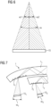
- FIG. 6 The division of the field angle range into two field angle ranges is shown in Figure 6 shown schematically.
- the figure shows a display 15 and the field angle ⁇ under which the display 15 is viewed.
- This field angle is divided into two field angles ⁇ 1 and ⁇ 2, which do not overlap in the present example.
- the partial field angles ⁇ 1 , ⁇ 2 can be selected in such a way that they each represent the largest field angle of a light guide, as shown in Figure 2 To cover the entire field angle range given by the field angle ⁇ , Then two light guides are connected as shown in Figure 2 and which are referred to below as sub-light guides 1 1 , 1 2 of the light guide 1, are arranged one behind the other.
- FIG. 7 shows in a section along a meridian the two sub-light guides 1 1 and 1 2 arranged one behind the other with the coupling structures 3 1 and 3 2 .
- Each of the coupling structures 3 1 , 3 2 is assigned its own display 15 1 , 15 2 , which each show the image area that can be perceived under the corresponding field angle range ⁇ 1, ⁇ 2.
- the field angles ⁇ 1 , ⁇ 2 are selected such that the field angle ranges covered by them can be completely transmitted by the respective light guide 1 1 , 1 2 .
- the partial field angles ⁇ 1 , ⁇ 2 can be, for example, 20°, with the partial field angle ⁇ 1 covering a field angle range from -20° to 0° and the partial field angle ⁇ 2 covering a field angle range from 0° to +20°. Since the sub-light guides 1 1 , 1 2 arranged one behind the other transmit the complete image together, they together form the light guide 1.
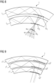
- the coupling out of the light guide 1, which is constructed from sub-light guides 1 1 , 1 2, is in Figure 8 shown schematically.
- Each of the sub-light guides 1 1 , 1 2 has an output coupling structure 13 1 , 13 2 which essentially corresponds to the output coupling structure 13 of Figure 2
- the structures of the base gratings 5, on which the diffraction lens is superimposed are selected so that the light guided through the sub-light guides 1 1 , 1 2 is coupled out at the correct angles.
- the coupling structures 3 1 , 3 2 are adapted accordingly to the base gratings of the coupling-out structures 13 1 , 1 3 2.
- a sufficiently large field of view can be realized.
- diffractive coupling and decoupling structures can be manufactured very flat, and a larger number of sub-light guides can also be arranged one behind the other.
- the light guide with sub-light guides, each of which is designed to transmit a different wavelength range of visible light.
- one sub-light guide with its input coupling structure and its output coupling structure can be designed to transmit red light
- another sub-light guide with its input coupling structure and its output coupling structure can be designed to transmit green light
- a third sub-light guide with its input coupling structure and its output coupling structure can be designed to transmit blue light. In this way, a complete color image can be transmitted by means of three sub-light guides.
- FIG. 9 shows a light guide 1 with three sub-light guides 1 1 , 1 2 , 1 3 and the associated coupling-out structures 13 1 , 13 2 , 13 3.
- Each sub-light guide 1 1 , 1 2 , 1 3 with its associated coupling-in structure (not shown) and its coupling-out structure 13 1 , 13 2 , 13 3 is designed to transmit a color, for example the first sub-light guide 1 1 to transmit red light, the second sub-light guide 1 2 to transmit green light and the third sub-light guide 1 3 to transmit blue light.
- a color image can therefore be transmitted with the three sub-light guides 1 1 , 1 2 , 1 3 .
- each field angle range is to represent a color image
- three substructures 1 1 , 1 2 , 1 3 for red, green and blue light are required for each field angle range defined by a partial field angle ⁇ 1, ⁇ 2.
- there are six sub-light guides in the above example three each for the field angle range defined by the partial field angle ⁇ 1 and three each for the field angle range defined by the partial field angle ⁇ 2.
- the Sub-light guides with diffractive coupling and diffractive coupling can be manufactured quite thin, so that a light guide 1 with six substructures can be manufactured without problems with an acceptable total thickness.
- the in Figure 4 The diffraction lens 11 shown is not color corrected. This is because the angles at which constructive interference occurs depend on the wavelength of the light. The lack of color correction leads to a longitudinal color error and a transverse color error.
- the longitudinal chromatic aberration results from the fact that the angles for the first diffraction maximum differ from one another, so that the lens has different focal lengths for different wavelengths.
- the diffraction lens is designed, for example, so that its focal length for green light corresponds to the radius of curvature of the light guide, the focal length for red light is somewhat smaller and the focal length for blue light is somewhat larger than the radius of curvature of the light guide 1, so that a certain image blurring occurs in the red and blue parts of the image when the green part of the image is sharp.
- the loss of sharpness due to the blurring in the red and blue image components is approximately 0.6 dpt, assuming a radius of curvature of the light guide 1 and a focal length of the diffraction lens 11 of 150 mm each. A loss of sharpness of 0.6 dpt can still be considered acceptable.
- the lateral chromatic aberration is based on the different magnification resulting from the different focal lengths and thus the different image scale of the individual colors in the respective focal plane. While the lateral chromatic aberration does not appear on the optical axis, it increases with distance from the optical axis. If the exit pupil of the diffraction lens is 20 mm behind the coupling structure, lateral chromatic aberrations occur at the edge of an image field of ⁇ 12°, which are on the order of around 10 arc minutes at the edge of the field. Such lateral chromatic aberrations are no longer acceptable and must be corrected.
- One way of correcting the lateral chromatic aberration is to place a correction element in front of the coupling structure 3 of the light guide 1 in an imaging device comprising the light guide 1, which correction element generates a lateral chromatic aberration that is inverse to the lateral chromatic aberration induced by the diffraction lens 11, so that the lateral chromatic aberration of the diffraction lens 11 and the lateral chromatic aberration of the correction element just cancel each other out.
- An example of such a correction element is shown in Figure 10 shown.
- the figure shows a schematic representation of an HMD with an image generator 15 on which an output image is displayed, which is to be converted into a virtual image by an imaging optics.
- this imaging optics comprises a correction element 17 for correcting the lateral chromatic aberration.
- this correction element 17 comprises a classic refractive optical element 19 and a diffractive optical element 21. These two are coordinated with one another in such a way that together they induce a lateral chromatic aberration which compensates for the lateral chromatic aberration of the diffractive lens 11 of the output structure 13.
- the refractive optical element 19 and the diffractive optical element 21 can be shifted relative to one another, which also allows a dynamic lateral chromatic aberration to be compensated.
- a dynamic lateral chromatic aberration is caused by the user's eye movement, which causes lateral chromatic aberrations occurring in the field along edges to change their extent.
- an eye tracker 23 is provided in the present embodiment to determine the direction of view.
- a control unit 25 controls the relative displacement between the refractive optical element 19 and the diffractive element 21 of the correction element 17. If the dynamic lateral chromatic aberration is not to be compensated, it is possible to arrange the refractive optical element 19 and the diffractive optical element 21 fixed relative to one another and to dispense with the eye tracker 23 and the control unit 25.
- the correction element 17 also makes it possible to compensate for the previously mentioned pupil distortion, which occurs due to the guidance of the light rays along the meridians, by suitable design of the refractive optical element 19 and/or the diffractive optical element 21.
- Figure 11 shows an imaging optics for an HMD with a light guide 1 according to the invention and a correction element that only serves to compensate for pupil distortion.
- a parabolic mirror 27 with a radius of curvature of 480 mm is used as the correction element.
- the radius of curvature of the light guide 1 and the focal length of the diffraction lens of the coupling-out structure 13 are again assumed to be 150 mm.
- the starting point of the Figure 10 The beam of rays striking the parabolic mirror 27 from the left is located outside the image at the focal point of the parabolic mirror. Linear astigmatism can also be reduced by creating a quadratic pupil distortion in the longitudinal direction in an analogous manner.
- pupil distortion can also be corrected using other off-axis elements. Correcting pupil distortion also makes longer transmission lengths in the light guide possible.
- the display 15 it is possible to arrange the display 15 closer to the coupling structure if a polarization beam splitter 29 and a delay plate 32 in the form of a ⁇ /4 plate are arranged in front of the coupling structure, as shown in Figure 12
- the coupling with the aid of a polarization beam splitter and a delay plate is shown, for example, in WO 2008/023367 A1 , in particular with reference to Figure 3 , described.
- WO 2008/023367 A1 reference is made to the coupling using a polarization beam splitter and a retardation plate.
- the present invention has been described in detail using exemplary embodiments for explanatory purposes. However, it will be apparent to a person skilled in the art that deviations from the exemplary embodiments can be made within the scope of the invention.
- the number of partial field angles can be greater than two and the number of color channels to be transmitted can be smaller or greater than three.
- a refractive lens such as a Fresnel lens
- the scattering effect can be superimposed on the coupling-in structure instead of being superimposed on the output structure.
- coupling-in and coupling-out structures can be used, for example reflective structures such as partially transparent mirrors instead of diffractive structures, or the diffractive structures described can be replaced by blaze gratings. In the latter case, it is possible to optimize the diffraction structure to a specific diffraction order by selecting the blaze angle appropriately.
- the diffraction lens can also be implemented as a blaze grating. Dichroic partially transparent mirrors can then be used, for example, to couple out a specific wavelength range.
- the coupling-out structures are arranged in the rear surface of the light guide, they can also be arranged in the front surface, so that the light first passes through the rear surface approximately vertically, for example, and only then onto the deflecting/diffractive structure on the front surface. Accordingly, after passing through the light guide, the light can be deflected by a deflecting/diffractive structure on the front surface in the direction of the rear surface, through which it then exits the light guide approximately vertically, for example.
- the invention should therefore not be limited by the described embodiments, but only by the appended claims.
Landscapes
- Physics & Mathematics (AREA)
- General Physics & Mathematics (AREA)
- Optics & Photonics (AREA)
- Optical Couplings Of Light Guides (AREA)
Claims (15)
- Guide de lumière incurvé de manière sphérique (1) destiné à un visiocasque, le guide de lumière (1) étant disposé, en utilisation nominale, devant au moins un œil et possédant, vu de l'œil, une courbure concave avec un certain rayon de courbure, le guide de lumière incurvé de manière sphérique comprenant :- une surface arrière (6) tournée vers l'œil et une surface avant (4) tournée à l'opposé de l'œil,- une structure d'injection (3) destinée à injecter de la lumière dans le guide de lumière (1) de telle sorte que la lumière soit guidée par réflexion sur la surface avant (4) et/ou la surface arrière (6) à travers le guide de lumière (1), et- une structure d'extraction (13) destinée à l'extraction de la lumière guidée à travers le guide de lumière (1),dans lequelle guide de lumière (1) comporte une structure diffusante (11) pour la lumière guidée par le guide de lumière, dont la distance focale est inférieure ou égale en valeur absolue au rayon de courbure du guide de lumière (1), caractérisé en ce quela structure d'injection (3) est conçue de telle sorte qu'elle injecte des rayons lumineux dans le guide de lumière (1) de manière à ce que les rayons lumineux injectés se propagent dans le guide de lumière (1) le long de cercles longitudinaux (7) du guide de lumière (1), etla structure d'extraction (5, 13) se situe plus près que la structure d'injection (3) du grand cercle (9) du guide de lumière (1) qui coupe à angle droit les cercles longitudinaux (7).
- Guide de lumière (1) selon la revendication 1, caractérisé en ce que la structure diffusante (11) est superposée à la structure d'extraction (5, 13) et/ou à la structure d'injection (3).
- Guide de lumière (1) selon la revendication 1 ou la revendication 2, caractérisé en ce que la structure diffusante est une lentille de diffraction (11).
- Guide de lumière (1) selon la revendication 3, caractérisé en ce que la lentille de diffraction (11) comprend des zones qui diffèrent les unes des autres par leur longueur de chemin optique pour la lumière guidée par le guide de lumière (1).
- Guide de lumière (1) selon la revendication 3, caractérisé en ce que la lentille de diffraction (11) comprend des zones transparentes et des zones non transparentes.
- Guide de lumière (1) selon l'une quelconque des revendications 1 à 5, caractérisé en ce que l'effet diffusant de la structure diffusante (11) est centré sur le centre du champ de vision.
- Guide de lumière (1) selon l'une quelconque des revendications 1 à 6, caractérisé en ce que la lumière à injecter dans le guide de lumière (1) possède un spectre angulaire et/ou une plage spectrale et en ce que la structure d'injection (3) ainsi que la structure d'extraction (13) comprennent respectivement plusieurs sous-structures (31, 32, 131, 132, 131, 132, 133) qui injectent dans le guide de lumière (1) ou extraient du guide de lumière (1) différentes parties de la plage spectrale et/ou différentes parties du spectre angulaire.
- Guide de lumière (1) selon la revendication 7, caractérisé en ce qu'il comprend une pluralité de sous-guides de lumière (11, 12, 11, 12, 13) , qui guident respectivement une autre des différentes parties de la plage spectrale et/ou des différentes parties du spectre angulaire de la structure d'injection (3) vers la structure d'extraction (13).
- Guide de lumière (1) selon l'une quelconque des revendications 1 à 8, caractérisé en ce que la structure d'injection (3) est disposée dans le guide de lumière (1) de manière à ce que l'injection puisse être effectuée par l'intermédiaire de la surface arrière (6) du guide de lumière (1).
- Optique d'imagerie comprenant un chemin optique d'imagerie, un guide de lumière (1) et au moins un élément optique de formation d'image, caractérisée en ce qu'elle comprend un guide de lumière (1) selon l'une quelconque des revendications 1 à 9, le guide de lumière (1) étant utilisé en tant que ledit au moins un élément optique de formation d'image.
- Optique d'imagerie selon la revendication 10, caractérisée en ce qu'un élément de correction (17, 27) destiné à corriger préalablement une distorsion pupillaire induite par le guide de lumière est placé en amont de la structure d'injection (3) du guide de lumière (1) sur le chemin optique d'imagerie.
- Optique d'imagerie selon la revendication 10 ou la revendication 11, caractérisée en ce qu'une optique de compensation (27) compensant une erreur chromatique transversale induite par le guide de lumière (1) est placée en amont de la structure d'injection (3) du guide de lumière (1) sur le chemin optique d'imagerie.
- Optique d'imagerie selon l'une quelconque des revendications 10 à 12, caractérisée en ce que l'optique de compensation (27) comprend un élément optique diffractant (21) et un élément optique réfractant (19) qui sont disposés de manière à pouvoir être déplacés l'un par rapport à l'autre perpendiculairement à l'axe optique du chemin optique d'imagerie, et en ce qu'un oculomètre (23) est présent.
- Optique d'imagerie selon l'une quelconque des revendications 10 à 13, caractérisée en ce qu'un diviseur de faisceau à polarisation (29) et une lame à retard (31) sont placés en amont de la structure d'injection (3) du guide de lumière (1) sur le chemin optique d'imagerie.
- Visiocasque comprenant un écran (15) destiné à représenter une image de sortie, et une optique d'imagerie destinée à générer une image virtuelle à partir de l'image de sortie, caractérisé en ce que l'optique d'imagerie est une optique d'imagerie selon l'une quelconque des revendications 10 à 14.
Applications Claiming Priority (2)
| Application Number | Priority Date | Filing Date | Title |
|---|---|---|---|
| DE102017119440.1A DE102017119440A1 (de) | 2017-08-24 | 2017-08-24 | Gekrümmter Lichtleiter, Abbildungsoptik und HMD |
| PCT/EP2018/072757 WO2019038374A1 (fr) | 2017-08-24 | 2018-08-23 | Guide de lumière incurvé, optique d'imagerie et hmd |
Publications (2)
| Publication Number | Publication Date |
|---|---|
| EP3673316A1 EP3673316A1 (fr) | 2020-07-01 |
| EP3673316B1 true EP3673316B1 (fr) | 2024-12-18 |
Family
ID=63452624
Family Applications (1)
| Application Number | Title | Priority Date | Filing Date |
|---|---|---|---|
| EP18762798.9A Active EP3673316B1 (fr) | 2017-08-24 | 2018-08-23 | Guide de lumière incurvé, optique d'imagerie et hmd |
Country Status (5)
| Country | Link |
|---|---|
| US (1) | US11385465B2 (fr) |
| EP (1) | EP3673316B1 (fr) |
| CN (1) | CN111065954B (fr) |
| DE (1) | DE102017119440A1 (fr) |
| WO (1) | WO2019038374A1 (fr) |
Families Citing this family (9)
| Publication number | Priority date | Publication date | Assignee | Title |
|---|---|---|---|---|
| KR102897178B1 (ko) * | 2019-06-23 | 2025-12-05 | 루머스 리미티드 | 포비티드 광학 보정에 의한 디스플레이 |
| JP7417937B2 (ja) * | 2020-03-31 | 2024-01-19 | パナソニックIpマネジメント株式会社 | 表示装置 |
| DE102020205405A1 (de) | 2020-04-29 | 2021-11-04 | Robert Bosch Gesellschaft mit beschränkter Haftung | Lichtleitereinrichtung, Projektionseinrichtung und Verfahren zur Projektion |
| GB2599023B (en) | 2020-09-21 | 2023-02-22 | Trulife Optics Ltd | Cylindrical optical waveguide system |
| US11960088B2 (en) * | 2021-04-28 | 2024-04-16 | Meta Platforms Technologies, Llc | Waveguide configurations in a head-mounted display (HMD) for improved field of view (FOV) |
| US12468178B2 (en) * | 2021-09-29 | 2025-11-11 | Amazon Technologies, Inc. | Ophthalmic lens assembly |
| WO2023086269A2 (fr) * | 2021-11-09 | 2023-05-19 | Google Llc | Guide de lumière transparent mince incurvé doté d'un grand boîtier oculaire |
| DE102023208768A1 (de) * | 2023-09-11 | 2025-03-13 | Robert Bosch Gesellschaft mit beschränkter Haftung | Optikvorrichtung, AR-System und Verfahren zu einer Kompensation einer Verstimmung zwischen einem Combiner und Projektoreinheit des AR-Systems |
| US20250147311A1 (en) * | 2023-11-06 | 2025-05-08 | Google Llc | Lateral color alignment correction for diffractive waveguides |
Family Cites Families (27)
| Publication number | Priority date | Publication date | Assignee | Title |
|---|---|---|---|---|
| US6462882B2 (en) * | 2001-03-01 | 2002-10-08 | Raytheon Company | Light-weight head-mounted display |
| US7119452B2 (en) | 2003-09-03 | 2006-10-10 | General Electric Company | Voltage control for wind generators |
| US7418170B2 (en) | 2004-03-29 | 2008-08-26 | Sony Corporation | Optical device and virtual image display device |
| EP1792225A4 (fr) * | 2004-09-01 | 2010-07-28 | Optical Res Associates | Dispositifs d'affichage tete haute compacts avec element lentille incline/decentre |
| IL177618A (en) * | 2006-08-22 | 2015-02-26 | Lumus Ltd | Optical component in conductive substrate |
| US8139103B2 (en) * | 2006-11-11 | 2012-03-20 | Vuzix Corporation | Traveling lens for video display |
| WO2008129539A2 (fr) * | 2007-04-22 | 2008-10-30 | Lumus Ltd. | Dispositif et système optiques de collimation |
| EP3667399A1 (fr) | 2007-06-04 | 2020-06-17 | Magic Leap, Inc. | Expanseur de faisceau diffractif |
| US8830584B2 (en) | 2007-12-17 | 2014-09-09 | Nokia Corporation | Exit pupil expanders with spherical and aspheric substrates |
| DE102008009095A1 (de) * | 2008-02-14 | 2009-08-20 | Carl Zeiss Ag | Durchsicht-Display-System |
| DE102009010537B4 (de) | 2009-02-25 | 2018-03-01 | Carl Zeiss Smart Optics Gmbh | Strahlvereiniger und Verwendung eines solchen in einer Anzeigevorrichtung |
| EP2246728A1 (fr) | 2009-04-29 | 2010-11-03 | BAE Systems PLC | Affichage monté sur la tête |
| US8842368B2 (en) | 2009-04-29 | 2014-09-23 | Bae Systems Plc | Head mounted display |
| EP2465005A1 (fr) * | 2009-08-14 | 2012-06-20 | Akkolens International B.V. | Optique avec correction variable simultanée d'aberrations |
| US8810913B2 (en) * | 2010-01-25 | 2014-08-19 | Bae Systems Plc | Projection display |
| WO2011110728A1 (fr) | 2010-03-12 | 2011-09-15 | Nokia Corporation | Structures de guidage de lumière |
| DE102011007812B4 (de) | 2011-04-20 | 2018-02-15 | Carl Zeiss Smart Optics Gmbh | Anzeigevorrichtung |
| DE102011055777B4 (de) * | 2011-11-28 | 2015-02-26 | Carl Zeiss Ag | Optisches Gerät, optisches Element und Verfahren zu seiner Herstellung |
| DE102012213685B4 (de) * | 2012-08-02 | 2020-12-24 | tooz technologies GmbH | Anzeigevorrichtung |
| DE102013223963B4 (de) | 2013-11-22 | 2015-07-02 | Carl Zeiss Ag | Abbildungsoptik sowie Anzeigevorrichtung mit einer solchen Abbildungsoptik |
| DE102013223964B3 (de) | 2013-11-22 | 2015-05-13 | Carl Zeiss Ag | Abbildungsoptik sowie Anzeigevorrichtung mit einer solchen Abbildungsoptik |
| WO2016063418A1 (fr) * | 2014-10-24 | 2016-04-28 | オリンパス株式会社 | Système optique excentrique, et dispositif de projection d'image utilisant le système optique excentrique |
| US20160341975A1 (en) | 2015-05-21 | 2016-11-24 | Jahwa Electronics Co., Ltd. | Camera lens module |
| DE102015116297A1 (de) * | 2015-09-25 | 2017-03-30 | Carl Zeiss Smart Optics Gmbh | Abbildungsoptik sowie Anzeigevorrichtung mit einer solchen Abbildungsoptik |
| DE102015122055B4 (de) | 2015-12-17 | 2018-08-30 | Carl Zeiss Ag | Optisches System sowie Verfahren zum Übertragen eines Quellbildes |
| US9897811B2 (en) * | 2016-04-07 | 2018-02-20 | Google Llc | Curved eyepiece with color correction for head wearable display |
| US10353202B2 (en) * | 2016-06-09 | 2019-07-16 | Microsoft Technology Licensing, Llc | Wrapped waveguide with large field of view |
-
2017
- 2017-08-24 DE DE102017119440.1A patent/DE102017119440A1/de active Pending
-
2018
- 2018-08-23 EP EP18762798.9A patent/EP3673316B1/fr active Active
- 2018-08-23 US US16/641,250 patent/US11385465B2/en active Active
- 2018-08-23 WO PCT/EP2018/072757 patent/WO2019038374A1/fr not_active Ceased
- 2018-08-23 CN CN201880054971.0A patent/CN111065954B/zh active Active
Also Published As
| Publication number | Publication date |
|---|---|
| US11385465B2 (en) | 2022-07-12 |
| EP3673316A1 (fr) | 2020-07-01 |
| CN111065954B (zh) | 2025-02-07 |
| WO2019038374A1 (fr) | 2019-02-28 |
| DE102017119440A1 (de) | 2019-02-28 |
| CN111065954A (zh) | 2020-04-24 |
| US20200225475A1 (en) | 2020-07-16 |
Similar Documents
| Publication | Publication Date | Title |
|---|---|---|
| EP3673316B1 (fr) | Guide de lumière incurvé, optique d'imagerie et hmd | |
| DE102013219625B3 (de) | Brillenglas für eine auf den Kopf eines Benutzers aufsetzbare und ein Bild erzeugende Anzeigevorrichtung sowie Anzeigevorrichtung mit einem solchen Brillenglas | |
| EP3391122B1 (fr) | Système optique ainsi que procédé pour le transfert d'une image source | |
| DE3878479T2 (de) | Binokulare, auf einem helm montierbare weitwinkelanzeige. | |
| DE69411711T2 (de) | Auf dem kopf getragenes anzeigesystem mit diffraktiven optischen elementen | |
| EP3710878B1 (fr) | Guide de lumière pour hmd, hmd et procédé de transfert d'une image dans un hmd | |
| DE102012213685B4 (de) | Anzeigevorrichtung | |
| DE69430983T2 (de) | Vorrichtung zum Anzeigen von Bildern | |
| EP3555688B1 (fr) | Lunettes intelligentes, verre de lunettes pour des lunettes intelligentes et procédé permettant de générer une image sur la rétine | |
| DE102013219623B4 (de) | Brillenglas für eine auf den Kopf eines Benutzers aufsetzbare und ein Bild erzeugende Anzeigevorrichtung sowie Anzeigevorrichtung mit einem solchen Brillenglas | |
| DE102013219626A1 (de) | Brillenglas für eine auf den Kopf eines Benutzers aufsetzbare und ein Bild erzeugende Anzeigevorrichtung und Anzeigevorrichtung mit einem solchen Brillenglas | |
| DE2843661B2 (de) | Sichtgerät mit einer am Kopf des Beobachters befestigbaren Sichtplatte | |
| DE102015221774B4 (de) | Optisches System und Verfahren zur Erzeugung eines zwei- oder dreidimensionalen Bildes | |
| DE102014118490B4 (de) | Anzeigevorrichtungen | |
| EP3210068B1 (fr) | Optique de visualisation et lunettes intelligentes | |
| DE102017211932A1 (de) | Projektionsvorrichtung für eine Datenbrille, Datenbrille sowie Verfahren zum Betreiben einer Projektionsvorrichtung | |
| DE102016217347A1 (de) | Sehhilfe mit einer Datenbrille und einer Haftschale | |
| DE69804625T2 (de) | Mit einem asphärischen spiegel ausgerüstete optische vorrichtung für helmvisier | |
| DE102020205910A1 (de) | Datenbrille zur virtuellen Netzhautanzeige und Verfahren zum Betreiben derselben | |
| WO2024133304A1 (fr) | Dispositif de génération et d'affichage d'une image dans un champ d'observation en utilisant un multiplicateur de pupille | |
| DE102021129587B3 (de) | Kopftragbare Anzeigevorrichtung | |
| DE102007036974A1 (de) | HMD-Vorrichtung | |
| DE102024114655A1 (de) | Brillenglas für eine auf den Kopf eines Benutzers aufsetzbare und ein Bild erzeugende Anzeigevorrichtung sowie Anzeigevorrichtung mit einem solchen Brillenglas | |
| DE102022105093A1 (de) | Visorsystem mit kompakter Spiegeloptik | |
| EP4689770A1 (fr) | Dispositif d'affichage |
Legal Events
| Date | Code | Title | Description |
|---|---|---|---|
| STAA | Information on the status of an ep patent application or granted ep patent |
Free format text: STATUS: UNKNOWN |
|
| STAA | Information on the status of an ep patent application or granted ep patent |
Free format text: STATUS: THE INTERNATIONAL PUBLICATION HAS BEEN MADE |
|
| PUAI | Public reference made under article 153(3) epc to a published international application that has entered the european phase |
Free format text: ORIGINAL CODE: 0009012 |
|
| STAA | Information on the status of an ep patent application or granted ep patent |
Free format text: STATUS: REQUEST FOR EXAMINATION WAS MADE |
|
| 17P | Request for examination filed |
Effective date: 20200313 |
|
| AK | Designated contracting states |
Kind code of ref document: A1 Designated state(s): AL AT BE BG CH CY CZ DE DK EE ES FI FR GB GR HR HU IE IS IT LI LT LU LV MC MK MT NL NO PL PT RO RS SE SI SK SM TR |
|
| AX | Request for extension of the european patent |
Extension state: BA ME |
|
| DAV | Request for validation of the european patent (deleted) | ||
| DAX | Request for extension of the european patent (deleted) | ||
| STAA | Information on the status of an ep patent application or granted ep patent |
Free format text: STATUS: EXAMINATION IS IN PROGRESS |
|
| 17Q | First examination report despatched |
Effective date: 20220819 |
|
| GRAP | Despatch of communication of intention to grant a patent |
Free format text: ORIGINAL CODE: EPIDOSNIGR1 |
|
| STAA | Information on the status of an ep patent application or granted ep patent |
Free format text: STATUS: GRANT OF PATENT IS INTENDED |
|
| INTG | Intention to grant announced |
Effective date: 20240712 |
|
| GRAS | Grant fee paid |
Free format text: ORIGINAL CODE: EPIDOSNIGR3 |
|
| GRAA | (expected) grant |
Free format text: ORIGINAL CODE: 0009210 |
|
| STAA | Information on the status of an ep patent application or granted ep patent |
Free format text: STATUS: THE PATENT HAS BEEN GRANTED |
|
| AK | Designated contracting states |
Kind code of ref document: B1 Designated state(s): AL AT BE BG CH CY CZ DE DK EE ES FI FR GB GR HR HU IE IS IT LI LT LU LV MC MK MT NL NO PL PT RO RS SE SI SK SM TR |
|
| REG | Reference to a national code |
Ref country code: GB Ref legal event code: FG4D Free format text: NOT ENGLISH |
|
| REG | Reference to a national code |
Ref country code: CH Ref legal event code: EP |
|
| REG | Reference to a national code |
Ref country code: DE Ref legal event code: R096 Ref document number: 502018015429 Country of ref document: DE |
|
| REG | Reference to a national code |
Ref country code: IE Ref legal event code: FG4D Free format text: LANGUAGE OF EP DOCUMENT: GERMAN |
|
| REG | Reference to a national code |
Ref country code: LT Ref legal event code: MG9D |
|
| PG25 | Lapsed in a contracting state [announced via postgrant information from national office to epo] |
Ref country code: HR Free format text: LAPSE BECAUSE OF FAILURE TO SUBMIT A TRANSLATION OF THE DESCRIPTION OR TO PAY THE FEE WITHIN THE PRESCRIBED TIME-LIMIT Effective date: 20241218 |
|
| PG25 | Lapsed in a contracting state [announced via postgrant information from national office to epo] |
Ref country code: FI Free format text: LAPSE BECAUSE OF FAILURE TO SUBMIT A TRANSLATION OF THE DESCRIPTION OR TO PAY THE FEE WITHIN THE PRESCRIBED TIME-LIMIT Effective date: 20241218 |
|
| PG25 | Lapsed in a contracting state [announced via postgrant information from national office to epo] |
Ref country code: BG Free format text: LAPSE BECAUSE OF FAILURE TO SUBMIT A TRANSLATION OF THE DESCRIPTION OR TO PAY THE FEE WITHIN THE PRESCRIBED TIME-LIMIT Effective date: 20241218 |
|
| PG25 | Lapsed in a contracting state [announced via postgrant information from national office to epo] |
Ref country code: NO Free format text: LAPSE BECAUSE OF FAILURE TO SUBMIT A TRANSLATION OF THE DESCRIPTION OR TO PAY THE FEE WITHIN THE PRESCRIBED TIME-LIMIT Effective date: 20250318 |
|
| REG | Reference to a national code |
Ref country code: NL Ref legal event code: MP Effective date: 20241218 |
|
| PG25 | Lapsed in a contracting state [announced via postgrant information from national office to epo] |
Ref country code: GR Free format text: LAPSE BECAUSE OF FAILURE TO SUBMIT A TRANSLATION OF THE DESCRIPTION OR TO PAY THE FEE WITHIN THE PRESCRIBED TIME-LIMIT Effective date: 20250319 Ref country code: LV Free format text: LAPSE BECAUSE OF FAILURE TO SUBMIT A TRANSLATION OF THE DESCRIPTION OR TO PAY THE FEE WITHIN THE PRESCRIBED TIME-LIMIT Effective date: 20241218 |
|
| PG25 | Lapsed in a contracting state [announced via postgrant information from national office to epo] |
Ref country code: RS Free format text: LAPSE BECAUSE OF FAILURE TO SUBMIT A TRANSLATION OF THE DESCRIPTION OR TO PAY THE FEE WITHIN THE PRESCRIBED TIME-LIMIT Effective date: 20250318 |
|
| PG25 | Lapsed in a contracting state [announced via postgrant information from national office to epo] |
Ref country code: NL Free format text: LAPSE BECAUSE OF FAILURE TO SUBMIT A TRANSLATION OF THE DESCRIPTION OR TO PAY THE FEE WITHIN THE PRESCRIBED TIME-LIMIT Effective date: 20241218 |
|
| PG25 | Lapsed in a contracting state [announced via postgrant information from national office to epo] |
Ref country code: SM Free format text: LAPSE BECAUSE OF FAILURE TO SUBMIT A TRANSLATION OF THE DESCRIPTION OR TO PAY THE FEE WITHIN THE PRESCRIBED TIME-LIMIT Effective date: 20241218 |
|
| PG25 | Lapsed in a contracting state [announced via postgrant information from national office to epo] |
Ref country code: PL Free format text: LAPSE BECAUSE OF FAILURE TO SUBMIT A TRANSLATION OF THE DESCRIPTION OR TO PAY THE FEE WITHIN THE PRESCRIBED TIME-LIMIT Effective date: 20241218 |
|
| PG25 | Lapsed in a contracting state [announced via postgrant information from national office to epo] |
Ref country code: ES Free format text: LAPSE BECAUSE OF FAILURE TO SUBMIT A TRANSLATION OF THE DESCRIPTION OR TO PAY THE FEE WITHIN THE PRESCRIBED TIME-LIMIT Effective date: 20241218 |
|
| PG25 | Lapsed in a contracting state [announced via postgrant information from national office to epo] |
Ref country code: IS Free format text: LAPSE BECAUSE OF FAILURE TO SUBMIT A TRANSLATION OF THE DESCRIPTION OR TO PAY THE FEE WITHIN THE PRESCRIBED TIME-LIMIT Effective date: 20250418 |
|
| PG25 | Lapsed in a contracting state [announced via postgrant information from national office to epo] |
Ref country code: PT Free format text: LAPSE BECAUSE OF FAILURE TO SUBMIT A TRANSLATION OF THE DESCRIPTION OR TO PAY THE FEE WITHIN THE PRESCRIBED TIME-LIMIT Effective date: 20250421 |
|
| PG25 | Lapsed in a contracting state [announced via postgrant information from national office to epo] |
Ref country code: EE Free format text: LAPSE BECAUSE OF FAILURE TO SUBMIT A TRANSLATION OF THE DESCRIPTION OR TO PAY THE FEE WITHIN THE PRESCRIBED TIME-LIMIT Effective date: 20241218 |
|
| PG25 | Lapsed in a contracting state [announced via postgrant information from national office to epo] |
Ref country code: RO Free format text: LAPSE BECAUSE OF FAILURE TO SUBMIT A TRANSLATION OF THE DESCRIPTION OR TO PAY THE FEE WITHIN THE PRESCRIBED TIME-LIMIT Effective date: 20241218 |
|
| PG25 | Lapsed in a contracting state [announced via postgrant information from national office to epo] |
Ref country code: SK Free format text: LAPSE BECAUSE OF FAILURE TO SUBMIT A TRANSLATION OF THE DESCRIPTION OR TO PAY THE FEE WITHIN THE PRESCRIBED TIME-LIMIT Effective date: 20241218 |
|
| PG25 | Lapsed in a contracting state [announced via postgrant information from national office to epo] |
Ref country code: CZ Free format text: LAPSE BECAUSE OF FAILURE TO SUBMIT A TRANSLATION OF THE DESCRIPTION OR TO PAY THE FEE WITHIN THE PRESCRIBED TIME-LIMIT Effective date: 20241218 |
|
| PG25 | Lapsed in a contracting state [announced via postgrant information from national office to epo] |
Ref country code: IT Free format text: LAPSE BECAUSE OF FAILURE TO SUBMIT A TRANSLATION OF THE DESCRIPTION OR TO PAY THE FEE WITHIN THE PRESCRIBED TIME-LIMIT Effective date: 20241218 |
|
| PG25 | Lapsed in a contracting state [announced via postgrant information from national office to epo] |
Ref country code: SE Free format text: LAPSE BECAUSE OF FAILURE TO SUBMIT A TRANSLATION OF THE DESCRIPTION OR TO PAY THE FEE WITHIN THE PRESCRIBED TIME-LIMIT Effective date: 20241218 |
|
| REG | Reference to a national code |
Ref country code: DE Ref legal event code: R097 Ref document number: 502018015429 Country of ref document: DE |
|
| PG25 | Lapsed in a contracting state [announced via postgrant information from national office to epo] |
Ref country code: DK Free format text: LAPSE BECAUSE OF FAILURE TO SUBMIT A TRANSLATION OF THE DESCRIPTION OR TO PAY THE FEE WITHIN THE PRESCRIBED TIME-LIMIT Effective date: 20241218 |
|
| PGFP | Annual fee paid to national office [announced via postgrant information from national office to epo] |
Ref country code: DE Payment date: 20250820 Year of fee payment: 8 |
|
| PGFP | Annual fee paid to national office [announced via postgrant information from national office to epo] |
Ref country code: GB Payment date: 20250820 Year of fee payment: 8 |
|
| PGFP | Annual fee paid to national office [announced via postgrant information from national office to epo] |
Ref country code: FR Payment date: 20250828 Year of fee payment: 8 |
|
| PLBE | No opposition filed within time limit |
Free format text: ORIGINAL CODE: 0009261 |
|
| STAA | Information on the status of an ep patent application or granted ep patent |
Free format text: STATUS: NO OPPOSITION FILED WITHIN TIME LIMIT |
|
| REG | Reference to a national code |
Ref country code: CH Ref legal event code: L10 Free format text: ST27 STATUS EVENT CODE: U-0-0-L10-L00 (AS PROVIDED BY THE NATIONAL OFFICE) Effective date: 20251029 |
|
| 26N | No opposition filed |
Effective date: 20250919 |
|
| REG | Reference to a national code |
Ref country code: CH Ref legal event code: H13 Free format text: ST27 STATUS EVENT CODE: U-0-0-H10-H13 (AS PROVIDED BY THE NATIONAL OFFICE) Effective date: 20260324 |
|
| PG25 | Lapsed in a contracting state [announced via postgrant information from national office to epo] |
Ref country code: MC Free format text: LAPSE BECAUSE OF FAILURE TO SUBMIT A TRANSLATION OF THE DESCRIPTION OR TO PAY THE FEE WITHIN THE PRESCRIBED TIME-LIMIT Effective date: 20241218 |
|
| PG25 | Lapsed in a contracting state [announced via postgrant information from national office to epo] |
Ref country code: LU Free format text: LAPSE BECAUSE OF NON-PAYMENT OF DUE FEES Effective date: 20250823 |
|
| PG25 | Lapsed in a contracting state [announced via postgrant information from national office to epo] |
Ref country code: CH Free format text: LAPSE BECAUSE OF NON-PAYMENT OF DUE FEES Effective date: 20250831 |