EP3673327B1 - Polarisationsunabhängige abstimmbare linse und verfahren zu ihrer herstellung - Google Patents
Polarisationsunabhängige abstimmbare linse und verfahren zu ihrer herstellung Download PDFInfo
- Publication number
- EP3673327B1 EP3673327B1 EP18755850.7A EP18755850A EP3673327B1 EP 3673327 B1 EP3673327 B1 EP 3673327B1 EP 18755850 A EP18755850 A EP 18755850A EP 3673327 B1 EP3673327 B1 EP 3673327B1
- Authority
- EP
- European Patent Office
- Prior art keywords
- alignment
- pretilt
- angle
- molecules
- layer
- Prior art date
- Legal status (The legal status is an assumption and is not a legal conclusion. Google has not performed a legal analysis and makes no representation as to the accuracy of the status listed.)
- Active
Links
Images




Classifications
-
- G—PHYSICS
- G02—OPTICS
- G02F—OPTICAL DEVICES OR ARRANGEMENTS FOR THE CONTROL OF LIGHT BY MODIFICATION OF THE OPTICAL PROPERTIES OF THE MEDIA OF THE ELEMENTS INVOLVED THEREIN; NON-LINEAR OPTICS; FREQUENCY-CHANGING OF LIGHT; OPTICAL LOGIC ELEMENTS; OPTICAL ANALOGUE/DIGITAL CONVERTERS
- G02F1/00—Devices or arrangements for the control of the intensity, colour, phase, polarisation or direction of light arriving from an independent light source, e.g. switching, gating or modulating; Non-linear optics
- G02F1/01—Devices or arrangements for the control of the intensity, colour, phase, polarisation or direction of light arriving from an independent light source, e.g. switching, gating or modulating; Non-linear optics for the control of the intensity, phase, polarisation or colour
- G02F1/13—Devices or arrangements for the control of the intensity, colour, phase, polarisation or direction of light arriving from an independent light source, e.g. switching, gating or modulating; Non-linear optics for the control of the intensity, phase, polarisation or colour based on liquid crystals, e.g. single liquid crystal display cells
- G02F1/133—Constructional arrangements; Operation of liquid crystal cells; Circuit arrangements
- G02F1/1333—Constructional arrangements; Manufacturing methods
- G02F1/1335—Structural association of cells with optical devices, e.g. polarisers or reflectors
- G02F1/133526—Lenses, e.g. microlenses or Fresnel lenses
-
- G—PHYSICS
- G02—OPTICS
- G02F—OPTICAL DEVICES OR ARRANGEMENTS FOR THE CONTROL OF LIGHT BY MODIFICATION OF THE OPTICAL PROPERTIES OF THE MEDIA OF THE ELEMENTS INVOLVED THEREIN; NON-LINEAR OPTICS; FREQUENCY-CHANGING OF LIGHT; OPTICAL LOGIC ELEMENTS; OPTICAL ANALOGUE/DIGITAL CONVERTERS
- G02F1/00—Devices or arrangements for the control of the intensity, colour, phase, polarisation or direction of light arriving from an independent light source, e.g. switching, gating or modulating; Non-linear optics
- G02F1/01—Devices or arrangements for the control of the intensity, colour, phase, polarisation or direction of light arriving from an independent light source, e.g. switching, gating or modulating; Non-linear optics for the control of the intensity, phase, polarisation or colour
- G02F1/13—Devices or arrangements for the control of the intensity, colour, phase, polarisation or direction of light arriving from an independent light source, e.g. switching, gating or modulating; Non-linear optics for the control of the intensity, phase, polarisation or colour based on liquid crystals, e.g. single liquid crystal display cells
- G02F1/133—Constructional arrangements; Operation of liquid crystal cells; Circuit arrangements
- G02F1/1333—Constructional arrangements; Manufacturing methods
- G02F1/133371—Cells with varying thickness of the liquid crystal layer
-
- G—PHYSICS
- G02—OPTICS
- G02C—SPECTACLES; SUNGLASSES OR GOGGLES INSOFAR AS THEY HAVE THE SAME FEATURES AS SPECTACLES; CONTACT LENSES
- G02C7/00—Optical parts
- G02C7/02—Lenses; Lens systems ; Methods of designing lenses
- G02C7/08—Auxiliary lenses; Arrangements for varying focal length
- G02C7/081—Ophthalmic lenses with variable focal length
- G02C7/083—Electrooptic lenses
-
- G—PHYSICS
- G02—OPTICS
- G02F—OPTICAL DEVICES OR ARRANGEMENTS FOR THE CONTROL OF LIGHT BY MODIFICATION OF THE OPTICAL PROPERTIES OF THE MEDIA OF THE ELEMENTS INVOLVED THEREIN; NON-LINEAR OPTICS; FREQUENCY-CHANGING OF LIGHT; OPTICAL LOGIC ELEMENTS; OPTICAL ANALOGUE/DIGITAL CONVERTERS
- G02F1/00—Devices or arrangements for the control of the intensity, colour, phase, polarisation or direction of light arriving from an independent light source, e.g. switching, gating or modulating; Non-linear optics
- G02F1/01—Devices or arrangements for the control of the intensity, colour, phase, polarisation or direction of light arriving from an independent light source, e.g. switching, gating or modulating; Non-linear optics for the control of the intensity, phase, polarisation or colour
- G02F1/13—Devices or arrangements for the control of the intensity, colour, phase, polarisation or direction of light arriving from an independent light source, e.g. switching, gating or modulating; Non-linear optics for the control of the intensity, phase, polarisation or colour based on liquid crystals, e.g. single liquid crystal display cells
- G02F1/133—Constructional arrangements; Operation of liquid crystal cells; Circuit arrangements
- G02F1/1333—Constructional arrangements; Manufacturing methods
- G02F1/1337—Surface-induced orientation of the liquid crystal molecules, e.g. by alignment layers
-
- G—PHYSICS
- G02—OPTICS
- G02F—OPTICAL DEVICES OR ARRANGEMENTS FOR THE CONTROL OF LIGHT BY MODIFICATION OF THE OPTICAL PROPERTIES OF THE MEDIA OF THE ELEMENTS INVOLVED THEREIN; NON-LINEAR OPTICS; FREQUENCY-CHANGING OF LIGHT; OPTICAL LOGIC ELEMENTS; OPTICAL ANALOGUE/DIGITAL CONVERTERS
- G02F1/00—Devices or arrangements for the control of the intensity, colour, phase, polarisation or direction of light arriving from an independent light source, e.g. switching, gating or modulating; Non-linear optics
- G02F1/29—Devices or arrangements for the control of the intensity, colour, phase, polarisation or direction of light arriving from an independent light source, e.g. switching, gating or modulating; Non-linear optics for the control of the position or the direction of light beams, i.e. deflection
-
- G—PHYSICS
- G02—OPTICS
- G02B—OPTICAL ELEMENTS, SYSTEMS OR APPARATUS
- G02B3/00—Simple or compound lenses
- G02B3/02—Simple or compound lenses with non-spherical faces
- G02B3/08—Simple or compound lenses with non-spherical faces with discontinuous faces, e.g. Fresnel lens
-
- G—PHYSICS
- G02—OPTICS
- G02C—SPECTACLES; SUNGLASSES OR GOGGLES INSOFAR AS THEY HAVE THE SAME FEATURES AS SPECTACLES; CONTACT LENSES
- G02C2202/00—Generic optical aspects applicable to one or more of the subgroups of G02C7/00
- G02C2202/20—Diffractive and Fresnel lenses or lens portions
-
- G—PHYSICS
- G02—OPTICS
- G02F—OPTICAL DEVICES OR ARRANGEMENTS FOR THE CONTROL OF LIGHT BY MODIFICATION OF THE OPTICAL PROPERTIES OF THE MEDIA OF THE ELEMENTS INVOLVED THEREIN; NON-LINEAR OPTICS; FREQUENCY-CHANGING OF LIGHT; OPTICAL LOGIC ELEMENTS; OPTICAL ANALOGUE/DIGITAL CONVERTERS
- G02F1/00—Devices or arrangements for the control of the intensity, colour, phase, polarisation or direction of light arriving from an independent light source, e.g. switching, gating or modulating; Non-linear optics
- G02F1/01—Devices or arrangements for the control of the intensity, colour, phase, polarisation or direction of light arriving from an independent light source, e.g. switching, gating or modulating; Non-linear optics for the control of the intensity, phase, polarisation or colour
- G02F1/13—Devices or arrangements for the control of the intensity, colour, phase, polarisation or direction of light arriving from an independent light source, e.g. switching, gating or modulating; Non-linear optics for the control of the intensity, phase, polarisation or colour based on liquid crystals, e.g. single liquid crystal display cells
- G02F1/133—Constructional arrangements; Operation of liquid crystal cells; Circuit arrangements
- G02F1/1333—Constructional arrangements; Manufacturing methods
- G02F1/133377—Cells with plural compartments or having plurality of liquid crystal microcells partitioned by walls, e.g. one microcell per pixel
-
- G—PHYSICS
- G02—OPTICS
- G02F—OPTICAL DEVICES OR ARRANGEMENTS FOR THE CONTROL OF LIGHT BY MODIFICATION OF THE OPTICAL PROPERTIES OF THE MEDIA OF THE ELEMENTS INVOLVED THEREIN; NON-LINEAR OPTICS; FREQUENCY-CHANGING OF LIGHT; OPTICAL LOGIC ELEMENTS; OPTICAL ANALOGUE/DIGITAL CONVERTERS
- G02F1/00—Devices or arrangements for the control of the intensity, colour, phase, polarisation or direction of light arriving from an independent light source, e.g. switching, gating or modulating; Non-linear optics
- G02F1/01—Devices or arrangements for the control of the intensity, colour, phase, polarisation or direction of light arriving from an independent light source, e.g. switching, gating or modulating; Non-linear optics for the control of the intensity, phase, polarisation or colour
- G02F1/13—Devices or arrangements for the control of the intensity, colour, phase, polarisation or direction of light arriving from an independent light source, e.g. switching, gating or modulating; Non-linear optics for the control of the intensity, phase, polarisation or colour based on liquid crystals, e.g. single liquid crystal display cells
- G02F1/133—Constructional arrangements; Operation of liquid crystal cells; Circuit arrangements
- G02F1/1333—Constructional arrangements; Manufacturing methods
- G02F1/1337—Surface-induced orientation of the liquid crystal molecules, e.g. by alignment layers
- G02F1/133742—Surface-induced orientation of the liquid crystal molecules, e.g. by alignment layers for homeotropic alignment
-
- G—PHYSICS
- G02—OPTICS
- G02F—OPTICAL DEVICES OR ARRANGEMENTS FOR THE CONTROL OF LIGHT BY MODIFICATION OF THE OPTICAL PROPERTIES OF THE MEDIA OF THE ELEMENTS INVOLVED THEREIN; NON-LINEAR OPTICS; FREQUENCY-CHANGING OF LIGHT; OPTICAL LOGIC ELEMENTS; OPTICAL ANALOGUE/DIGITAL CONVERTERS
- G02F1/00—Devices or arrangements for the control of the intensity, colour, phase, polarisation or direction of light arriving from an independent light source, e.g. switching, gating or modulating; Non-linear optics
- G02F1/01—Devices or arrangements for the control of the intensity, colour, phase, polarisation or direction of light arriving from an independent light source, e.g. switching, gating or modulating; Non-linear optics for the control of the intensity, phase, polarisation or colour
- G02F1/13—Devices or arrangements for the control of the intensity, colour, phase, polarisation or direction of light arriving from an independent light source, e.g. switching, gating or modulating; Non-linear optics for the control of the intensity, phase, polarisation or colour based on liquid crystals, e.g. single liquid crystal display cells
- G02F1/133—Constructional arrangements; Operation of liquid crystal cells; Circuit arrangements
- G02F1/1333—Constructional arrangements; Manufacturing methods
- G02F1/1337—Surface-induced orientation of the liquid crystal molecules, e.g. by alignment layers
- G02F1/133746—Surface-induced orientation of the liquid crystal molecules, e.g. by alignment layers for high pretilt angles, i.e. higher than 15 degrees
-
- G—PHYSICS
- G02—OPTICS
- G02F—OPTICAL DEVICES OR ARRANGEMENTS FOR THE CONTROL OF LIGHT BY MODIFICATION OF THE OPTICAL PROPERTIES OF THE MEDIA OF THE ELEMENTS INVOLVED THEREIN; NON-LINEAR OPTICS; FREQUENCY-CHANGING OF LIGHT; OPTICAL LOGIC ELEMENTS; OPTICAL ANALOGUE/DIGITAL CONVERTERS
- G02F1/00—Devices or arrangements for the control of the intensity, colour, phase, polarisation or direction of light arriving from an independent light source, e.g. switching, gating or modulating; Non-linear optics
- G02F1/01—Devices or arrangements for the control of the intensity, colour, phase, polarisation or direction of light arriving from an independent light source, e.g. switching, gating or modulating; Non-linear optics for the control of the intensity, phase, polarisation or colour
- G02F1/13—Devices or arrangements for the control of the intensity, colour, phase, polarisation or direction of light arriving from an independent light source, e.g. switching, gating or modulating; Non-linear optics for the control of the intensity, phase, polarisation or colour based on liquid crystals, e.g. single liquid crystal display cells
- G02F1/133—Constructional arrangements; Operation of liquid crystal cells; Circuit arrangements
- G02F1/1333—Constructional arrangements; Manufacturing methods
- G02F1/1337—Surface-induced orientation of the liquid crystal molecules, e.g. by alignment layers
- G02F1/133753—Surface-induced orientation of the liquid crystal molecules, e.g. by alignment layers with different alignment orientations or pretilt angles on a same surface, e.g. for grey scale or improved viewing angle
-
- G—PHYSICS
- G02—OPTICS
- G02F—OPTICAL DEVICES OR ARRANGEMENTS FOR THE CONTROL OF LIGHT BY MODIFICATION OF THE OPTICAL PROPERTIES OF THE MEDIA OF THE ELEMENTS INVOLVED THEREIN; NON-LINEAR OPTICS; FREQUENCY-CHANGING OF LIGHT; OPTICAL LOGIC ELEMENTS; OPTICAL ANALOGUE/DIGITAL CONVERTERS
- G02F1/00—Devices or arrangements for the control of the intensity, colour, phase, polarisation or direction of light arriving from an independent light source, e.g. switching, gating or modulating; Non-linear optics
- G02F1/01—Devices or arrangements for the control of the intensity, colour, phase, polarisation or direction of light arriving from an independent light source, e.g. switching, gating or modulating; Non-linear optics for the control of the intensity, phase, polarisation or colour
- G02F1/13—Devices or arrangements for the control of the intensity, colour, phase, polarisation or direction of light arriving from an independent light source, e.g. switching, gating or modulating; Non-linear optics for the control of the intensity, phase, polarisation or colour based on liquid crystals, e.g. single liquid crystal display cells
- G02F1/133—Constructional arrangements; Operation of liquid crystal cells; Circuit arrangements
- G02F1/1333—Constructional arrangements; Manufacturing methods
- G02F1/1337—Surface-induced orientation of the liquid crystal molecules, e.g. by alignment layers
- G02F1/133753—Surface-induced orientation of the liquid crystal molecules, e.g. by alignment layers with different alignment orientations or pretilt angles on a same surface, e.g. for grey scale or improved viewing angle
- G02F1/133757—Surface-induced orientation of the liquid crystal molecules, e.g. by alignment layers with different alignment orientations or pretilt angles on a same surface, e.g. for grey scale or improved viewing angle with different alignment orientations
-
- G—PHYSICS
- G02—OPTICS
- G02F—OPTICAL DEVICES OR ARRANGEMENTS FOR THE CONTROL OF LIGHT BY MODIFICATION OF THE OPTICAL PROPERTIES OF THE MEDIA OF THE ELEMENTS INVOLVED THEREIN; NON-LINEAR OPTICS; FREQUENCY-CHANGING OF LIGHT; OPTICAL LOGIC ELEMENTS; OPTICAL ANALOGUE/DIGITAL CONVERTERS
- G02F1/00—Devices or arrangements for the control of the intensity, colour, phase, polarisation or direction of light arriving from an independent light source, e.g. switching, gating or modulating; Non-linear optics
- G02F1/01—Devices or arrangements for the control of the intensity, colour, phase, polarisation or direction of light arriving from an independent light source, e.g. switching, gating or modulating; Non-linear optics for the control of the intensity, phase, polarisation or colour
- G02F1/13—Devices or arrangements for the control of the intensity, colour, phase, polarisation or direction of light arriving from an independent light source, e.g. switching, gating or modulating; Non-linear optics for the control of the intensity, phase, polarisation or colour based on liquid crystals, e.g. single liquid crystal display cells
- G02F1/133—Constructional arrangements; Operation of liquid crystal cells; Circuit arrangements
- G02F1/1333—Constructional arrangements; Manufacturing methods
- G02F1/1337—Surface-induced orientation of the liquid crystal molecules, e.g. by alignment layers
- G02F1/133753—Surface-induced orientation of the liquid crystal molecules, e.g. by alignment layers with different alignment orientations or pretilt angles on a same surface, e.g. for grey scale or improved viewing angle
- G02F1/133761—Surface-induced orientation of the liquid crystal molecules, e.g. by alignment layers with different alignment orientations or pretilt angles on a same surface, e.g. for grey scale or improved viewing angle with different pretilt angles
-
- G—PHYSICS
- G02—OPTICS
- G02F—OPTICAL DEVICES OR ARRANGEMENTS FOR THE CONTROL OF LIGHT BY MODIFICATION OF THE OPTICAL PROPERTIES OF THE MEDIA OF THE ELEMENTS INVOLVED THEREIN; NON-LINEAR OPTICS; FREQUENCY-CHANGING OF LIGHT; OPTICAL LOGIC ELEMENTS; OPTICAL ANALOGUE/DIGITAL CONVERTERS
- G02F1/00—Devices or arrangements for the control of the intensity, colour, phase, polarisation or direction of light arriving from an independent light source, e.g. switching, gating or modulating; Non-linear optics
- G02F1/01—Devices or arrangements for the control of the intensity, colour, phase, polarisation or direction of light arriving from an independent light source, e.g. switching, gating or modulating; Non-linear optics for the control of the intensity, phase, polarisation or colour
- G02F1/13—Devices or arrangements for the control of the intensity, colour, phase, polarisation or direction of light arriving from an independent light source, e.g. switching, gating or modulating; Non-linear optics for the control of the intensity, phase, polarisation or colour based on liquid crystals, e.g. single liquid crystal display cells
- G02F1/133—Constructional arrangements; Operation of liquid crystal cells; Circuit arrangements
- G02F1/1333—Constructional arrangements; Manufacturing methods
- G02F1/1337—Surface-induced orientation of the liquid crystal molecules, e.g. by alignment layers
- G02F1/133776—Surface-induced orientation of the liquid crystal molecules, e.g. by alignment layers having structures locally influencing the alignment, e.g. unevenness
-
- G—PHYSICS
- G02—OPTICS
- G02F—OPTICAL DEVICES OR ARRANGEMENTS FOR THE CONTROL OF LIGHT BY MODIFICATION OF THE OPTICAL PROPERTIES OF THE MEDIA OF THE ELEMENTS INVOLVED THEREIN; NON-LINEAR OPTICS; FREQUENCY-CHANGING OF LIGHT; OPTICAL LOGIC ELEMENTS; OPTICAL ANALOGUE/DIGITAL CONVERTERS
- G02F1/00—Devices or arrangements for the control of the intensity, colour, phase, polarisation or direction of light arriving from an independent light source, e.g. switching, gating or modulating; Non-linear optics
- G02F1/01—Devices or arrangements for the control of the intensity, colour, phase, polarisation or direction of light arriving from an independent light source, e.g. switching, gating or modulating; Non-linear optics for the control of the intensity, phase, polarisation or colour
- G02F1/13—Devices or arrangements for the control of the intensity, colour, phase, polarisation or direction of light arriving from an independent light source, e.g. switching, gating or modulating; Non-linear optics for the control of the intensity, phase, polarisation or colour based on liquid crystals, e.g. single liquid crystal display cells
- G02F1/133—Constructional arrangements; Operation of liquid crystal cells; Circuit arrangements
- G02F1/1333—Constructional arrangements; Manufacturing methods
- G02F1/1337—Surface-induced orientation of the liquid crystal molecules, e.g. by alignment layers
- G02F1/13378—Surface-induced orientation of the liquid crystal molecules, e.g. by alignment layers by treatment of the surface, e.g. embossing, rubbing or light irradiation
- G02F1/133784—Surface-induced orientation of the liquid crystal molecules, e.g. by alignment layers by treatment of the surface, e.g. embossing, rubbing or light irradiation by rubbing
-
- G—PHYSICS
- G02—OPTICS
- G02F—OPTICAL DEVICES OR ARRANGEMENTS FOR THE CONTROL OF LIGHT BY MODIFICATION OF THE OPTICAL PROPERTIES OF THE MEDIA OF THE ELEMENTS INVOLVED THEREIN; NON-LINEAR OPTICS; FREQUENCY-CHANGING OF LIGHT; OPTICAL LOGIC ELEMENTS; OPTICAL ANALOGUE/DIGITAL CONVERTERS
- G02F1/00—Devices or arrangements for the control of the intensity, colour, phase, polarisation or direction of light arriving from an independent light source, e.g. switching, gating or modulating; Non-linear optics
- G02F1/01—Devices or arrangements for the control of the intensity, colour, phase, polarisation or direction of light arriving from an independent light source, e.g. switching, gating or modulating; Non-linear optics for the control of the intensity, phase, polarisation or colour
- G02F1/13—Devices or arrangements for the control of the intensity, colour, phase, polarisation or direction of light arriving from an independent light source, e.g. switching, gating or modulating; Non-linear optics for the control of the intensity, phase, polarisation or colour based on liquid crystals, e.g. single liquid crystal display cells
- G02F1/133—Constructional arrangements; Operation of liquid crystal cells; Circuit arrangements
- G02F1/1333—Constructional arrangements; Manufacturing methods
- G02F1/1337—Surface-induced orientation of the liquid crystal molecules, e.g. by alignment layers
- G02F1/13378—Surface-induced orientation of the liquid crystal molecules, e.g. by alignment layers by treatment of the surface, e.g. embossing, rubbing or light irradiation
- G02F1/133788—Surface-induced orientation of the liquid crystal molecules, e.g. by alignment layers by treatment of the surface, e.g. embossing, rubbing or light irradiation by light irradiation, e.g. linearly polarised light photo-polymerisation
-
- G—PHYSICS
- G02—OPTICS
- G02F—OPTICAL DEVICES OR ARRANGEMENTS FOR THE CONTROL OF LIGHT BY MODIFICATION OF THE OPTICAL PROPERTIES OF THE MEDIA OF THE ELEMENTS INVOLVED THEREIN; NON-LINEAR OPTICS; FREQUENCY-CHANGING OF LIGHT; OPTICAL LOGIC ELEMENTS; OPTICAL ANALOGUE/DIGITAL CONVERTERS
- G02F1/00—Devices or arrangements for the control of the intensity, colour, phase, polarisation or direction of light arriving from an independent light source, e.g. switching, gating or modulating; Non-linear optics
- G02F1/29—Devices or arrangements for the control of the intensity, colour, phase, polarisation or direction of light arriving from an independent light source, e.g. switching, gating or modulating; Non-linear optics for the control of the position or the direction of light beams, i.e. deflection
- G02F1/291—Two-dimensional analogue deflection
-
- G—PHYSICS
- G02—OPTICS
- G02F—OPTICAL DEVICES OR ARRANGEMENTS FOR THE CONTROL OF LIGHT BY MODIFICATION OF THE OPTICAL PROPERTIES OF THE MEDIA OF THE ELEMENTS INVOLVED THEREIN; NON-LINEAR OPTICS; FREQUENCY-CHANGING OF LIGHT; OPTICAL LOGIC ELEMENTS; OPTICAL ANALOGUE/DIGITAL CONVERTERS
- G02F1/00—Devices or arrangements for the control of the intensity, colour, phase, polarisation or direction of light arriving from an independent light source, e.g. switching, gating or modulating; Non-linear optics
- G02F1/29—Devices or arrangements for the control of the intensity, colour, phase, polarisation or direction of light arriving from an independent light source, e.g. switching, gating or modulating; Non-linear optics for the control of the position or the direction of light beams, i.e. deflection
- G02F1/294—Variable focal length devices
-
- G—PHYSICS
- G02—OPTICS
- G02F—OPTICAL DEVICES OR ARRANGEMENTS FOR THE CONTROL OF LIGHT BY MODIFICATION OF THE OPTICAL PROPERTIES OF THE MEDIA OF THE ELEMENTS INVOLVED THEREIN; NON-LINEAR OPTICS; FREQUENCY-CHANGING OF LIGHT; OPTICAL LOGIC ELEMENTS; OPTICAL ANALOGUE/DIGITAL CONVERTERS
- G02F2203/00—Function characteristic
- G02F2203/06—Polarisation independent
-
- G—PHYSICS
- G02—OPTICS
- G02F—OPTICAL DEVICES OR ARRANGEMENTS FOR THE CONTROL OF LIGHT BY MODIFICATION OF THE OPTICAL PROPERTIES OF THE MEDIA OF THE ELEMENTS INVOLVED THEREIN; NON-LINEAR OPTICS; FREQUENCY-CHANGING OF LIGHT; OPTICAL LOGIC ELEMENTS; OPTICAL ANALOGUE/DIGITAL CONVERTERS
- G02F2203/00—Function characteristic
- G02F2203/28—Function characteristic focussing or defocussing
Definitions
- the present disclosure relates to optical devices, in particular to optical devices comprising a liquid.
- refocusable lenses where the focal length of, a part of, the lens can be changed have attracted much attention in this field, as they would eliminate many of the known problems.
- electro-optical solutions are preferred as they are easier to reconfigure, have a faster response time and are mechanically more robust.
- Most electro-optical solutions require a cavity filled with one or more liquids and are generally using a liquid crystal based implementation. While Liquid Crystal Display technology is very mature, finding a way to integrate a refocusable liquid crystal lens in ophthalmic lenses has proven to be difficult, mainly because of the meniscus shape ophthalmic lenses generally have.
- the above approach where the liquid crystal lens is directly made on two relatively thick (>1mm) lens halves has a series of disadvantages. It is very difficult to manufacture in large volume because a conformal deposition of the electrode layer onto the curved surface of the diffractive/refractive optical structure is difficult to realize and may lead to yield an reliability issues. Obtaining a cost-effective and esthetically clean seal using a state-of-the art one-drop fill process is difficult to realize in ultra-thin lenses hence impeding high volume production of this approach.
- the diffractive/refractive optical structure can have a flat surface, but this limits the maximum diameter in typical thin lens designs where the flat lens needs to be somehow integrated between the curved back and front surfaces.
- the diffractive/refractive optical structure can be curved, but then the liquid crystal may spill over during the process, leading to contamination of the surfaces and bad adhesion of the glue. Filling the cavity post adhesion is another option but may leave the channel, through which the lens is filled, visible and compromises the aesthetics of the lens.
- a polarization independent tunable lens comprising a stack of a first optical device and a second optical device, wherein the transition between a first state and a second state of different focus is well achievable and wherein appearance of double images is prevented or at least considerably suppressed.
- the invention relates to a polarization independent tunable lens according to appended independent claim 1.
- Preferred embodiments of said polarization independent tunable lens are defined in the appended dependent claims 2-8.
- an eyeglass lens comprising the tunable lens of the invention is provided, as defined in appended dependent claim 9.
- a method of manufacturing a polarization independent tunable lens according to appended claim 10 is provided.
- a preferred embodiment of said method is defined in the appended dependent claim 11.
- a pretilt may be applied.
- a pretilt does not prevent the generation of double images.
- Such double images are caused by disclinations, i.e. orientation of LC molecules - with their inherent dipoles - in an undesired direction. Generally, this leads thereto that the LC molecules are locally not aligned in the alignment direction, but bend into the opposite direction.
- said pretilt compensates for the slope by the pretilt being chosen such that projections on the first electrode layer of the molecules in the liquid crystalline material lay within a range of 45 degrees from the alignment direction, more preferably within a range of 30 degrees from the alignment direction.
- the said ranges define absolute angles, hence the range of up to 60 degrees runs from -60 to +60 degrees relative to the alignment direction. More preferably, the latter is measured in an off state of the optical device. This means that when the LC molecules align vertically, their vector shows a vertical component as well as a component in the alignment direction, and a component perpendicular to the alignment direction. This component in the alignment direction is, at least in a preferred embodiment, larger than the perpendicular component such that a projection of the molecules lay within the above mentioned range from the alignment direction.
- the alignment direction defines the intended orientation of the majority of the molecules upon activating an electric field. However, whether the molecules orient in this direction is related to their orientation with respect to the electrode layers. Therefore, when a projection is made of the molecules on the first electrode layer, it can be determined that the molecules orient in the desired direction when the projection lies within the above mentioned range from the alignment direction. When this condition is fulfilled, the molecules will tend to orient in the alignment direction when the field is activated. This gives a predictable and therefore reliable reaction of the molecules so that the desired optical effects can be reached.
- the LC molecules on such single sloped surface are given a uniform pretilt. It is observed that the sloped surface at the center of the Fresnel lens structure may have a smaller (maximum) slope angle than any of the angular sloped surfaces circumferential thereto. Therefore, the pretilt angle may be larger for such angular sloped surfaces than for the center. Still, in one further embodiment, the pretilt is substantially uniform over the optical device. Providing a substantially constant pretilt angle is fairly easy to realize and to control. It is observed that the said slope angle is measured in a plane comprising the alignment direction and a direction perpendicular to the first electrode layer.
- the pretilt angles may be selectively tune depending on the position on the optical device (e.g., using a photosensitive material).
- To alter the pretilt one may for instance increase the intensity at which the surface is rubbed ( Stohr et al, ⁇ Microscopic Origin of Liquid Crystal Alignment on Rubbed Polymer Surfaces' ) or use photosensitive alignment materials ( Yaroshchuk et al, ⁇ Photoalignment of liquid crystals: basics and current trends' ).
- sloped surfaces are alternated with connecting surfaces interconnecting adjacent sloped surfaces.
- the connecting surfaces are oriented substantially perpendicular to the sloped surfaces or substantially perpendicular to the electrode layers.
- a connecting surface constitutes - with the connecting surface an upstanding structure known as a blaze.
- the patterned application of the first alignment layer may be effected by means of inkjet printing, screen printing, the use of a photolithographic mask (either before or after the application of a polyimide layer), and/or the coating with a photosensitive polyimide layer and subsequent irradiation (with UV) and removal of the non-cured portions of the layer.
- the alignment layer on a sloped surface is segmented in at least one inner segment and outer segments, said segments being aligned with the said alignment direction, wherein the outer segments have a pretilt angle ⁇ larger than that of the at least one inner segment.
- the alignment layer is pretreated differently in the different segments, but separate alignment layers are applied.
- multiple spacers are provided on top of the diffractive optical element between the sloped surface and the second electrode layer.
- the spacers keep the layers at a predetermined distance from each other allowing the layers to extend substantially parallel.
- the spacers are suitably divided over the surface area so as to provide mechanical stability without disturbance of optical performance.
- the second optical device of the polarization independent tunable lens is a polarizer.
- the resulting tunable lens can be used in sunglasses. Thereto, it is suitably assembled on a conventional sunglasses without polarizer, which sunglasses optionally are provided with a dioptric power.
- the polarizer will be provided in such direction that it takes account of the second orthogonal polarization direction of visible light, as well known to the skilled person.
- the second optical device is another lens, which influences the polarization of light in the second, orthogonal direction, relative to the first optical device. More preferably, the second optical device corresponds to the first optical device in that it comprises a combination of a Fresnel lens structure, first alignment layer, liquid crystalline material and further alignment layer between a first and a second electrode layer.
- Such polarization independent tunable lens is in itself again to be assembled to spectacles, preferably in between of a first and a second spectacle lens with any dioptric power as suitable.
- the present tunable lens can be configured to be invisible (zero dioptric power) in the off-state, as materials matching the refractive index of the liquid crystals in the off-state (typically 1.5) are generally available. Thus, there is merely use of electricity when actively using the lens (i.e. focusing the lens).
- first and second optical device are substantially or entirely identical. This facilitates manufacturing. Moreover, it is deemed preferable that the first and second optical devices are assembled in a reversed orientation, such that the second electrodes are closer to each other than the first electrodes; stated otherwise, the first electrodes are rather at the outsides of the assembly, wherein the second electrodes are in the inside of the assembly. This is found to result in the best performance when using homeotropic liquid crystalline material.
- the diffractive optical element may comprise a diffractive structure such as blazed gratings, Fresnel lenses, Fresnel axicons or other structures which induce a predetermined phase profile in the transmitted light.
- a diffractive structure such as blazed gratings, Fresnel lenses, Fresnel axicons or other structures which induce a predetermined phase profile in the transmitted light.
- pretilt is known for LC materials.
- the term pretilt can have slightly different definitions, typically depending on the circumstances.
- vertically aligned liquid crystalline materials are used, and the alignment layer is discontinuous showing different slope directions and/or angles with respect to the electrode layers.
- Pretilt is in this context defined as relating to an angle, in an off state of the device, between the LC crystals and a surface normal of an alignment material.
- the alignment material is the material in contact with the LC molecules.
- the pretilt is illustrated with reference indication ⁇ . According to this definition, it is clear that when the alignment surface is parallel to the first electrode layer, the effective tilt angle ⁇ and the pretilt ⁇ are the same. This is illustrated in figure 4 in the middle part of the figure. Also, according to this definition, when no pretilt is given, the LC molecules extend substantially perpendicular to the alignment surface.
- Linearly polarized light parallel to the uniaxial direction will remain linearly polarized but having a changed phase profile, while the perpendicular direction remains unaffected.
- An optical device with the desired response can then be constructed by either placing a linear polarizer in front of the LC cell with the correction orientation (at the cost of reduced overall light transmission), or by placing two identical cells under a 90-degree angle, leading to a polarization independent device.
- the bottom substrate comprises the first optical transparent thermoplastic layer 2, and comprises a first optical transparent electrode 8.
- the upper substrate comprises the second optical transparent thermoplastic layer 3, and comprises the second optical transparent electrode 9.
- the layers 2 and 3 are provided at a fixed distance d, preferably set by a number of a spacers 5 provided on top of the diffractive optical element 4.
- the distance d is preferably further maintained by the border 6.
- the diffractive optical element 4, spacers 5 and border 6 are positioned in between the layers 2 and 3 and in between the electrode layers 8 and 9, as illustrated by FIG 1 .
- the distance d can be between 10 nanometer (nm) and 100 micrometer ( ⁇ m), typically between 50nm and 50 ⁇ m.
- the border 6, the spacer 5 and the diffractive optical element 4 have the same material composition.
- the spacer 5, the diffractive optical element 4 and the border 6 can be made from a high-refractive-index monomer such as bisphenol fluorine diacrylate or high refractive index UV-glues such as NOA 1625 or NOA 164 commercially available from Norland Products, Inc, as Norland Optical Adhesives (NOA).
- NOA Norland Optical Adhesives
- the border 6, the spacer 5 and the diffractive optical element 4 can be formed using nanoimprint technology from the same layer, having the above mentioned material composition, present on the bottom substrate.
- Nanoimprint technology is a simpler, lower-cost and high-throughput patterning technology compared to lithographic patterning used in semiconductor and flat panel manufacturing technology.
- nanoimprint lithography involves the use of a prefabricated mold containing an inverse of the desired pattern. This mold is pressed into a polymer-coated substrate whereby the pattern is replicated into the polymer by mechanical deformation thereof. After deformation the pattern is fixed using a thermal process on the deformed polymer or by exposing the deformed polymer to UV-light resulting in a hardening of the nanoimprinted pattern.
- the inverse pattern can correspond to a single structure to be formed. Forming an array of structures in the polymer then requires repeating the nanoimprint process as many times as the number of structures needed. The throughput can be increased if the mold contains an array of the inverse pattern, whereby during a single nanoimprint the desired number of structures is simultaneously formed in the same polymer.
- the surface of the diffractive optical element 4, which surface is oriented towards the second thermoplastic layer 3 contains submicron grooves configured as an alignment layer for a liquid crystalline material.
- These grooves can be created when forming the diffractive optical element 4 by nanoimprint as discussed in the previous paragraphs.
- the mold used in the nanoimprint process contains not only the negative shape of the border 6, the spacer 5 and the diffractive optical element 4, but its inner surface, at least at the location of the shape of diffractive optical element 4, contains grooves in e.g. a circular or rectangular pattern. This approach allows forming these features in an integral way. Y.J.
- the alignment properties of the liquid crystalline material are not only determined by the geometry of grooves themselves, but also by the material constituting the diffractive optical element 4 in which the grooves are formed. If another material is used for the same configuration of the grooves, an additional conformal alignment layer can be formed overlying these grooves to provide different material alignment properties. For instance, a homeotropic alignment layer might be coated, overlaying at least some of the grooves if the material of the diffractive optical element aligns the liquid crystal molecules in a planar way. This conformal alignment layer can cover the complete grooved surface of the diffractive optical element 4. Alternatively only part of this grooved surface can be covered with this additional conformal alignment layer allowing to exploit the difference in material alignment properties between the additional conformal alignment layer and the diffractive optical element 4.
- a layer of a planarizing material can be present inside the cavity 7 on top of the diffractive optical element 4.
- An alignment layer may also be present at the bottom of the cavity 7, by grooves formed in the surface of the planarizing layer, which surface is oriented towards the second thermoplastic layer 3. During operation of the device 1 these grooves assist in orienting the liquid crystals present in the cavity 7.
- another alignment layer is also present at the side of the cavity 7 adjacent to the second optical transparent electrode 3, thereby facing the grooved surface.
- the materials of respectively the diffractive optical element 4 and the planarization layer, at least at their interface, can have the same refractive index Furthermore, the dielectric constant at low frequency electric fields (e.g. 1Hz-10kHz) of the these materials may differ.
- This planarizing material can also be used to form the upper part of the border 6. If a notch 16 is present, it is formed in this planarizing material.
- the optical transparent electrodes can be made of materials such as Indium Tin Oxide (ITO), ClearOhm ® silver nanowires or AGFA Orgacon inks. Because of the brittleness of ITO, less rigid and more flexible materials can be used such as PEDOT:PSS, graphene, carbon nanotubes or silver nanowires.
- the optical transparent electrodes 8, 9 can be patterned to individually address different zones of the diffractive optical element 4. These electrodes can also be patterned to reduce the overall capacity, e.g. by only having electrodes within the area of the diffractive optical element 4 or to separate the electrode within this area from electrode within the area of the border 6.
- optical devices 1 as disclosed in the previous aspect are used in optical instruments.
- the optical device 1 When inserted in an optical instrument, the optical device 1 is configured to tune the phase profile of the light towards the eye.
- Such an optical instrument can be a lens, where the optical device is used as a lens insert.
- the lens might be an eyeglass lens, a contact lens or a intraocular lens. Since both eyeglass lenses and contact lenses generally have a meniscus shape, the optical device can be more easily integrated in the lens, when the optical device 1 is also curved with a curvature substantially the same as the curvature of the lens in which it needs to be embedded. Typically, the optical device will then be curved in two orthogonal directions. For intraocular lenses, a planar or a curved optical device can be embedded.
- Such optical instruments can contain more than one optical device 1. Multiple of these optical devices 1 can be stacked. By stacking multiple optical devices, the electro-optical properties of the single optical devices can be combined. For instance, two devices filled with nematic liquid crystal but with an orthogonal alignment can lead to a polarization independent tunable lens.
- Figure 2 shows the intended behavior of the LC molecules 10 for creating a well controlled difference in index of refraction between the on/off state. Such controlled difference results in the desired reliable optical properties of the optical device.
- LC molecules in the off state are referred to with 10a and LC molecules in the on state are referred to with 10b.
- the LC molecules are vertically aligned.
- the optical device comprising the LC molecules operates through a difference in index of refraction of the liquid crystal in its on and off-state. This is the result of a change in orientation of the LC molecules and unless that is carefully controlled, the lens behaves erroneously. Particularly, it is desired that the majority, preferably all of the molecules point upward in the off-state.
- the refractive index of the liquid crystal is substantially matched with the refractive index of the resin material of the lens.
- the ordinary refractive index, ne, of the liquid crystal mixture used is substantially the same as refractive index of the lens material. This matching is done in a sufficient way for all wavelengths of visible light. Therefore a resin material for making the lens is prepared with a refractive index dispersion curve closely resembling the dispersion curve of the liquid crystal mixture, such that the refractive index of the two does not deviate by more than 0,05.
- the majority of, preferably all of the LC molecules align substantially horizontally, all extending substantially parallel to a predetermined axis, more preferably pointing in substantially the same direction.
- the difference in the ordinary and extra-ordinary refractive index should be sufficiently large, typically > 0,15.
- Figure 1 shows a cross-section of an optical device of the invention, and shows a typical situation wherein the diffractive structure comprises multiple sloped surfaces 11 wherein the slopes have different slope directions and/or different slope angles. Fresnel lenses show a high degree of symmetry. Therefore sloped surfaces 11 can have different slope angles. Sloped surfaces which are sloped in the direction of preferred alignment direction 12 are referred to with 11a. Sloped surfaces which are sloped in a direction opposite to the preferred alignment direction 12 are referred to with 11b.
- Figure 4 further shows a flat surface 11c.
- Figure 3 shows further, at both sides, an upper and a lower situation.
- the upper situation corresponds to the LC molecules in their upright state 10a while the lower situation corresponds to the LC molecules in their lying state 10b.
- the upright state is the state the LC molecules take when no significant electric field is created between the electrode layers.
- the lying state is the state the LC molecules take when a predetermined electric field is created between the electrode layers.
- the majority of the LC molecules tend to orient to the right in the lying state 10b.
- the slope angle at the right hand side of the figure inflicts the LC molecules that are located in a proximity of the slope surface to orient to the left, illustrated with reference number 10bb.
- the figure at the right hand side and lower situation illustrates that part of the LC molecules are directed to the left 10bb while another part of the LC molecules are directed to the right 10b.
- this is an abstract extension of the alignment of the molecules at the sides of the cavity into the bulk LC cell.
- the bulk molecules will exhibit an additional twist to compensate for the orientational mismatch in the bulk of the cell. This disturbs the light transmitted through the LC molecules so that optical errors are visible in the optical device.
- the pretilt can be chosen such that the absolute tilt, in the figures illustrated with angle ⁇ , of the LC molecules 10a, corresponds with the preferred alignment direction 12.
- substantially all LC molecules 10a are oriented, in the upright state, to have the same direction of absolute tilt ⁇ .
- the pretilt is chosen to have an angle ⁇ larger than the steepest opposing inclined surface angle. This is illustrated in the right hand part of figure 4 , which sloped surface 11b has a surface normal showing an angle with respect to the upright axis in the opposite direction compared to the pretilt direction.
- the pretilt angle ⁇ is larger than the angle between the surface normal and the upright direction such that the resulting absolute tilt ⁇ is in the desired direction.
- pretilt To alter the pretilt, one can increase the intensity at which the surface is rubbed ( Stohr et al, ⁇ Microscopic Origin of Liquid Crystal Alignment on Rubbed Polymer Surfaces' ) or use photosensitive alignment materials ( Yaroshchuk et al, 'Photoalignment of liquid crystals: basics and current trends' ) or a mixture of vertical and horizontally aligned LC ( Wu et al., ⁇ Controlling pretilt angles of liquid crystal using mixed polyimide alignment layer' ) or other approaches explained in the literature. Note that it is possible to selectively tune the pretilt angles depending on the position on the lens (e.g., using a photosensitive material), ensuring the absolute tilt angle is the same across the while Fresnel lens.
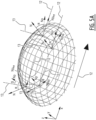
- Figure 5A shows a perspective view of part of a lens surface.
- This part could be the middle part of a diffractive optical element 4 as described above.
- the surface normal is drawn at multiple locations of the lens surface.
- This surface normal is drawn as an arrow with an uninterrupted line, and is indicated with reference sign N.
- the LC orientation in the off-state is, as explained above, a combination of the surface normal and the pre-tilt.
- the vector showing the LC orientation is also drawn at these multiple locations of the lens surface, and is indicated with reference sign Np.
- This LC orientation vector is drawn with interrupted dotted line.
- This LC orientation vector is directly related and intended to illustrate the orientation of the LC molecules in the off state.
- the pretilt angle is illustrated as angle ⁇ , being the angle between the surface normal N and the LC orientation vector Np.
- the effective tilt angle ⁇ is determining for the direction of orientation of the LC molecules when the lens is activated.
- the effect of the effective tilt angle ⁇ on the direction of orientation of the LC molecules can be best explained by projecting the LC orientation vector Np onto a surface parallel to the first electrode layer.
- the alignment direction 12 is typically defined parallel to the first electrode layer. Projections of the LC orientation vector Np onto this surface are shown in figure 5 and indicated with reference sign Npxy.
- the projection Npxy comprises a component parallel to the alignment direction 12 and a component transverse to the alignment direction 12. It is noted that the transverse component can be 0, depending on the location on the lens surface. In particular when the sloped surface is not sloped in a direction transverse to the alignment direction, the transverse component of the projection Npxy is 0.
- an angle ⁇ is used to illustrate the angle between the projection Npxy and the alignment direction 12. Test have shown that a reliable and predictable operation of the lens device can be guaranteed when, over substantially the whole alignment surface, ⁇ is smaller than 60 degrees, more preferably smaller than 45 degrees and most preferably smaller than 30 degrees. Based on the explanation above and the corresponding figures, the skilled person will realize that the angle ⁇ can be made smaller by increasing the pretilt and/or by reducing the slope angles.
- Figure 5B shows the same lens surface in a top view, parallel to the first electrode layer, and shows the same arrows that are shown in figure 5A .
- figure 5B shows the projections of the LC molecules on the first electrode layer Npxy.
- Figure 5B also shows the surface normal N.
- the angle ⁇ can be clearly seen.
- the angle ⁇ is 0.
- the angle ⁇ is about 30 degrees.
- Figure 5C shows the same lens surface in a side-view, also showing the same arrows that are shown in figures 5A and 5B . From figure 5C , it is clear that the effective tilt angles ⁇ are such that all LC orientation vector Np point to the right hand side of the figure. As a result, the LC orientation vectors Np all have a positive vector component in the alignment direction. The skilled person will directly recognize that the effect of these vectors all pointing to the right hand side of the figure is that the LC molecules will orient towards the right hand side when they are activated. This creates a uniform reaction of the LC molecules when activated which is, as described above, advantageous.
- Figure 6 shows a figure similar to figure 5A , but wherein the lens surface comprises two segments.
- the arrows in figure 6 are analogue to the arrows in figure 5 , described above.
- the pretilt is different in the two segments such that the alignment direction of one segment is parallel to and opposite to the alignment direction in the other segment.
- the alignment direction 12a at the right hand side of the lens surface of figure 6 , points to the right.
- the alignment direction 12b at the left hand side of the lens surface of figure 6 , points to the left.
- the absolute pretilt can be significantly smaller when the lens surface is segmented, to compensate for the slope angle of the lens surface. From figure 6 , it will be clear to the skilled person that the majority of the surface normal will show at least a vector component in the alignment direction. The pretilt largely aims at compensating for the influence of the vector components in other directions than the alignment direction so that their influence is reduced when activating the LC molecules.
- Figure 7 shows multiple segmentation options for lens surfaces, wherein multiple alignment directions and/or pretilts can be assigned to the multiple segments.
- the arrows illustrate the alignment direction while the interrupted lines illustrate the segmentation of the lens.
- Figure 7A shows a lens surface with only a single segment hence having only a single alignment direction.
- Figure 7a corresponds with the embodiment shown in figure 5 .
- Figure 7B shows a lens surface with two segments corresponding to the embodiment of figure 6 . The two segments are provided with opposite alignment directions.
- the molecules in the segments at the side of the lens have the largest transverse component with respect to the alignment direction due to the local slope.
- the outer segments can be provided with a larger pretilt angle. This might come at the expense of worse index matching in the off-state, but will lead to better optical performance in the on-state.
- the boundary between the inner and the outer segments can have more complex shapes other than a parallel line with the alignment direction and can be designed according to specific desired optical quality measures. Such segmentation is illustrated in figure 7C .
- Such a configuration can be even further combined with a central division with parallel, but opposing alignment directions.
- An example of such configuration is illustrated in figure 7D .
- a large central disclination line is imposed by design, but the off-axis deviations are minimized at the sides, while the effective tilt angle and the pretilt angle are largely in the same direction.
Landscapes
- Physics & Mathematics (AREA)
- Nonlinear Science (AREA)
- Optics & Photonics (AREA)
- General Physics & Mathematics (AREA)
- Chemical & Material Sciences (AREA)
- Crystallography & Structural Chemistry (AREA)
- Mathematical Physics (AREA)
- Spectroscopy & Molecular Physics (AREA)
- Health & Medical Sciences (AREA)
- Ophthalmology & Optometry (AREA)
- General Health & Medical Sciences (AREA)
- Liquid Crystal (AREA)
- Eyeglasses (AREA)
Claims (11)
- Eine polarisationsunabhängig abstimmbare Linse, aufweisend einen Aufbau aus einer ersten optischen Vorrichtung und einer zweiten optischen Vorrichtung, wobei zumindest die erste optische Vorrichtung aufweist:- eine erste Elektrodenschicht (8);- eine von der ersten Elektrodenschicht (8) in einem Abstand (d) angeordnete zweite Elektrodenschicht (9), wobei die erste und die zweite Elektrodenschicht (8, 9) lichtdurchlässig sind, wobei sich die erste Elektrodenschicht (8) zu der zweiten Elektrodenschicht (9) im Wesentlichen parallel erstreckt und wobei der durch beide Schichten gebildete Zwischenraum aufweist:- ein an zur ersten Elektrodenschicht (8) benachbartes diffraktives optisches Element (4) in Form einer Fresnel-Linsenstruktur mit einer ersten geneigten Oberfläche (11) im Zentrum der Fresnel-Linsenstruktur, welche von einer Mehrzahl an ringförmigen, weiteren geneigten Oberflächen umgeben ist, wobei die erste und die weiteren geneigten Oberflächen relativ zu der ersten Elektrodenschicht (8) jeweils einen Neigungswinkel aufweisen und mit einer ersten Ausrichtungsschicht bedeckt sind;- eine weitere Ausrichtungsschicht, die benachbart zu der zweiten Elektrode (9) angeordnet ist;- ein flüssigkristallines Material (10), das den Raum (7) zwischen der ersten Ausrichtungsschicht auf der ersten und den weiteren geneigten Oberflächen und der zur zweiten Elektrodenschicht (9) angrenzenden weiteren Ausrichtungsschicht ausfüllt und flüssigkristalline LC-Moleküle aufweist, die in einem ausgeschalteten Zustand, in dem kein elektrisches Feld an das flüssigkristalline Material (10) angelegt ist, vertikal ausgerichtet sind;wobei die LC-Moleküle an der Grenzfläche zu der ersten Ausrichtungsschicht eine Vorneigung mit zumindest einem applizierten Vorneigungswinkel (α) in zumindest einer Ausrichtungsrichtung (12) und einem absoluten Neigungswinkel (β) aufweisen, wobei der applizierte Vorneigungswinkel (α) an einer Stelle eines LC-Moleküls auf der geneigten Oberfläche relativ zur Normalen der geneigten Oberfläche gemessen wird, und der absolute Neigungswinkel (β) relativ zur Normalen der ersten Elektrodenschicht gemessen wird, und wobei die weitere Ausrichtungsschicht zur Ausrichtung in einer zur Ausrichtungsrichtung antiparallelen Richtung vorbehandelt wurde;wobei der zumindest eine applizierte Vorneigungswinkel (α) größer ist als der Neigungswinkel und auf diese Weise den Neigungswinkel der ersten und der weiteren geneigten Oberflächen kompensiert, indem im Wesentlichen alle LC-Moleküle in einem eingeschalteten Zustand, in dem ein elektrisches Feld an das flüssigkristalline Material (10) angelegt wird, so ausgerichtet werden, dass die Projektionen (Npxy) der LC-Moleküle (Np) auf die erste Elektrodenschicht (8) einen Winkel (θ) quer zur Ausrichtungsrichtung (12) innerhalb eines Bereichs von 60 Grad zur Ausrichtungsrichtung einschließen.
- Die abstimmbare Linse nach Anspruch 1, wobei die Fresnel-Linsenstruktur einen Durchmesser von 15 bis 35 mm aufweist.
- Die abstimmbare Linse nach einem der vorherigen Ansprüche, wobei der applizierte Vorneigungswinkel (α) den Neigungswinkel kompensiert, so dass der Winkel (Θ) quer zur Ausrichtungsrichtung (12) innerhalb eines Bereichs von 45 Grad zur Ausrichtungsrichtung (12) zu liegen kommt, vorzugsweise innerhalb eines Bereichs von 30 Grad, und/oder wobei der applizierte Vorneigungswinkel (α) im Wesentlichen gleichmäßig über die erste optische Vorrichtung verteilt ist.
- Die abstimmbare Linse nach einem der vorherigen Ansprüche, wobei die Ausrichtungsschicht auf zumindest einer der geneigten Oberflächen in zumindest ein inneres Segment sowie äußere Segmente unterteilt ist, wobei die inneren und äußeren Segmente parallel zur ersten Ausrichtungsrichtung angeordnet sind, wobei die Segmente mit der Ausrichtungsrichtung ausgerichtet sind, wobei die äußeren Segmente einen Vorneigungswinkel (α) aufweisen, der größer ist als der des zumindest einen inneren Segments.
- Die abstimmbare Linse nach einem der vorherigen Ansprüche, wobei sich die ringförmigen geneigten Oberflächen jeweils innerhalb einer aus der ersten Elektrodenschicht herausragenden Blende erstrecken, wobei die Blende ferner eine Seitenwand aufweist, die sich im Wesentlichen quer zur ersten Elektrodenschicht (8) erstreckt, wobei die erste Ausrichtungsschicht gemäß einem vordefinierten Muster vorgesehen ist, so dass die Seitenwände der Blenden frei gehalten werden und keine Ausrichtungsschicht aufweisen.
- Die abstimmbare Linse nach einem der vorherigen Ansprüche, wobei auf dem diffraktiven optischen Element (4) zwischen dessen geneigten Oberflächen (11) und der zweiten Elektrodenschicht (9) mehrere Abstandshalter (5) vorgesehen sind.
- Die abstimmbare Linse nach einem der vorherigen Ansprüche, wobei die zweite optische Vorrichtung mit der ersten optischen Vorrichtung identisch ist, wobei die erste und die zweite optische Vorrichtung vorzugsweise in umgekehrter Ausrichtung so zusammengefügt sind, dass der Abstand zwischen den zweiten Elektrodenschichten (9) geringer ist als der Abstand zwischen den ersten Elektrodenschichten (8) und/oder wobei die zweite optische Vorrichtung einen Polarisator darstellt.
- Die abstimmbare Linse nach einem der vorherigen Ansprüche, wobei die erste optische Vorrichtung eine Dioptrie-Stärke im Bereich von 0 bis +4, vorzugsweise zwischen +0,5 und 3,0, besonders bevorzugt zwischen +1,0 und 2,5, aufweist.
- Eine Brille mit einer polarisationsunabhängig abstimmbaren Linse nach einem der vorherigen Ansprüche.
- Verfahren zur Herstellung einer polarisationsunabhängig abstimmbaren Linse nach einem der vorherigen Ansprüche 1 bis 8, wobei das Verfahren das Applizieren einer Vorneigung umfasst, so dass die LC-Moleküle an einer Grenzfläche mit der Ausrichtungsschicht eine Vorneigung mit zumindest einem applizierten Vorneigungswinkel (α) in zumindest einer Ausrichtungsrichtung (12) aufweisen, sowie einen absoluten Neigungswinkel (β), wobei der applizierte Vorneigungswinkel (α) an einer Stelle eines LC-Moleküls auf der geneigten Oberfläche relativ zur Normalen der geneigten Oberfläche gemessen wird, und der absolute Neigungswinkel (β) relativ zur Normalen der ersten Elektrodenschicht (8) gemessen wird,
wobei der applizierte Vorneigungswinkel (α) größer ist als der Neigungswinkel und damit den Neigungswinkel der zumindest einen geneigten Oberfläche kompensiert, indem im Wesentlichen alle LC-Moleküle so ausgerichtet werden, dass in einem eingeschalteten Zustand, in dem ein elektrisches Feld an das flüssigkristalline Material (10) angelegt wird, die Projektionen (Npxy) der LC-Moleküle (Np) auf die erste Elektrodenschicht (8) einen Winkel (Θ) quer zur Ausrichtungsrichtung (12) innerhalb eines Bereichs von 60 Grad zur Ausrichtungsrichtung einschließen. - Verfahren nach Anspruch 10, wobei der Schritt des Applizierens der Vorneigung (α) das Reiben der ersten optischen Vorrichtung in der Ausrichtungsrichtung oder die Verwendung lichtempfindlicher Ausrichtungsmaterialien umfasst, wobei die Herstellung der ersten optischen Vorrichtung die folgenden Schritte aufweist:- Bereitstellen eines ersten Substrats (2) mit der ersten Elektrode (8), der Fresnel-Linsenstruktur und der ersten Ausrichtungsschicht;- Applizieren der Vorneigung mit zumindest einem applizierten Vorneigungswinkel (α) auf die erste Ausrichtungsschicht in der zumindest einen Ausrichtungsrichtung;- Bereitstellen eines zweiten Substrats (3) mit der zweiten Elektrode (9) und der weiteren Ausrichtungsschicht sowie Applizieren einer Vorneigung auf die weitere Ausrichtungsschicht in einer zur ersten Ausrichtungsrichtung antiparallelen Ausrichtung;- Zusammenfügen des ersten und des zweiten Substrats (2, 3) und Vorsehen von flüssigkristallinem Material (10) derart, dass ein beim Zusammenfügen gebildeter Raum (7) zwischen der ersten Ausrichtungsschicht und der weiteren Ausrichtungsschicht mit dem flüssigkristallinen Material (10) gefüllt wird.
Applications Claiming Priority (2)
| Application Number | Priority Date | Filing Date | Title |
|---|---|---|---|
| EP17187777.2A EP3447567B1 (de) | 2017-08-24 | 2017-08-24 | Optische vorrichtung mit flüssigkristallausrichtung |
| PCT/EP2018/072922 WO2019038439A1 (en) | 2017-08-24 | 2018-08-24 | OPTICAL DEVICE WITH ALIGNMENT OF LIQUID CRYSTALS |
Publications (3)
| Publication Number | Publication Date |
|---|---|
| EP3673327A1 EP3673327A1 (de) | 2020-07-01 |
| EP3673327C0 EP3673327C0 (de) | 2023-12-20 |
| EP3673327B1 true EP3673327B1 (de) | 2023-12-20 |
Family
ID=59745204
Family Applications (2)
| Application Number | Title | Priority Date | Filing Date |
|---|---|---|---|
| EP17187777.2A Active EP3447567B1 (de) | 2017-08-24 | 2017-08-24 | Optische vorrichtung mit flüssigkristallausrichtung |
| EP18755850.7A Active EP3673327B1 (de) | 2017-08-24 | 2018-08-24 | Polarisationsunabhängige abstimmbare linse und verfahren zu ihrer herstellung |
Family Applications Before (1)
| Application Number | Title | Priority Date | Filing Date |
|---|---|---|---|
| EP17187777.2A Active EP3447567B1 (de) | 2017-08-24 | 2017-08-24 | Optische vorrichtung mit flüssigkristallausrichtung |
Country Status (8)
| Country | Link |
|---|---|
| US (1) | US11409156B2 (de) |
| EP (2) | EP3447567B1 (de) |
| JP (1) | JP7384785B2 (de) |
| KR (1) | KR102681067B1 (de) |
| CN (1) | CN111213085B (de) |
| ES (2) | ES2955839T3 (de) |
| TW (1) | TWI815818B (de) |
| WO (1) | WO2019038439A1 (de) |
Families Citing this family (10)
| Publication number | Priority date | Publication date | Assignee | Title |
|---|---|---|---|---|
| CN112068332B (zh) * | 2019-06-11 | 2021-09-24 | 京东方科技集团股份有限公司 | 液晶镜片以及液晶眼镜 |
| RU2719341C1 (ru) * | 2019-09-09 | 2020-04-17 | Самсунг Электроникс Ко., Лтд. | Жидкокристаллическая линза с перестраиваемым фокусом |
| JP7826290B2 (ja) | 2020-08-31 | 2026-03-09 | アルファマイクロン インコーポレイテッド | グラデーション付き電気光学デバイス |
| NL2026764B1 (en) * | 2020-10-26 | 2022-06-17 | Morrow N V | Optical device with electroactive lens |
| CN114675463B (zh) * | 2020-12-26 | 2025-03-25 | 昆山暨扬光电科技有限公司 | 一种彩色成像透镜、制备方法及成像系统 |
| US12092906B2 (en) * | 2021-01-29 | 2024-09-17 | Coopervision International Limited | Flexible liquid crystal-containing lenses |
| EP4057057B1 (de) * | 2021-03-11 | 2024-12-25 | IMEC vzw | Elektrooptische komponente |
| US12001119B2 (en) * | 2021-10-19 | 2024-06-04 | Coopervision International Limited | Flexible liquid crystal-containing lenses |
| US12560746B2 (en) | 2022-09-15 | 2026-02-24 | Meta Platforms Technologies, Llc | Bi-cylindrical piezoelectric actuated optical lens |
| WO2025176715A1 (en) * | 2024-02-20 | 2025-08-28 | Flexenable Technology Limited | A device, optical lens, headset and system comprising liquid crystal material controllable by electrical elements |
Family Cites Families (31)
| Publication number | Priority date | Publication date | Assignee | Title |
|---|---|---|---|---|
| US6512563B1 (en) * | 1999-09-27 | 2003-01-28 | Citizen Watch Co., Ltd. | Method for producing ultrahigh resolution optical device panel |
| US7102602B2 (en) | 2001-09-18 | 2006-09-05 | Alphamicron, Inc. | Doubly curved optical device for eyewear and method for making the same |
| GB2403814A (en) * | 2003-07-10 | 2005-01-12 | Ocuity Ltd | Directional display apparatus with birefringent lens structure |
| JP4720507B2 (ja) * | 2004-02-03 | 2011-07-13 | 旭硝子株式会社 | 液晶レンズ素子および光ヘッド装置 |
| US7929094B2 (en) * | 2004-04-22 | 2011-04-19 | Sharp Kabushiki Kaisha | Vertically-aligned liquid crystal display device having a rugged structure which is in contact with the liquid crystal layer |
| JP2007065013A (ja) * | 2005-08-29 | 2007-03-15 | Seiko Epson Corp | 液晶装置及びその製造方法、並びに電子機器 |
| US20070216851A1 (en) * | 2006-03-01 | 2007-09-20 | Citizen Watch Co., Ltd. | Liquid crystal lens and imaging lens device |
| JP5037149B2 (ja) * | 2006-03-01 | 2012-09-26 | シチズンホールディングス株式会社 | 撮像レンズ装置 |
| AR064986A1 (es) | 2007-01-22 | 2009-05-06 | Pixeloptics Inc | Material cristalino liquido colesterico en lente electroactiva |
| JP5205077B2 (ja) * | 2008-02-22 | 2013-06-05 | シチズンホールディングス株式会社 | 液晶光学素子 |
| WO2009131925A2 (en) * | 2008-04-24 | 2009-10-29 | The Hong Kong University Of Science And Technology | Low voltage liquid crystal lens with a variable focal length |
| KR101689817B1 (ko) * | 2008-06-21 | 2017-01-09 | 렌즈벡터 인코퍼레이티드 | 효과적인 전극 구조의 동적 재구성을 사용하는 전자 광학 장치 |
| US8149377B2 (en) * | 2008-06-22 | 2012-04-03 | Lensvector Inc. | Tunable-focusing liquid crystal lens cell and method of fabrication thereof |
| JP2010091828A (ja) * | 2008-10-09 | 2010-04-22 | Citizen Holdings Co Ltd | 液晶光学素子とその製造方法 |
| WO2010102295A1 (en) | 2009-03-06 | 2010-09-10 | The Curators Of The University Of Missouri | Adaptive lens for vision correction |
| JP5383601B2 (ja) * | 2009-07-06 | 2014-01-08 | シチズンホールディングス株式会社 | 液晶レンズ |
| EP2530511B1 (de) * | 2010-01-29 | 2015-11-25 | Citizen Holdings Co., Ltd. | Verfahren zur herstellung elektronischer brillen und flüssigkristalllinsen |
| JP2012173534A (ja) * | 2011-02-22 | 2012-09-10 | Stanley Electric Co Ltd | 液晶光学素子及び液晶光学素子の製造方法 |
| CN102819143B (zh) * | 2011-06-10 | 2014-12-10 | 京东方科技集团股份有限公司 | 液晶盒及其制备方法 |
| US9709829B2 (en) * | 2011-11-18 | 2017-07-18 | Vuzix Corporation | Beam steering device |
| CN102650792A (zh) * | 2012-02-20 | 2012-08-29 | 京东方科技集团股份有限公司 | 液晶透镜及其制造方法、制造设备和3d显示装置 |
| JP5297551B1 (ja) * | 2012-07-06 | 2013-09-25 | 株式会社東芝 | 液晶光学素子および画像表示装置 |
| EP2963503B1 (de) * | 2013-03-01 | 2020-05-20 | Citizen Watch Co., Ltd. | Lichtstromteilungselement |
| KR20150081102A (ko) * | 2014-01-03 | 2015-07-13 | 삼성디스플레이 주식회사 | 액정 렌즈 패널 및 이를 포함하는 표시 장치 |
| JP2016018126A (ja) * | 2014-07-09 | 2016-02-01 | 株式会社東芝 | 液晶レンズ装置及び画像表示装置 |
| KR20160108756A (ko) * | 2015-03-06 | 2016-09-20 | 삼성디스플레이 주식회사 | 액정 렌즈 패널 및 그 구동 방법 |
| US9335569B1 (en) * | 2015-03-23 | 2016-05-10 | Northrop Grumman Systems Corporation | Tunable-focus thin electronic lens |
| TW201734605A (zh) * | 2016-03-18 | 2017-10-01 | 友達光電股份有限公司 | 陣列基板以及曲面液晶顯示面板 |
| CN205485200U (zh) * | 2016-03-31 | 2016-08-17 | 上海天马微电子有限公司 | 一种液晶显示面板及其显示装置 |
| ES2854025T3 (es) * | 2016-06-10 | 2021-09-20 | Morrow N V | Un dispositivo óptico termoplástico |
| JP6603806B2 (ja) | 2016-07-19 | 2019-11-06 | シャープ株式会社 | 液晶パネル、及び走査アンテナ |
-
2017
- 2017-08-24 ES ES17187777T patent/ES2955839T3/es active Active
- 2017-08-24 EP EP17187777.2A patent/EP3447567B1/de active Active
-
2018
- 2018-08-24 KR KR1020207008545A patent/KR102681067B1/ko active Active
- 2018-08-24 ES ES18755850T patent/ES2971467T3/es active Active
- 2018-08-24 JP JP2020511193A patent/JP7384785B2/ja active Active
- 2018-08-24 CN CN201880066770.2A patent/CN111213085B/zh active Active
- 2018-08-24 EP EP18755850.7A patent/EP3673327B1/de active Active
- 2018-08-24 US US16/641,437 patent/US11409156B2/en active Active
- 2018-08-24 WO PCT/EP2018/072922 patent/WO2019038439A1/en not_active Ceased
- 2018-08-24 TW TW107129600A patent/TWI815818B/zh active
Also Published As
| Publication number | Publication date |
|---|---|
| EP3673327C0 (de) | 2023-12-20 |
| US20200201112A1 (en) | 2020-06-25 |
| ES2971467T3 (es) | 2024-06-05 |
| JP7384785B2 (ja) | 2023-11-21 |
| TW201917468A (zh) | 2019-05-01 |
| ES2955839T3 (es) | 2023-12-07 |
| EP3447567C0 (de) | 2023-07-12 |
| CN111213085B (zh) | 2023-08-22 |
| WO2019038439A1 (en) | 2019-02-28 |
| TWI815818B (zh) | 2023-09-21 |
| KR20200040865A (ko) | 2020-04-20 |
| EP3447567B1 (de) | 2023-07-12 |
| JP2020531909A (ja) | 2020-11-05 |
| EP3447567A1 (de) | 2019-02-27 |
| CN111213085A (zh) | 2020-05-29 |
| KR102681067B1 (ko) | 2024-07-03 |
| EP3673327A1 (de) | 2020-07-01 |
| US11409156B2 (en) | 2022-08-09 |
Similar Documents
| Publication | Publication Date | Title |
|---|---|---|
| EP3673327B1 (de) | Polarisationsunabhängige abstimmbare linse und verfahren zu ihrer herstellung | |
| US8319937B2 (en) | Alignment of liquid crystalline materials to surface relief diffractive structures | |
| US11366340B2 (en) | Liquid crystal cell, method of driving liquid crystal cell, and liquid-crystal-based spectacle lens | |
| US9001282B2 (en) | Variable power optical element | |
| US10108068B2 (en) | Liquid crystal lens with variable focal length | |
| AU2021245170C1 (en) | Flexible, adjustable lens power liquid crystal cells and lenses | |
| CN117280254A (zh) | 具有电活性透镜的光学装置 | |
| CA2971624A1 (en) | Methods for forming variable optic ophthalmic devices including shaped liquid crystal elements | |
| JP2011099999A (ja) | 液晶光学デバイス | |
| Hirankittiwong et al. | Tunable Focusing Liquid Crystal Lenses: The Challenges and the Opportunities | |
| CN109696777B (zh) | 偏振无关液晶相位调制器 | |
| US20180341128A1 (en) | Liquid crystal optical element and optical apparatus | |
| CN115145085A (zh) | 液晶透镜结构 | |
| JP2018197847A (ja) | 液晶光学素子およびそれを有する光学機器 |
Legal Events
| Date | Code | Title | Description |
|---|---|---|---|
| STAA | Information on the status of an ep patent application or granted ep patent |
Free format text: STATUS: UNKNOWN |
|
| STAA | Information on the status of an ep patent application or granted ep patent |
Free format text: STATUS: THE INTERNATIONAL PUBLICATION HAS BEEN MADE |
|
| PUAI | Public reference made under article 153(3) epc to a published international application that has entered the european phase |
Free format text: ORIGINAL CODE: 0009012 |
|
| STAA | Information on the status of an ep patent application or granted ep patent |
Free format text: STATUS: REQUEST FOR EXAMINATION WAS MADE |
|
| 17P | Request for examination filed |
Effective date: 20200324 |
|
| AK | Designated contracting states |
Kind code of ref document: A1 Designated state(s): AL AT BE BG CH CY CZ DE DK EE ES FI FR GB GR HR HU IE IS IT LI LT LU LV MC MK MT NL NO PL PT RO RS SE SI SK SM TR |
|
| AX | Request for extension of the european patent |
Extension state: BA ME |
|
| RAP1 | Party data changed (applicant data changed or rights of an application transferred) |
Owner name: MORROW N.V. |
|
| DAV | Request for validation of the european patent (deleted) | ||
| DAX | Request for extension of the european patent (deleted) | ||
| STAA | Information on the status of an ep patent application or granted ep patent |
Free format text: STATUS: EXAMINATION IS IN PROGRESS |
|
| 17Q | First examination report despatched |
Effective date: 20220328 |
|
| GRAP | Despatch of communication of intention to grant a patent |
Free format text: ORIGINAL CODE: EPIDOSNIGR1 |
|
| STAA | Information on the status of an ep patent application or granted ep patent |
Free format text: STATUS: GRANT OF PATENT IS INTENDED |
|
| INTG | Intention to grant announced |
Effective date: 20230711 |
|
| GRAS | Grant fee paid |
Free format text: ORIGINAL CODE: EPIDOSNIGR3 |
|
| GRAA | (expected) grant |
Free format text: ORIGINAL CODE: 0009210 |
|
| STAA | Information on the status of an ep patent application or granted ep patent |
Free format text: STATUS: THE PATENT HAS BEEN GRANTED |
|
| AK | Designated contracting states |
Kind code of ref document: B1 Designated state(s): AL AT BE BG CH CY CZ DE DK EE ES FI FR GB GR HR HU IE IS IT LI LT LU LV MC MK MT NL NO PL PT RO RS SE SI SK SM TR |
|
| REG | Reference to a national code |
Ref country code: GB Ref legal event code: FG4D |
|
| REG | Reference to a national code |
Ref country code: CH Ref legal event code: EP |
|
| REG | Reference to a national code |
Ref country code: DE Ref legal event code: R096 Ref document number: 602018062920 Country of ref document: DE |
|
| P01 | Opt-out of the competence of the unified patent court (upc) registered |
Effective date: 20231212 |
|
| REG | Reference to a national code |
Ref country code: IE Ref legal event code: FG4D |
|
| U01 | Request for unitary effect filed |
Effective date: 20240118 |
|
| U07 | Unitary effect registered |
Designated state(s): AT BE BG DE DK EE FI FR IT LT LU LV MT NL PT SE SI Effective date: 20240227 |
|
| P04 | Withdrawal of opt-out of the competence of the unified patent court (upc) registered |
Effective date: 20240223 |
|
| PG25 | Lapsed in a contracting state [announced via postgrant information from national office to epo] |
Ref country code: GR Free format text: LAPSE BECAUSE OF FAILURE TO SUBMIT A TRANSLATION OF THE DESCRIPTION OR TO PAY THE FEE WITHIN THE PRESCRIBED TIME-LIMIT Effective date: 20240321 |
|
| PG25 | Lapsed in a contracting state [announced via postgrant information from national office to epo] |
Ref country code: GR Free format text: LAPSE BECAUSE OF FAILURE TO SUBMIT A TRANSLATION OF THE DESCRIPTION OR TO PAY THE FEE WITHIN THE PRESCRIBED TIME-LIMIT Effective date: 20240321 |
|
| PG25 | Lapsed in a contracting state [announced via postgrant information from national office to epo] |
Ref country code: RS Free format text: LAPSE BECAUSE OF FAILURE TO SUBMIT A TRANSLATION OF THE DESCRIPTION OR TO PAY THE FEE WITHIN THE PRESCRIBED TIME-LIMIT Effective date: 20231220 Ref country code: NO Free format text: LAPSE BECAUSE OF FAILURE TO SUBMIT A TRANSLATION OF THE DESCRIPTION OR TO PAY THE FEE WITHIN THE PRESCRIBED TIME-LIMIT Effective date: 20240320 Ref country code: HR Free format text: LAPSE BECAUSE OF FAILURE TO SUBMIT A TRANSLATION OF THE DESCRIPTION OR TO PAY THE FEE WITHIN THE PRESCRIBED TIME-LIMIT Effective date: 20231220 |
|
| REG | Reference to a national code |
Ref country code: ES Ref legal event code: FG2A Ref document number: 2971467 Country of ref document: ES Kind code of ref document: T3 Effective date: 20240605 |
|
| PG25 | Lapsed in a contracting state [announced via postgrant information from national office to epo] |
Ref country code: IS Free format text: LAPSE BECAUSE OF FAILURE TO SUBMIT A TRANSLATION OF THE DESCRIPTION OR TO PAY THE FEE WITHIN THE PRESCRIBED TIME-LIMIT Effective date: 20240420 |
|
| PG25 | Lapsed in a contracting state [announced via postgrant information from national office to epo] |
Ref country code: CZ Free format text: LAPSE BECAUSE OF FAILURE TO SUBMIT A TRANSLATION OF THE DESCRIPTION OR TO PAY THE FEE WITHIN THE PRESCRIBED TIME-LIMIT Effective date: 20231220 |
|
| PG25 | Lapsed in a contracting state [announced via postgrant information from national office to epo] |
Ref country code: SK Free format text: LAPSE BECAUSE OF FAILURE TO SUBMIT A TRANSLATION OF THE DESCRIPTION OR TO PAY THE FEE WITHIN THE PRESCRIBED TIME-LIMIT Effective date: 20231220 |
|
| PG25 | Lapsed in a contracting state [announced via postgrant information from national office to epo] |
Ref country code: SM Free format text: LAPSE BECAUSE OF FAILURE TO SUBMIT A TRANSLATION OF THE DESCRIPTION OR TO PAY THE FEE WITHIN THE PRESCRIBED TIME-LIMIT Effective date: 20231220 Ref country code: SK Free format text: LAPSE BECAUSE OF FAILURE TO SUBMIT A TRANSLATION OF THE DESCRIPTION OR TO PAY THE FEE WITHIN THE PRESCRIBED TIME-LIMIT Effective date: 20231220 Ref country code: RO Free format text: LAPSE BECAUSE OF FAILURE TO SUBMIT A TRANSLATION OF THE DESCRIPTION OR TO PAY THE FEE WITHIN THE PRESCRIBED TIME-LIMIT Effective date: 20231220 Ref country code: IS Free format text: LAPSE BECAUSE OF FAILURE TO SUBMIT A TRANSLATION OF THE DESCRIPTION OR TO PAY THE FEE WITHIN THE PRESCRIBED TIME-LIMIT Effective date: 20240420 Ref country code: CZ Free format text: LAPSE BECAUSE OF FAILURE TO SUBMIT A TRANSLATION OF THE DESCRIPTION OR TO PAY THE FEE WITHIN THE PRESCRIBED TIME-LIMIT Effective date: 20231220 |
|
| PG25 | Lapsed in a contracting state [announced via postgrant information from national office to epo] |
Ref country code: PL Free format text: LAPSE BECAUSE OF FAILURE TO SUBMIT A TRANSLATION OF THE DESCRIPTION OR TO PAY THE FEE WITHIN THE PRESCRIBED TIME-LIMIT Effective date: 20231220 |
|
| PG25 | Lapsed in a contracting state [announced via postgrant information from national office to epo] |
Ref country code: PL Free format text: LAPSE BECAUSE OF FAILURE TO SUBMIT A TRANSLATION OF THE DESCRIPTION OR TO PAY THE FEE WITHIN THE PRESCRIBED TIME-LIMIT Effective date: 20231220 |
|
| REG | Reference to a national code |
Ref country code: DE Ref legal event code: R097 Ref document number: 602018062920 Country of ref document: DE |
|
| U20 | Renewal fee for the european patent with unitary effect paid |
Year of fee payment: 7 Effective date: 20240827 |
|
| PLBE | No opposition filed within time limit |
Free format text: ORIGINAL CODE: 0009261 |
|
| STAA | Information on the status of an ep patent application or granted ep patent |
Free format text: STATUS: NO OPPOSITION FILED WITHIN TIME LIMIT |
|
| 26N | No opposition filed |
Effective date: 20240923 |
|
| P05 | Withdrawal of opt-out of the competence of the unified patent court (upc) changed |
Free format text: CASE NUMBER: APP_9661/2024 Effective date: 20240227 |
|
| REG | Reference to a national code |
Ref country code: CH Ref legal event code: PL |
|
| PG25 | Lapsed in a contracting state [announced via postgrant information from national office to epo] |
Ref country code: CH Free format text: LAPSE BECAUSE OF NON-PAYMENT OF DUE FEES Effective date: 20240831 Ref country code: MC Free format text: LAPSE BECAUSE OF FAILURE TO SUBMIT A TRANSLATION OF THE DESCRIPTION OR TO PAY THE FEE WITHIN THE PRESCRIBED TIME-LIMIT Effective date: 20231220 |
|
| PG25 | Lapsed in a contracting state [announced via postgrant information from national office to epo] |
Ref country code: IE Free format text: LAPSE BECAUSE OF NON-PAYMENT OF DUE FEES Effective date: 20240824 |
|
| U20 | Renewal fee for the european patent with unitary effect paid |
Year of fee payment: 8 Effective date: 20250827 |
|
| PGFP | Annual fee paid to national office [announced via postgrant information from national office to epo] |
Ref country code: ES Payment date: 20250901 Year of fee payment: 8 |
|
| PGFP | Annual fee paid to national office [announced via postgrant information from national office to epo] |
Ref country code: GB Payment date: 20250827 Year of fee payment: 8 |
|
| PG25 | Lapsed in a contracting state [announced via postgrant information from national office to epo] |
Ref country code: CY Free format text: LAPSE BECAUSE OF FAILURE TO SUBMIT A TRANSLATION OF THE DESCRIPTION OR TO PAY THE FEE WITHIN THE PRESCRIBED TIME-LIMIT; INVALID AB INITIO Effective date: 20180824 |
|
| PG25 | Lapsed in a contracting state [announced via postgrant information from national office to epo] |
Ref country code: HU Free format text: LAPSE BECAUSE OF FAILURE TO SUBMIT A TRANSLATION OF THE DESCRIPTION OR TO PAY THE FEE WITHIN THE PRESCRIBED TIME-LIMIT; INVALID AB INITIO Effective date: 20180824 |