EP3673766B1 - Meuble démontable à panneau et insert - Google Patents
Meuble démontable à panneau et insert Download PDFInfo
- Publication number
- EP3673766B1 EP3673766B1 EP19218839.9A EP19218839A EP3673766B1 EP 3673766 B1 EP3673766 B1 EP 3673766B1 EP 19218839 A EP19218839 A EP 19218839A EP 3673766 B1 EP3673766 B1 EP 3673766B1
- Authority
- EP
- European Patent Office
- Prior art keywords
- insert
- pin
- cover
- hole
- panel
- Prior art date
- Legal status (The legal status is an assumption and is not a legal conclusion. Google has not performed a legal analysis and makes no representation as to the accuracy of the status listed.)
- Active
Links
Images


Classifications
-
- A—HUMAN NECESSITIES
- A47—FURNITURE; DOMESTIC ARTICLES OR APPLIANCES; COFFEE MILLS; SPICE MILLS; SUCTION CLEANERS IN GENERAL
- A47B—TABLES; DESKS; OFFICE FURNITURE; CABINETS; DRAWERS; GENERAL DETAILS OF FURNITURE
- A47B47/00—Cabinets, racks or shelf units, characterised by features related to dismountability or building-up from elements
- A47B47/04—Cabinets, racks or shelf units, characterised by features related to dismountability or building-up from elements made mainly of wood or plastics
- A47B47/042—Panels connected without frames
-
- A—HUMAN NECESSITIES
- A47—FURNITURE; DOMESTIC ARTICLES OR APPLIANCES; COFFEE MILLS; SPICE MILLS; SUCTION CLEANERS IN GENERAL
- A47C—CHAIRS; SOFAS; BEDS
- A47C4/00—Foldable, collapsible or dismountable chairs
- A47C4/02—Dismountable chairs
- A47C4/021—Dismountable chairs connected by slotted joints
-
- E—FIXED CONSTRUCTIONS
- E05—LOCKS; KEYS; WINDOW OR DOOR FITTINGS; SAFES
- E05D—HINGES OR SUSPENSION DEVICES FOR DOORS, WINDOWS OR WINGS
- E05D7/00—Hinges or pivots of special construction
- E05D7/12—Hinges or pivots of special construction to allow easy detachment of the hinge from the wing or the frame
- E05D7/123—Hinges or pivots of special construction to allow easy detachment of the hinge from the wing or the frame specially adapted for cabinets or furniture
-
- F—MECHANICAL ENGINEERING; LIGHTING; HEATING; WEAPONS; BLASTING
- F16—ENGINEERING ELEMENTS AND UNITS; GENERAL MEASURES FOR PRODUCING AND MAINTAINING EFFECTIVE FUNCTIONING OF MACHINES OR INSTALLATIONS; THERMAL INSULATION IN GENERAL
- F16B—DEVICES FOR FASTENING OR SECURING CONSTRUCTIONAL ELEMENTS OR MACHINE PARTS TOGETHER, e.g. NAILS, BOLTS, CIRCLIPS, CLAMPS, CLIPS OR WEDGES; JOINTS OR JOINTING
- F16B12/00—Jointing of furniture or the like, e.g. hidden from exterior
- F16B12/10—Jointing of furniture or the like, e.g. hidden from exterior using pegs, bolts, tenons, clamps, clips, or the like
- F16B12/12—Jointing of furniture or the like, e.g. hidden from exterior using pegs, bolts, tenons, clamps, clips, or the like for non-metal furniture parts, e.g. made of wood, of plastics
- F16B12/20—Jointing of furniture or the like, e.g. hidden from exterior using pegs, bolts, tenons, clamps, clips, or the like for non-metal furniture parts, e.g. made of wood, of plastics using clamps, clips, wedges, sliding bolts, or the like
- F16B12/2009—Jointing of furniture or the like, e.g. hidden from exterior using pegs, bolts, tenons, clamps, clips, or the like for non-metal furniture parts, e.g. made of wood, of plastics using clamps, clips, wedges, sliding bolts, or the like actuated by rotary motion
-
- A—HUMAN NECESSITIES
- A47—FURNITURE; DOMESTIC ARTICLES OR APPLIANCES; COFFEE MILLS; SPICE MILLS; SUCTION CLEANERS IN GENERAL
- A47B—TABLES; DESKS; OFFICE FURNITURE; CABINETS; DRAWERS; GENERAL DETAILS OF FURNITURE
- A47B2230/00—Furniture jointing; Furniture with such jointing
- A47B2230/0074—Mortise and tenon joints or the like including some general male and female connections
- A47B2230/0092—Furniture assembled by mutually slotted joints
-
- E—FIXED CONSTRUCTIONS
- E05—LOCKS; KEYS; WINDOW OR DOOR FITTINGS; SAFES
- E05Y—INDEXING SCHEME ASSOCIATED WITH SUBCLASSES E05D AND E05F, RELATING TO CONSTRUCTION ELEMENTS, ELECTRIC CONTROL, POWER SUPPLY, POWER SIGNAL OR TRANSMISSION, USER INTERFACES, MOUNTING OR COUPLING, DETAILS, ACCESSORIES, AUXILIARY OPERATIONS NOT OTHERWISE PROVIDED FOR, APPLICATION THEREOF
- E05Y2900/00—Application of doors, windows, wings or fittings thereof
- E05Y2900/20—Application of doors, windows, wings or fittings thereof for furniture, e.g. cabinets
-
- F—MECHANICAL ENGINEERING; LIGHTING; HEATING; WEAPONS; BLASTING
- F16—ENGINEERING ELEMENTS AND UNITS; GENERAL MEASURES FOR PRODUCING AND MAINTAINING EFFECTIVE FUNCTIONING OF MACHINES OR INSTALLATIONS; THERMAL INSULATION IN GENERAL
- F16B—DEVICES FOR FASTENING OR SECURING CONSTRUCTIONAL ELEMENTS OR MACHINE PARTS TOGETHER, e.g. NAILS, BOLTS, CIRCLIPS, CLAMPS, CLIPS OR WEDGES; JOINTS OR JOINTING
- F16B12/00—Jointing of furniture or the like, e.g. hidden from exterior
- F16B12/10—Jointing of furniture or the like, e.g. hidden from exterior using pegs, bolts, tenons, clamps, clips, or the like
- F16B12/12—Jointing of furniture or the like, e.g. hidden from exterior using pegs, bolts, tenons, clamps, clips, or the like for non-metal furniture parts, e.g. made of wood, of plastics
- F16B12/20—Jointing of furniture or the like, e.g. hidden from exterior using pegs, bolts, tenons, clamps, clips, or the like for non-metal furniture parts, e.g. made of wood, of plastics using clamps, clips, wedges, sliding bolts, or the like
- F16B12/2009—Jointing of furniture or the like, e.g. hidden from exterior using pegs, bolts, tenons, clamps, clips, or the like for non-metal furniture parts, e.g. made of wood, of plastics using clamps, clips, wedges, sliding bolts, or the like actuated by rotary motion
- F16B2012/2072—Pin and drum securing devices; Drums having lever with cam surface to engage the head of the pin
Definitions
- the invention relates to removable panel furniture, panels and inserts for assembling such furniture.
- the furniture thus offered is designed to form a single element. It is therefore advantageous to provide a piece of furniture that can form different elements, such as a table, a chair, a cupboard, etc., with the same panels so as not to have to buy different pieces of furniture.
- One object of the invention is to provide a piece of furniture which is easy to assemble and which can be dismantled without tools.
- a panel of removable furniture comprising at least one notch located on at least one edge of the panel, each notch comprising two main faces facing each other and a secondary face facing an opening of the notch.
- Each main face has a longitudinal groove extending between the edge and the secondary face to receive a removable insert, and has a notch perpendicular to the longitudinal groove to hold the removable insert in the notch.
- a panel suitable for assembling removable furniture and more particularly a panel which can be assembled without tools.
- Such a panel makes it possible to create modular dismountable furniture to form different elements each having a distinct function. This offers the possibility of reducing the bulk of several pieces of furniture, by assembling the panels differently to create various pieces of furniture with varied functions.
- the panel may include several notches each having the same depth.
- the notches can be distributed over at least one edge of the panel with a constant distance between them.
- a removable insert of the connector type comprising two opposite tongues intended to be introduced into the two longitudinal grooves of at least one notch of a panel as defined above, at least one orifice for receiving a pin , and a cover pivotally mounted between an open position in which the pin can be inserted into the insert and the insert can be introduced into said at least one notch, and a closed position in which the pin is blocked in the insert and the cover is introduced into the notches of said at least one notch to hold the insert.
- Such an insert makes it possible to increase the number of possible combinations when assembling two panels together. Indeed, we can assemble the panels in the same plane, for example to obtain a larger panel, or connect them together perpendicularly, for example to create a closed piece of furniture.
- the insert may have a parallelepiped shape and in which a first orifice is located on a first face of the insert, and a second orifice is located on a second face of the insert adjacent to the first face and opposite a third face of the insert on which the cover is located.
- the cover may comprise two plates located respectively opposite the first and second orifices, each plate comprising a main through hole for receiving the pin when the cover is in the open position, and a secondary through hole opening into the main through hole of the plate to lock the pin when the cover is in the closed position.
- a removable piece of furniture comprising at least one panel as defined above.
- Such furniture is easy to disassemble because it does not require the use of tools. It allows you to modify the function of the piece of furniture, that is to say, to assemble different elements with the same panels to create, for example, a table, a chair, a cupboard, a bench, a desk... We make it easier also the storage of dismantled furniture.
- the piece of furniture may further comprise a removable insert of the square type having two square-shaped parts separated by a support plate introduced into at least one notch of at least one notch of said at least one panel.
- the piece of furniture may also include a removable insert of the pivot type having a "U" shaped body provided with a lug providing a pivot function, the body being introduced into at least one notch of at least one notch of said at least one panel .
- the piece of furniture may also include a removable insert of the connector type as defined above introduced into at least one notch of said at least one panel for mounting the piece of furniture.
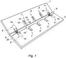
- each panel 1, 2 comprises at least one notch 4 to 8 located on a first edge 9 of the panel 1, 2.
- each panel 1, 2 has four edges.
- the panels can include several notches 4 to 8 located on their edges. Each notch 4 to 8 corresponds to a removal of a part of the panel 1, 2 carried out on an edge 9 of the panel, that is to say at the edge of the panel 1, 2.
- a notch 4 to 8 is intended to receive a removable insert 10 for mounting the panels 1, 2 between them so as to produce the removable piece of furniture 3.
- the notches 4 to 8 are also intended to receive particular removable inserts 17, 21, illustrated respectively in figures 2 and 3 .
- a notch 4 to 8 of a first panel 1 can receive another notch 4 to 8 of a second panel 2a for mounting the first panel 1 perpendicular to the second panel 2a, as illustrated in the Figure 14 .
- Each notch 4 to 8 has an opening 14, two main faces 11, 12 located facing each other, and a secondary face 13 located facing the opening 14, that is to say opposite to the opening 14.
- Each main face 11, 12 has a longitudinal groove 15 extending from the edge 9, where the notch is formed, to the secondary face 13.
- each main face 11, 12 has a notch 16 perpendicular to the longitudinal groove 15 of the main face 11, 12.
- the notches 16 are intended to hold the removable insert 10, 17, 21 in notch 4 to 8 when furniture 3 is assembled.
- each panel 1, 2, 2a includes several notches 4 to 8.
- each panel 1, 2 includes five notches 4 to 8.
- different pieces of furniture 3 can be produced, each having a distinct function, from the same set of panels 1, 2.
- the number of panels used to assemble these different pieces of furniture may vary from one piece of furniture to another.
- the notches 4 to 8 each have the same depth, in other words the lengths of all the longitudinal grooves 15 are equal. This makes it possible to introduce the same type of insert 10, 17, 21 into each of the notches 4 to 8, thus reducing the number of different inserts to be manufactured.
- notches 4 through 8 are all the same.
- the notches 4 to 8 are distributed over at least one edge 9 of a panel 1, 2 with a constant distance between them. This means that several identical panels can be made, which are simpler to manufacture.
- each panel 1, 2 can have notches 4 to 8 on its four edges.
- FIG. 2 there is shown a removable insert of the square type 17 having two square-shaped parts 18, 19 separated by a support plate 20 intended to be introduced into at least one notch 16 of at least one notch 4 to 8.
- This bracket type insert 17 makes it possible to stabilize the assembly of two panels 2, 2a perpendicular to each other, as illustrated in the Figure 14 . More particularly, the notches 16 of the notches 4 to 8 of at least one panel 1, 2, 2a all have the same width equal to that of the support plate 20.
- a removable insert of the pivot type 21 having a “U”-shaped body 22 provided with a lug 23, preferably cylindrical with a circular section, providing a pivot function.
- the body 22 of the pivot type insert 21 is intended to be introduced into at least one notch 16 of at least one notch 4 to 8.
- This pivot type insert 17 provides a pivot function for, in particular, receiving a mobile panel in order to mount an opening 24 to create a cabinet 3, as illustrated in the Figure 14 . More particularly, the notches 16 of the notches 4 to 8 of at least one panel 1, 2 all have the same width equal to that of the body 22 of the insert 21.
- a removable insert of the connector type 10 intended to be introduced into at least one notch 4 to 8.
- the insert of the connector type 10 can be connected to another insert of the connector type 10 located on another panel to assemble two panels together, as shown in the figures 1 And 13 .
- the connector type insert 10 can be connected to an accessory 25, for example a half-hinge as illustrated in the figure 1 , or a caster in order to provide a table on casters, ...
- the connector type inserts 10 are each connected to a half-hinge.
- the inserts 10 together form a hinge so that the panels 1, 2 can be movable relative to each other.
- the connector type insert 10 has a body 26 having a generally parallelepiped shape, preferably the shape of a rectangular parallelepiped.
- the insert 10 comprises two tongues 27, 28 located on two opposite side faces of the insert 10, at least one orifice 29, 30, and a cover 31.
- the tongues 27, 28 are intended to be introduced into the two longitudinal grooves 15 of a notch 4 to 8 of a panel 1, 2, 2a.
- the longitudinal grooves 15 then play the role of guiding the removable insert 10 in the notch 4 to 8.
- the orifices 29, 30 are intended to receive, one or the other, a pin 32.
- the pin 32 is a small part, preferably made of metal, which is introduced into the insert 10, passing through an orifice 29 , 30 so that the whole constitutes a rigid, removable assembly.
- the pin 32 comprises a cylindrical body and at least one slot 33, 34 located at each end of the pin 32 and intended to block the pin 32 in the removable insert of the connector type 10.
- the pin 32 has a single slot 33 located at one end, and the other end can be connected to an accessory 25, such as a half-hinge or a roller, etc.
- each orifice 29, 30 forms a passage for introducing the pin 32 into the insert 10.
- a first orifice 29 is located on a first face 35 of the insert 10 and a second orifice 30 is located on a second face 36 adjacent to the first face 35.
- the first face 35 is adjacent to the two lateral faces which carry the tongues 27, 28.
- the first two orifices 29 of the two inserts 10 make it possible to connect the two panels 1, 2 in the same plane, as illustrated in the Figure 14 , when a pin 32 is inserted into the first two orifices 29 of the two inserts 10.
- the second orifice 30 of the inserts 10 allows, for its part, to connect two panels perpendicular to each other.
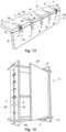
- the two panels 1, 2 are connected perpendicularly to each other, as illustrated in the figure 13 .
- the pin 32 is inserted into the second orifices 30 of the two inserts, the two panels 1, 2 are connected parallel to each other.
- the cover 31 is mounted on a third face 37 of the insert 10 opposite the second face 36.
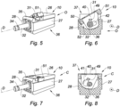
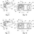
- the cover 31 is pivotally mounted on the body 26 of the insert 10, between an open position O, illustrated in figures 5, 6 And 9, 10 , and a closed position C, illustrated in figures 7, 8 And 11, 12 .
- a pin 32 can be inserted into the insert 10 and the insert 10 can be introduced into a notch 4 to 8 of a panel 1, 2, 2a.
- the closed position C the pin 32 which has been inserted into the insert 10 is blocked in the insert 10 and the cover 31 is inserted into the notches 16 of the notch 4 to 8 to hold the insert in the notch 4 to 8.
- the cover 31 comprises a first plate 40 fixedly mounted on an internal face of the cover 31.
- the first plate 40 is mounted perpendicular to the internal face of the cover 31 and perpendicular to a first axis D corresponding to a longitudinal axis of the insert 10.
- the first axis D also corresponds to the direction of introduction D of a pin 32 in the first orifice 29 of the insert 10.
- the first plate is mounted opposite of the first orifice 29.
- the first plate 40 comprises a first through hole 41 intended to receive one end of a pin 32, and a second through hole 42 intended to block the pin 32 in the insert 10.
- the first through hole 41 is also denoted main hole of the first plate 40 and the second through hole 42 is also denoted secondary hole of the first plate 40.
- the second through hole 42 opens partly into the first through hole 41.
- the diameter of the first through hole 41 is greater than that of the pin 32 so that it can pass through the first through hole 41, when the cover 31 is in the open position O.
- the diameter of the second through hole 42 is, for its part, greater than that of the slots 33, 34 of a pin 32, and lower than that of the body of the pin 32 to retain the pin 32 in the second through hole 42 when the cover 31 has pivoted into its closed position C.
- the first through hole 41 is located opposite the first orifice 29 of the insert 10, and a pin 32 can be introduced successively into the first orifice 29, then into the first through hole 41.
- the pin 32 is introduced until a slot 33 is located at the level of the first through hole 41.
- a stop can be provided in the insert 10 to correctly position the slot 33 at the level of the first through hole 41.
- the cover 31 is pivoted into its closed position C, by a rotation of the cover 31 around the first axis D.
- the rotation of the cover 31 causes a rotation of the first plate 40 around the first axis D, and causes the introduction of the second through hole 42 into the slot 33.
- the second through hole 42 opens partly into the first through hole 41, the second through hole 42 can be introduced into the slot 33.
- the opening located between the first and second through holes 41, 42 is greater than the diameter of the slots 33, 34 of the pin 32 to allow the second through hole 42 to be introduced, by rotation of the first plate 40, into a slot 33, 34 of the pin 32.
- the cover 31 is placed in the closed position C, the pin 32 is blocked in the insert 10.
- the cover 31 is pivoted into its open position O, which releases the second through hole 42 from the slot 33, in other words the first through hole 41 is again introduced into the slot 33 and the pin 32 can be extracted from the first through hole 41.
- the cover 31 can comprise a second plate 43 mounted movable in translation along a second axis E both perpendicular to the first axis D and perpendicular to a direction F of introducing a pin 32 into the second orifice 30 of the insert 10.
- the second plate 43 is mounted perpendicular to the direction F of introducing a pin 32 into the second orifice 30 of the insert 10.
- the second plate 43 is mounted opposite the second orifice 30.
- the second plate 43 comprises a third through hole 44 intended to receive one end of a pin 32, and a fourth hole through hole 45 intended to block the pin 32 in the insert 10.
- the third through hole 44 is also denoted main hole of the second plate 43 and the fourth through hole 45 is also denoted secondary hole of the second plate 43.
- the fourth through hole 45 opens partly into the third through hole 44.
- the diameter of the third through hole 44 is greater than that of the pin 32 so that it can pass through the third through hole 44, when the cover 31 is in the open position O.
- the diameter of the fourth through hole 45 is, for its part, greater than that of the slots 33, 34 of a pin 32, and less than that of the body of the pin 32 to retain the pin 32 in the fourth through hole 45 when the cover 31 has pivoted into its closed position C.
- the third through hole 44 is located opposite the second orifice 30 of the insert 10, and we can introduce a pin 32 successively into the second orifice 30, then into the third through hole 44.
- the pin 32 is introduced until a slot 33 is located at the level of the third through hole 44.
- the cover 31 is pivoted into its closed position C, by a rotation of the cover 31 around the first axis D. rotation of the cover 31 causes a translation of the second plate 43 along the second axis E, and causes the introduction of the fourth through hole 45 into the slot 33.
- the fourth through hole 45 opens partly into the third hole through 44, the fourth through hole 44 can be introduced into the slot 33.
- the opening located between the third and fourth through holes 44, 45 is greater than the diameter of the slots 33, 34 of the pin 32 to allow introduce, by translation of the second plate 43, the fourth through hole 45 into a slot 33, 34 of the pin 32.
- the second plate 43 comprises two lateral lugs 46, 47.
- a first lug 46 is introduced into a first hook 48 formed on the cover 31, and projecting from the internal face of the cover 31.
- the second lug 47 is introduced into a second hook 49 formed on the first plate 43, the second hook 49 corresponding to a recess which receives the second lug 47.
- the cover 31 of an insert 10 makes it possible to hold the insert 10 in position in a notch 4 to 8 of a panel 1, 2, 2a.
- the insert can be introduced into the notch 4 to 8 by sliding the tongues 27, 28 in the longitudinal grooves 15 of the notch 4 to 8, and in this case the side edges 50, 51 of the cover 31 do not interfere.
- a first lateral edge 50 of the cover 31 is entered into a housing 52 of the insert 10 to be placed at the level of the tongue 28 of the insert 10. In this position the first lateral edge 50 of the cover 31 does not prevent the introduction of the tongue 28 into a longitudinal groove 15.
- the second lateral edge 51 of the cover 31 is located outside the body 26 of the insert 10, and it does not hinder the introduction of the another tongue 27 in the other longitudinal groove 15 of the notch 4 to 8. Then, after having introduced the insert 10 into the notch 4 to 8, until it is in contact with the secondary face 13, the lateral edges 50, 51 are positioned opposite the notches 16 of the notch 4 to 8. When the cover 31 is pivoted in its closed position C, the side edges 50, 51 are introduced respectively into the notches 16 of the notch 4 to 8, as illustrated on the figures 1 And 13 .
- the connector type insert 10 once introduced into a notch 4 to 8, blocks the notch 4 to 8 so that elements do not pass between the insert 10 and the panel 1, 2, 2a.
- the connector type insert 10 may include an oblong hole 53 located on the second face 36 of the insert 10.
- the oblong hole 53 can receive a first end of a pin 32, for example the other end can be introduced into another insert, in order to be able to adjust the position of the pin 32 relative to the insert 10 having the oblong hole 53. It is thus possible to tilt the orientation of one panel relative to another to achieve, for example example, a back of a chair whose orientation is tiltable.
- FIG. 14 On the figures 14 to 16 , several embodiments of a removable piece of furniture 3 have been shown.
- a cabinet is shown with an opening panel 24, two pairs of side panels, each pair having two panels mechanically connected in the same plane.
- the cabinet 3 further comprises a panel 2a acting as a shelf and held to the pairs of panels by bracket type connectors 17.
- Figure 15 illustrates a table including a bench.
- Figure 16 illustrates a table.
- the invention which has just been described is particularly suitable for providing dismountable, modular furniture in order to produce furniture having different functions with the same elements, that is to say with the same panels and the same inserts.
- Such furniture has the advantage of can be easily assembled and disassembled without tools. This furniture is particularly robust once assembled.
Landscapes
- Engineering & Computer Science (AREA)
- Mechanical Engineering (AREA)
- General Engineering & Computer Science (AREA)
- Life Sciences & Earth Sciences (AREA)
- Wood Science & Technology (AREA)
- Furniture Connections (AREA)
Description
- L'invention concerne les meubles démontables à panneaux, les panneaux et inserts pour le montage de tels meubles.
- Actuellement, il existe des meubles démontables comprenant plusieurs panneaux indépendants qui sont assemblés pour monter un meuble spécifique, c'est-à-dire un meuble ayant une fonction particulière unique, comme une armoire, une table, une chaise... De manière générale les panneaux sont assemblés à l'aide d'outils, ce qui rend le montage des meubles plus difficile. Par ailleurs, des problèmes surviennent lors du démontage des panneaux car les pièces servant à fixer les panneaux s'usent et ne peuvent plus être utilisées pour un remontage du meuble. On peut citer le brevet américain
US 6174116 qui divulgue un système de panneaux emboîtables réglables pour assembler une unité modulaire, telle qu'une étagère ou une boîte. On peut également citer le brevet américainUS 3730568 qui divulgue un dispositif d'attache libérable pour des éléments de meubles. En outre, les meubles ainsi proposés sont conçus pour ne former qu'un seul et même élément. Il est donc avantageux de fournir un meuble qui puisse former différents éléments, tels une table, une chaise, une armoire, ..., avec les mêmes panneaux de manière à ne pas avoir à acheter différents meubles. - L'objet Un de l'invention consiste à fournir un meuble dont le montage est facilité et qui soit démontable sans outils.
- Selon un aspect de l'invention, il est proposé un panneau d'un meuble démontable, comprenant au moins une entaille située sur au moins un chant du panneau, chaque entaille comportant deux faces principales en regard l'une de l'autre et une face secondaire en regard d'une ouverture de l'entaille. Chaque face principale comporte une rainure longitudinale s'étendant entre le chant et la face secondaire pour recevoir un insert amovible, et comporte une encoche perpendiculaire à la rainure longitudinale pour maintenir l'insert amovible dans l'entaille.
- Ainsi on fournit un panneau adapté pour le montage d'un meuble démontable, et plus particulièrement un panneau qui puisse être monté sans outil. Un tel panneau permet de réaliser un meuble démontable modulaire pour former différents éléments ayant chacun une fonction distincte. On offre ainsi la possibilité de diminuer l'encombrement de plusieurs meubles, en assemblant différemment les panneaux pour réaliser divers meubles à fonctions variées.
- Le panneau peut comprendre plusieurs entailles ayant chacune une même profondeur.
- Les entailles peuvent être réparties sur au moins un chant du panneau avec un écart entre elles constant.
- Il est par ailleurs proposé un insert amovible du type connecteur, comprenant deux languettes opposées destinées à être introduites dans les deux rainures longitudinales d'au moins une entaille d'un panneau tel que défini ci-avant, au moins un orifice pour recevoir une goupille, et un couvercle monté pivotant entre une position ouverte dans laquelle la goupille peut être introduite dans l'insert et l'insert peut être introduit dans ladite au moins une entaille, et une position fermée dans laquelle la goupille est bloquée dans l'insert et le couvercle est introduit dans les encoches de ladite au moins une entaille pour maintenir l'insert.
- Un tel insert permet d'augmenter le nombre de combinaisons possibles lors de l'assemblage de deux panneaux entre eux. En effet, on peut assembler les panneaux dans un même plan, par exemple pour obtenir un panneau plus grand, ou les relier entre eux perpendiculairement, par exemple pour réaliser un meuble fermé.
- L'insert peut avoir une forme parallélépipédique et dans lequel un premier orifice est situé sur une première face de l'insert, et un deuxième orifice est situé sur une deuxième face de l'insert adjacente à la première face et opposée à une troisième face de l'insert sur laquelle est situé le couvercle.
- Le couvercle peut comprendre deux plaques situées respectivement en regard des premier et deuxième orifices, chaque plaque comprenant un trou traversant principal pour recevoir la goupille lorsque le couvercle est dans la position ouverte, et un trou traversant secondaire débouchant dans le trou traversant principal de la plaque afin de bloquer la goupille lorsque le couvercle est dans la position fermée.
- Il est ainsi proposé un meuble démontable comprenant au moins un panneau tel que défini ci-avant.
- Un tel meuble est facile à démonter car il ne nécessite pas d'utiliser des outils. Il permet de pouvoir modifier la fonction du meuble, c'est-à-dire de monter différents éléments avec les même panneaux pour réaliser, par exemple, une table, une chaise, une armoire, un banc, un bureau... On facilite également le rangement du meuble démonté.
- Le meuble peut comprendre en outre un insert amovible du type équerre ayant deux parties en forme d'équerre séparées par une plaque d'appui introduite dans au moins une encoche d'au moins une entaille dudit au moins un panneau.
- Le meuble peut également comprendre un insert amovible du type pivot ayant un corps en forme de « U » muni d'un ergot fournissant une fonction pivot, le corps étant introduit dans au moins une encoche d'au moins une entaille dudit au moins un panneau.
- Le meuble peut encore comprendre un insert amovible du type connecteur tel que défini ci-avant introduit dans au moins une entaille dudit au moins un panneau pour le montage du meuble.
- D'autres avantages et caractéristiques ressortiront plus clairement de la description qui va suivre de modes particuliers de réalisation de l'invention donnés à titre d'exemples non limitatifs et représentés aux dessins annexés, dans lesquels :
- La
figure 1 , illustre schématiquement une vue en perspective d'un panneau selon l'invention ; - les
figures 2 et 3 , illustrent schématiquement des vues en perspective de plusieurs inserts ; - la
figure 4 , illustre de façon schématique une vue en perspective éclatée d'un insert amovible du type connecteur ; - les
figures 5 et 6 , illustrent de façon schématique deux vues, respectivement en perspective et en coupe selon un plan transversal, de l'insert amovible du type connecteur où le couvercle est dans une position ouverte et une goupille est insérée dans un premier orifice de l'insert ; - les
figures 7 et 8 , illustrent de façon schématique deux vues, respectivement en perspective et en coupe selon un plan transversal, de l'insert amovible du type connecteur où le couvercle est dans une position fermée et une goupille est insérée dans un premier orifice de l'insert ; - les
figures 9 et 10 , illustrent de façon schématique deux vues, respectivement en perspective et en coupe selon un plan longitudinal, de l'insert amovible du type connecteur où le couvercle est dans une position ouverte et une goupille est insérée dans un deuxième orifice de l'insert ; - les
figures 11 et 12 , illustrent de façon schématique deux vues, respectivement en perspective et en coupe selon un plan longitudinal, de l'insert amovible du type connecteur où le couvercle est dans une position fermée et une goupille est insérée dans un deuxième orifice de l'insert ; - la
figure 13 , illustre de façon schématique une vue en perspective d'un mode d'assemblage de deux panneaux ; et - les
figures 14 à 16 , illustrent schématiquement des vues en perspective de différents modes de réalisation d'un meuble démontable. - Sur la
figure 1 , on a représenté deux panneaux 1, 2 d'un meuble démontable 3, dont des exemples de montage sont illustrés auxfigures 14 à 16 . Les panneaux 1, 2 ont une forme globalement parallélépipédique, en particulier une forme de parallélépipède rectangle. Les panneaux 1, 2 peuvent être en bois ou en plastique. On peut encore envisager de réaliser les panneaux 1, 2 en métal. Chaque panneau 1, 2 comprend au moins une entaille 4 à 8 située sur un premier chant 9 du panneau 1, 2. Dans sa forme parallélépipédique, chaque panneau 1, 2 comporte quatre chants. De façon générale, les panneaux peuvent comprendre plusieurs entailles 4 à 8 situées sur leurs chants. Chaque entaille 4 à 8 correspond à un enlèvement d'une partie du panneau 1, 2 effectué sur un chant 9 du panneau, c'est-à-dire au bord du panneau 1, 2. Une entaille 4 à 8 est destinée à recevoir un insert amovible 10pour le montage des panneaux 1, 2 entre eux de manière à réaliser le meuble démontable 3. Les entailles 4 à 8 sont également destinées à recevoir des inserts amovibles particuliers 17, 21, illustrés respectivement auxfigures 2 et 3 . Par exemple, une entaille 4 à 8 d'un premier panneau 1 peut recevoir une autre entaille 4 à 8 d'un deuxième panneau 2a pour un montage du premier panneau 1 perpendiculairement au deuxième panneau 2a, comme illustré sur lafigure 14 . Chaque entaille 4 à 8 comporte une ouverture 14, deux faces principales 11, 12 situées en regard l'une de l'autre, et une face secondaire 13 située en regard de l'ouverture 14, c'est-à-dire opposée à l'ouverture 14. Chaque face principale 11, 12 comporte une rainure longitudinale 15 s'étendant depuis le chant 9, où est formée l'entaille, jusqu'à la face secondaire 13. Les rainures longitudinales 15 sont destinées à recevoir un insert amovible 10, 17, 21. En outre, chaque face principale 11, 12 comporte une encoche 16 perpendiculaire à la rainure longitudinale 15 de la face principale 11, 12. Les encoches 16 sont destinées à maintenir l'insert amovible 10, 17, 21 dans l'entaille 4 à 8 lorsque le meuble 3 est monté. - Par exemple, chaque panneau 1, 2, 2a comprend plusieurs entailles 4 à 8. Dans le mode de réalisation illustré à la
figure 1 , chaque panneau 1, 2 comprend cinq entailles 4 à 8. Plus le nombre d'entailles augmente et plus le nombre de combinaisons possibles pour positionner un panneau par rapport à l'autre augmente. Ainsi, on peut réaliser différents meubles 3 ayant chacun une fonction distincte à partir d'un même ensemble de panneaux 1, 2. Le nombre des panneaux utilisés pour monter ces différents meubles pouvant varier d'un meuble à l'autre. De préférence les entailles 4 à 8 ont chacune une même profondeur, en d'autres termes les longueurs de toutes les rainures longitudinales 15 sont égales. Ce qui permet d'introduire un même type d'insert 10, 17, 21 dans chacune des entailles 4 à 8, on diminue ainsi le nombre d'inserts différents à fabriquer. Par exemple, les entailles 4 à 8 sont toutes identiques. Selon le mode de réalisation illustré à lafigure 1 , les entailles 4 à 8 sont réparties sur au moins un chant 9 d'un panneau 1, 2 avec un écart entre elles constant. Ainsi on peut réaliser plusieurs panneaux identiques, qui sont plus simples à fabriquer. En variante, chaque panneau 1, 2 peut avoir des entailles 4 à 8 sur ses quatre chants. - Sur les
figures 2 et 3 , on a représenté deux inserts 17, 21 amovibles pour le montage des panneaux 1, 2. - Sur la
figure 2 , on a représenté un insert amovible du type équerre 17 ayant deux parties 18, 19 en forme d'équerre séparées par une plaque d'appui 20 destinée à être introduite dans au moins une encoche 16 d'au moins une entaille 4 à 8. Cet insert du type équerre 17 permet de stabiliser l'assemblage de deux panneaux 2, 2a perpendiculaires entre eux, comme illustré sur lafigure 14 . Plus particulièrement, les encoches 16 des entailles 4 à 8 d'au moins un panneau 1, 2, 2a ont toutes une même largeur égale a celle de la plaque d'appui 20. - Sur la
figure 3 , on a représenté un insert amovible du type pivot 21 ayant un corps 22 en forme de « U » muni d'un ergot 23, de préférence cylindrique à section circulaire, fournissant une fonction pivot. Le corps 22 de l'insert du type pivot 21 est destiné à être introduit dans au moins une encoche 16 d'au moins une entaille 4 à 8. Cet insert du type pivot 17 fournit une fonction pivot pour, notamment, recevoir un panneau mobile afin de monter un ouvrant 24 pour réaliser une armoire 3, comme illustré sur lafigure 14 . Plus particulièrement, les encoches 16 des entailles 4 à 8 d'au moins un panneau 1, 2 ont toutes une même largeur égale a celle du corps 22 de l'insert 21. - Sur les
figures 4 à 12 , on a représenté un insert amovible du type connecteur 10 destiné à être introduit dans au moins une entaille 4 à 8. L'insert du type connecteur 10 peut être connecté à un autre insert du type connecteur 10 situé sur un autre panneau pour assembler deux panneaux entre eux, comme illustré sur lesfigures 1 et13 . En outre, l'insert du type connecteur 10 peut être connecté à un accessoire 25, par exemple une demi-charnière comme illustré sur lafigure 1 , ou une roulette afin de fournir une table à roulettes, ... Sur lafigure 1 , on a représenté un mode de réalisation dans lequel les inserts du type connecteur 10 sont chacun connectés à une demi-charnière. Ainsi, les inserts 10 forment ensemble une charnière pour que les panneaux 1, 2 puissent être mobiles l'un par rapport à l'autre. - L'insert du type connecteur 10 a un corps 26 ayant une forme globalement parallélépipédique, de préférence une forme d'un parallélépipède rectangle. L'insert 10 comporte deux languettes 27, 28 situées sur deux faces latérales opposées de l'insert 10, au moins un orifice 29, 30, et un couvercle 31.
- Les languettes 27, 28 sont destinées à être introduites dans les deux rainures longitudinales 15 d'une entaille 4 à 8 d'un panneau 1, 2, 2a. Pour introduire l'insert 10 dans l'entaille 4 à 8, on l'introduit par l'ouverture 14 de l'entaille 4 à 8 et on fait coulisser les deux languettes 27, 28 dans les rainures longitudinales 15 jusqu'au contact entre le corps 26 de l'insert 10 et la face secondaire 13 de l'entaille 4 à 8. Les rainures longitudinales 15 jouent alors le rôle de guide de l'insert amovible 10 dans l'entaille 4 à 8.
- Les orifices 29, 30 sont destinés à recevoir, l'un ou l'autre, une goupille 32. La goupille 32 est une petite pièce, de préférence en métal, qu'on introduit dans l'insert 10, en traversant un orifice 29, 30 pour que l'ensemble constitue un assemblage rigide démontable. La goupille 32 comporte un corps cylindrique et au moins une fente 33, 34 située à chaque extrémité de la goupille 32 et destinée à bloquer la goupille 32 dans l'insert amovible du type connecteur 10. Par exemple, la goupille 32 comporte une seule fente 33 située à une extrémité, et l'autre extrémité peut être reliée à un accessoire 25, comme une demi-charnière ou une roulette, ... Lorsque la goupille 32 comporte deux fentes 33, 34, elle permet de relier deux inserts du type connecteur 10 entre eux, et donc de relier deux panneaux 1, 2 portant respectivement les deux inserts 10 dans lesquels la goupille 32 est introduite, comme illustré sur les
figures 1 ,13 et 14 . Chaque orifice 29, 30 forme un passage pour introduire la goupille 32 dans l'insert 10. Par exemple, un premier orifice 29 est situé sur une première face 35 de l'insert 10 et un deuxième orifice 30 est situé sur une deuxième face 36 adjacente à la première face 35. La première face 35 est adjacente aux deux faces latérales qui portent les languettes 27, 28. Ainsi, on offre plusieurs configurations possibles pour relier mécaniquement deux panneaux 1, 2 entre eux dans lesquels sont respectivement introduits deux inserts du type connecteur 10. Par exemple, les deux premiers orifices 29 des deux inserts 10 permettent de relier les deux panneaux 1, 2 dans un même plan, comme illustré sur lafigure 14 , lorsqu'une goupille 32 est insérée dans les deux premiers orifices 29 des deux inserts 10. Le deuxième orifice 30 des inserts 10 permet, quant à lui, de relier deux panneaux perpendiculairement l'un à l'autre. En variante, lorsqu'une goupille 32 est insérée dans le premier orifice 29 du premier insert et dans le deuxième orifice 30 du deuxième insert, on relie les deux panneaux 1, 2 perpendiculairement l'un à l'autre, comme illustré sur lafigure 13 . Selon encore une autre variante, lorsque la goupille 32 est insérée dans les deuxièmes orifices 30 des deux inserts, on relie les deux panneaux 1, 2 parallèlement l'un à l'autre. - Le couvercle 31 est monté sur une troisième face 37 de l'insert 10 opposée à la deuxième face 36. Le couvercle 31 est monté pivotant sur le corps 26 de l'insert 10, entre une position ouverte O, illustrée aux
figures 5, 6 et9, 10 , et une position fermée C, illustrée auxfigures 7, 8 et11, 12 . Dans la position ouverte O, une goupille 32 peut être introduite dans l'insert 10 et l'insert 10 peut être introduit dans une entaille 4 à 8 d'un panneau 1, 2, 2a. Dans la position fermée C, la goupille 32 qui a été introduite dans l'insert 10 est bloquée dans l'insert 10 et le couvercle 31 est introduit dans les encoches 16 de l'entaille 4 à 8 pour maintenir l'insert dans l'entaille 4 à 8. Plus particulièrement, le couvercle 31 comporte une première plaque 40 montée fixe sur une face interne du couvercle 31. La première plaque 40 est montée perpendiculairement à la face interne du couvercle 31 et perpendiculairement à un premier axe D correspondant à un axe longitudinal de l'insert 10. Le premier axe D correspond également à la direction d'introduction D d'une goupille 32 dans le premier orifice 29 de l'insert 10. En d'autres termes, la première plaque est montée en regard du premier orifice 29. La première plaque 40 comporte un premier trou traversant 41 destiné à recevoir une extrémité d'une goupille 32, et un deuxième trou traversant 42 destiné à bloquer la goupille 32 dans l'insert 10. Le premier trou traversant 41 est également noté trou principal de la première plaque 40 et le deuxième trou traversant 42 est également noté trou secondaire de la première plaque 40. Le deuxième trou traversant 42 débouche en partie dans le premier trou traversant 41. En outre, le diamètre du premier trou traversant 41 est supérieur à celui de la goupille 32 pour qu'elle puisse traverser le premier trou traversant 41, lorsque le couvercle 31 est dans la position ouverte O. Le diamètre du deuxième trou traversant 42 est, quant à lui, supérieur à celui des fentes 33, 34 d'une goupille 32, et inférieur à celui du corps de la goupille 32 pour retenir la goupille 32 dans le deuxième trou traversant 42 lorsque le couvercle 31 a pivoté dans sa position fermée C. En d'autres termes, lorsque le couvercle 31 est dans sa position ouverte O, le premier trou traversant 41 est situé en regard du premier orifice 29 de l'insert 10, et on peut introduire une goupille 32 successivement dans le premier orifice 29, puis dans le premier trou traversant 41. De préférence, on introduit la goupille 32 jusqu'à ce qu'une fente 33 soit située au niveau du premier trou traversant 41. On peut prévoir une butée dans l'insert 10 pour positionner correctement la fente 33 au niveau du premier trou traversant 41. Puis, on pivote le couvercle 31 dans sa position fermée C, par une rotation du couvercle 31 autour du premier axe D. La rotation du couvercle 31 entraîne une rotation de la première plaque 40 autour du premier axe D, et entraîne l'introduction du deuxième trou traversant 42 dans la fente 33. Grâce au fait que le deuxième trou traversant 42 débouche en partie dans le premier trou traversant 41, le deuxième trou traversant 42 peut s'introduire dans la fente 33. En particulier l'ouverture située entre les premier et deuxième trous traversant 41, 42 est supérieur au diamètre des fentes 33, 34 de la goupille 32 pour permettre d'introduire, par rotation de la première plaque 40, le deuxième trou traversant 42 dans une fente 33, 34 de la goupille 32. Une fois le couvercle 31 mis en position fermée C, la goupille 32 est bloquée dans l'insert 10. Pour retirer la goupille 32 de l'insert 10, on pivote le couvercle 31 dans sa position ouverte O, ce qui dégage le deuxième trou traversant 42 de la fente 33, en d'autres termes le premier trou traversant 41 est à nouveau introduit dans la fente 33 et on peut extraire la goupille 32 du premier trou traversant 41. - Avantageusement, le couvercle 31 peut comporter une deuxième plaque 43 montée mobile en translation selon un deuxième axe E à la fois perpendiculaire au premier axe D et perpendiculaire à une direction F d'introduction d'une goupille 32 dans le deuxième orifice 30 de l'insert 10. La deuxième plaque 43 est montée perpendiculairement à la direction F d'introduction d'une goupille 32 dans le deuxième orifice 30 de l'insert 10. En d'autres termes, la deuxième plaque 43 est montée en regard du deuxième orifice 30. La deuxième plaque 43 comporte un troisième trou traversant 44 destiné à recevoir une extrémité d'une goupille 32, et un quatrième trou traversant 45 destiné à bloquer la goupille 32 dans l'insert 10. Le troisième trou traversant 44 est également noté trou principal de la deuxième plaque 43 et le quatrième trou traversant 45 est également noté trou secondaire de la deuxième plaque 43. Le quatrième trou traversant 45 débouche en partie dans le troisième trou traversant 44. En outre, le diamètre du troisième trou traversant 44 est supérieur à celui de la goupille 32 pour qu'elle puisse traverser le troisième trou traversant 44, lorsque le couvercle 31 est dans la position ouverte O. Le diamètre du quatrième trou traversant 45 est, quant à lui, supérieur à celui des fentes 33, 34 d'une goupille 32, et inférieur à celui du corps de la goupille 32 pour retenir la goupille 32 dans le quatrième trou traversant 45 lorsque le couvercle 31 a pivoté dans sa position fermée C. En d'autres termes, lorsque le couvercle 31 est dans sa position ouverte O, le troisième trou traversant 44 est situé en regard du deuxième orifice 30 de l'insert 10, et on peut introduire une goupille 32 successivement dans le deuxième orifice 30, puis dans le troisième trou traversant 44. De préférence, on introduit la goupille 32 jusqu'à ce qu'une fente 33 soit située au niveau du troisième trou traversant 44. On peut prévoir une butée additionnelle sur la face interne du couvercle 31 pour positionner correctement la fente 33 au niveau du troisième trou traversant 44. Puis, on pivote le couvercle 31 dans sa position fermée C, par une rotation du couvercle 31 autour du premier axe D. La rotation du couvercle 31 entraîne une translation de la deuxième plaque 43 le long du deuxième axe E, et entraîne l'introduction du quatrième trou traversant 45 dans la fente 33. Grâce au fait que le quatrième trou traversant 45 débouche en partie dans le troisième trou traversant 44, le quatrième trou traversant 44 peut s'introduire dans la fente 33. En particulier l'ouverture située entre les troisième et quatrième trous traversant 44, 45 est supérieur au diamètre des fentes 33, 34 de la goupille 32 pour permettre d'introduire, par translation de la deuxième plaque 43, le quatrième trou traversant 45 dans une fente 33, 34 de la goupille 32. En particulier, la deuxième plaque 43 comporte deux ergots latéraux 46, 47. Un premier ergot 46 est introduit dans un premier crochet 48 formé sur le couvercle 31, et faisant saillie de la face interne du couvercle 31. Le deuxième ergot 47 est introduit dans un deuxième crochet 49 formé sur la première plaque 43, le deuxième crochet 49 correspondant à un évidement qui reçoit le deuxième ergot 47. Lorsque le couvercle 31 pivote dans sa position fermée C, les crochets 48, 49 poussent les ergots 46, 47 de la deuxième plaque 43 pour la faire translater selon le deuxième axe E. A l'inverse, lorsque le couvercle 31 pivote dans sa position ouverte O, les crochets 48, 49 poussent la deuxième plaque 43 dans le sens inverse pour ramener le troisième trou traversant 44 en regard du deuxième orifice 30 de l'insert 10. Lorsque le couvercle 31 est dans sa position fermée C, la goupille 32 est bloquée dans l'insert 10. Pour retirer la goupille 32 de l'insert 10, on pivote le couvercle 31 dans sa position ouverte O, ce qui dégage le quatrième trou traversant 45 de la fente 33, en d'autres termes le troisième trou traversant 44 est à nouveau introduit dans la fente 33 et on peut extraire la goupille 32 du troisième trou traversant 44.
- Par ailleurs, le couvercle 31 d'un insert 10 permet de maintenir l'insert 10 en position dans une entaille 4 à 8 d'un panneau 1, 2, 2a. Lorsque le couvercle 31 est dans sa position ouverte O, l'insert peut être introduit dans l'entaille 4 à 8 en faisant glisser les languettes 27, 28 dans les rainures longitudinales 15 de l'entaille 4 à 8, et dans ce cas les bords latéraux 50, 51 du couvercle 31 ne gênent pas. En effet, comme on peut le voir sur la
figure 6 , un premier bord latéral 50 du couvercle 31 est rentré dans un logement 52 de l'insert 10 pour être placé au niveau de la languette 28 de l'insert 10. Dans cette position le premier bord latéral 50 du couvercle 31 n'empêche pas l'introduction de la languette 28 dans une rainure longitudinal 15. En outre, le deuxième bord latéral 51 du couvercle 31 est situé à l'extérieur du corps 26 de l'insert 10, et il ne gêne pas l'introduction de l'autre languette 27 dans l'autre rainure longitudinale 15 de l'entaille 4 à 8. Puis, après avoir introduit l'insert 10 dans l'entaille 4 à 8, jusqu'à être en contact avec la face secondaire 13, les bords latéraux 50, 51 se trouvent positionnés en regard des encoches 16 de l'entaille 4 à 8. Lorsqu'on pivote le couvercle 31 dans sa position fermée C, les bords latéraux 50, 51 s'introduisent respectivement dans les encoches 16 de l'entaille 4 à 8, comme illustré sur lesfigures 1 et13 . Avantageusement, l'insert du type connecteur 10, une fois introduit dans une entaille 4 à 8, bouche l'entaille 4 à 8 de sorte que des éléments ne passent pas entre l'insert 10 et le panneau 1, 2, 2a. - En outre, l'insert du type connecteur 10 peut comporter un trou oblong 53 situé sur la deuxième face 36 de l'insert 10. Le trou oblong 53 peut recevoir une première extrémité d'une goupille 32, par exemple l'autre extrémité pouvant être introduite dans un autre insert, afin de pouvoir régler la position de la goupille 32 par rapport à l'insert 10 ayant le trou oblong 53. On peut ainsi incliner l'orientation d'un panneau par rapport à un autre pour réaliser, par exemple, un dossier d'une chaise dont l'orientation est inclinable.
- Sur la
figure 13 , on a représenté deux panneaux 1, 2 qui sont reliés mécaniquement et perpendiculairement l'un à l'autre à l'aide de quatre inserts amovibles du type connecteur 10. - Sur les
figures 14 à 16 , on a représenté plusieurs modes de réalisation d'un meuble démontable 3. Sur lafigure 14 , on a représenté une armoire avec un panneau ouvrant 24, deux paires de panneaux latéraux, chaque paire ayant deux panneaux reliés mécaniquement dans un même plan. L'armoire 3 comporte en outre un panneau 2a faisant office de rayon et maintenu aux paires de panneaux par des connecteurs du type équerre 17. Lafigure 15 illustre une table comprenant un banc. Lafigure 16 illustre une table. - L'invention qui vient d'être décrite est particulièrement adaptée pour fournir des meubles démontables, modulaires afin de réaliser des meubles ayant des fonctions différentes avec les mêmes éléments, c'est-à-dire avec les mêmes panneaux et les mêmes inserts. De tels meubles ont l'avantage de pouvoir être montés et démontés facilement sans outils. Ces meubles sont particulièrement robustes une fois montés.
Claims (1)
- Meuble démontable comprenant au moins un panneau (1, 2) et un insert amovible du type connecteur (10), introduit dans au moins une entaille (4 à 8) dudit au moins un panneau (1, 2) pour le montage du meuble,la au moins une entaille (4, 8) étant située sur au moins un chant (9) du au moins un panneau (1, 2), la au moins une entaille (4 à 8) comportant deux faces principales (11, 12) en regard l'une de l'autre et une face secondaire (13) en regard d'une ouverture (14) de la au moins une entaille (4 à 8),l'insert amovible du type connecteur (10), comprenant deux languettes (27, 28) opposées destinées à être introduites dans les deux rainures longitudinales (15) de l'insert (10) comprenant en outre un orifice (29) pour recevoir une goupille (32), et un couvercle (31) monté pivotant entre une position ouverte (O) dans laquelle la goupille (32) peut être introduite dans l'insert amovible du type connecteur (10) et l'insert amovible du type connecteur (10) peut être introduit dans ladite au moins une entaille (4 à 8), et une position fermée (C) dans laquelle la goupille (32) est bloquée dans l'insert amovible du type connecteur (10) et le couvercle (31) est introduit dans une encoche (16) de ladite au moins une entaille (4 à 8) pour maintenir l'insert amovible du type connecteur (10),caractérisé en ce que le couvercle (31) est monté à rotation autour d'un axe de rotation s'étendant principalement selon une direction d'introduction de la goupille (32) dans l'orifice (29), l'axe de rotation étant disposé à distance de la goupille (32),en ce que le couvercle (31) comprend une première plaque montée perpendiculairement à la face interne du couvercle et perpendiculairement à l'axe D d'introduction de la goupille dans l'orifice,en ce que chaque face principale (11, 12) comporte une rainure longitudinale (15) s'étendant entre le au moins un chant (9) et la face secondaire (13) pour recevoir l'insert amovible du type connecteur (10), chaque face principale (11, 12) comportant l'encoche (16) perpendiculaire à la rainure longitudinale (15) pour maintenir l'insert amovible du type connecteur (10) dans la au moins une entaille (4 à 8),et en ce que le couvercle (31) comprend une plaque (40) située en regard de l'orifice (29) et comprenant un trou traversant principal (41) pour recevoir la goupille (32) lorsque le couvercle (31) est dans la position ouverte (O), et un trou traversant secondaire (42) débouchant dans le trou traversant principal (41) de la plaque (40) afin de bloquer la goupille (32) lorsque le couvercle (31) est dans la position fermée.
Applications Claiming Priority (2)
| Application Number | Priority Date | Filing Date | Title |
|---|---|---|---|
| FR1550705A FR3032099B1 (fr) | 2015-01-29 | 2015-01-29 | Meuble demontable a panneaux, panneau et insert pour le montage d'un tel meuble |
| EP16152484.8A EP3050461B1 (fr) | 2015-01-29 | 2016-01-22 | Module démontable à panneaux, panneau et insert pour le montage d'un tel meuble |
Related Parent Applications (2)
| Application Number | Title | Priority Date | Filing Date |
|---|---|---|---|
| EP16152484.8A Division-Into EP3050461B1 (fr) | 2015-01-29 | 2016-01-22 | Module démontable à panneaux, panneau et insert pour le montage d'un tel meuble |
| EP16152484.8A Division EP3050461B1 (fr) | 2015-01-29 | 2016-01-22 | Module démontable à panneaux, panneau et insert pour le montage d'un tel meuble |
Publications (3)
| Publication Number | Publication Date |
|---|---|
| EP3673766A1 EP3673766A1 (fr) | 2020-07-01 |
| EP3673766C0 EP3673766C0 (fr) | 2024-01-17 |
| EP3673766B1 true EP3673766B1 (fr) | 2024-01-17 |
Family
ID=52779908
Family Applications (2)
| Application Number | Title | Priority Date | Filing Date |
|---|---|---|---|
| EP16152484.8A Active EP3050461B1 (fr) | 2015-01-29 | 2016-01-22 | Module démontable à panneaux, panneau et insert pour le montage d'un tel meuble |
| EP19218839.9A Active EP3673766B1 (fr) | 2015-01-29 | 2016-01-22 | Meuble démontable à panneau et insert |
Family Applications Before (1)
| Application Number | Title | Priority Date | Filing Date |
|---|---|---|---|
| EP16152484.8A Active EP3050461B1 (fr) | 2015-01-29 | 2016-01-22 | Module démontable à panneaux, panneau et insert pour le montage d'un tel meuble |
Country Status (2)
| Country | Link |
|---|---|
| EP (2) | EP3050461B1 (fr) |
| FR (1) | FR3032099B1 (fr) |
Family Cites Families (8)
| Publication number | Priority date | Publication date | Assignee | Title |
|---|---|---|---|---|
| US3730568A (en) * | 1971-03-15 | 1973-05-01 | F Giovannetti | Connector |
| IT1106579B (it) * | 1978-10-16 | 1985-11-11 | Mancini Paolo Emilio | Dispositivo di montaggio ed unione per elementi costruttivi particolarmente pannelli di mobili e simili |
| US4650263A (en) * | 1985-01-07 | 1987-03-17 | Tandem Computers Incorporated | Structural support and thin panel assembly |
| GB8717245D0 (en) * | 1987-07-21 | 1987-08-26 | Donoghue D W O | Adjustable corner unit |
| US4895473A (en) * | 1987-08-20 | 1990-01-23 | Hennick Donald C | Joint for releasably securing support member in modular structure |
| US5403109A (en) * | 1993-06-09 | 1995-04-04 | Hon Industries Inc. | Fastening device for furniture construction and method of manufacture |
| US6174116B1 (en) * | 1998-12-18 | 2001-01-16 | Robert Stewart Brand | Adjustable interlocking panels |
| DE102010033151A1 (de) * | 2010-08-03 | 2012-02-09 | Junker Holding Gmbh | Verfahren zum Herstellen von Gegenständen aus Holz und Bauelement hergestellt durch Verbinden von Teilstücken aus Holz |
-
2015
- 2015-01-29 FR FR1550705A patent/FR3032099B1/fr not_active Expired - Fee Related
-
2016
- 2016-01-22 EP EP16152484.8A patent/EP3050461B1/fr active Active
- 2016-01-22 EP EP19218839.9A patent/EP3673766B1/fr active Active
Also Published As
| Publication number | Publication date |
|---|---|
| EP3673766C0 (fr) | 2024-01-17 |
| EP3050461B1 (fr) | 2020-04-08 |
| EP3673766A1 (fr) | 2020-07-01 |
| FR3032099A1 (fr) | 2016-08-05 |
| FR3032099B1 (fr) | 2017-12-15 |
| EP3050461A1 (fr) | 2016-08-03 |
Similar Documents
| Publication | Publication Date | Title |
|---|---|---|
| EP3756501B1 (fr) | Dispositif de fixation d'un bracelet | |
| EP0060203A2 (fr) | Nouveau système d'assemblage du genre à tenon et mortaise et articles mobiliers incorporant ledit système | |
| FR2937223A1 (fr) | Coupe-cigare | |
| EP0023278B1 (fr) | Dispositif d'entraînement d'un support en forme de bande perforée | |
| EP0807844A1 (fr) | Charnière élastique de lunettes démontable | |
| EP3143455A1 (fr) | Ensemble articule | |
| EP3360013A1 (fr) | Boite de montre comportant des cornes amovibles | |
| EP2532271A1 (fr) | Table comprenant au moins un pied retournable | |
| EP3673766B1 (fr) | Meuble démontable à panneau et insert | |
| FR2827142A1 (fr) | Structure d'angle pour parc pour enfants | |
| FR2919011A1 (fr) | Cle de precision pour serrures. | |
| FR2604224A1 (fr) | Dispositif de connection. | |
| CA2264653A1 (fr) | Bracelet a maillons articules et montre munie d'un tel bracelet | |
| EP1768477A1 (fr) | Système de maintien en position d'un assemblage à trois parties assurant un effort de compression prédéterminé sur la partie intermédiaire | |
| FR3076104A1 (fr) | Support d'appareillage electrique recevant un element de montage | |
| FR2661240A1 (fr) | Diffuseur d'air equipe d'un dispositif de reglage de l'orientation du flux d'air, notamment pour l'equipement de vehicule. | |
| FR3076096A1 (fr) | Support d'appareillage electrique recevant une plaquette en coulissement | |
| EP2515391B1 (fr) | Bloc multi-appareillage équipé d'un connecteur mobile en translation | |
| EP0175196B1 (fr) | Elément de construction, système de construction avec un montant pour l'assemblage sur au moins un tel élément et construction démontable réalisée par assemblage d'une pluralité de ces éléments et montants | |
| FR3080414A1 (fr) | Dispositif de liaison entre une colonne d'ameublement et un accessoire | |
| FR3115483A1 (fr) | Couteau a lame retractable coulissante | |
| WO2017060842A1 (fr) | Boite de montre comportant des cornes amovibles | |
| FR2944074A1 (fr) | Kit modulable pour l'assemblage de modules. | |
| FR2725480A1 (fr) | Bati a hauteur ou largeur ajustable | |
| FR2765408A1 (fr) | Connecteur electrique |
Legal Events
| Date | Code | Title | Description |
|---|---|---|---|
| PUAI | Public reference made under article 153(3) epc to a published international application that has entered the european phase |
Free format text: ORIGINAL CODE: 0009012 |
|
| STAA | Information on the status of an ep patent application or granted ep patent |
Free format text: STATUS: THE APPLICATION HAS BEEN PUBLISHED |
|
| AC | Divisional application: reference to earlier application |
Ref document number: 3050461 Country of ref document: EP Kind code of ref document: P |
|
| AK | Designated contracting states |
Kind code of ref document: A1 Designated state(s): AL AT BE BG CH CY CZ DE DK EE ES FI FR GB GR HR HU IE IS IT LI LT LU LV MC MK MT NL NO PL PT RO RS SE SI SK SM TR |
|
| STAA | Information on the status of an ep patent application or granted ep patent |
Free format text: STATUS: REQUEST FOR EXAMINATION WAS MADE |
|
| 17P | Request for examination filed |
Effective date: 20210101 |
|
| RBV | Designated contracting states (corrected) |
Designated state(s): AL AT BE BG CH CY CZ DE DK EE ES FI FR GB GR HR HU IE IS IT LI LT LU LV MC MK MT NL NO PL PT RO RS SE SI SK SM TR |
|
| STAA | Information on the status of an ep patent application or granted ep patent |
Free format text: STATUS: EXAMINATION IS IN PROGRESS |
|
| 17Q | First examination report despatched |
Effective date: 20210609 |
|
| GRAP | Despatch of communication of intention to grant a patent |
Free format text: ORIGINAL CODE: EPIDOSNIGR1 |
|
| STAA | Information on the status of an ep patent application or granted ep patent |
Free format text: STATUS: GRANT OF PATENT IS INTENDED |
|
| RIC1 | Information provided on ipc code assigned before grant |
Ipc: F16B 12/20 20060101ALN20230504BHEP Ipc: A47B 47/00 20060101ALI20230504BHEP Ipc: A47B 47/04 20060101AFI20230504BHEP |
|
| INTG | Intention to grant announced |
Effective date: 20230531 |
|
| RIC1 | Information provided on ipc code assigned before grant |
Ipc: F16B 12/20 20060101ALN20230522BHEP Ipc: A47B 47/00 20060101ALI20230522BHEP Ipc: A47B 47/04 20060101AFI20230522BHEP |
|
| GRAJ | Information related to disapproval of communication of intention to grant by the applicant or resumption of examination proceedings by the epo deleted |
Free format text: ORIGINAL CODE: EPIDOSDIGR1 |
|
| STAA | Information on the status of an ep patent application or granted ep patent |
Free format text: STATUS: EXAMINATION IS IN PROGRESS |
|
| INTC | Intention to grant announced (deleted) | ||
| RIC1 | Information provided on ipc code assigned before grant |
Ipc: F16B 12/20 20060101ALN20230807BHEP Ipc: A47B 47/00 20060101ALI20230807BHEP Ipc: A47B 47/04 20060101AFI20230807BHEP |
|
| GRAP | Despatch of communication of intention to grant a patent |
Free format text: ORIGINAL CODE: EPIDOSNIGR1 |
|
| STAA | Information on the status of an ep patent application or granted ep patent |
Free format text: STATUS: GRANT OF PATENT IS INTENDED |
|
| INTG | Intention to grant announced |
Effective date: 20230915 |
|
| GRAS | Grant fee paid |
Free format text: ORIGINAL CODE: EPIDOSNIGR3 |
|
| GRAA | (expected) grant |
Free format text: ORIGINAL CODE: 0009210 |
|
| STAA | Information on the status of an ep patent application or granted ep patent |
Free format text: STATUS: THE PATENT HAS BEEN GRANTED |
|
| AC | Divisional application: reference to earlier application |
Ref document number: 3050461 Country of ref document: EP Kind code of ref document: P |
|
| AK | Designated contracting states |
Kind code of ref document: B1 Designated state(s): AL AT BE BG CH CY CZ DE DK EE ES FI FR GB GR HR HU IE IS IT LI LT LU LV MC MK MT NL NO PL PT RO RS SE SI SK SM TR |
|
| REG | Reference to a national code |
Ref country code: GB Ref legal event code: FG4D Free format text: NOT ENGLISH |
|
| REG | Reference to a national code |
Ref country code: CH Ref legal event code: EP |
|
| REG | Reference to a national code |
Ref country code: DE Ref legal event code: R096 Ref document number: 602016085430 Country of ref document: DE |
|
| REG | Reference to a national code |
Ref country code: IE Ref legal event code: FG4D Free format text: LANGUAGE OF EP DOCUMENT: FRENCH |
|
| U01 | Request for unitary effect filed |
Effective date: 20240205 |
|
| U07 | Unitary effect registered |
Designated state(s): AT BE BG DE DK EE FI FR IT LT LU LV MT NL PT SE SI Effective date: 20240214 |
|
| U20 | Renewal fee for the european patent with unitary effect paid |
Year of fee payment: 9 Effective date: 20240318 |
|
| PG25 | Lapsed in a contracting state [announced via postgrant information from national office to epo] |
Ref country code: IS Free format text: LAPSE BECAUSE OF FAILURE TO SUBMIT A TRANSLATION OF THE DESCRIPTION OR TO PAY THE FEE WITHIN THE PRESCRIBED TIME-LIMIT Effective date: 20240517 |
|
| PG25 | Lapsed in a contracting state [announced via postgrant information from national office to epo] |
Ref country code: GR Free format text: LAPSE BECAUSE OF FAILURE TO SUBMIT A TRANSLATION OF THE DESCRIPTION OR TO PAY THE FEE WITHIN THE PRESCRIBED TIME-LIMIT Effective date: 20240418 |
|
| PG25 | Lapsed in a contracting state [announced via postgrant information from national office to epo] |
Ref country code: RS Free format text: LAPSE BECAUSE OF FAILURE TO SUBMIT A TRANSLATION OF THE DESCRIPTION OR TO PAY THE FEE WITHIN THE PRESCRIBED TIME-LIMIT Effective date: 20240417 Ref country code: HR Free format text: LAPSE BECAUSE OF FAILURE TO SUBMIT A TRANSLATION OF THE DESCRIPTION OR TO PAY THE FEE WITHIN THE PRESCRIBED TIME-LIMIT Effective date: 20240117 |
|
| PG25 | Lapsed in a contracting state [announced via postgrant information from national office to epo] |
Ref country code: ES Free format text: LAPSE BECAUSE OF FAILURE TO SUBMIT A TRANSLATION OF THE DESCRIPTION OR TO PAY THE FEE WITHIN THE PRESCRIBED TIME-LIMIT Effective date: 20240117 |
|
| PG25 | Lapsed in a contracting state [announced via postgrant information from national office to epo] |
Ref country code: RS Free format text: LAPSE BECAUSE OF FAILURE TO SUBMIT A TRANSLATION OF THE DESCRIPTION OR TO PAY THE FEE WITHIN THE PRESCRIBED TIME-LIMIT Effective date: 20240417 Ref country code: NO Free format text: LAPSE BECAUSE OF FAILURE TO SUBMIT A TRANSLATION OF THE DESCRIPTION OR TO PAY THE FEE WITHIN THE PRESCRIBED TIME-LIMIT Effective date: 20240417 Ref country code: IS Free format text: LAPSE BECAUSE OF FAILURE TO SUBMIT A TRANSLATION OF THE DESCRIPTION OR TO PAY THE FEE WITHIN THE PRESCRIBED TIME-LIMIT Effective date: 20240517 Ref country code: HR Free format text: LAPSE BECAUSE OF FAILURE TO SUBMIT A TRANSLATION OF THE DESCRIPTION OR TO PAY THE FEE WITHIN THE PRESCRIBED TIME-LIMIT Effective date: 20240117 Ref country code: GR Free format text: LAPSE BECAUSE OF FAILURE TO SUBMIT A TRANSLATION OF THE DESCRIPTION OR TO PAY THE FEE WITHIN THE PRESCRIBED TIME-LIMIT Effective date: 20240418 Ref country code: ES Free format text: LAPSE BECAUSE OF FAILURE TO SUBMIT A TRANSLATION OF THE DESCRIPTION OR TO PAY THE FEE WITHIN THE PRESCRIBED TIME-LIMIT Effective date: 20240117 |
|
| PG25 | Lapsed in a contracting state [announced via postgrant information from national office to epo] |
Ref country code: PL Free format text: LAPSE BECAUSE OF FAILURE TO SUBMIT A TRANSLATION OF THE DESCRIPTION OR TO PAY THE FEE WITHIN THE PRESCRIBED TIME-LIMIT Effective date: 20240117 |
|
| PG25 | Lapsed in a contracting state [announced via postgrant information from national office to epo] |
Ref country code: PL Free format text: LAPSE BECAUSE OF FAILURE TO SUBMIT A TRANSLATION OF THE DESCRIPTION OR TO PAY THE FEE WITHIN THE PRESCRIBED TIME-LIMIT Effective date: 20240117 |
|
| REG | Reference to a national code |
Ref country code: CH Ref legal event code: PL |
|
| PG25 | Lapsed in a contracting state [announced via postgrant information from national office to epo] |
Ref country code: SM Free format text: LAPSE BECAUSE OF FAILURE TO SUBMIT A TRANSLATION OF THE DESCRIPTION OR TO PAY THE FEE WITHIN THE PRESCRIBED TIME-LIMIT Effective date: 20240117 |
|
| REG | Reference to a national code |
Ref country code: DE Ref legal event code: R097 Ref document number: 602016085430 Country of ref document: DE |
|
| PG25 | Lapsed in a contracting state [announced via postgrant information from national office to epo] |
Ref country code: CH Free format text: LAPSE BECAUSE OF NON-PAYMENT OF DUE FEES Effective date: 20240131 |
|
| PG25 | Lapsed in a contracting state [announced via postgrant information from national office to epo] |
Ref country code: CZ Free format text: LAPSE BECAUSE OF FAILURE TO SUBMIT A TRANSLATION OF THE DESCRIPTION OR TO PAY THE FEE WITHIN THE PRESCRIBED TIME-LIMIT Effective date: 20240117 |
|
| PG25 | Lapsed in a contracting state [announced via postgrant information from national office to epo] |
Ref country code: SK Free format text: LAPSE BECAUSE OF FAILURE TO SUBMIT A TRANSLATION OF THE DESCRIPTION OR TO PAY THE FEE WITHIN THE PRESCRIBED TIME-LIMIT Effective date: 20240117 |
|
| PG25 | Lapsed in a contracting state [announced via postgrant information from national office to epo] |
Ref country code: SM Free format text: LAPSE BECAUSE OF FAILURE TO SUBMIT A TRANSLATION OF THE DESCRIPTION OR TO PAY THE FEE WITHIN THE PRESCRIBED TIME-LIMIT Effective date: 20240117 Ref country code: SK Free format text: LAPSE BECAUSE OF FAILURE TO SUBMIT A TRANSLATION OF THE DESCRIPTION OR TO PAY THE FEE WITHIN THE PRESCRIBED TIME-LIMIT Effective date: 20240117 Ref country code: RO Free format text: LAPSE BECAUSE OF FAILURE TO SUBMIT A TRANSLATION OF THE DESCRIPTION OR TO PAY THE FEE WITHIN THE PRESCRIBED TIME-LIMIT Effective date: 20240117 Ref country code: CZ Free format text: LAPSE BECAUSE OF FAILURE TO SUBMIT A TRANSLATION OF THE DESCRIPTION OR TO PAY THE FEE WITHIN THE PRESCRIBED TIME-LIMIT Effective date: 20240117 Ref country code: CH Free format text: LAPSE BECAUSE OF NON-PAYMENT OF DUE FEES Effective date: 20240131 |
|
| PG25 | Lapsed in a contracting state [announced via postgrant information from national office to epo] |
Ref country code: MC Free format text: LAPSE BECAUSE OF FAILURE TO SUBMIT A TRANSLATION OF THE DESCRIPTION OR TO PAY THE FEE WITHIN THE PRESCRIBED TIME-LIMIT Effective date: 20240117 |
|
| PLBE | No opposition filed within time limit |
Free format text: ORIGINAL CODE: 0009261 |
|
| STAA | Information on the status of an ep patent application or granted ep patent |
Free format text: STATUS: NO OPPOSITION FILED WITHIN TIME LIMIT |
|
| PG25 | Lapsed in a contracting state [announced via postgrant information from national office to epo] |
Ref country code: MC Free format text: LAPSE BECAUSE OF FAILURE TO SUBMIT A TRANSLATION OF THE DESCRIPTION OR TO PAY THE FEE WITHIN THE PRESCRIBED TIME-LIMIT Effective date: 20240117 |
|
| 26N | No opposition filed |
Effective date: 20241018 |
|
| GBPC | Gb: european patent ceased through non-payment of renewal fee |
Effective date: 20240417 |
|
| PG25 | Lapsed in a contracting state [announced via postgrant information from national office to epo] |
Ref country code: GB Free format text: LAPSE BECAUSE OF NON-PAYMENT OF DUE FEES Effective date: 20240417 |
|
| PG25 | Lapsed in a contracting state [announced via postgrant information from national office to epo] |
Ref country code: IE Free format text: LAPSE BECAUSE OF NON-PAYMENT OF DUE FEES Effective date: 20240122 |
|
| PG25 | Lapsed in a contracting state [announced via postgrant information from national office to epo] |
Ref country code: IE Free format text: LAPSE BECAUSE OF NON-PAYMENT OF DUE FEES Effective date: 20240122 Ref country code: GB Free format text: LAPSE BECAUSE OF NON-PAYMENT OF DUE FEES Effective date: 20240417 |
|
| U20 | Renewal fee for the european patent with unitary effect paid |
Year of fee payment: 10 Effective date: 20250128 |
|
| PG25 | Lapsed in a contracting state [announced via postgrant information from national office to epo] |
Ref country code: CY Free format text: LAPSE BECAUSE OF FAILURE TO SUBMIT A TRANSLATION OF THE DESCRIPTION OR TO PAY THE FEE WITHIN THE PRESCRIBED TIME-LIMIT; INVALID AB INITIO Effective date: 20160122 |
|
| PG25 | Lapsed in a contracting state [announced via postgrant information from national office to epo] |
Ref country code: HU Free format text: LAPSE BECAUSE OF FAILURE TO SUBMIT A TRANSLATION OF THE DESCRIPTION OR TO PAY THE FEE WITHIN THE PRESCRIBED TIME-LIMIT; INVALID AB INITIO Effective date: 20160122 |
|
| PG25 | Lapsed in a contracting state [announced via postgrant information from national office to epo] |
Ref country code: TR Free format text: LAPSE BECAUSE OF FAILURE TO SUBMIT A TRANSLATION OF THE DESCRIPTION OR TO PAY THE FEE WITHIN THE PRESCRIBED TIME-LIMIT Effective date: 20240117 |
|
| U20 | Renewal fee for the european patent with unitary effect paid |
Year of fee payment: 11 Effective date: 20260128 |