EP3673947B1 - Katheter und katheterkit - Google Patents
Katheter und katheterkit Download PDFInfo
- Publication number
- EP3673947B1 EP3673947B1 EP18849291.2A EP18849291A EP3673947B1 EP 3673947 B1 EP3673947 B1 EP 3673947B1 EP 18849291 A EP18849291 A EP 18849291A EP 3673947 B1 EP3673947 B1 EP 3673947B1
- Authority
- EP
- European Patent Office
- Prior art keywords
- distal
- region
- catheter
- diameter
- catheter body
- Prior art date
- Legal status (The legal status is an assumption and is not a legal conclusion. Google has not performed a legal analysis and makes no representation as to the accuracy of the status listed.)
- Active
Links
Images








Classifications
-
- A—HUMAN NECESSITIES
- A61—MEDICAL OR VETERINARY SCIENCE; HYGIENE
- A61M—DEVICES FOR INTRODUCING MEDIA INTO, OR ONTO, THE BODY; DEVICES FOR TRANSDUCING BODY MEDIA OR FOR TAKING MEDIA FROM THE BODY; DEVICES FOR PRODUCING OR ENDING SLEEP OR STUPOR
- A61M25/00—Catheters; Hollow probes
- A61M25/0043—Catheters; Hollow probes characterised by structural features
- A61M25/0045—Catheters; Hollow probes characterised by structural features multi-layered, e.g. coated
-
- A—HUMAN NECESSITIES
- A61—MEDICAL OR VETERINARY SCIENCE; HYGIENE
- A61M—DEVICES FOR INTRODUCING MEDIA INTO, OR ONTO, THE BODY; DEVICES FOR TRANSDUCING BODY MEDIA OR FOR TAKING MEDIA FROM THE BODY; DEVICES FOR PRODUCING OR ENDING SLEEP OR STUPOR
- A61M25/00—Catheters; Hollow probes
-
- A—HUMAN NECESSITIES
- A61—MEDICAL OR VETERINARY SCIENCE; HYGIENE
- A61M—DEVICES FOR INTRODUCING MEDIA INTO, OR ONTO, THE BODY; DEVICES FOR TRANSDUCING BODY MEDIA OR FOR TAKING MEDIA FROM THE BODY; DEVICES FOR PRODUCING OR ENDING SLEEP OR STUPOR
- A61M25/00—Catheters; Hollow probes
- A61M25/002—Packages specially adapted therefor ; catheter kit packages
-
- A—HUMAN NECESSITIES
- A61—MEDICAL OR VETERINARY SCIENCE; HYGIENE
- A61M—DEVICES FOR INTRODUCING MEDIA INTO, OR ONTO, THE BODY; DEVICES FOR TRANSDUCING BODY MEDIA OR FOR TAKING MEDIA FROM THE BODY; DEVICES FOR PRODUCING OR ENDING SLEEP OR STUPOR
- A61M25/00—Catheters; Hollow probes
- A61M25/0043—Catheters; Hollow probes characterised by structural features
- A61M25/005—Catheters; Hollow probes characterised by structural features with embedded materials for reinforcement, e.g. wires, coils, braids
-
- A—HUMAN NECESSITIES
- A61—MEDICAL OR VETERINARY SCIENCE; HYGIENE
- A61M—DEVICES FOR INTRODUCING MEDIA INTO, OR ONTO, THE BODY; DEVICES FOR TRANSDUCING BODY MEDIA OR FOR TAKING MEDIA FROM THE BODY; DEVICES FOR PRODUCING OR ENDING SLEEP OR STUPOR
- A61M25/00—Catheters; Hollow probes
- A61M25/0067—Catheters; Hollow probes characterised by the distal end, e.g. tips
-
- A—HUMAN NECESSITIES
- A61—MEDICAL OR VETERINARY SCIENCE; HYGIENE
- A61M—DEVICES FOR INTRODUCING MEDIA INTO, OR ONTO, THE BODY; DEVICES FOR TRANSDUCING BODY MEDIA OR FOR TAKING MEDIA FROM THE BODY; DEVICES FOR PRODUCING OR ENDING SLEEP OR STUPOR
- A61M25/00—Catheters; Hollow probes
- A61M25/0067—Catheters; Hollow probes characterised by the distal end, e.g. tips
- A61M25/0068—Static characteristics of the catheter tip, e.g. shape, atraumatic tip, curved tip or tip structure
-
- A—HUMAN NECESSITIES
- A61—MEDICAL OR VETERINARY SCIENCE; HYGIENE
- A61M—DEVICES FOR INTRODUCING MEDIA INTO, OR ONTO, THE BODY; DEVICES FOR TRANSDUCING BODY MEDIA OR FOR TAKING MEDIA FROM THE BODY; DEVICES FOR PRODUCING OR ENDING SLEEP OR STUPOR
- A61M25/00—Catheters; Hollow probes
- A61M25/01—Introducing, guiding, advancing, emplacing or holding catheters
- A61M25/0105—Steering means as part of the catheter or advancing means; Markers for positioning
- A61M25/0108—Steering means as part of the catheter or advancing means; Markers for positioning using radio-opaque or ultrasound markers
-
- A—HUMAN NECESSITIES
- A61—MEDICAL OR VETERINARY SCIENCE; HYGIENE
- A61M—DEVICES FOR INTRODUCING MEDIA INTO, OR ONTO, THE BODY; DEVICES FOR TRANSDUCING BODY MEDIA OR FOR TAKING MEDIA FROM THE BODY; DEVICES FOR PRODUCING OR ENDING SLEEP OR STUPOR
- A61M25/00—Catheters; Hollow probes
- A61M25/01—Introducing, guiding, advancing, emplacing or holding catheters
- A61M25/09—Guide wires
-
- A—HUMAN NECESSITIES
- A61—MEDICAL OR VETERINARY SCIENCE; HYGIENE
- A61L—METHODS OR APPARATUS FOR STERILISING MATERIALS OR OBJECTS IN GENERAL; DISINFECTION, STERILISATION OR DEODORISATION OF AIR; CHEMICAL ASPECTS OF BANDAGES, DRESSINGS, ABSORBENT PADS OR SURGICAL ARTICLES; MATERIALS FOR BANDAGES, DRESSINGS, ABSORBENT PADS OR SURGICAL ARTICLES
- A61L29/00—Materials for catheters, medical tubing, cannulae, or endoscopes or for coating catheters
- A61L29/08—Materials for coatings
- A61L29/085—Macromolecular materials
-
- A—HUMAN NECESSITIES
- A61—MEDICAL OR VETERINARY SCIENCE; HYGIENE
- A61M—DEVICES FOR INTRODUCING MEDIA INTO, OR ONTO, THE BODY; DEVICES FOR TRANSDUCING BODY MEDIA OR FOR TAKING MEDIA FROM THE BODY; DEVICES FOR PRODUCING OR ENDING SLEEP OR STUPOR
- A61M25/00—Catheters; Hollow probes
- A61M25/0021—Catheters; Hollow probes characterised by the form of the tubing
- A61M2025/0042—Microcatheters, cannula or the like having outside diameters around 1 mm or less
-
- A—HUMAN NECESSITIES
- A61—MEDICAL OR VETERINARY SCIENCE; HYGIENE
- A61M—DEVICES FOR INTRODUCING MEDIA INTO, OR ONTO, THE BODY; DEVICES FOR TRANSDUCING BODY MEDIA OR FOR TAKING MEDIA FROM THE BODY; DEVICES FOR PRODUCING OR ENDING SLEEP OR STUPOR
- A61M25/00—Catheters; Hollow probes
- A61M25/0043—Catheters; Hollow probes characterised by structural features
- A61M25/0045—Catheters; Hollow probes characterised by structural features multi-layered, e.g. coated
- A61M2025/0046—Coatings for improving slidability
-
- A—HUMAN NECESSITIES
- A61—MEDICAL OR VETERINARY SCIENCE; HYGIENE
- A61M—DEVICES FOR INTRODUCING MEDIA INTO, OR ONTO, THE BODY; DEVICES FOR TRANSDUCING BODY MEDIA OR FOR TAKING MEDIA FROM THE BODY; DEVICES FOR PRODUCING OR ENDING SLEEP OR STUPOR
- A61M25/00—Catheters; Hollow probes
- A61M25/0067—Catheters; Hollow probes characterised by the distal end, e.g. tips
- A61M25/008—Strength or flexibility characteristics of the catheter tip
- A61M2025/0081—Soft tip
-
- A—HUMAN NECESSITIES
- A61—MEDICAL OR VETERINARY SCIENCE; HYGIENE
- A61M—DEVICES FOR INTRODUCING MEDIA INTO, OR ONTO, THE BODY; DEVICES FOR TRANSDUCING BODY MEDIA OR FOR TAKING MEDIA FROM THE BODY; DEVICES FOR PRODUCING OR ENDING SLEEP OR STUPOR
- A61M25/00—Catheters; Hollow probes
- A61M25/01—Introducing, guiding, advancing, emplacing or holding catheters
- A61M25/09—Guide wires
- A61M2025/09191—Guide wires made of twisted wires
-
- A—HUMAN NECESSITIES
- A61—MEDICAL OR VETERINARY SCIENCE; HYGIENE
- A61M—DEVICES FOR INTRODUCING MEDIA INTO, OR ONTO, THE BODY; DEVICES FOR TRANSDUCING BODY MEDIA OR FOR TAKING MEDIA FROM THE BODY; DEVICES FOR PRODUCING OR ENDING SLEEP OR STUPOR
- A61M2205/00—General characteristics of the apparatus
- A61M2205/02—General characteristics of the apparatus characterised by a particular materials
Definitions
- the present invention relates to a catheter and a catheter kit.
- the catheter is inserted into the body cavity by an over-the-wire method using a guide wire.
- a distal portion of the guide wire inserted into the catheter is projected from a distal end of the catheter.
- the catheter is pushed along the guide wire so that the catheter is inserted into the desired bifurcated path.
- Patent Document 2 discloses a catheter with a catheter main body comprising an inner layer, an outer layer formed on the outer peripheral side of the inner layer and a coil installed between the inner layer and the outer layer.
- the coil is composed by helically winding one continuous wire body and is constituted of a radiopaque metal material.
- Patent Document 3 discloses a catheter with a catheter body including a hollow coil whose outer and inner peripheral surfaces are coated with an outer resin layer and an inner resin layer.
- Patent Document 4 discloses a catheter comprising a resinous inner/outer layer tube mutually laminated, and a reinforcing layer provided between the inner and outer layer tube for reinforcing them.
- Patent Document 5 discloses a catheter with a main body having a main section and a front end section.
- the main section is constituted in such a way that an intermediate layer is formed on the outer periphery of an inner layer and an outer layer is formed on the outer periphery of the layer.
- Patent Document 6 discloses a catheter tube with an inner layer formed in a tubular shape having flexibility, which extends from the main body part to the front end.
- the internal space thereof constitutes a lumen and the inside surface of the inner layer is provided with a hydrophilic lubricating layer.
- Human blood vessels include a blood vessel called a relatively narrow perforator bifurcated from a relatively wide blood vessel.
- a desired bifurcated path is a narrow blood vessel such as the perforator, an AVM, a vertebral artery, or a vasa vasorum connected to a tumor, even a skilled operator cannot always easily insert a commercially available catheter into the blood vessel to reach a sufficient depth position of the bifurcated path.
- the present invention is made in view of the above-described problem, and aims to provide a catheter and a catheter kit which have a structure enabling a medical procedure to be preferably performed so that the catheter is guided by a guide wire to enter the narrow blood vessel such as the perforator, the AVM, the vertebral artery, or the vasa vasorum connected to the tumor.
- the present applicatior provides a catheter including a catheter body having a resin layer including an inner layer having a lumen and an outer layer formed in an outer periphery of the inner layer, and a reinforcement layer incorporated in the resin layer and disposed around the lumen and around the inner layer so as to surround the inner layer, a ring-shaped marker made of a radiopaque metal material, the marker being incorporated in the resin layer in a distal end of the catheter body, fixed to a distal end of the reinforcement layer, and disposed around the lumen, and a distal tip made of a resin linked to the distal end of the catheter body, the distal tip having a distal lumen which communicates with the lumen and has an open distal end.
- An outer diameter of the distal end of the catheter body is 0.6 mm or smaller, a maximum outer diameter of the distal tip is 0.6 mm or smaller.
- the reinforcement layer is configured to include a first braid and a second braid disposed in an outer periphery of the first braid.
- the first braid is continuously disposed from the distal end to a proximal end of the catheter body.
- the second braid is continuously disposed from an intermediate portion to the proximal end of the catheter body but is not disposed in a distal portion of the catheter body.
- the distal tip has a Shore D hardness, as measured according to ISO686, of 20 to 40.
- a dimension of the marker in an axial direction of the catheter body is smaller than the maximum outer diameter of the distal tip.
- the length of the distal tip in the axial direction of the distal tip is 3 times to 18 times the maximum outer diameter of the distal tip.
- the distal portion refers to a predetermined length region including an end (distal end) on an insertion distal side of a catheter in each portion of the catheter.
- the proximal portion refers to a predetermined length region including an end (proximal end) on a proximal side of the catheter in each portion of the catheter.
- an axis means a central axis extending along a longitudinal direction of a catheter body.
- a longitudinal cross section of the catheter refers to a cross section obtained by cutting the catheter along the axis.
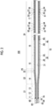
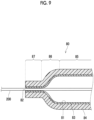
- a catheter 100 includes an elongated catheter body 10 having a resin layer 30 including an inner layer 32 having a lumen 31 and an outer layer 33 formed in an outer periphery of the inner layer 32, and a reinforcement layer 40 incorporated in the resin layer 30 and disposed around the lumen 31 and around the inner layer (32) so as to surround the inner layer (32).
- the catheter 100 includes a ring-shaped marker 70 made of a radiopaque metal material (for example, a platinum alloy).
- the marker 70 is incorporated in the resin layer 30 in a distal end of the catheter body 10, is fixed to a distal end of the reinforcement layer 40, and is disposed around the lumen 31.
- the catheter 100 is an inactive type microcatheter in which an outer diameter of the distal end of the catheter body 10 is 0.6 mm or smaller and a maximum outer diameter of the distal tip 80 is 0.6 mm or smaller.
- the inactive type means a device that changes a curvature of at least a portion of the catheter in a blood vessel and does not depend on electric energy or other power sources (power sources other than power generated by a human body or gravity).
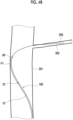
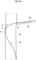
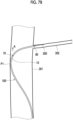
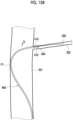
- a medical procedure can be preferably performed so that the catheter 100 enters the perforator 302 through the internal carotid artery 301 having an inner diameter of approximately 5 mm.
- the resin layer 30 forming the catheter body 10 has a layer structure including an inner layer 32 and an outer layer 33 which are respectively made of a resin material.
- the resin layer 30 may be configured to include a hydrophilic coat (to be described below).
- the inner layer 32 has a hollow tube structure.
- the lumen 31 is an internal space of the inner layer 32.
- the lumen 31 is continuously formed from the distal end to the proximal end of the catheter body 10, and the distal end and the proximal end of the catheter body 10 are respectively open.
- the inner layer 83 has a hollow tube structure.
- the distal lumen 81 is an internal space of the inner layer 83.
- the distal lumen 81 is continuously formed from the distal end to the proximal end of the distal tip 80.
- the proximal end of the distal lumen 81 communicates with the distal end of the lumen 31.
- the distal lumen 81 is open in the distal end (distal opening 82).
- the outer layer 84 is linked to the distal side of the outer layer 33.
- the Shore D hardness of the distal tip 80 is 40 or lower.
- the Shore D hardness of the distal tip 80 is 20 or higher.
- the Shore D hardness is determined in accordance with ISO868.
- the Shore D hardness of the distal tip 80 is the Shore D hardness on an outer surface side of the distal tip 80.
- the Shore D hardness is the Shore D hardness of the outer layer 84.
- the reinforcement layer 40 is disposed around the inner layer 32 so as to surround the inner layer 32.
- the reinforcement layer 40 is configured to include a first braid 50 and a second braid 60 disposed in an outer periphery of the first braid 50.
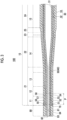
- the first braid 50 is continuously disposed from the distal end to the proximal end of the catheter body 10 (refer to FIGS. 2 and 3 ).
- the second braid 60 is continuously disposed from an intermediate portion to the proximal end of the catheter body 10, but is not disposed in the distal portion of the catheter body 10 (refer to FIG. 2 ).
- Each of these wires is a single wire (not a stranded wire), for example.
- a cross-sectional shape of these wires is not particularly limited. However, for example, a circular shape may be adopted. That is, the wire forming the first braid 50 is a round wire, for example.
- the outer diameters of the first wire 51 to the eighth wire 58 are equal to each other, for example.
- first wire 51, the second wire 52, the third wire 53, and the fourth wire 54 spirally extend parallel to each other. That is, the first wire 51 to the fourth wires 54 are spirally wound around the inner layer 32 at a substantially equal interval in the axial direction of the catheter body 10.
- the remaining fifth wire 55, sixth wire 56, seventh wire 57, and eighth wire 58 spirally extend parallel to each other. That is, the fifth wire 55 to the eighth wire 58 are spirally wound around the inner layer 32 at a substantially equal interval in the axial direction of the catheter body 10.
- a turning direction of a spiral formed by the first wire 51 to the fourth wire 54 and a turning direction of a spiral formed by the fifth wire 55 to the eighth wire 58 are mutually opposite directions (opposite to each other). Therefore, the first wire 51 to the fourth wire 54 and the fifth wire 55 to the eighth wire 58 periodically intersect each other in the axial direction of the catheter body 10.
- each pitch P ( FIG. 3 ) of the wires forming the first braid 50 is larger than the outer diameter of the distal portion (for example, a distal side small diameter region 21 to be described later) of the catheter body 10.
- the pitch P is an inter-axis distance of a pair of adjacent winding portions in each wire.
- a portion of the reinforcement layer 40 which is disposed in the distal portion (for example, the distal side small diameter region 21) of the catheter body 10 is configured to include the braid (first braid 50) in which the wires (for example, the first wire 51 to the eighth wire 58) are braided.
- the pitch of the wires is larger than the outer diameter of the distal portion of the catheter body 10.
- the first braid 50 is configured so that the wires are wound at a constant pitch from the distal end to the proximal end of the first braid 50.
- the second braid 60 is configured by braiding a plurality of wires.
- the second braid 60 is configured so that the eight wires of the first wire 61 to the eighth wire 68 are braided.
- the number of wires forming the second braid 60 is not limited to this example.
- Each of these wires is a single wire (not a stranded wire), for example.
- the cross-sectional shape of these wires is not particularly limited. However, for example, a flat rectangular shape is adopted. That is, the wire forming the second braid 60 is a rectangular wire, for example.
- the cross-sectional shapes and cross-sectional areas of the first wire 61 to the eighth wire 68 are equal to each other, for example.
- the remaining fifth wire 65, sixth wire 66, seventh wire 67, and eighth wire 68 spirally extend parallel to each other. That is, the fifth wire 65 to the eighth wire 68 are spirally wound around the first braid 50 at a substantially equal interval in the axial direction of the catheter body 10.
- a turning direction of a spiral formed by the first wire 61 to the fourth wire 64 and a turning direction of a spiral formed by the fifth wire 65 to the eighth wire 68 are mutually opposite directions (opposite to each other). Therefore, the first wire 61 to the fourth wire 64 and the fifth wire 65 to the eighth wire 68 periodically intersect each other in the axial direction of the catheter body 10.
- the cross-sectional area of the first wire 61 to the eighth wire 68 forming the second braid 60 is larger than the cross-sectional area of the first wire 51 to the eighth wire 58 forming the first braid 50.
- a proximal side portion of the reinforcement layer 40 from the intermediate portion in the longitudinal direction of the catheter body 10 is configured to include the first braid 50 and the second braid 60 braided in the outer periphery of the first braid 50.
- the cross-sectional area of each wire forming the second braid 60 is larger than the cross-sectional area of each wire forming the first braid 50.
- the portion from the intermediate portion to the proximal side portion of the catheter body 10 can have sufficiently ensured rigidity. Accordingly, pushing ability of the catheter 100 can be satisfactorily realized.
Landscapes
- Health & Medical Sciences (AREA)
- Life Sciences & Earth Sciences (AREA)
- Biophysics (AREA)
- Pulmonology (AREA)
- Engineering & Computer Science (AREA)
- Anesthesiology (AREA)
- Biomedical Technology (AREA)
- Heart & Thoracic Surgery (AREA)
- Hematology (AREA)
- Animal Behavior & Ethology (AREA)
- General Health & Medical Sciences (AREA)
- Public Health (AREA)
- Veterinary Medicine (AREA)
- Media Introduction/Drainage Providing Device (AREA)
- External Artificial Organs (AREA)
Claims (10)
- Katheter (100), umfassend:einen Katheterkörper (10) mit einer Harzschicht (30), die eine innere Schicht (32) mit einem Lumen (31) und eine äußere Schicht (33), die in einem äußeren Umfang der inneren Schicht (32) ausgebildet ist, aufweist, und eine Verstärkungsschicht (40), die in die Harzschicht (30) eingearbeitet und um das Lumen (31) und um die innere Schicht (32) herum angeordnet ist, um die innere Schicht (32) zu umgeben;eine ringförmige Markierung (70) aus einem röntgendichten Metallmaterial, wobei die Markierung (70) in die Harzschicht (30) an einem distalen Ende des Katheterkörpers (10) eingearbeitet ist, an einem distalen Ende der Verstärkungsschicht (40) befestigt ist und um das Lumen (31) herum angeordnet ist; undeine distale Spitze (80) aus einem Harz, die mit dem distalen Ende des Katheterkörpers (10) verbunden ist, wobei die distale Spitze (80) ein distales Lumen (81) aufweist, das mit dem Lumen (31) in Verbindung steht und ein offenes distales Ende (82) hat,wobei ein Außendurchmesser des distalen Endes des Katheterkörpers (10) 0,6 mm oder kleiner ist, und ein maximaler Außendurchmesser der distalen Spitze (80) 0,6 mm oder kleiner ist, unddadurch gekennzeichnet, dassdie Verstärkungsschicht (40) so konfiguriert ist, dass sie ein erstes Geflecht (50) und ein zweites Geflecht (60), das in einem äußeren Umfang des ersten Geflechts (50) angeordnet ist, umfasst,wobei das erste Geflecht (50) kontinuierlich von dem distalen Ende zu einem proximalen Ende des Katheterkörpers (10) angeordnet ist und wobei das zweite Geflecht (60) kontinuierlich von einem Zwischenabschnitt zu dem proximalen Ende des Katheterkörpers (10) angeordnet ist, aber nicht in einem distalen Abschnitt des Katheterkörpers (10) angeordnet ist,die distale Spitze (80) eine Shore D-Härte, gemessen nach ISO686, von 20 bis 40 aufweist,eine Abmessung der Markierung (70) in einer axialen Richtung des Katheterkörpers (10) kleiner ist als ein maximaler Außendurchmesser der distalen Spitze (80), und eine Länge der distalen Spitze (80) in der axialen Richtung der distalen Spitze (80) das 3- bis 18-fache des maximalen Außendurchmessers der distalen Spitze (80) beträgt.
- Katheter (100) nach Anspruch 1,
wobei in einem Abschnitt der Verstärkungsschicht (40), der in einem distalen Abschnitt des Katheterkörpers (10) angeordnet ist, das erste Geflecht (50) durch Flechten von Drähten mit einem Abstand, der größer als ein Außendurchmesser des distalen Abschnitts des Katheterkörpers (10) ist, konfiguriert ist. - Katheter (100) nach Anspruch 1 oder 2,
wobei ein Außendurchmesser der distalen Spitze (80) unabhängig von einer Position der distalen Spitze (80) in einer axialen Richtung konstant ist. - Katheter (100) nach Anspruch 1 oder 2,
wobei die distale Spitze (80) aufweist:einen ersten Bereich (85) mit konstantem Durchmesser, dessen Außendurchmesser und Innendurchmesser unabhängig von einer Position der distalen Spitze (80) in der axialen Richtung konstant sind,einen Bereich (86) mit reduziertem Durchmesser, der mit einer distalen Seite des ersten Bereichs (85) mit konstantem Durchmesser verbunden ist und dessen Außendurchmesser und Innendurchmesser in Richtung der distalen Seite reduziert sind, undeinen zweiten Bereich (87) mit konstantem Durchmesser, der mit einer distalen Seite des Bereichs (86) mit reduziertem Durchmesser verbunden ist und dessen Außendurchmesser und Innendurchmesser unabhängig von einer Position der distalen Spitze (80) in der axialen Richtung konstant sind. - Katheter (100) nach einem der Ansprüche 1 bis 4,
wobei der Katheterkörper (10) aufweist:einen ersten distalen Bereich (11), der mit einer proximalen Seite der distalen Spitze (80) verbunden ist, undeinen zweiten distalen Bereich (12), der mit einer proximalen Seite des ersten distalen Bereichs (11) verbunden ist,wobei der erste distale Bereich (11) aus einem Harzmaterial hergestellt ist, das das gleiche wie das der distalen Spitze (80) ist,wobei der zweite distale Bereich (12) aus einem Harzmaterial hergestellt ist, das härter ist als das Harzmaterial, das den ersten distalen Bereich (11) bildet, undwobei die Verstärkungsschicht (40) durchgehend über den gesamten ersten distalen Bereich (11) und den zweiten distalen Bereich (12) angeordnet ist. - Katheter (100) nach Anspruch 5,
wobei der Katheterkörper (10) einen Bereich (22) mit vergrößertem Durchmesser aufweist, in dem ein Innendurchmesser des Lumens (31) und ein Außendurchmesser des Katheterkörpers (10) in Richtung der proximalen Seite allmählich vergrößert sind, wobei der Bereich (22) mit vergrößertem Durchmesser auf der proximalen Seite des zweiten distalen Bereichs (12) angeordnet ist. - Katheter (100) nach Anspruch 6,
wobei in einem Bereich (14) von der distalen Seite des Bereichs (22) mit vergrößertem Durchmesser bis zur proximalen Seite des Bereichs (22) mit vergrößertem Durchmesser in dem Katheterkörper (10) die Harzschicht (30) aus dem gleichen Harzmaterial hergestellt ist. - Katheter (100) nach Anspruch 6 oder 7,wobei ein an die proximale Seite des Bereichs (22) mit vergrößertem Durchmesser in dem Katheterkörper (10) angrenzender Bereich ein Bereich (23) mit kleinem Durchmesser ist, der den gleichen Außendurchmesser wie das proximale Ende des Bereichs (22) mit vergrößertem Durchmesser hat, undwobei ein an eine proximale Seite des Bereichs (23) mit kleinem Durchmesser in dem Katheterkörper (10) angrenzender Bereich ein Bereich (24) mit großem Durchmesser ist, der einen größeren Durchmesser als der Bereich (23) mit kleinem Durchmesser hat.
- Katheter (100) nach einem der Ansprüche 1 bis 8,
wobei eine Querschnittsfläche jedes Drahtes, der das zweite Geflecht (60) bildet, größer ist als eine Querschnittsfläche jedes Drahtes, der das erste Geflecht (50) bildet. - Katheter-Kit, umfassend:den Katheter (100) nach Anspruch 4; undeinen Führungsdraht (200), der durch Einführen in das Lumen (31) verwendet wird, wobei der Innendurchmesser des zweiten Bereichs (87) mit konstantem Durchmesser der gleiche ist wie ein Außendurchmesser eines distalen Abschnitts des Führungsdrahts (200).
Applications Claiming Priority (2)
| Application Number | Priority Date | Filing Date | Title |
|---|---|---|---|
| JP2017162592A JP7006020B2 (ja) | 2017-08-25 | 2017-08-25 | カテーテル、及び、カテーテルキット |
| PCT/JP2018/031348 WO2019039589A1 (ja) | 2017-08-25 | 2018-08-24 | カテーテル、及び、カテーテルキット |
Publications (4)
| Publication Number | Publication Date |
|---|---|
| EP3673947A1 EP3673947A1 (de) | 2020-07-01 |
| EP3673947A4 EP3673947A4 (de) | 2021-06-09 |
| EP3673947C0 EP3673947C0 (de) | 2025-07-02 |
| EP3673947B1 true EP3673947B1 (de) | 2025-07-02 |
Family
ID=65438893
Family Applications (1)
| Application Number | Title | Priority Date | Filing Date |
|---|---|---|---|
| EP18849291.2A Active EP3673947B1 (de) | 2017-08-25 | 2018-08-24 | Katheter und katheterkit |
Country Status (7)
| Country | Link |
|---|---|
| US (1) | US11389620B2 (de) |
| EP (1) | EP3673947B1 (de) |
| JP (1) | JP7006020B2 (de) |
| CN (1) | CN111032142A (de) |
| ES (1) | ES3037155T3 (de) |
| TW (1) | TWI774832B (de) |
| WO (1) | WO2019039589A1 (de) |
Families Citing this family (30)
| Publication number | Priority date | Publication date | Assignee | Title |
|---|---|---|---|---|
| CN108135591B (zh) | 2016-02-24 | 2021-05-28 | 禾木(中国)生物工程有限公司 | 柔性增强的神经血管导管 |
| JP7264581B2 (ja) | 2017-01-06 | 2023-04-25 | インセプト、リミテッド、ライアビリティ、カンパニー | 動脈瘤治療装置向けの抗血栓性コーティング |
| CN111601632B (zh) * | 2018-01-26 | 2022-06-07 | 朝日英达科株式会社 | 导管 |
| WO2019189533A1 (ja) * | 2018-03-29 | 2019-10-03 | テルモ株式会社 | カテーテル組立体 |
| CN119405388A (zh) | 2018-05-01 | 2025-02-11 | 因赛普特有限责任公司 | 用于从血管内部位去除闭塞性物质的装置和方法 |
| US11395665B2 (en) | 2018-05-01 | 2022-07-26 | Incept, Llc | Devices and methods for removing obstructive material, from an intravascular site |
| US11517335B2 (en) | 2018-07-06 | 2022-12-06 | Incept, Llc | Sealed neurovascular extendable catheter |
| US11471582B2 (en) | 2018-07-06 | 2022-10-18 | Incept, Llc | Vacuum transfer tool for extendable catheter |
| US11766539B2 (en) | 2019-03-29 | 2023-09-26 | Incept, Llc | Enhanced flexibility neurovascular catheter |
| WO2021064955A1 (ja) * | 2019-10-03 | 2021-04-08 | 朝日インテック株式会社 | 医療用管状体 |
| EP4044906B1 (de) | 2019-10-15 | 2025-03-12 | Kandu Health, Inc. | Systeme und verfahren zur mehrgrössenhubdetektion |
| CN114555168A (zh) * | 2019-11-08 | 2022-05-27 | 朝日英达科株式会社 | 导管 |
| JP2023507553A (ja) | 2019-12-18 | 2023-02-24 | インパラティブ、ケア、インク. | 静脈血栓塞栓症を治療するための方法及びシステム |
| US11633272B2 (en) | 2019-12-18 | 2023-04-25 | Imperative Care, Inc. | Manually rotatable thrombus engagement tool |
| US11457936B2 (en) | 2019-12-18 | 2022-10-04 | Imperative Care, Inc. | Catheter system for treating thromboembolic disease |
| US20230248498A1 (en) | 2019-12-18 | 2023-08-10 | Imperative Care, Inc. | Manually rotatable thrombus engagement tool |
| WO2021183444A1 (en) | 2020-03-10 | 2021-09-16 | Imperative Care, Inc. | Enhanced flexibility neurovascular catheter |
| CN121490235A (zh) * | 2020-05-27 | 2026-02-10 | 深圳北芯生命科技股份有限公司 | 具有编织层的微导管 |
| CN115666698B (zh) * | 2020-06-12 | 2025-08-01 | 泰尔茂株式会社 | 导管 |
| CN111803782A (zh) * | 2020-08-18 | 2020-10-23 | 上海上医康鸽医用器材有限责任公司 | 可塑型子宫输卵管造影导管装置 |
| WO2022071041A1 (ja) | 2020-09-30 | 2022-04-07 | テルモ株式会社 | 経皮カテーテル |
| US12558175B2 (en) | 2021-08-12 | 2026-02-24 | Imperative Care, Inc. | Multi catheter method of performing a robotic neurovascular procedure |
| KR20240049675A (ko) * | 2021-08-27 | 2024-04-16 | 에드워즈 라이프사이언시스 코포레이션 | 인공 장치를 이식하기 위한 전달 장치 및 방법 |
| US20230082226A1 (en) * | 2021-09-03 | 2023-03-16 | Scientia Vascular, Inc. | Intravascular guidewire and microcatheter system |
| US20230071512A1 (en) * | 2021-09-03 | 2023-03-09 | Scientia Vascular, Inc. | Microcatheter device with non-linear bending stiffness |
| CA3234508A1 (en) * | 2021-10-08 | 2023-04-13 | Surmodics Md, Llc | Catheter with multiple braid layers |
| USD1077996S1 (en) | 2021-10-18 | 2025-06-03 | Imperative Care, Inc. | Inline fluid filter |
| JP2025505027A (ja) * | 2022-02-06 | 2025-02-19 | トロ ニューロバスキュラー インコーポレーテッド | 先端形状を有する神経血管吸引カテーテル |
| CN115970127A (zh) * | 2022-12-30 | 2023-04-18 | 江苏赛腾医疗科技有限公司 | 医用插管 |
| US12171917B1 (en) | 2024-01-08 | 2024-12-24 | Imperative Care, Inc. | Devices for blood capture and reintroduction during aspiration procedure |
Family Cites Families (15)
| Publication number | Priority date | Publication date | Assignee | Title |
|---|---|---|---|---|
| JP3587567B2 (ja) * | 1994-09-08 | 2004-11-10 | テルモ株式会社 | カテーテルチューブ |
| US6355027B1 (en) * | 1999-06-09 | 2002-03-12 | Possis Medical, Inc. | Flexible microcatheter |
| US6210396B1 (en) | 1999-06-24 | 2001-04-03 | Medtronic, Inc. | Guiding catheter with tungsten loaded band |
| JP2001190681A (ja) * | 2000-01-12 | 2001-07-17 | Terumo Corp | カテーテル |
| JP4544526B2 (ja) * | 2005-06-23 | 2010-09-15 | 株式会社プラ技研 | カテーテル |
| JP2007082802A (ja) | 2005-09-22 | 2007-04-05 | Kaneka Corp | 医療用カテーテルチューブ |
| JP2007236472A (ja) | 2006-03-06 | 2007-09-20 | Terumo Corp | カテーテル |
| JP4743800B2 (ja) * | 2008-10-11 | 2011-08-10 | 朝日インテック株式会社 | カテーテル |
| JP5769992B2 (ja) * | 2011-03-23 | 2015-08-26 | 株式会社グッドマン | カテーテル |
| US9445897B2 (en) | 2012-05-01 | 2016-09-20 | Direct Flow Medical, Inc. | Prosthetic implant delivery device with introducer catheter |
| JP2014100339A (ja) * | 2012-11-20 | 2014-06-05 | Terumo Corp | カテーテル用チューブの製造方法およびカテーテル用チューブの連続体 |
| RU2693209C2 (ru) | 2013-05-19 | 2019-07-01 | Кардинал Хелт Свитзерлэнд 515 ГмбХ | Направляющий катетер с большим просветом |
| JP5901078B2 (ja) * | 2014-03-25 | 2016-04-06 | 朝日インテック株式会社 | カテーテル |
| JP6381138B2 (ja) * | 2015-02-13 | 2018-08-29 | 朝日インテック株式会社 | カテーテル |
| JP2017162592A (ja) | 2016-03-08 | 2017-09-14 | 株式会社豊田自動織機 | 非水系二次電池並びにこれに用いられるガス発生抑制剤及び非水系電解液 |
-
2017
- 2017-08-25 JP JP2017162592A patent/JP7006020B2/ja active Active
-
2018
- 2018-08-24 TW TW107129616A patent/TWI774832B/zh active
- 2018-08-24 US US16/641,099 patent/US11389620B2/en active Active
- 2018-08-24 CN CN201880054834.7A patent/CN111032142A/zh active Pending
- 2018-08-24 EP EP18849291.2A patent/EP3673947B1/de active Active
- 2018-08-24 ES ES18849291T patent/ES3037155T3/es active Active
- 2018-08-24 WO PCT/JP2018/031348 patent/WO2019039589A1/ja not_active Ceased
Also Published As
| Publication number | Publication date |
|---|---|
| EP3673947C0 (de) | 2025-07-02 |
| TWI774832B (zh) | 2022-08-21 |
| JP2019037572A (ja) | 2019-03-14 |
| EP3673947A4 (de) | 2021-06-09 |
| CN111032142A (zh) | 2020-04-17 |
| EP3673947A1 (de) | 2020-07-01 |
| ES3037155T3 (en) | 2025-09-29 |
| WO2019039589A1 (ja) | 2019-02-28 |
| TW201922310A (zh) | 2019-06-16 |
| US11389620B2 (en) | 2022-07-19 |
| JP7006020B2 (ja) | 2022-01-24 |
| US20200188630A1 (en) | 2020-06-18 |
Similar Documents
| Publication | Publication Date | Title |
|---|---|---|
| US11389620B2 (en) | Catheter and catheter kit | |
| EP3546008B1 (de) | Katheter und verfahren zur herstellung davon | |
| US20220355087A1 (en) | Hybrid Transseptal Dilator and Methods of Using the Same | |
| AU2011242906B2 (en) | Low profile guiding catheter for neurovascular applications | |
| US20060264905A1 (en) | Improved Catheters | |
| EP2338556A2 (de) | Führungsdraht | |
| US20150051541A1 (en) | Medical instrument and method of manufacturing medical instrument | |
| EP2749314A1 (de) | Führungsdraht | |
| CN106456942B (zh) | 具有改善刚度的抗扭结导丝 | |
| EP3130372B1 (de) | Katheter und ballonkatheter | |
| EP2502645A1 (de) | Führungsdraht | |
| CN110193130B (zh) | 导丝 | |
| JP2010042115A (ja) | 柔軟性が変化する医療用チューブ | |
| JP2024500098A (ja) | 医療用カテーテルおよびその製造方法 | |
| US11026669B2 (en) | Collapsible dilator | |
| US20140188005A1 (en) | Wire guide and method of making the same | |
| US20190015629A1 (en) | Multi-Lumen Catheters for Small Body Vessel Applications | |
| US20250262412A1 (en) | Medical devices including laser cut tube | |
| JP3179894U (ja) | カテーテル | |
| EP3995170B1 (de) | Kathetergeflechtdraht mit variabler querschnittsform | |
| US20250262411A1 (en) | Intravascular medical devices including laser cut tube | |
| JP4316252B2 (ja) | カテーテル | |
| JP2017158958A (ja) | ガイドワイヤ | |
| JP2007319533A (ja) | 医療用マイクロカテーテル |
Legal Events
| Date | Code | Title | Description |
|---|---|---|---|
| STAA | Information on the status of an ep patent application or granted ep patent |
Free format text: STATUS: THE INTERNATIONAL PUBLICATION HAS BEEN MADE |
|
| PUAI | Public reference made under article 153(3) epc to a published international application that has entered the european phase |
Free format text: ORIGINAL CODE: 0009012 |
|
| STAA | Information on the status of an ep patent application or granted ep patent |
Free format text: STATUS: REQUEST FOR EXAMINATION WAS MADE |
|
| 17P | Request for examination filed |
Effective date: 20200221 |
|
| AK | Designated contracting states |
Kind code of ref document: A1 Designated state(s): AL AT BE BG CH CY CZ DE DK EE ES FI FR GB GR HR HU IE IS IT LI LT LU LV MC MK MT NL NO PL PT RO RS SE SI SK SM TR |
|
| AX | Request for extension of the european patent |
Extension state: BA ME |
|
| DAV | Request for validation of the european patent (deleted) | ||
| DAX | Request for extension of the european patent (deleted) | ||
| REG | Reference to a national code |
Ref country code: DE Ref legal event code: R079 Free format text: PREVIOUS MAIN CLASS: A61M0025098000 Ipc: A61M0025000000 Ref document number: 602018083279 Country of ref document: DE |
|
| A4 | Supplementary search report drawn up and despatched |
Effective date: 20210510 |
|
| RIC1 | Information provided on ipc code assigned before grant |
Ipc: A61M 25/00 20060101AFI20210503BHEP Ipc: A61M 25/01 20060101ALI20210503BHEP Ipc: A61M 25/098 20060101ALI20210503BHEP |
|
| STAA | Information on the status of an ep patent application or granted ep patent |
Free format text: STATUS: EXAMINATION IS IN PROGRESS |
|
| 17Q | First examination report despatched |
Effective date: 20240419 |
|
| GRAP | Despatch of communication of intention to grant a patent |
Free format text: ORIGINAL CODE: EPIDOSNIGR1 |
|
| STAA | Information on the status of an ep patent application or granted ep patent |
Free format text: STATUS: GRANT OF PATENT IS INTENDED |
|
| INTG | Intention to grant announced |
Effective date: 20250204 |
|
| RIN1 | Information on inventor provided before grant (corrected) |
Inventor name: SUGIHARA, YUSAKU Inventor name: SHIMIZU, TAICHI Inventor name: MATSUMOTO, YASUSHI Inventor name: FUJITA, YASUHIRO |
|
| GRAS | Grant fee paid |
Free format text: ORIGINAL CODE: EPIDOSNIGR3 |
|
| GRAA | (expected) grant |
Free format text: ORIGINAL CODE: 0009210 |
|
| STAA | Information on the status of an ep patent application or granted ep patent |
Free format text: STATUS: THE PATENT HAS BEEN GRANTED |
|
| AK | Designated contracting states |
Kind code of ref document: B1 Designated state(s): AL AT BE BG CH CY CZ DE DK EE ES FI FR GB GR HR HU IE IS IT LI LT LU LV MC MK MT NL NO PL PT RO RS SE SI SK SM TR |
|
| REG | Reference to a national code |
Ref country code: GB Ref legal event code: FG4D |
|
| REG | Reference to a national code |
Ref country code: CH Ref legal event code: EP |
|
| REG | Reference to a national code |
Ref country code: DE Ref legal event code: R096 Ref document number: 602018083279 Country of ref document: DE |
|
| REG | Reference to a national code |
Ref country code: IE Ref legal event code: FG4D |
|
| U01 | Request for unitary effect filed |
Effective date: 20250718 |
|
| U07 | Unitary effect registered |
Designated state(s): AT BE BG DE DK EE FI FR IT LT LU LV MT NL PT RO SE SI Effective date: 20250725 |
|
| U20 | Renewal fee for the european patent with unitary effect paid |
Year of fee payment: 8 Effective date: 20250820 |
|
| REG | Reference to a national code |
Ref country code: ES Ref legal event code: FG2A Ref document number: 3037155 Country of ref document: ES Kind code of ref document: T3 Effective date: 20250929 |
|
| PGFP | Annual fee paid to national office [announced via postgrant information from national office to epo] |
Ref country code: ES Payment date: 20250925 Year of fee payment: 8 |
|
| PGFP | Annual fee paid to national office [announced via postgrant information from national office to epo] |
Ref country code: GB Payment date: 20250828 Year of fee payment: 8 |
|
| PG25 | Lapsed in a contracting state [announced via postgrant information from national office to epo] |
Ref country code: IS Free format text: LAPSE BECAUSE OF FAILURE TO SUBMIT A TRANSLATION OF THE DESCRIPTION OR TO PAY THE FEE WITHIN THE PRESCRIBED TIME-LIMIT Effective date: 20251102 |
|
| PG25 | Lapsed in a contracting state [announced via postgrant information from national office to epo] |
Ref country code: NO Free format text: LAPSE BECAUSE OF FAILURE TO SUBMIT A TRANSLATION OF THE DESCRIPTION OR TO PAY THE FEE WITHIN THE PRESCRIBED TIME-LIMIT Effective date: 20251002 |
|
| PG25 | Lapsed in a contracting state [announced via postgrant information from national office to epo] |
Ref country code: HR Free format text: LAPSE BECAUSE OF FAILURE TO SUBMIT A TRANSLATION OF THE DESCRIPTION OR TO PAY THE FEE WITHIN THE PRESCRIBED TIME-LIMIT Effective date: 20250702 |
|
| PG25 | Lapsed in a contracting state [announced via postgrant information from national office to epo] |
Ref country code: GR Free format text: LAPSE BECAUSE OF FAILURE TO SUBMIT A TRANSLATION OF THE DESCRIPTION OR TO PAY THE FEE WITHIN THE PRESCRIBED TIME-LIMIT Effective date: 20251003 |
|
| PG25 | Lapsed in a contracting state [announced via postgrant information from national office to epo] |
Ref country code: CZ Free format text: LAPSE BECAUSE OF FAILURE TO SUBMIT A TRANSLATION OF THE DESCRIPTION OR TO PAY THE FEE WITHIN THE PRESCRIBED TIME-LIMIT Effective date: 20250702 |
|
| PG25 | Lapsed in a contracting state [announced via postgrant information from national office to epo] |
Ref country code: PL Free format text: LAPSE BECAUSE OF FAILURE TO SUBMIT A TRANSLATION OF THE DESCRIPTION OR TO PAY THE FEE WITHIN THE PRESCRIBED TIME-LIMIT Effective date: 20250702 |
|
| PG25 | Lapsed in a contracting state [announced via postgrant information from national office to epo] |
Ref country code: RS Free format text: LAPSE BECAUSE OF FAILURE TO SUBMIT A TRANSLATION OF THE DESCRIPTION OR TO PAY THE FEE WITHIN THE PRESCRIBED TIME-LIMIT Effective date: 20251002 |
|
| REG | Reference to a national code |
Ref country code: CH Ref legal event code: H13 Free format text: ST27 STATUS EVENT CODE: U-0-0-H10-H13 (AS PROVIDED BY THE NATIONAL OFFICE) Effective date: 20260324 |
|
| PG25 | Lapsed in a contracting state [announced via postgrant information from national office to epo] |
Ref country code: SM Free format text: LAPSE BECAUSE OF FAILURE TO SUBMIT A TRANSLATION OF THE DESCRIPTION OR TO PAY THE FEE WITHIN THE PRESCRIBED TIME-LIMIT Effective date: 20250702 |
|
| PG25 | Lapsed in a contracting state [announced via postgrant information from national office to epo] |
Ref country code: CH Free format text: LAPSE BECAUSE OF NON-PAYMENT OF DUE FEES Effective date: 20250831 |
|
| PG25 | Lapsed in a contracting state [announced via postgrant information from national office to epo] |
Ref country code: SK Free format text: LAPSE BECAUSE OF FAILURE TO SUBMIT A TRANSLATION OF THE DESCRIPTION OR TO PAY THE FEE WITHIN THE PRESCRIBED TIME-LIMIT Effective date: 20250702 |
|
| PLBE | No opposition filed within time limit |
Free format text: ORIGINAL CODE: 0009261 |
|
| STAA | Information on the status of an ep patent application or granted ep patent |
Free format text: STATUS: NO OPPOSITION FILED WITHIN TIME LIMIT |
|
| REG | Reference to a national code |
Ref country code: CH Ref legal event code: L10 Free format text: ST27 STATUS EVENT CODE: U-0-0-L10-L00 (AS PROVIDED BY THE NATIONAL OFFICE) Effective date: 20260518 |
|
| 26N | No opposition filed |
Effective date: 20260407 |
|
| PG25 | Lapsed in a contracting state [announced via postgrant information from national office to epo] |
Ref country code: MC Free format text: LAPSE BECAUSE OF FAILURE TO SUBMIT A TRANSLATION OF THE DESCRIPTION OR TO PAY THE FEE WITHIN THE PRESCRIBED TIME-LIMIT Effective date: 20250702 |
|
| PG25 | Lapsed in a contracting state [announced via postgrant information from national office to epo] |
Ref country code: IE Free format text: LAPSE BECAUSE OF NON-PAYMENT OF DUE FEES Effective date: 20250824 |