EP3674023A1 - Einsatz - Google Patents
Einsatz Download PDFInfo
- Publication number
- EP3674023A1 EP3674023A1 EP18848561.9A EP18848561A EP3674023A1 EP 3674023 A1 EP3674023 A1 EP 3674023A1 EP 18848561 A EP18848561 A EP 18848561A EP 3674023 A1 EP3674023 A1 EP 3674023A1
- Authority
- EP
- European Patent Office
- Prior art keywords
- ridge line
- cutting edge
- region
- corner
- insert
- Prior art date
- Legal status (The legal status is an assumption and is not a legal conclusion. Google has not performed a legal analysis and makes no representation as to the accuracy of the status listed.)
- Pending
Links
Images








Classifications
-
- B—PERFORMING OPERATIONS; TRANSPORTING
- B23—MACHINE TOOLS; METAL-WORKING NOT OTHERWISE PROVIDED FOR
- B23C—MILLING
- B23C5/00—Milling-cutters
- B23C5/16—Milling-cutters characterised by physical features other than shape
- B23C5/20—Milling-cutters characterised by physical features other than shape with removable cutter bits or teeth or cutting inserts
- B23C5/202—Plate-like cutting inserts with special form
- B23C5/205—Plate-like cutting inserts with special form characterised by chip-breakers of special form
-
- B—PERFORMING OPERATIONS; TRANSPORTING
- B23—MACHINE TOOLS; METAL-WORKING NOT OTHERWISE PROVIDED FOR
- B23C—MILLING
- B23C5/00—Milling-cutters
- B23C5/16—Milling-cutters characterised by physical features other than shape
- B23C5/20—Milling-cutters characterised by physical features other than shape with removable cutter bits or teeth or cutting inserts
- B23C5/202—Plate-like cutting inserts with special form
-
- B—PERFORMING OPERATIONS; TRANSPORTING
- B23—MACHINE TOOLS; METAL-WORKING NOT OTHERWISE PROVIDED FOR
- B23C—MILLING
- B23C2200/00—Details of milling cutting inserts
- B23C2200/08—Rake or top surfaces
-
- B—PERFORMING OPERATIONS; TRANSPORTING
- B23—MACHINE TOOLS; METAL-WORKING NOT OTHERWISE PROVIDED FOR
- B23C—MILLING
- B23C2200/00—Details of milling cutting inserts
- B23C2200/08—Rake or top surfaces
- B23C2200/081—Rake or top surfaces with projections
-
- B—PERFORMING OPERATIONS; TRANSPORTING
- B23—MACHINE TOOLS; METAL-WORKING NOT OTHERWISE PROVIDED FOR
- B23C—MILLING
- B23C2200/00—Details of milling cutting inserts
- B23C2200/32—Chip breaking or chip evacuation
- B23C2200/326—Chip breaking or chip evacuation by chip-breaking grooves
-
- B—PERFORMING OPERATIONS; TRANSPORTING
- B23—MACHINE TOOLS; METAL-WORKING NOT OTHERWISE PROVIDED FOR
- B23C—MILLING
- B23C5/00—Milling-cutters
- B23C5/02—Milling-cutters characterised by the shape of the cutter
- B23C5/10—Shank-type cutters, i.e. with an integral shaft
- B23C5/109—Shank-type cutters, i.e. with an integral shaft with removable cutting inserts
Definitions
- the present embodiments generally relate to inserts for use in a cutting process. More specifically, the present embodiments relate to inserts used for rotary tools.
- a cutting tool described in Japanese Unexamined Patent Publication No. 2008-279519 is one which is usable for a cutting process of a workpiece.
- a cutting insert (an insert) in the cutting tool described in Patent Document 1 has a polygonal plate shape and includes a cutting edge located on a ridge line where a polygonal surface intersects with an outer peripheral surface.
- the cutting tool described in Patent Document 1 is usable for a three-dimensional process, such as ramping process.
- An insert in one of embodiments includes a first surface, a second surface, and a ridge line where the first surface intersects with the second surface.
- the first surface includes a first corner, a first side extended from the first corner, and a second side extended from the first corner.
- the ridge line includes a corner cutting edge located on the first corner, a first cutting edge located on at least a part of the first side, and a second cutting edge located on at least a part of the second side.
- the first surface further includes a first region located from the first cutting edge toward a midportion of the first surface, a second region located from the second cutting edge toward the midportion of the first surface, and a concave part located on at least one of the first region and the second region.
- An insert in one of embodiments includes a first surface, a second surface, and a ridge line where the first surface intersects with the second surface.
- the first surface includes a first corner, a first side extended from the first corner, and a second side extended from the first corner.
- the ridge line includes a corner cutting edge located on the first corner, a first cutting edge located on at least a part of the first side, and a second cutting edge located on at least a part of the second side.
- the first surface further includes a first region located from the first cutting edge toward a midportion of the first surface, a second region located from the second cutting edge toward the midportion of the first surface, and a convex part located on at least one of the first region and the second region.
- the insert 1 in one of the embodiments includes a first surface 3 (an upper surface in FIG. 1 ), a second surface 5 (a side surface in FIG. 1 ), and a ridge line 7 where the first surface 3 intersects with the second surface 5.
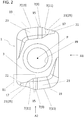
- the first surface 3 has a polygonal shape, and the first surface 3 has an approximately hexagonal shape in one embodiment illustrated in FIG. 2 . Accordingly, the first surface 3 includes six corners and six sides. Because the first surface 3 has the approximately hexagonal shape, the second surface 5 includes six planar regions.
- the first surface 3 includes a first corner 9, and a first side 11 and a second side 13 each extended from the first corner 9.
- the first corner 9 is one of the six corners included in the first surface 3 in FIG. 2 .
- the first side 11 and the second side 13 are two of the six sides included in the first surface 3.
- the first corner 9 may be rephrased as a protruded part protruded in a direction away from a midportion of the first surface 3 in a front view of the first surface 3.
- the first surface 3 may have an approximately polygonal shape and need not be a strict polygonal shape.
- the sides in the first surface 3 having the polygonal shape need not have a strict straight line shape or, alternatively, these sides may have, for example, a convex curvilinear shape or concave curvilinear shape.
- the corners in the first surface 3 having the polygonal shape are not limited to a structure formed by intersection of two straight lines, but may have, for example, an outwardly rounded shape.
- the shape of the first surface 3 is not limited to the above configuration. There is no problem even if the first surface 3 has a quadrangular shape, pentagonal shape or octagonal shape instead of the hexagonal shape. Dimensions of the insert 1 are not particularly limited. For example, a maximum width of the first surface 3 may be set to, approximately 3-20 mm. A height from the first surface 3 to the third surface 6 may be set to approximately 5-20 mm.
- the insert 1 may include a hole 39 that opens into the first surface 3.
- the hole 39 may penetrate through the third surface 6 located on opposite side of the first surface 3.
- the hole 39 is not limited to the above embodiment but may open into the second surface 5.
- the hole 39 may be configured to penetrate through the two planar regions located opposite sides on the second surface.
- the hole 39 may be used as an insertion hole for a fixing tool when attaching the insert 1 to a holder.
- the fixing tool include a screw and a wedge.
- the insert 1 may be fixed to the holder by using a brazing material.
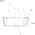
- the insert 1 includes a cutting edge located at least on a part of the ridge line 7 in the present embodiment.
- the ridge line 7 includes a corner cutting edge 15 located on the first corner 9, a first cutting edge 17 located on at least a part of the first side 11, and a second cutting edge 19 located on at least the second side 13.
- the first cutting edge 17 may connect to the corner cutting edge 15.
- the second cutting edge 19 may connect to the corner cutting edge 15.
- the first cutting edge 17 may be located on only the part or the whole of the first side 11.
- the second cutting edge 19 may be located on only the part or the whole of the second side 13.
- a so-called honing process may be applied to the corner cutting edge 15, the first cutting edge 17 and the second cutting edge 19.
- the ridge line 7 where the first surface 3 intersects with the second surface 5 may not be a strict line shape obtained by intersection of the two surfaces.
- the first surface 3 also includes a first region 21 located from the first cutting edge 17 toward a midportion of the first surface 3, and a second region 23 located from the second cutting edge 19 toward the midportion of the first surface 3.
- the first region 21 and the second region 23 may serve as a rake surface.
- the first surface 3 includes a concave part 25 located in at least one of the first region 21 and the second region 23.
- the first surface 3 includes the concave part 25 extended from a side of the ridge line 7 toward the midportion of the first surface 3 in FIGs. 1 to 6.
- FIGs. 1 to 6 illustrate one embodiment in which the concave part 25 is located in the first region 21.
- toward the midportion of the first surface 3 denotes “toward the midportion of the first surface 3 in a front view from the ridge line 7 of the first surface 3,” but need not be strictly directed toward the midportion of the first surface 3 in the present embodiment.
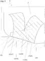
- FIG. 7 illustrates an example of how the chips are divided apart by the contact with the concave part 25.
- the chips are divided apart along a chip extending direction in the example illustrated in FIG. 7 .
- the chips so divided apart have a small width.
- the chips having the small width tend to be curled while being grazed on the first surface 3.
- the curled chips tend to be well divided apart.
- the chips are less likely to extend long because the chips are divided apart. This makes it easier for the chips to be discharged well. Chip clogging is less likely to occur because of good chip discharge performance. Additionally, a machined surface is less susceptible to damage due to the chips.
- chips may be divided apart in a direction orthogonal to the chip extending direction. This is because the chips become less likely to be curled due to bending by the contact with the concave part 25.
- the chips less likely to be curled are further bent in the direction orthogonal to the chip extending direction.
- the chips tend to be divided apart from a bent portion in the direction orthogonal to the chip extending direction. In other words, the chips are less likely to be curled and are divided apart at short intervals in the chip extending direction. The chips thus divided in short lengths tend to be discharged well.
- the concave part 25 is extended from the side of the ridge line 7 toward the midportion of the first surface 3, the concave part 25 serves as a chip flow guide, thus leading to a better chip discharge.
- a length N1 of the concave part 25 in a direction orthogonal to the first cutting edge 17 in cases where the concave part 25 is located in the first region 21 may be expressed by 0.03 M1 to 0.24 M1 where M1 is a length of the first cutting edge 17.
- a length N2 of the concave part 25 in a direction orthogonal to the second cutting edge 19 in cases where the concave part 25 is located in the second region 23 may be expressed by 0.03 M2 to 0.24 M2 where M2 is a length of the second cutting edge 19.
- the concave part 25 may be located in one of the first region 21 and the second region 23. Alternatively, the concave part 25 may be located in both the first region 21 and the second region 23. The concave part 25 is located in the first region 21 in the embodiment illustrated in FIG. 2 as described above.
- the first cutting edge 17 on the ridge line 7 is capable of serving as an inner peripheral cutting edge
- the second cutting edge 19 on the ridge line 7 is capable of serving as an outer peripheral cutting edge.
- the second cutting edge 19 is usable mainly during a face milling process.
- the first cutting edge 17 is also usable during a ramping process.
- Chips generated by the first cutting edge 17 serving as the inner peripheral cutting edge are relatively thin, and therefore, a flow of the chips generated by the first cutting edge 17 becomes unstable and are liable to extend long. However, the chips generated by the first cutting edge 17 can be stably divided apart if the concave part 25 is located in the first region 21.
- a good machined surface is obtainable if the concave part 25 is located in the second region 23.
- Chips generated by the second cutting edge 19 serving as the outer peripheral cutting edge are relatively thick, and the machined surface is therefore susceptible to damage upon occurrence of chip clogging.
- the chips generated by the second cutting edge 19 can be stably divided apart if the concave part 25 is located in the second region 23. Consequently, the chip clogging is less likely to occur, thus leading to the good machined surface.
- the concave part 25 may be located away from the ridge line 7, or alternatively, may include a part of the ridge line 7 as illustrated in FIG. 1 or the like. In other words, the concave part 25 may open into the second surface 5. In this case, the concave part 25 extends from the ridge line 7 toward the midportion of the first surface 3.
- the first side 11 has a concave shape in a front view of the second surface 5 as illustrated in FIG. 4 , and therefore, the chips tend to come into contact with the concave part 25. Consequently, the chips generated by the first cutting edge 17 tend to be bent and divided apart.
- the concave part 25 may include a part thereof whose width in a direction along the ridge line 7 becomes smaller as going away from the ridge line 7 in the front view of the first surface 3 as in one embodiment illustrated in FIG. 5 .
- the concave part 25 may include a part thereof whose width W1 in a direction along the first cutting edge 17 becomes smaller as going away from the first cutting edge 17 in the front view of the first surface 3.
- the concave part 25 may be configured so that the width W1 becomes smaller as a whole as going away from the first cutting edge 17.
- the chip discharge performance can be further enhanced if the concave part 25 is configured as described above. This is because the chips can easily graze through the concave part 25 when being bent at the concave part 25. The chips are therefore less likely to be accumulated in the concave part 25, thus leading to further enhanced chip discharge performance.
- the length of the width W1 is not particularly limited.
- a portion having a maximum length W1 may be expressed by 0.1 M1 to 0.8 M1 where M1 is a length of the first cutting edge 17.
- the concave part 25 may include a part that becomes shallower as going away from the ridge line 7 as in one embodiment illustrated in FIG. 8 . Further enhanced chip discharge performance is also attainable even if the concave part 25 is configured as described above. The chip discharge performance can be further enhanced because the chips are less likely to be accumulated in the concave part 25.
- the term "becoming shallower” denotes that a distance D1 between a bottom portion of the concave part 25 and a reference plane S1 orthogonal to a central axis P of the insert 1 becomes smaller as going away from the ridge line 7.
- the concave part 25 may include a part thereof where the distance between the bottom portion of the concave part 25 and the reference plane S1 is constant.
- the length of the distance D1 is not particularly limited.
- a portion having a maximum distance D1 may be expressed by 0.01 M1 to 0.4 M1 where M1 is the length of the first cutting edge 17.
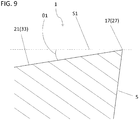
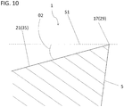
- the ridge line located on both sides of the concave part 25 corresponds to a first ridge line 27 and a second ridge line 29, a part of the first surface 3 which is located from the first ridge line 27 toward the midportion of the first surface 3 is a third region 33, and a part of the first surface 3 which is located from the second ridge line 29 toward the midportion of the first surface 3 is a fourth region 35.
- the third region 33 and the fourth region 35 may serve as a rake surface.
- a part of the first cutting edge 17 which is located more away from the first corner 9 than the concave part 25 corresponds to the first ridge line 27.
- a part of the first cutting edge 17 which is located closer to the first corner 9 than the concave part 25 corresponds to the second ridge line 29.
- a part of the first region 21 which is located along the first ridge line 27 corresponds to the third region 33.
- a part of the first region 21 which is located along the second ridge line 29 corresponds to the fourth region 35.
- An angle formed by the third region 33 and the reference plane S2 orthogonal to the central axis P of the insert 1 is a first angle ⁇ 1.
- An angle formed by the reference plane S1 and the fourth region 35 is a second angle ⁇ 2.
- a value of the first angle ⁇ 1 may be identical with or different from a value of the second angle ⁇ 2.
- the second angle ⁇ 2 is larger than the first angle ⁇ 1 in one embodiment illustrated in FIGs. 9 and 10 .
- the part of the chip bent by the concave part 25 tends to be easily divided apart due to velocity differences between chips flowing through the third region 33 and the chips flowing through the fourth region 35.
- the first ridge line 27 and the second ridge line 29 may be located on an imaginary straight line.
- an imaginary extension line L1 of the first ridge line 27 may intersect with an imaginary extension line L2 of the second ridge line 29 as in the embodiment illustrated in FIG. 6 .
- a portion indicated by an imaginary straight line L3 that connects an intersection point of the concave part 25 and the first ridge line 27 and an intersection point of the concave part 25 and the second ridge line 29 is an opening of the concave part 25 in the front view of the second surface 5. If the imaginary extension line L1 is located closer to the bottom portion of the concave part 25 than the opening as illustrated in FIG. 6 , a ridge portion where the concave 25 intersects with the first ridge line 27 has a large angle, and a large cutting load is therefore less likely to be concentrated at the ridge part. Consequently, the insert 1 is less subject to fractures, thus leading to enhanced durability of the insert 1.
- FIG. 11 is an enlarged view of a region corresponding to FIG. 6 in the inert 1 in one of the embodiments.
- the imaginary extension line L2 is located further away from the bottom portion of the concave part 25 than the opening as illustrated in FIG. 11 , a ridge portion where the concave 25 intersects with the second ridge line 29 has a small angle. Hence, the part of the chips which flows through the fourth region 35 is more likely to be bent than the part of the chips which flows through the concave 25. The chips are therefore more likely to be divided apart.
- the imaginary extension line L2 is located closer to the bottom portion of the concave part 25 than the opening, a ridge portion where the concave 25 intersects with the second ridge line 29 has a large angle. Hence, a large cutting load is less likely to be concentrated at the ridge part. The insert 1 is therefore less subject to fractures, thus leading to enhanced durability of the insert 1.
- the imaginary extension line L1 intersects with the imaginary extension line L2, and the imaginary extension line L1 and the imaginary extension line L2 are located further away from the bottom portion of the concave part 25 than the opening. In this case, chips are more likely to be divided apart, thus leading to more improved chip discharge performance.
- a length of the first ridge line 27 and a length of the second ridge line 29 are not limited to a specific value.
- the first ridge line 27 may have the same length as the second ridge line 29, or alternatively, the length of the first ridge line 27 may be different from the length of the second ridge line 29.
- cemented carbide or cermet is usable as a material of the insert 1.
- composition of the cemented carbide include WC-Co, WC-TiC-Co and WC-TiC-TaC-Co.
- the WC-Co is produced by adding cobalt (Co) powder to tungsten carbide (WC), followed by sintering.
- the WC-TiC-Co is produced by adding titanium carbide (TiC) to WC-Co.
- the WC-TiC-TaC-Co is produced by adding tantalum carbide (TaC) to WC-TiC-Co.
- the cermet is a sintered composite material obtainable by compositing metal into a ceramic component.
- Examples of the cermet include ones which are composed mainly of a titanium compound, such as titanium carbide (TiC) or titanium nitride (TiN).
- a surface of the insert 1 may be coated with a coating film by using a chemical vapor deposition (CVD) method or a physical vapor deposition (PVD) method.
- CVD chemical vapor deposition
- PVD physical vapor deposition
- examples of composition of the coating film include titanium carbide (TiC), titanium nitride (TiN), titanium carbonitride (TiCN) and alumina (Al 2 O 3 ).
- the insert 1' may include configurations similar to those in the insert 1. Descriptions of the similar configurations may be omitted in some cases.
- the insert 1' in one of the embodiments includes a first surface 3 (an upper surface in FIG. 12 ), a second surface 5 (a side surface in FIG. 12 ), and a ridge line 7 where the first surface 3 intersects with the second surface 5.
- the first surface 3 has a polygonal shape, and the first surface 3 has an approximately hexagonal shape in the embodiment illustrated in FIG. 13 . Accordingly, the first surface 3 includes six corners and six sides.
- the first surface 3 includes a first corner 9, and a first side 11 and a second side 13 each extended from the first corner 9.
- the first corner 9 is one of the six corners included in the first surface 3 in FIG. 13 .
- the first side 11 and the second side 13 are two of the six sides included in the first surface 3.
- the first surface 3 may have an approximately polygonal shape and need not be a strict polygonal shape.
- the sides in the first surface 3 having the polygonal shape need not have a strict straight line shape or, alternatively, these sides may have, for example, a convex curvilinear shape or concave curvilinear shape.
- the corners in the first surface 3 having the polygonal shape are not limited to a structure formed by intersection of the two straight lines, but may have, for example, an outwardly rounded shape.
- the shape of the first surface 3 is not limited to the above configuration. There is no problem even if the first surface 3 has a quadrangular shape, pentagonal shape or octagonal shape instead of the hexagonal shape.
- the insert 1' of the embodiment includes a cutting edge located on at least a part of the ridge line 7 in the present embodiment.
- the ridge line 7 includes a corner cutting edge 15 located on the first corner 9, a first cutting edge 17 located on at least a part of the first side 11, and a second cutting edge 19 located on at least the second side 13.
- the first cutting edge 17 may be located on only the part or the whole of the first side 11.
- the second cutting edge 19 may be located on only the part or the whole of the second side 13.
- a so-called honing process may be applied to the corner cutting edge 15, the first cutting edge 17 and the second cutting edge 19.
- the ridge line 7 where the first surface 3 intersects with the second surface 5 may not be a strict line shape obtained by intersection of the two surfaces.
- the first surface 3 also includes a first region 21 located from the first cutting edge 17 toward a midportion of the first surface 3, and a second region 23 located from the second cutting edge 19 toward the midportion of the first surface 3.
- the first region 21 and the second region 23 may serve as a rake surface.
- the first surface 3 includes a convex part 37 located in at least one of the first region 21 and the second region 23.
- the first surface 3 includes the convex part 37 extended from a side of the ridge line 7 toward the midportion of the first surface 3 in FIGs. 12 to 14 .
- the insert 1 includes the concave part 25 in the above embodiment, while the insert 1' includes the convex part 37 in the present embodiment as a configuration corresponding to the concave part 25.
- FIGs. 12 to 14 illustrate one embodiment in which the convex part 37 is located in the first region 21.
- the chips are divided apart along a chip extending direction.
- the chips so divided apart have a small width.
- the chips having the small width tend to be curled while being grazed on the first surface 3.
- the curled chips tend to be well divided apart.
- the chips are less likely to extend long because the chips are divided apart. This leads to good discharge of the chips. Chip clogging is less likely to occur because of good chip discharge performance. Additionally, a machined surface is less susceptible to damage due to the chips.
- chips may be divided apart in a direction orthogonal to the chip extending direction. This is because the chips become less likely to be curled due to bending by the contact with the convex part 37.
- the chips less likely to be curled are further bent in the direction orthogonal to the chip extending direction.
- the chips tend to be divided apart from a bent portion in the direction orthogonal to the chip extending direction. In other words, the chips are less likely to be curled and are divided apart at short intervals in the chip extending direction. Thus, the chips thus divided in short lengths tend to be discharged easily.
- the convex part 37 is extended from a side of the ridge line 7 toward the midportion of the first surface 3, the convex part 37 serves as a chip flow guide, thereby contributing to a better chip discharge.
- a portion having a maximum length N3 may be expressed by 0.03 M1 to 0.24 M1 where M1 is a length of the first cutting edge 17.
- a length N4 of the convex part 37 in a direction orthogonal to the second cutting edge 19 in cases where the convex part 37 is located in the second region 23.
- a portion having a maximum length N4 may be expressed by 0.03 M2 to 0.24 M2 where M2 is a length of the second cutting edge 19.
- the convex part 37 may be located in one of the first region 21 and the second region 23. Alternatively, the convex part 37 may be located in both the first region 21 and the second region 23. The convex part 37 is located in the first region 21 in the embodiment illustrated in FIG. 13 as described above.
- the first cutting edge 17 on the ridge line 7 is capable of serving as an inner peripheral cutting edge
- the second cutting edge 19 on the ridge line 7 is capable of serving as an outer peripheral cutting edge.
- the second cutting edge 19 is usable mainly during a face milling process.
- the first cutting edge 17 is also usable during a ramping process.
- Chips generated by the first cutting edge 17 serving as the inner peripheral cutting edge are relatively thin, and therefore, a flow of the chips generated by the first cutting edge 17 becomes unstable and are liable to extend long.
- the chips generated by the first cutting edge 17 can be stably divided apart if the convex part 37 is located in the first region 21.
- a good machined surface is obtainable if the convex part 37 is located in the second region 23.
- Chips generated by the second cutting edge 19 serving as the outer peripheral cutting edge are relatively thick, and the machined surface is therefore susceptible to damage upon occurrence of chip clogging.
- the chips generated by the second cutting edge 19 can be stably divided apart if the convex part 37 is located in the second region 23. Consequently, the chip clogging is less likely to occur, thus leading to the good machined surface.
- the convex part 37 may be located away from the ridge line 7, or alternatively, may include a part of the ridge line 7 as illustrated in FIG. 12 . If the convex part 37 includes the part of the ridge line 7, the first cutting edge 17 has a convex shape in the front view of the second surface 5. In this case, the convex part 37 extends from the ridge line 7 toward the midportion of the first surface 3.
- the first side 11 has a convex shape in the front view of the second surface 5, and therefore, chips tend to come into contact with the convex part 37. Consequently, the chips generated by the first cutting edge 17 tend to be bent and divided apart.
- the convex part 37 may include a part thereof whose width in a direction along the ridge line 7 becomes smaller as going away from the ridge line 7 in the front view of the first surface 3 as illustrated in FIG. 13 .
- the convex part 37 may include a part thereof whose width W2 in a direction along the first cutting edge 17 becomes smaller as going away from the first cutting edge 17 in the front view of the first surface 3.
- the convex part 37 may be configured so that the width W2 becomes smaller as a whole as going away from the first cutting edge 17.
- the convex part 37 includes the above configuration, stress concentration at a part of the convex part 37 which is in contact with the ridge line 7 can be relaxed to improve durability of the convex part 37.
- the length of the width W2 is not particularly limited.
- a portion having a maximum length W1 may be expressed by 0.1 M1 to 0.8 M1 where M1 is a length of the first cutting edge 17.
- the convex part 37 may include a part thereof where a height of the convex part 37 becomes smaller as going away from the ridge line 7 as illustrated in FIG. 15 . Further enhanced chip discharge performance is also attainable even if the convex part 37 is configured as described above. The chip discharge performance can be further enhanced because the chips are less likely to be accumulated in the convex part 37.
- the phrase "height becomes smaller” denotes that a distance D2 between a top portion of the convex part 37 and the reference plane S1 orthogonal to the central axis P of the insert becomes smaller as going away from the ridge line 7.
- the convex part 37 may include a part thereof where the distance between the top portion of the convex part 37 and the reference plane S1 is constant.
- the length of the distance D2 is not particularly limited.
- a portion having a maximum distance D2 may be expressed by 0.01 M1 to 0.4 M1 where M1 is the length of the first cutting edge 17.
- the ridge line located on both sides of the convex part 37 corresponds to a first ridge line 27' and a second ridge line 29'
- a part of the first surface 3 which is located from the first ridge line 27' toward the midportion of the first surface 3 is a third region 33'
- a part of the first surface 3 which is located from the second ridge line 29' toward the midportion of the first surface 3 is a fourth region 35'.
- the third region 33' and the fourth region 35' may serve as a rake surface.
- a part of the first cutting edge 17 which is located more away from the first corner 9 than the convex part 37 corresponds to the first ridge line 27'.
- a part of the first cutting edge 17 which is located closer to the first corner 9 than the convex part 37 corresponds to the second ridge line 29'.
- a part of the first region 21 which is located along the first ridge line 27' corresponds to the third region 33'.
- a part of the first region 21 which is located along the second ridge line 29' corresponds to the fourth region 35'.
- An angle formed by the third region 33' and the reference plane S1 orthogonal to the central axis P of the insert 1' is a first angle ⁇ 1'.
- An angle formed by the reference plane S1 and the fourth region 35' is a second angle ⁇ 2'.
- a value of the first angle ⁇ 1' may be identical with or different from a value of the second angle ⁇ 2'.
- the second angle ⁇ 2' may be larger than the first angle ⁇ 1'.
- the part of the chip bent by the convex part 37 tends to be torn off and divided apart due to velocity differences between chips flowing through the third region 33' and chips flowing through the fourth region 35' .
- the first ridge line 27' and the second ridge line 29' may be located on an imaginary straight line.
- an imaginary extension line L1 of the first ridge line 27' may intersect with an imaginary extension line L2 of the second ridge line 29' as in the embodiment illustrated in FIG. 16 .
- a portion indicated by an imaginary straight line L4 that connects an intersection point of the convex part 37 and the first ridge line 27' and an intersection point of the convex part 37 and the second ridge line 29' is a bottom portion of the convex part 37 in the front view of the second surface 5. If the imaginary extension line L1 is located closer to the top portion of the convex part 37 than the bottom portion of the convex part 37 as in the embodiment illustrated in FIG. 17 , chip clogging is less likely to occur in the vicinity of a boundary between the convex part 37 and the first ridge line 27'.
- FIG. 17 is an enlarged view of a region in the insert 1 in one of embodiments which corresponds to FIG. 16 .
- the imaginary extension line L1 is located further away from the top portion of the convex part 37 than the bottom portion of the convex part 37 as in the embodiment illustrated in FIG. 16 , chips are likely to be bent in the vicinity of the boundary between the convex part 37 and the first ridge line 27'. The chips are therefore more likely to be divided apart.
- the imaginary extension line L2 is located further away from the top portion of the convex part 37 than the bottom portion of the convex part 37, chips are likely to be bent in the vicinity of a boundary between the convex part 37 and the second ridge line 29'. The chips are therefore more likely to be divided apart.
- the imaginary extension line L1 intersects with the imaginary extension line L2, and the imaginary extension line L1 and the imaginary extension line L2 are located closer to the top portion of the convex part 37 than the bottom portion of the convex part 37. If the imaginary extension line L1 and the imaginary extension line L2 are located as described above, chip clogging is much less likely to occur in the vicinity of the boundary between the concave part 37 and the first ridge line 27' and in the vicinity of the boundary between the convex part 37 and the second ridge line 29'.
- a length of the first ridge line 27' and a length of the second ridge line 29' are not limited to a specific value.
- the first ridge line 27' may have the same length as the second ridge line 29'.
- the length of the first ridge line 27' may be different from the length of the second ridge line 29'.
- FIGs. 18 and 19 illustrate a state in which the insert 1 illustrated in FIG. 1 is attached to an insert pocket 105 (hereinafter also referred to simply as "pocket 105") of a holder 103 by a screw 107.
- a rotation axis X of the cutting tool 101 is indicated by a two-dot chain line in FIG. 18 or the like.
- the cutting tool 101 of the embodiment is usable for a milling process.
- the cutting tool 101 has the rotation axis X1 and includes the holder 103 with a plurality of pockets 105 on an outer peripheral surface at a side of a front end of the cutting tool 101, and inserts represented by the foregoing embodiment which are individually attached to the pockets 105.
- the insert 1 in the above embodiment is illustrated as the inserts in FIGs. 18 and 19 .
- the holder 103 is a bar-shaped body extended from a first end (lower left end in FIG. 18 ) to a second end (upper right end in FIG. 18 ).
- the plurality of pockets 105 are located on an outer peripheral surface at a side of the first end of the holder 103.
- the pockets 105 are parts that respectively permit attachment of the inserts 1 and open into an outer peripheral surface and the first end of the holder 103.
- the pockets 105 may be disposed at equal or unequal intervals along a rotation direction Y of the rotation axis X.
- the holder 103 includes the pockets 103 formed therein, and therefore does not have a strict cylindrical shape.
- Each of the inserts 1 is attachable to the pockets 105 by the screw 107. That is, the insert 1 is attachable to the holder 103 by inserting the screw 107 into a through hole of the insert 1, and by inserting a front end of the screw 107 into a screw hole formed in the pocket 105 so as to fix the screw 107 to the screw hole.
- the machined product is manufacturable by carrying out a cutting process of a workpiece.
- the method for manufacturing a machined product in the embodiment includes the following steps:
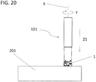
- the rotary tool 101 is rotated around the rotation axis X and in the rotation direction Y, and the cutting tool 101 is relatively brought near the workpiece 201 as illustrated in FIG. 20 .
- the workpiece 201 is cut out by bringing at least one of the first cutting edge and the second cutting edge in the cutting tool 101 being rotated into contact with the workpiece 201 as illustrated in FIG. 21 .
- the cutting tool 101 is then relatively moved away from the workpiece 201 as illustrated in FIG. 22 .
- a region of the workpiece 201 cut out by the cutting tool 101 is indicated by slant lines in FIGs. 21 and 22 .
- the cutting tool 101 is brought near the workpiece 201 by being moved in a Z1 direction along the rotation axis X in a state in which the workpiece 201 is fixed and the cutting tool 101 is rotated.
- the workpiece 201 is cut out by bringing at least one of the corner cutting edge, the first cutting edge and the second cutting edge in the cutting tool 101 into contact with the workpiece 201 while the cutting tool 101 being rotated is moved in a Z2 direction.
- the cutting tool 101 being rotated is moved away by being moved in a Z3 direction.
- the Z2 direction is not a direction orthogonal to the Z1 direction but a direction inclined relative to the Z1 direction. If the Z2 direction is thus inclined relative to the Z1 direction, a ramping process can be carried out. If the Z2 direction is a direction orthogonal to the Z1 direction, a flattening process can be carried out.
- the cutting tool 101 is brought into contact with the workpiece 201, or the cutting tool 101 is moved away from the workpiece 201 by moving the cutting tool 101 in the individual steps. It is, of course, not intended to limit to this embodiment.
- the workpiece 201 may be brought near the cutting tool 101 in the step (1). Similarly, the workpiece 201 may be moved away from the cutting tool 101 in the step (3). If desired to continue the cutting process, the step of bringing the cutting edges in the cutting tool 101 into contact with different portions of the workpiece 201 may be repeated while keeping the cutting tool 101 rotated.
- Examples of material of the workpiece 201 include carbon steel, alloy steel, stainless steel, cast iron and nonferrous metals.
Landscapes
- Engineering & Computer Science (AREA)
- Mechanical Engineering (AREA)
- Milling Processes (AREA)
- Cutting Tools, Boring Holders, And Turrets (AREA)
Applications Claiming Priority (2)
| Application Number | Priority Date | Filing Date | Title |
|---|---|---|---|
| JP2017160268 | 2017-08-23 | ||
| PCT/JP2018/031166 WO2019039547A1 (ja) | 2017-08-23 | 2018-08-23 | インサート |
Publications (2)
| Publication Number | Publication Date |
|---|---|
| EP3674023A1 true EP3674023A1 (de) | 2020-07-01 |
| EP3674023A4 EP3674023A4 (de) | 2021-05-26 |
Family
ID=65438956
Family Applications (1)
| Application Number | Title | Priority Date | Filing Date |
|---|---|---|---|
| EP18848561.9A Pending EP3674023A4 (de) | 2017-08-23 | 2018-08-23 | Einsatz |
Country Status (5)
| Country | Link |
|---|---|
| US (2) | US11325195B2 (de) |
| EP (1) | EP3674023A4 (de) |
| JP (1) | JP7116730B2 (de) |
| CN (1) | CN110997205B (de) |
| WO (1) | WO2019039547A1 (de) |
Families Citing this family (5)
| Publication number | Priority date | Publication date | Assignee | Title |
|---|---|---|---|---|
| EP3556498B1 (de) * | 2018-04-16 | 2021-02-17 | Seco Tools Ab | Schneideeinsatz und fräswerkzeug |
| JP6507355B1 (ja) * | 2018-06-19 | 2019-05-08 | 株式会社タンガロイ | 切削インサート及び切削工具 |
| US12036614B2 (en) * | 2019-03-27 | 2024-07-16 | Sumitomo Electric Hardmetal Corp. | Cutting insert |
| JP6957827B2 (ja) * | 2019-03-27 | 2021-11-02 | 住友電工ハードメタル株式会社 | 切削インサート |
| CN114905072B (zh) * | 2021-02-10 | 2024-01-30 | 株式会社泰珂洛 | 切削刀片以及配备该切削刀片的切削工具 |
Family Cites Families (40)
| Publication number | Priority date | Publication date | Assignee | Title |
|---|---|---|---|---|
| SE7710434L (sv) * | 1977-09-19 | 1979-03-20 | Sandvik Ab | Sker for spanskerande bearbetning |
| CA1170821A (en) * | 1980-08-27 | 1984-07-17 | Donald W. Warren | Cutting insert |
| US4755086A (en) * | 1987-10-23 | 1988-07-05 | Gte Valenite Corporation | Cutting insert |
| DE4141368A1 (de) | 1991-12-14 | 1993-06-17 | Krupp Widia Gmbh | Schneideinsatz |
| IL108995A (en) * | 1994-03-16 | 1996-12-05 | Iscar Ltd | Exchangeable cutting insert |
| JPH0871834A (ja) | 1994-09-05 | 1996-03-19 | Mitsubishi Materials Corp | スローアウェイチップ |
| SE509219C2 (sv) * | 1994-10-21 | 1998-12-21 | Sandvik Ab | Frässkär |
| EP0796162B1 (de) | 1994-12-10 | 1998-04-15 | KENNAMETAL HERTEL AG Werkzeuge + Hartstoffe | Bohrwerkzeug für bohrungen in metallvollmaterial |
| SE512040C2 (sv) * | 1998-05-06 | 2000-01-17 | Sandvik Ab | Vändskär för pinnfräsar |
| SE514032C2 (sv) * | 1998-09-08 | 2000-12-11 | Seco Tools Ab | Verktyg och skär för fräsning |
| US6186705B1 (en) * | 1999-02-23 | 2001-02-13 | Ingersoll Cutting Tool Company | Cutting insert with chip control |
| JP2001025907A (ja) | 1999-07-09 | 2001-01-30 | Mitsubishi Materials Corp | スローアウェイチップ |
| JP2001212704A (ja) * | 2000-01-31 | 2001-08-07 | Ngk Spark Plug Co Ltd | スローアウェイチップ |
| JP3483859B2 (ja) | 2001-03-06 | 2004-01-06 | オーエスジー株式会社 | スローアウェイ式チップ、及び、そのスローアウェイ式チップが装着されるフライス工具 |
| US6530726B2 (en) * | 2001-04-04 | 2003-03-11 | Kennametal Inc. | Cutting insert having improved cutting |
| JP4304935B2 (ja) * | 2002-03-11 | 2009-07-29 | 三菱マテリアル株式会社 | 切削工具及びスローアウェイチップ |
| JP3951766B2 (ja) * | 2002-03-20 | 2007-08-01 | 三菱マテリアル株式会社 | スローアウェイチップおよびスローアウェイ式切削工具 |
| US7771142B2 (en) * | 2003-05-09 | 2010-08-10 | Kennametal Inc. | Cutting insert with elliptical cutting edge |
| DE10338784B4 (de) * | 2003-08-23 | 2005-08-25 | Depo Gmbh & Co.Kg. | Schneidplatte für einen Fingerfräser |
| US7040844B1 (en) * | 2005-03-08 | 2006-05-09 | Mitsubishi Materials Corporation | Throwaway insert and throwaway-type rotary cutting tool |
| JP2007044779A (ja) * | 2005-08-08 | 2007-02-22 | Sumitomo Electric Hardmetal Corp | スローアウェイチップ及びそれを用いたミーリングカッタ |
| JP2007044782A (ja) * | 2005-08-08 | 2007-02-22 | Sumitomo Electric Hardmetal Corp | スローアウェイチップ及びそれを用いたミーリングカッタ |
| AT8743U1 (de) * | 2005-10-19 | 2006-12-15 | Ceratizit Austria Gmbh | Fräswerkzeug |
| KR100854278B1 (ko) * | 2006-12-28 | 2008-08-26 | 한국야금 주식회사 | 다기능 절삭공구 |
| IL182100A (en) * | 2007-03-21 | 2010-11-30 | Taegutec India Ltd | Cutting insert for a milling cutter |
| IL182343A0 (en) * | 2007-04-01 | 2007-07-24 | Iscar Ltd | Cutting insert and tool for milling and ramping at high feed rates |
| JP4941082B2 (ja) | 2007-05-08 | 2012-05-30 | 株式会社タンガロイ | スローアウェイ式切削工具およびこれに装着される切刃チップ |
| SE531250C2 (sv) * | 2007-06-05 | 2009-02-03 | Sandvik Intellectual Property | Indexerbart hörnfrässkär |
| SE532742C2 (sv) * | 2008-05-13 | 2010-03-30 | Sandvik Intellectual Property | Frässkär med biegg snedställd i måttlig vinkel |
| CA2757400A1 (en) | 2009-04-02 | 2010-10-07 | Tungaloy Corporation | Cutting insert and cutting edge replaceable cutting tool |
| KR101097658B1 (ko) * | 2009-05-29 | 2011-12-22 | 대구텍 유한회사 | 절삭 삽입체 |
| KR101296216B1 (ko) * | 2010-12-29 | 2013-08-13 | 한국야금 주식회사 | 양면사용 타입의 절삭인서트 |
| CN107297531B (zh) * | 2011-10-31 | 2019-11-22 | 京瓷株式会社 | 切削镶刀 |
| CN103619518B (zh) * | 2011-11-25 | 2016-08-17 | 住友电工硬质合金株式会社 | 用于铣削的可转位切削刀片 |
| CN103447591B (zh) * | 2012-05-28 | 2020-02-28 | 钴碳化钨硬质合金印度有限公司 | 四角形的可转位的钻头镶片 |
| US10245659B2 (en) * | 2014-06-27 | 2019-04-02 | Kyocera Corporation | Cutting insert, cutting tool, and method for manufacturing machined product |
| EP3199282B1 (de) * | 2014-09-26 | 2020-07-29 | KYOCERA Corporation | Schneideinsatz, schneidwerkzeug sowie verfahren zur herstellung eines zerschnittenen artikels |
| CN107073604B (zh) | 2014-11-27 | 2019-07-30 | 株式会社泰珂洛 | 切削刀片及刀头更换式旋转切削工具 |
| CN107405702B (zh) * | 2015-05-19 | 2019-09-27 | 株式会社泰珂洛 | 工具体以及切削工具 |
| JP5967330B1 (ja) | 2015-09-25 | 2016-08-10 | 三菱日立ツール株式会社 | 切削インサート、及び刃先交換式回転切削工具 |
-
2018
- 2018-08-23 WO PCT/JP2018/031166 patent/WO2019039547A1/ja not_active Ceased
- 2018-08-23 CN CN201880054120.6A patent/CN110997205B/zh active Active
- 2018-08-23 EP EP18848561.9A patent/EP3674023A4/de active Pending
- 2018-08-23 US US16/640,376 patent/US11325195B2/en active Active
- 2018-08-23 JP JP2019537678A patent/JP7116730B2/ja active Active
-
2022
- 2022-04-07 US US17/715,373 patent/US11666977B2/en active Active
Also Published As
| Publication number | Publication date |
|---|---|
| US11666977B2 (en) | 2023-06-06 |
| US11325195B2 (en) | 2022-05-10 |
| JPWO2019039547A1 (ja) | 2020-07-30 |
| CN110997205A (zh) | 2020-04-10 |
| JP7116730B2 (ja) | 2022-08-10 |
| US20220226913A1 (en) | 2022-07-21 |
| WO2019039547A1 (ja) | 2019-02-28 |
| EP3674023A4 (de) | 2021-05-26 |
| US20200361010A1 (en) | 2020-11-19 |
| CN110997205B (zh) | 2022-04-26 |
Similar Documents
| Publication | Publication Date | Title |
|---|---|---|
| US11666977B2 (en) | Insert | |
| US10099294B2 (en) | Cutting insert, cutting tool, and method for manufacturing machined product | |
| EP3213841A1 (de) | Halter, schneideinsatz und verfahren zur herstellung eines zerschnittenen artikels | |
| EP2962795A1 (de) | Schneideinsatz, schneidwerkzeug und verfahren zur herstellung eines schneidwerkstücks | |
| EP3072617B1 (de) | Schneideinsatz, schneidwerkzeug sowie verfahren zur herstellung eines zerschnittenen artikels | |
| JP6122486B2 (ja) | 切削インサート、切削工具および切削加工物の製造方法 | |
| JP6995973B2 (ja) | 切削工具及び切削加工物の製造方法 | |
| JPWO2019065525A1 (ja) | 切削インサート、切削工具及び切削加工物の製造方法 | |
| JP6711842B2 (ja) | 切削インサート、切削工具及び切削加工物の製造方法 | |
| US11260458B2 (en) | Cutting insert, cutting tool and method for manufacturing machined product | |
| US10413978B2 (en) | Cutting tool and method for manufacturing cut workpiece | |
| CN107614174B (zh) | 刀架、切削工具以及使用其的切削加工物的制造方法 | |
| US11517965B2 (en) | Cutting insert, cutting tool, and method of manufacturing machined product | |
| CN107708902A (zh) | 切削镶刀、切削工具以及使用该切削工具的切削加工物的制造方法 | |
| US11135659B2 (en) | Cutting tool holder, cutting tool, and method of manufacturing machined product | |
| US12186816B2 (en) | Cutting insert, cutting tool and method for manufacturing machined product | |
| US10987741B2 (en) | Cutting insert, cutting tool, and method for manufacturing machined product | |
| JP6717951B2 (ja) | 切削インサート、切削工具及び切削加工物の製造方法 | |
| JP5683208B2 (ja) | 切削インサートおよび切削工具ならびにそれを用いた被削材の切削方法 | |
| JP6877921B2 (ja) | 切削インサート、切削工具及び切削加工物の製造方法 | |
| JP6685532B2 (ja) | 切削インサート、切削工具及び切削加工物の製造方法 | |
| JP6449783B2 (ja) | 切削インサート、切削工具及び切削加工物の製造方法 |
Legal Events
| Date | Code | Title | Description |
|---|---|---|---|
| STAA | Information on the status of an ep patent application or granted ep patent |
Free format text: STATUS: THE INTERNATIONAL PUBLICATION HAS BEEN MADE |
|
| PUAI | Public reference made under article 153(3) epc to a published international application that has entered the european phase |
Free format text: ORIGINAL CODE: 0009012 |
|
| STAA | Information on the status of an ep patent application or granted ep patent |
Free format text: STATUS: REQUEST FOR EXAMINATION WAS MADE |
|
| 17P | Request for examination filed |
Effective date: 20200217 |
|
| AK | Designated contracting states |
Kind code of ref document: A1 Designated state(s): AL AT BE BG CH CY CZ DE DK EE ES FI FR GB GR HR HU IE IS IT LI LT LU LV MC MK MT NL NO PL PT RO RS SE SI SK SM TR |
|
| AX | Request for extension of the european patent |
Extension state: BA ME |
|
| DAV | Request for validation of the european patent (deleted) | ||
| DAX | Request for extension of the european patent (deleted) | ||
| A4 | Supplementary search report drawn up and despatched |
Effective date: 20210423 |
|
| RIC1 | Information provided on ipc code assigned before grant |
Ipc: B23C 5/20 20060101AFI20210419BHEP Ipc: B23C 5/10 20060101ALI20210419BHEP |
|
| P01 | Opt-out of the competence of the unified patent court (upc) registered |
Effective date: 20230505 |
|
| STAA | Information on the status of an ep patent application or granted ep patent |
Free format text: STATUS: EXAMINATION IS IN PROGRESS |
|
| 17Q | First examination report despatched |
Effective date: 20231211 |