EP3674083B1 - Procédé d'impression à jet d'encre recto verso sur textile utilisant une imprimante à jet d'encre numérique et textile - Google Patents
Procédé d'impression à jet d'encre recto verso sur textile utilisant une imprimante à jet d'encre numérique et textile Download PDFInfo
- Publication number
- EP3674083B1 EP3674083B1 EP18883245.5A EP18883245A EP3674083B1 EP 3674083 B1 EP3674083 B1 EP 3674083B1 EP 18883245 A EP18883245 A EP 18883245A EP 3674083 B1 EP3674083 B1 EP 3674083B1
- Authority
- EP
- European Patent Office
- Prior art keywords
- pattern
- textile
- target pattern
- inkjet printing
- unit
- Prior art date
- Legal status (The legal status is an assumption and is not a legal conclusion. Google has not performed a legal analysis and makes no representation as to the accuracy of the status listed.)
- Active
Links
Images


Classifications
-
- B—PERFORMING OPERATIONS; TRANSPORTING
- B41—PRINTING; LINING MACHINES; TYPEWRITERS; STAMPS
- B41J—TYPEWRITERS; SELECTIVE PRINTING MECHANISMS, i.e. MECHANISMS PRINTING OTHERWISE THAN FROM A FORME; CORRECTION OF TYPOGRAPHICAL ERRORS
- B41J15/00—Devices or arrangements of selective printing mechanisms, e.g. ink-jet printers or thermal printers, specially adapted for supporting or handling copy material in continuous form, e.g. webs
- B41J15/04—Supporting, feeding, or guiding devices; Mountings for web rolls or spindles
- B41J15/048—Conveyor belts or like feeding devices
-
- B—PERFORMING OPERATIONS; TRANSPORTING
- B41—PRINTING; LINING MACHINES; TYPEWRITERS; STAMPS
- B41J—TYPEWRITERS; SELECTIVE PRINTING MECHANISMS, i.e. MECHANISMS PRINTING OTHERWISE THAN FROM A FORME; CORRECTION OF TYPOGRAPHICAL ERRORS
- B41J2/00—Typewriters or selective printing mechanisms characterised by the printing or marking process for which they are designed
- B41J2/005—Typewriters or selective printing mechanisms characterised by the printing or marking process for which they are designed characterised by bringing liquid or particles selectively into contact with a printing material
- B41J2/01—Ink jet
-
- B—PERFORMING OPERATIONS; TRANSPORTING
- B41—PRINTING; LINING MACHINES; TYPEWRITERS; STAMPS
- B41J—TYPEWRITERS; SELECTIVE PRINTING MECHANISMS, i.e. MECHANISMS PRINTING OTHERWISE THAN FROM A FORME; CORRECTION OF TYPOGRAPHICAL ERRORS
- B41J29/00—Details of, or accessories for, typewriters or selective printing mechanisms not otherwise provided for
- B41J29/38—Drives, motors, controls or automatic cut-off devices for the entire printing mechanism
-
- B—PERFORMING OPERATIONS; TRANSPORTING
- B41—PRINTING; LINING MACHINES; TYPEWRITERS; STAMPS
- B41J—TYPEWRITERS; SELECTIVE PRINTING MECHANISMS, i.e. MECHANISMS PRINTING OTHERWISE THAN FROM A FORME; CORRECTION OF TYPOGRAPHICAL ERRORS
- B41J3/00—Typewriters or selective printing or marking mechanisms characterised by the purpose for which they are constructed
- B41J3/407—Typewriters or selective printing or marking mechanisms characterised by the purpose for which they are constructed for marking on special material
- B41J3/4078—Printing on textile
-
- B—PERFORMING OPERATIONS; TRANSPORTING
- B41—PRINTING; LINING MACHINES; TYPEWRITERS; STAMPS
- B41J—TYPEWRITERS; SELECTIVE PRINTING MECHANISMS, i.e. MECHANISMS PRINTING OTHERWISE THAN FROM A FORME; CORRECTION OF TYPOGRAPHICAL ERRORS
- B41J3/00—Typewriters or selective printing or marking mechanisms characterised by the purpose for which they are constructed
- B41J3/60—Typewriters or selective printing or marking mechanisms characterised by the purpose for which they are constructed for printing on both faces of the printing material
-
- D—TEXTILES; PAPER
- D06—TREATMENT OF TEXTILES OR THE LIKE; LAUNDERING; FLEXIBLE MATERIALS NOT OTHERWISE PROVIDED FOR
- D06P—DYEING OR PRINTING TEXTILES; DYEING LEATHER, FURS OR SOLID MACROMOLECULAR SUBSTANCES IN ANY FORM
- D06P5/00—Other features in dyeing or printing textiles, or dyeing leather, furs, or solid macromolecular substances in any form
- D06P5/30—Ink jet printing
-
- B—PERFORMING OPERATIONS; TRANSPORTING
- B41—PRINTING; LINING MACHINES; TYPEWRITERS; STAMPS
- B41J—TYPEWRITERS; SELECTIVE PRINTING MECHANISMS, i.e. MECHANISMS PRINTING OTHERWISE THAN FROM A FORME; CORRECTION OF TYPOGRAPHICAL ERRORS
- B41J2203/00—Embodiments of or processes related to the control of the printing process
- B41J2203/01—Inspecting a printed medium or a medium to be printed using a sensing device
Definitions
- the present disclosure relates to the field of textile printing, and in particular to a method for performing double-sided inkjet printing on the textile.
- a digital printing technology is developed, which is a high technology combining the machinery technology, the computer technology and the electronic information technology, and in which printing is performed via the digital technology.
- a great development is to be achieved in the textile printing industries.
- a current digital inkjet printer for performing digital printing generally includes a digital inkjet printing head, a guiding belt and a control system.
- a to-be-printed textile is arranged on the guiding belt, a target pattern is inputted to the control system, and the control system controls the digital inkjet printing head to print the target pattern on the textile.
- a front side and a back side of the textile it is required to print patterns on both sides of the textile, that is, a front side and a back side of the textile, to prevent an adverse effect to the character of the textile due to unaesthetic single-sided printed pattern.
- a pattern on the front side is superposed and aligned with that on the back side.
- a dye with good permeability is used to firstly print a pattern on one side of the textile, and the dye is permeated through the textile to form a pattern on the other side of the textile.
- the dye with good permeability may permeate across the textile, which may affect the character of the textile.
- Figure 5 schematically shows a target pattern.
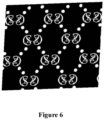
- Figure 6 schematically shows a textile a front side of which is printed and a back side of which is arranged upward.
- the textile is made of a flexible material, and the textile is easily distorted and deformed when being left aside, thus once being inverted, it is difficult to maintain the textile to be located in the same state as in the previous arrangement. In this case, it is impossible to ensure that the pattern on the front side is aligned with that on the back side just by printing the target pattern on the back side of the textile by the digital inkjet printer with a conventional method.
- a method for producing a double-sided inkjet printed textile of pure cotton is disclosed in a Chinese Patent Publication No. CN105926331A, published on September 7, 2016 , which includes the following steps 1) to 6).
- step 1) a pretreatment process is performed, in which a singeing process, a desizing process, a scouring process, an oxidation bleaching process and a mercerizing process are performed sequentially.
- a concentration of NaOH ranges from 180g/L to 320g/L.
- step 2) the textile is pretreated.
- the textile is sized with a padding method.
- a concentration of Na2CO3 ranges from 20g/L to 40g/L
- a concentration of carbamide ranges from 60g/L to 90g/L
- a concentration of a sizing material Lyoprint RD-HT ranges from 12g/L to 25g/L
- a concentration of a sizing material Lyoprint ATP-30 ranges from 15g/L to 25g/L
- a concentration of an antireducer LyoprintRG ranges from 2g/L to 15g/L
- a concentration of a permeability-reducing admixture HPU liq ranges from 6g/L to 12g/L.
- step 3 inkjet printing is performed on one side of the textile by a reactive inkjet printer, and the textile is dried and rolled orderly.
- step 4 the inkjet printing is performed on the other side of the textile by the reactive inkjet printer, and the textile is dried.
- step 5 the textile is steamed at 102 degree Celsius for 10 minutes to 14 minutes. After being steamed, the textile is washed, to remove loose colors and auxiliaries on the surfaces of the textile.
- step 6 the textile is softened and preshrunk.
- the method in the above application is only suitable for producing a textile having different patterns on the two sides, and cannot satisfy requirements for double-sided printed textile having patterns that are superposed and aligned with each other on the two sides.
- it has become a main index in determining the printing quality and aesthetics of a thin or translucent textile that whether a pattern on the front side is superposed and aligned with a pattern on the back side, which directly affects the character of a printed product.
- it is difficult to ensure alignment and superposition between the printed pattern on the front side and the printed pattern on the back side in the conventional printing technology.
- the patent application No. US2009284776 provides a process and apparatus for double-face ink-printing canvases for advertising light boxes.
- the process includes: disposing a print head at a side of an ink print workbench, an unprinted face of a reverse side of the canvas facing to the print head; disposing an inductor at the other side of the ink print workbench, a printed face of an obverse side of the canvas facing to the inductor; collecting image data of the printed face by the inductor during conveying the canvas and transmitting the image data to a signal processing device to process, and after time sequence processing, determining print positions on the unprinted face depending on results of the processing; and driving the print head to print on the determined print positions on the unprinted face by a print driving device, for achieving the double-faced ink print on the canvas for the advertising light boxes.
- the patent application No. CN107264028 discloses a recording apparatus (1), which includes a transport belt (10) that transports a medium (P), a recording unit (7) that performs recording on the medium supported by the transport belt, a plurality of imaging units (18a, 18b) provided on an upstream side and a downstream side in a transport direction of the medium, and configured to shoot a moving object including at least one of the transport belt and the medium, and a calculation unit that calculates a distance travelled by the transport belt in a predetermined time, on a basis of a position of a part of the moving object in an image picked up by the upstream imaging unit of the plurality of imaging units, and a position of the part of the moving object in an image picked up by the downstream imaging unit of the plurality of imaging units, the predetermined time after the image pickup by the upstream imaging unit.
- the patent application No. EP3056348 provides a digital type duplex printing method of printing images on both sides of a printing material such that a front-side image and a back-side image overlap each other.
- the digital type duplex printing method performs duplex printing with a digital type printer 10 which includes a print head 11 for performing printing by moving with respect to a printing material 50 and allows a printing jig 20 for setting the printing material 50 to be installed at a predetermined position such that the printing jig can be reversed.
- the printing material 50 is fixed in a stretched state to the printing jig 20, which is installed at the predetermined position.
- On the front surface of the printing material 50 a front-side image 31 and a front-side position detection mark 32 are printed.
- the printing jig 20 is inverted and is installed at the predetermined position.
- a back-side position detection mark 42 is printed on the back surface of the printing material 50.
- the back-side position detection mark 42 and the front-side position detection mark 32 are compared from any one of the front surface and the back surface, and the relative position of the back-side image to the front-side image of the printing material 50 is corrected on the basis of the comparison.
- a back-side image 41 is printed at the corrected relative position on the back surface of the printing material 50.
- a textile and a method for performing double-sided inkjet printing on the textile by a digital inkjet printer are provided according to the embodiments of the present disclosure, to achieve alignment and superposition between a pattern on a front side of the textile and a pattern on a back side of the textile during performing the double-sided inkjet printing on the textile, thereby significantly improving satisfaction of a customer on the textile.
- a method for performing double-sided inkjet printing on a textile by a digital inkjet printer is provided according to an embodiment of the present disclosure.
- the digital inkjet printer includes a digital inkjet printing head, a control system, a pattern collecting unit and a material feeding device.
- the digital inkjet printing head is configured to perform inkjet printing based on a target pattern.
- the control system includes a storage unit, a processing unit and a control unit.
- the storage unit is configured to store data.
- the processing unit is configured to receive, process and transmit data.
- the control unit is configured to control the processing unit to process the data and transmit a printing signal.
- the pattern collecting unit is configured to collect a pattern on the textile and transmit the collected pattern to the storage unit of the control system.
- the material feeding device includes a rack and a guiding belt arranged on the rack. A printing region is arranged on the guiding belt, and the digital inkjet printing head is arranged above the printing region.
- the method includes:
- the front side and “the back side” of the textile do not indicate a specific meaning. That is, one side of the textile is designated as a front side, and the other side of the textile is designated as a back side.
- the method further includes: performing a dry process on the textile.
- a grayscale process is performed on the mirrored target pattern, to obtain a grayscale template of the mirrored target pattern.
- the pattern collecting unit is a scanning device or a camera.
- the guiding belt is arranged with a heat sensitive adhesive or a pressure sensitive adhesive, to adhesively spread the textile flat on the guiding belt.
- the feature points are determined in a manner of 0.5 to 3 feature points every 6.4516 square centimeters (0.5 to 3 feature points per square inch) for aligning and positioning, and no feature point is determined at a region of a single color on the mirrored target pattern in which the mirrored target pattern has no change.
- the digital inkjet printer further includes a movable unit.
- the movable unit is configured to move in a direction perpendicular to a feeding direction of the guiding belt.
- the digital inkjet printing head and the pattern collecting unit are arranged on the movable unit.
- the pattern collecting unit is configured to move along with the movable unit and collect the back pattern in real time.
- the mirrored target pattern is aligned with the back pattern collected by the pattern collecting unit through manual observation. If it is determined that the mirrored target pattern is not aligned with the back pattern collected by the pattern collecting unit, the mirrored target pattern is adjusted manually through manual intervention, to align each of the feature points on the mirrored target pattern with the corresponding one feature point on the back pattern collected by the pattern collecting unit..
- the feature points are determined on the mirrored target pattern in a manner of one feature point every 6.4516 square centimeters (one feature point per square inch) at a position required to be aligned
- the target pattern is firstly printed onto the front side of the textile, then the textile is inverted.
- a back pattern on the back side of the textile is collected, which is formed by permeation of dye from the front side to the back side of the textile, and the mirrored target pattern is adjusted to be aligned with the collected back pattern, then the adjusted mirrored target pattern is printed.
- a digital inkjet printer includes a digital inkjet printing head 1, a control system 2, a pattern collecting unit 3 and a material feeding device 4.
- the digital inkjet printing head 1 is connected to the control system 2.
- the pattern collecting unit 3 is connected to the control system 2.
- the digital inkjet printer further includes a peripheral interface, a display screen, and an external port, which are not described in detail herein.
- Components shown in Figure 1 may be implemented as hardware, software or a combination of the hardware and the software. Each of the components shown in Figure 1 includes one or more signal processing and/or specific integrated circuits.
- the digital inkjet printing head 1 is configured to perform inkjet printing based on a target pattern.
- the control system 2 includes a storage unit 21, a processing unit 22 and a control unit 23.
- the storage unit 21 is configured to store data, which includes but is not limited to a target pattern inputted from an external device, a mirrored target pattern and a back pattern collected in a real time.
- the pattern collecting unit 32 is connected to the storage unit 21.
- the processing unit 22 is configured to receive, process and transmit data.
- the processing on data includes but is not limited to determining feature points, performing a mirroring process on the target pattern, obtaining the mirrored target pattern, aligning the mirrored target pattern with the collected back pattern and converting the target pattern into a grayscale template.
- the processing unit 22 is connected to the storage unit 21.
- the control unit 23 is configured to control the processing unit 22 to process data and transmit a printing signal.
- the control unit 23 is connected to the processing unit 22 and the digital inkjet printing head 1.
- the above components may be implemented as hardware, software or a combination of the hardware and the software. Each of the above components includes one or more
- the pattern collecting unit 3 is configured to collect a pattern on a textile and transmit the collected pattern to the storage unit 21 of the control system 2.
- the pattern collecting unit 3 may be a scanning device or a camera, as long as the pattern collecting unit 3 is capable of collecting a pattern on the textile.
- the material feeding device 4 includes a rack 41 and a guiding belt 42.
- the guiding belt 42 is arranged on the rack 41.
- a printing region is arranged on the guiding belt 42.
- the digital inkjet printing head 1 is arranged above the printing region.
- the guiding belt 42 is rotated by a power device to feed material.
- the power device may include a motor, a driving pulley, and a slave pulley.
- the motor is connected to the driving pulley and is configured to control the driving pulley to rotate.
- the guiding belt is looped over the driving pulley and the slave pulley, such that the slave pulley is rotated following the driving pulley.
- a heat sensitive adhesive or a pressure sensitive adhesive is arranged on the guiding belt 42, such that the textile may be spread flat and fixed on the guiding belt 42 when being arranged on the guiding belt 42, thereby preventing the textile from partially arching or crinkling, thus facilitating inkjet printing and ensuring accuracy of the inkjet printing.
- the digital inkjet printer further includes a movable unit 5.
- the movable unit 5 is configured to move in a direction perpendicular to a feeding direction of the guiding belt 42.
- the digital inkjet printing head 1 and the pattern collecting unit 3 are arranged on the movable unit 5. There is a certain distance between the pattern collecting unit 3 and the digital inkjet printing head 1 in the feeding direction of the guiding belt.
- the pattern collecting unit 3 is configured to move along with the movable unit and collects the pattern in real time. After one material feeding process is performed via the guiding belt 42, the digital inkjet printing head 1 performs inkjet printing once via the movable unit 5. In addition, the pattern collecting unit 3 collects a back pattern of the to-be-printed textile.
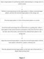
- a method for performing double-sided inkjet printing on a textile by the above digital inkjet printer includes the following steps 1) to 7).
- step 1) a textile is arranged.
- the textile is adhesively spread on the guiding belt 42 of the material feeding device 4.
- the guiding belt 42 is arranged with a heat sensitive adhesive or a pressure sensitive adhesive, to prevent the textile from moving or crinkling.
- step 2) a target pattern is inputted and printed.
- the target pattern is inputted to the storage unit 21 of the control system 2.
- the control unit 23 transmits a printing signal to the digital inkjet printing head 1, to print the stored target pattern on a front side of the textile by the digital inkjet printing head 1, and the textile is dried.
- the target pattern may be inputted before performing step 1).
- step 3 the textile is inverted and is arranged. After the target pattern is printed on the front side of the textile, the textile is inverted and is arranged on the guiding belt 42, such that a back side of the textile which is not printed is arranged toward the digital inkjet printing head 1.
- step 4 a mirroring process is performed on the target pattern.
- the processing unit 22 performs the mirroring process on the target pattern, to obtain a mirrored target pattern, and stores the mirrored target pattern in the storage unit 21.
- Step 4) may be performed at any time before the back side of the textile is printed.
- the mirror process may be performed on the target pattern by a computer outside this system, and the mirrored target pattern is duplicated in this system for subsequent use.
- a pattern on the textile is collected.
- the pattern collecting unit 3 collects a pattern on the back side of the textile which is not printed. This pattern is formed by permeation of dye from the front side of the textile to the back side of the textile, that is, a back pattern converted to the target pattern on the front side of the textile.
- the pattern collecting unit 3 transmits the collected back pattern to the storage unit 21.
- the mirrored target pattern is adjusted.
- the processing unit 22 adjusts the mirrored target pattern, to align the mirrored target pattern with the back pattern collected by the pattern collecting unit 3 (that is, feature points on the mirrored target pattern are paired with feature points on the collected back pattern and a feature point on the mirrored target pattern which is not aligned with a paired feature point on the collected back pattern is adjusted to be aligned with the paired feature point), such that an actually outputted target pattern is completely superposed with the collected pattern.
- the front side of the textile is printed and the back side of the textile is arranged upward on the guiding belt 42, the textile may be stretched and the pattern printed on the textile may be distorted or deformed.
- the processing unit 22 adjusts the mirrored target pattern based on the collected back pattern, to completely align a pattern on the back side of the textile with the pattern on the front side of the textile, thereby solving the problem in the conventional technology that it is impossible to exactly align a pattern on the back side of the textile with the pattern on the front side of the textile.
- step 7 the back side of the textile is printed.
- the adjusted mirrored target pattern is printed on the back side of the textile by the digital inkjet printing head 1.
- step 7) is performed, a dry process may be performed as needed.
- step 6 the processing unit 22 adjusts the mirrored target pattern through the following steps a, b and c.
- step a multiple feature points are determined on the mirrored target pattern.
- step b the processing unit 22 recognizes, on the back pattern collected by the pattern collecting unit 3, feature points each of which is located corresponding to one of the feature points on the mirrored target pattern and calculates a deviation between each of the feature points obtained in step b and the corresponding one feature point obtained in step a.
- step c the processing unit 22 adjusts the mirrored target pattern based on the deviation obtained in step b, to align each of the feature points on the mirrored target pattern with the corresponding one feature point on the back pattern collected by the pattern collecting unit 3, such that the mirrored target pattern is aligned with the back pattern collected by the pattern collecting unit 3.
- step 2) a dry process is performed on the textile, to prevent a case in which subsequent processes are performed before the dye is dried, which may affects the quality of the printing.
- the mirrored target pattern is converted into a grayscale template before determining the feature points on the mirrored target pattern, where a resolution of a processed pattern may be 150DPI or 300DPI.
- a resolution of a processed pattern may be 150DPI or 300DPI.
- pixels of the mirrored target pattern are reduced, thereby increasing a processing speed of the processing unit 22, thus improving operating efficiency.
- a color pattern may be directly used without being converted into the grayscale template, which may result in a slow recognizing speed, while have an advantage that a color pattern with any colors may be recognized (however, it is difficult to recognize a color pattern with certain colors).
- the feature points are determined in a manner of 0.5 to 3 feature points every 6.4516 square centimeters (0.5 to 3 feature points per square inch), and points that are easy to be aligned and positioned on the pattern are determined as features points, such as a point at a junction of lines or a corner of lines.
- step c if the deviation for aligning the mirrored target pattern with the back pattern collected by the pattern collecting unit 3 is large, it is determined whether the mirrored target pattern is aligned with the back pattern collected by the pattern collecting unit 3 through manual observation. If it is determined that the mirrored target pattern is not aligned with the back pattern collected by the pattern collecting unit 3, the mirrored target pattern is adjusted manually through manual intervention, to align each of the feature points on the mirrored target pattern with the corresponding one feature point on the back pattern collected by the pattern collecting unit 3. In order to align the feature point on the mirrored target pattern with the corresponding one feature point on the back pattern collected by the pattern collecting unit 3, the above manual observation process may be replaced by an automatic detection and an automatic skip process performed by the processing unit 22.
- the feature points are determined in a manner of one feature point every 6.4516 square centimeters (one feature point per square inch).
- a large number of feature points may lead to a high accuracy in alignment, while result in a large calculating amount.
- multiple mirrored target patterns may be spread flat and successively, to achieve continuous printing, thereby improving printing efficiency.
- a textile is provided in this embodiment.
- the textile has a front printed pattern and a back printed pattern.
- the front printed pattern is arranged on a front side of the textile and the back printed pattern is arranged on a back side of the textile, and the front printed pattern and the back printed pattern are aligned with each other.
- the front printed pattern and the back printed pattern are formed with the method for performing double-sided inkjet printing described in the second embodiment.
- the front printed pattern has feature points
- the back printed pattern has feature points located respectively corresponding to the feature points on the front printed pattern.
- the textile may be applied for producing silk scarves, scarves, cloths or the like.
Landscapes
- Engineering & Computer Science (AREA)
- Textile Engineering (AREA)
- Treatment Of Fiber Materials (AREA)
- Ink Jet (AREA)
- Coloring (AREA)
Claims (9)
- Procédé pour effectuer une impression à jet d'encre recto verso sur un textile par une imprimante à jet d'encre numérique, dans lequel l'imprimante à jet d'encre numérique comprend :une tête d'impression à jet d'encre numérique (1) configurée pour effectuer une impression à jet d'encre sur la base d'un motif cible ;un système de contrôle (2) comprenant une unité de stockage (21), une unité de traitement (22) et une unité de contrôle (23), dans lequel l'unité de stockage (21) est configurée pour stocker des données, l'unité de traitement (22) est configurée pour recevoir, traiter et transmettre des données, et l'unité de contrôle (23) est configurée pour contrôler l'unité de traitement pour traiter les données et transmettre un signal d'impression ;une unité de collecte de motif (3) configurée pour collecter un motif sur le textile ettransmettre le motif collecté à l'unité de stockage (21) du système de contrôle (2) ; etun dispositif d'alimentation en matériau (4) comprenant un support (41) et une courroie de guidage (42) disposée sur le support, dans lequel une région d'impression est disposée sur la courroie de guidage, et la tête d'impression à jet d'encre numérique (1) est disposée au-dessus de la région d'impression,dans lequel le procédé comprend :1) l'introduction d'un motif cible pour effectuer une impression à jet d'encre recto verso dans l'unité de stockage du système de contrôle ;2) la réalisation d'un processus de mise en miroir sur le motif cible pour obtenir un motif cible mis en miroir, et le stockage du motif cible mis en miroir dans l'unité de stockage ;3) la disposition du textile dans la région d'impression de la courroie de guidage, la transmission d'un signal d'impression à la tête d'impression à jet d'encre numérique par l'unité de contrôle, et l'impression du motif cible stocké sur une face avant du textile par la tête d'impression à jet d'encre numérique, pour former un motif imprimé avant,4) l'inversion du textile et la disposition du textile inversé sur la courroie de guidage, la collecte, par l'unité de collecte de motif, un motif arrière sur un côté arrière du textile qui est formé par perméation et est inversé en motif imprimé avant sur le côté avant du textile, et la transmission du motif arrière collecté à l'unité de stockage par l'unité de collecte de motif ;5) l'ajustement du motif cible mis en miroir obtenu à l'étape 2) par l'unité de traitement, pour aligner le motif cible mis en miroir avec le motif arrière collecté par l'unité de collecte de motif ; et6) l'impression du motif cible mis en miroir ajusté sur le côté arrière du textile par la tête d'impression à jet d'encre numérique,dans lequel, à l'étape 5), l'ajustement du motif cible mis en miroir par l'unité de traitement comprend :a. la détermination d'une pluralité de points caractéristiques sur le motif cible mis en miroir ;b. la reconnaissance, par l'unité de traitement et sur le motif arrière collecté par l'unité de collecte de motif, de points caractéristiques dont chacun est situé de manière à correspondre à l'un de la pluralité de points caractéristiques sur le motif cible mis en miroir, et le calcul d'un écart entre chacun des points caractéristiques obtenu à l'étape b et le point caractéristique correspondant obtenu à l'étape a ; etc. l'ajustement, par l'unité de traitement, du motif cible mis en miroir sur la base de l'écart obtenu à l'étape b, pour aligner chacun des points caractéristiques sur le motif cible mis en miroir avec le point caractéristique correspondant sur le motif arrière collecté par l'unité de collecte de motif, pour aligner le motif cible mis en miroir avec le motif arrière collecté par l'unité de collecte de motif.
- Procédé pour effectuer une impression à jet d'encre recto verso sur un textile par une imprimante numérique à jet d'encre selon la revendication 1, comprenant en outre : après l'étape 3), la réalisation d'un traitement à sec sur le textile.
- Procédé pour effectuer une impression à jet d'encre recto verso sur un textile par une imprimante numérique à jet d'encre selon la revendication 1, dans lequel à l'étape a, avant de déterminer les points caractéristiques sur le motif cible mis en miroir, le motif cible mis en miroir est converti en un modèle en niveaux de gris.
- Procédé pour effectuer une impression à jet d'encre recto verso sur un textile par une imprimante numérique à jet d'encre selon la revendication 1, dans lequel l'unité de collecte de motif (3) est un dispositif de numérisation ou une caméra.
- Procédé pour effectuer une impression à jet d'encre recto verso sur un textile par une imprimante numérique à jet d'encre selon la revendication 1, dans lequel la courroie de guidage (42) est agencée avec un adhésif thermosensible ou un adhésif sensible à la pression, pour étaler le textile à plat sur la courroie de guidage (42).
- Procédé pour effectuer une impression à jet d'encre recto verso sur un textile par une imprimante numérique à jet d'encre selon la revendication 1, dans lequel à l'étape a, les points caractéristiques sont déterminés à raison de 0,5 à 3 points caractéristiques par 6,4516 centimètres carrés (0,5 à 3 points caractéristiques par pouce carré) pour l'alignement et le positionnement, et aucun point caractéristique n'est déterminé au niveau d'une région d'une seule couleur sur le motif cible mis en miroir dans laquelle le motif cible mis en miroir ne présente aucun changement.
- Procédé pour effectuer une impression à jet d'encre recto verso sur un textile par une imprimante à jet d'encre numérique selon la revendication 1, dans lequel l'imprimante à jet d'encre numérique comprend en outre une unité mobile (5) configurée pour être mobile dans une direction perpendiculaire à une direction d'alimentation de la courroie de guidage (42), et dans lequel
la tête d'impression à jet d'encre numérique (1) et l'unité de collecte de motif (3) sont disposées sur l'unité mobile (5), et l'unité de collecte de motif (3) est configurée pour se déplacer avec l'unité mobile (5) et collecter le motif arrière en temps réel. - Procédé pour effectuer une impression à jet d'encre recto verso sur un textile par une imprimante numérique à jet d'encre selon la revendication 1, dans lequel à l'étape c, dans le cas où l'écart pour aligner le motif cible mis en miroir avec le motif arrière collecté par l'unité de collecte de motif est supérieur à une valeur prédéfinie, il est déterminé si le motif cible mis en miroir est aligné avec le motif arrière collecté par l'unité de collecte de motif par observation manuelle,
s'il est déterminé que le motif cible mis en miroir n'est pas aligné avec le motif arrière collecté par l'unité de collecte de motif, le motif cible mis en miroir est ajusté manuellement par intervention manuelle, pour aligner chacun des points caractéristiques sur le motif cible mis en miroir avec le point caractéristique correspondant sur le motif arrière collecté par l'unité de collecte de motif. - Procédé pour effectuer une impression à jet d'encre recto verso sur un textile par une imprimante numérique à jet d'encre selon la revendication 6, dans lequel à l'étape a, les points caractéristiques sont déterminés à raison d'un point caractéristique par 6,4516 centimètres carrés (un point caractéristique par pouce carré) à une position devant être alignée.
Applications Claiming Priority (2)
| Application Number | Priority Date | Filing Date | Title |
|---|---|---|---|
| CN201711248858.XA CN108032620B (zh) | 2017-12-01 | 2017-12-01 | 利用数码喷印机的纺织品的双面喷墨印花方法及纺织品 |
| PCT/CN2018/118878 WO2019105482A1 (fr) | 2017-12-01 | 2018-12-03 | Procédé d'impression à jet d'encre recto verso sur textile utilisant une imprimante à jet d'encre numérique et textile |
Publications (4)
| Publication Number | Publication Date |
|---|---|
| EP3674083A1 EP3674083A1 (fr) | 2020-07-01 |
| EP3674083A4 EP3674083A4 (fr) | 2021-05-05 |
| EP3674083B1 true EP3674083B1 (fr) | 2023-11-22 |
| EP3674083C0 EP3674083C0 (fr) | 2023-11-22 |
Family
ID=62094990
Family Applications (1)
| Application Number | Title | Priority Date | Filing Date |
|---|---|---|---|
| EP18883245.5A Active EP3674083B1 (fr) | 2017-12-01 | 2018-12-03 | Procédé d'impression à jet d'encre recto verso sur textile utilisant une imprimante à jet d'encre numérique et textile |
Country Status (4)
| Country | Link |
|---|---|
| EP (1) | EP3674083B1 (fr) |
| CN (1) | CN108032620B (fr) |
| ES (1) | ES2969656T3 (fr) |
| WO (1) | WO2019105482A1 (fr) |
Families Citing this family (17)
| Publication number | Priority date | Publication date | Assignee | Title |
|---|---|---|---|---|
| CN108032620B (zh) * | 2017-12-01 | 2019-09-03 | 杭州宏华数码科技股份有限公司 | 利用数码喷印机的纺织品的双面喷墨印花方法及纺织品 |
| CN109177526B (zh) * | 2018-09-25 | 2021-07-20 | 沈阳飞行船数码喷印设备有限公司 | 双面打印的方法和系统 |
| CN109177534A (zh) * | 2018-10-11 | 2019-01-11 | 杭州宏华数码科技股份有限公司 | 导带式数码印花机中的用于双面对花印花的图像摄录装置及摄录方法 |
| CN109177533A (zh) * | 2018-10-11 | 2019-01-11 | 杭州宏华数码科技股份有限公司 | 一种用于导带式印花机的双面对花印花的图像摄录装置及摄录方法 |
| CN109965413A (zh) * | 2019-03-20 | 2019-07-05 | 浙江理工大学 | 一种双面织印结合的丝绸围巾制作方法 |
| US20230145554A1 (en) * | 2019-10-21 | 2023-05-11 | Hewlett-Packard Development Company, L.P. | Substrate porosity determination |
| CN111815688B (zh) * | 2020-06-24 | 2022-10-21 | 杭州宏华数码科技股份有限公司 | 一种长线条图像的精准配准方法 |
| CN112123953B (zh) * | 2020-07-20 | 2022-06-21 | 沈阳飞行船数码喷印设备有限公司 | 双面打印方法 |
| CN113787839B (zh) * | 2021-09-18 | 2022-08-09 | 苏州工业园区鑫海胜电子有限公司 | 一种双面打印的方法及装置 |
| FR3129956B1 (fr) * | 2021-12-02 | 2024-04-19 | Neyret Textile Identification | Procédé d’impression sur un textile de laize étroite |
| CN114953745B (zh) * | 2022-07-28 | 2022-10-25 | 杭州宏华数码科技股份有限公司 | 用于控制喷印装置的方法、设备和介质 |
| US12539705B2 (en) | 2023-03-06 | 2026-02-03 | Global Textile Alliance Belgium | Textured fabric printing system and method |
| JP2025069689A (ja) * | 2023-10-18 | 2025-05-01 | セイコーエプソン株式会社 | 印刷装置及び印刷方法 |
| CN117818221B (zh) * | 2024-01-19 | 2024-07-23 | 绍兴永通印花有限公司 | 智能高速数码印花机及立体效果印花工艺 |
| CN120116630B (zh) * | 2024-04-25 | 2026-02-24 | 深圳市汉森软件股份有限公司 | 基于墨量优化的双面喷墨打印方法、装置及设备 |
| CN118205320B (zh) * | 2024-04-30 | 2025-06-10 | 成都宸亿轩科技有限公司 | 一种基于视觉感知的双面喷对位打印控制方法及装置 |
| CN119636274A (zh) * | 2024-12-04 | 2025-03-18 | 广东宁为新创科技发展有限公司 | 一种数码印刷方法 |
Citations (1)
| Publication number | Priority date | Publication date | Assignee | Title |
|---|---|---|---|---|
| EP3056348B1 (fr) * | 2015-02-13 | 2018-11-28 | Mimaki Engineering Co., Ltd. | Procédé d'impression en duplex de type numérique |
Family Cites Families (17)
| Publication number | Priority date | Publication date | Assignee | Title |
|---|---|---|---|---|
| US6499822B1 (en) * | 1998-04-27 | 2002-12-31 | Canon Kabushiki Kaisha | Method and apparatus for forming an image on a recording medium with contraction and expansion properties |
| ATE352419T1 (de) * | 1999-03-10 | 2007-02-15 | Seiko Epson Corp | Einstellung der verschiebung der punktbildungslage unter verwendung von informationen, gemäss welcher nicht für jede pixeleinheit ein punkt gebildet werden muss |
| JP5147152B2 (ja) * | 2001-08-06 | 2013-02-20 | キヤノン株式会社 | 両面印字装置 |
| JP4041959B2 (ja) * | 2002-08-09 | 2008-02-06 | リコープリンティングシステムズ株式会社 | 印刷システムにおける印刷停止制御方式 |
| CN100382977C (zh) * | 2003-03-28 | 2008-04-23 | 梁健 | 高精度同步双面写真喷画机 |
| CN101164791A (zh) * | 2006-10-18 | 2008-04-23 | 梁健 | 同步双面数码印刷机 |
| CN101616806A (zh) * | 2007-01-29 | 2009-12-30 | 石刚 | 一种广告灯箱画布的双面喷绘方法和喷绘装置 |
| JP2011178035A (ja) * | 2010-03-01 | 2011-09-15 | Ricoh Co Ltd | 両面印刷システム、両面印刷方法、プログラム、並びに記録媒体 |
| CN103029455B (zh) * | 2011-09-30 | 2015-04-22 | 北大方正集团有限公司 | 喷墨印刷定位装置及其控制方法 |
| CN202878907U (zh) * | 2012-06-28 | 2013-04-17 | 深圳市润天智数字设备股份有限公司 | 一种喷绘机 |
| CN102729627A (zh) * | 2012-06-28 | 2012-10-17 | 深圳市润天智数字设备股份有限公司 | 一种双面镜像喷绘方法 |
| CN104924755B (zh) * | 2014-03-18 | 2016-06-22 | 梁健 | 一种同步单双面数码喷绘机及其绕布方法 |
| CN205255775U (zh) * | 2015-10-20 | 2016-05-25 | 杭州宏华数码科技股份有限公司 | 一种导带式喷墨印花机的闭环式导带步进控制系统 |
| CN106696482B (zh) * | 2015-11-18 | 2019-01-01 | 北大方正集团有限公司 | 打印控制方法和设备 |
| CN105926331A (zh) | 2016-04-01 | 2016-09-07 | 鲁丰织染有限公司 | 纯棉双面喷墨印花面料的制作方法 |
| JP2017185694A (ja) * | 2016-04-06 | 2017-10-12 | セイコーエプソン株式会社 | 記録装置及び搬送ベルトの移動量の算出方法 |
| CN108032620B (zh) * | 2017-12-01 | 2019-09-03 | 杭州宏华数码科技股份有限公司 | 利用数码喷印机的纺织品的双面喷墨印花方法及纺织品 |
-
2017
- 2017-12-01 CN CN201711248858.XA patent/CN108032620B/zh active Active
-
2018
- 2018-12-03 EP EP18883245.5A patent/EP3674083B1/fr active Active
- 2018-12-03 ES ES18883245T patent/ES2969656T3/es active Active
- 2018-12-03 WO PCT/CN2018/118878 patent/WO2019105482A1/fr not_active Ceased
Patent Citations (1)
| Publication number | Priority date | Publication date | Assignee | Title |
|---|---|---|---|---|
| EP3056348B1 (fr) * | 2015-02-13 | 2018-11-28 | Mimaki Engineering Co., Ltd. | Procédé d'impression en duplex de type numérique |
Also Published As
| Publication number | Publication date |
|---|---|
| EP3674083A1 (fr) | 2020-07-01 |
| CN108032620A (zh) | 2018-05-15 |
| CN108032620B (zh) | 2019-09-03 |
| EP3674083A4 (fr) | 2021-05-05 |
| EP3674083C0 (fr) | 2023-11-22 |
| ES2969656T3 (es) | 2024-05-21 |
| WO2019105482A1 (fr) | 2019-06-06 |
Similar Documents
| Publication | Publication Date | Title |
|---|---|---|
| EP3674083B1 (fr) | Procédé d'impression à jet d'encre recto verso sur textile utilisant une imprimante à jet d'encre numérique et textile | |
| EP3653391A1 (fr) | Procédé d'impression numérique précise pour un tissu au moyen d'une machine d'impression numérique et d'un tissu | |
| US6712444B2 (en) | Method and apparatus for forming an image on a recording medium with contraction and expansion properties | |
| CN113524927B (zh) | 双面打印的方法和系统 | |
| JP2003311938A (ja) | 印字ヘッド干渉物検出方法 | |
| US20110211011A1 (en) | Image forming apparatus | |
| JP6194499B2 (ja) | 印刷システムおよび印刷装置 | |
| CN112848679B (zh) | 印刷装置以及印刷方法 | |
| JP5911256B2 (ja) | プリント装置および検査方法 | |
| US20140037354A1 (en) | Print control method and continuous sheet for use therein | |
| CN108215516B (zh) | 图像形成装置、记录介质以及图像形成系统 | |
| CN112848678A (zh) | 印刷装置以及印刷方法 | |
| EP2839966B1 (fr) | Appareil de décharge liquide et procédé de décharge de liquide | |
| CN107009756B (zh) | 图像形成装置 | |
| JP2010135964A (ja) | 画像読取装置のドライバおよび画像読取方法 | |
| JP6499895B2 (ja) | 画像形成装置 | |
| JP2022052808A (ja) | 画像形成装置および画像形成装置の制御方法 | |
| JP6386825B2 (ja) | 印刷装置 | |
| CN112497919A (zh) | 印刷装置、印刷装置的控制方法以及存储介质 | |
| US20250036904A1 (en) | Printing marks on substrate edge | |
| US11727234B2 (en) | Performance of printing based on detected end portions of medium | |
| WO2024228074A1 (fr) | Identification de buses problématiques dans un système d'impression numérique | |
| CN109177533A (zh) | 一种用于导带式印花机的双面对花印花的图像摄录装置及摄录方法 | |
| JP6092677B2 (ja) | 印刷装置 | |
| EP4334136A1 (fr) | Système et procédé d'impression numérique |
Legal Events
| Date | Code | Title | Description |
|---|---|---|---|
| STAA | Information on the status of an ep patent application or granted ep patent |
Free format text: STATUS: THE INTERNATIONAL PUBLICATION HAS BEEN MADE |
|
| PUAI | Public reference made under article 153(3) epc to a published international application that has entered the european phase |
Free format text: ORIGINAL CODE: 0009012 |
|
| STAA | Information on the status of an ep patent application or granted ep patent |
Free format text: STATUS: REQUEST FOR EXAMINATION WAS MADE |
|
| 17P | Request for examination filed |
Effective date: 20200325 |
|
| AK | Designated contracting states |
Kind code of ref document: A1 Designated state(s): AL AT BE BG CH CY CZ DE DK EE ES FI FR GB GR HR HU IE IS IT LI LT LU LV MC MK MT NL NO PL PT RO RS SE SI SK SM TR |
|
| AX | Request for extension of the european patent |
Extension state: BA ME |
|
| DAV | Request for validation of the european patent (deleted) | ||
| DAX | Request for extension of the european patent (deleted) | ||
| A4 | Supplementary search report drawn up and despatched |
Effective date: 20210409 |
|
| RIC1 | Information provided on ipc code assigned before grant |
Ipc: B41J 11/00 20060101ALI20210401BHEP Ipc: B41J 3/60 20060101ALI20210401BHEP Ipc: B41J 3/407 20060101ALI20210401BHEP Ipc: D06P 5/30 20060101ALI20210401BHEP Ipc: B41J 29/38 20060101ALI20210401BHEP Ipc: B41J 2/01 20060101AFI20210401BHEP |
|
| STAA | Information on the status of an ep patent application or granted ep patent |
Free format text: STATUS: EXAMINATION IS IN PROGRESS |
|
| 17Q | First examination report despatched |
Effective date: 20220915 |
|
| GRAP | Despatch of communication of intention to grant a patent |
Free format text: ORIGINAL CODE: EPIDOSNIGR1 |
|
| STAA | Information on the status of an ep patent application or granted ep patent |
Free format text: STATUS: GRANT OF PATENT IS INTENDED |
|
| RIC1 | Information provided on ipc code assigned before grant |
Ipc: B41J 15/04 20060101ALI20230523BHEP Ipc: B41J 29/38 20060101ALI20230523BHEP Ipc: D06P 5/30 20060101ALI20230523BHEP Ipc: B41J 3/407 20060101ALI20230523BHEP Ipc: B41J 3/60 20060101ALI20230523BHEP Ipc: B41J 11/00 20060101ALI20230523BHEP Ipc: B41J 2/01 20060101AFI20230523BHEP |
|
| INTG | Intention to grant announced |
Effective date: 20230622 |
|
| GRAS | Grant fee paid |
Free format text: ORIGINAL CODE: EPIDOSNIGR3 |
|
| GRAA | (expected) grant |
Free format text: ORIGINAL CODE: 0009210 |
|
| STAA | Information on the status of an ep patent application or granted ep patent |
Free format text: STATUS: THE PATENT HAS BEEN GRANTED |
|
| AK | Designated contracting states |
Kind code of ref document: B1 Designated state(s): AL AT BE BG CH CY CZ DE DK EE ES FI FR GB GR HR HU IE IS IT LI LT LU LV MC MK MT NL NO PL PT RO RS SE SI SK SM TR |
|
| REG | Reference to a national code |
Ref country code: GB Ref legal event code: FG4D |
|
| REG | Reference to a national code |
Ref country code: CH Ref legal event code: EP |
|
| REG | Reference to a national code |
Ref country code: DE Ref legal event code: R096 Ref document number: 602018061624 Country of ref document: DE |
|
| REG | Reference to a national code |
Ref country code: IE Ref legal event code: FG4D |
|
| U01 | Request for unitary effect filed |
Effective date: 20231122 |
|
| U07 | Unitary effect registered |
Designated state(s): AT BE BG DE DK EE FI FR IT LT LU LV MT NL PT SE SI Effective date: 20231127 |
|
| U20 | Renewal fee for the european patent with unitary effect paid |
Year of fee payment: 6 Effective date: 20231201 |
|
| PG25 | Lapsed in a contracting state [announced via postgrant information from national office to epo] |
Ref country code: GR Free format text: LAPSE BECAUSE OF FAILURE TO SUBMIT A TRANSLATION OF THE DESCRIPTION OR TO PAY THE FEE WITHIN THE PRESCRIBED TIME-LIMIT Effective date: 20240223 |
|
| PG25 | Lapsed in a contracting state [announced via postgrant information from national office to epo] |
Ref country code: IS Free format text: LAPSE BECAUSE OF FAILURE TO SUBMIT A TRANSLATION OF THE DESCRIPTION OR TO PAY THE FEE WITHIN THE PRESCRIBED TIME-LIMIT Effective date: 20240322 |
|
| PG25 | Lapsed in a contracting state [announced via postgrant information from national office to epo] |
Ref country code: IS Free format text: LAPSE BECAUSE OF FAILURE TO SUBMIT A TRANSLATION OF THE DESCRIPTION OR TO PAY THE FEE WITHIN THE PRESCRIBED TIME-LIMIT Effective date: 20240322 Ref country code: GR Free format text: LAPSE BECAUSE OF FAILURE TO SUBMIT A TRANSLATION OF THE DESCRIPTION OR TO PAY THE FEE WITHIN THE PRESCRIBED TIME-LIMIT Effective date: 20240223 |
|
| REG | Reference to a national code |
Ref country code: ES Ref legal event code: FG2A Ref document number: 2969656 Country of ref document: ES Kind code of ref document: T3 Effective date: 20240521 |
|
| PG25 | Lapsed in a contracting state [announced via postgrant information from national office to epo] |
Ref country code: RS Free format text: LAPSE BECAUSE OF FAILURE TO SUBMIT A TRANSLATION OF THE DESCRIPTION OR TO PAY THE FEE WITHIN THE PRESCRIBED TIME-LIMIT Effective date: 20231122 Ref country code: PL Free format text: LAPSE BECAUSE OF FAILURE TO SUBMIT A TRANSLATION OF THE DESCRIPTION OR TO PAY THE FEE WITHIN THE PRESCRIBED TIME-LIMIT Effective date: 20231122 Ref country code: NO Free format text: LAPSE BECAUSE OF FAILURE TO SUBMIT A TRANSLATION OF THE DESCRIPTION OR TO PAY THE FEE WITHIN THE PRESCRIBED TIME-LIMIT Effective date: 20240222 Ref country code: HR Free format text: LAPSE BECAUSE OF FAILURE TO SUBMIT A TRANSLATION OF THE DESCRIPTION OR TO PAY THE FEE WITHIN THE PRESCRIBED TIME-LIMIT Effective date: 20231122 |
|
| PG25 | Lapsed in a contracting state [announced via postgrant information from national office to epo] |
Ref country code: CZ Free format text: LAPSE BECAUSE OF FAILURE TO SUBMIT A TRANSLATION OF THE DESCRIPTION OR TO PAY THE FEE WITHIN THE PRESCRIBED TIME-LIMIT Effective date: 20231122 |
|
| PG25 | Lapsed in a contracting state [announced via postgrant information from national office to epo] |
Ref country code: SK Free format text: LAPSE BECAUSE OF FAILURE TO SUBMIT A TRANSLATION OF THE DESCRIPTION OR TO PAY THE FEE WITHIN THE PRESCRIBED TIME-LIMIT Effective date: 20231122 |
|
| PG25 | Lapsed in a contracting state [announced via postgrant information from national office to epo] |
Ref country code: SM Free format text: LAPSE BECAUSE OF FAILURE TO SUBMIT A TRANSLATION OF THE DESCRIPTION OR TO PAY THE FEE WITHIN THE PRESCRIBED TIME-LIMIT Effective date: 20231122 Ref country code: SK Free format text: LAPSE BECAUSE OF FAILURE TO SUBMIT A TRANSLATION OF THE DESCRIPTION OR TO PAY THE FEE WITHIN THE PRESCRIBED TIME-LIMIT Effective date: 20231122 Ref country code: RO Free format text: LAPSE BECAUSE OF FAILURE TO SUBMIT A TRANSLATION OF THE DESCRIPTION OR TO PAY THE FEE WITHIN THE PRESCRIBED TIME-LIMIT Effective date: 20231122 Ref country code: CZ Free format text: LAPSE BECAUSE OF FAILURE TO SUBMIT A TRANSLATION OF THE DESCRIPTION OR TO PAY THE FEE WITHIN THE PRESCRIBED TIME-LIMIT Effective date: 20231122 |
|
| REG | Reference to a national code |
Ref country code: CH Ref legal event code: PL |
|
| REG | Reference to a national code |
Ref country code: DE Ref legal event code: R097 Ref document number: 602018061624 Country of ref document: DE |
|
| PG25 | Lapsed in a contracting state [announced via postgrant information from national office to epo] |
Ref country code: MC Free format text: LAPSE BECAUSE OF FAILURE TO SUBMIT A TRANSLATION OF THE DESCRIPTION OR TO PAY THE FEE WITHIN THE PRESCRIBED TIME-LIMIT Effective date: 20231122 |
|
| PG25 | Lapsed in a contracting state [announced via postgrant information from national office to epo] |
Ref country code: MC Free format text: LAPSE BECAUSE OF FAILURE TO SUBMIT A TRANSLATION OF THE DESCRIPTION OR TO PAY THE FEE WITHIN THE PRESCRIBED TIME-LIMIT Effective date: 20231122 |
|
| PLBE | No opposition filed within time limit |
Free format text: ORIGINAL CODE: 0009261 |
|
| STAA | Information on the status of an ep patent application or granted ep patent |
Free format text: STATUS: NO OPPOSITION FILED WITHIN TIME LIMIT |
|
| REG | Reference to a national code |
Ref country code: IE Ref legal event code: MM4A |
|
| PG25 | Lapsed in a contracting state [announced via postgrant information from national office to epo] |
Ref country code: IE Free format text: LAPSE BECAUSE OF NON-PAYMENT OF DUE FEES Effective date: 20231203 |
|
| PG25 | Lapsed in a contracting state [announced via postgrant information from national office to epo] |
Ref country code: CH Free format text: LAPSE BECAUSE OF NON-PAYMENT OF DUE FEES Effective date: 20231231 |
|
| GBPC | Gb: european patent ceased through non-payment of renewal fee |
Effective date: 20240222 |
|
| 26N | No opposition filed |
Effective date: 20240823 |
|
| PG25 | Lapsed in a contracting state [announced via postgrant information from national office to epo] |
Ref country code: IE Free format text: LAPSE BECAUSE OF NON-PAYMENT OF DUE FEES Effective date: 20231203 Ref country code: CH Free format text: LAPSE BECAUSE OF NON-PAYMENT OF DUE FEES Effective date: 20231231 |
|
| U20 | Renewal fee for the european patent with unitary effect paid |
Year of fee payment: 7 Effective date: 20241127 |
|
| PG25 | Lapsed in a contracting state [announced via postgrant information from national office to epo] |
Ref country code: GB Free format text: LAPSE BECAUSE OF NON-PAYMENT OF DUE FEES Effective date: 20240222 |
|
| PG25 | Lapsed in a contracting state [announced via postgrant information from national office to epo] |
Ref country code: GB Free format text: LAPSE BECAUSE OF NON-PAYMENT OF DUE FEES Effective date: 20240222 |
|
| PG25 | Lapsed in a contracting state [announced via postgrant information from national office to epo] |
Ref country code: CY Free format text: LAPSE BECAUSE OF FAILURE TO SUBMIT A TRANSLATION OF THE DESCRIPTION OR TO PAY THE FEE WITHIN THE PRESCRIBED TIME-LIMIT; INVALID AB INITIO Effective date: 20181203 |
|
| PG25 | Lapsed in a contracting state [announced via postgrant information from national office to epo] |
Ref country code: HU Free format text: LAPSE BECAUSE OF FAILURE TO SUBMIT A TRANSLATION OF THE DESCRIPTION OR TO PAY THE FEE WITHIN THE PRESCRIBED TIME-LIMIT; INVALID AB INITIO Effective date: 20181203 |
|
| PGFP | Annual fee paid to national office [announced via postgrant information from national office to epo] |
Ref country code: TR Payment date: 20251201 Year of fee payment: 8 |
|
| U20 | Renewal fee for the european patent with unitary effect paid |
Year of fee payment: 8 Effective date: 20251229 |
|
| PGFP | Annual fee paid to national office [announced via postgrant information from national office to epo] |
Ref country code: ES Payment date: 20260211 Year of fee payment: 8 |