EP3674272A1 - Beschichtungsmaterial für optische faser, beschichtete optische faser und verfahren zur herstellung einer beschichteten optischen faser - Google Patents
Beschichtungsmaterial für optische faser, beschichtete optische faser und verfahren zur herstellung einer beschichteten optischen faser Download PDFInfo
- Publication number
- EP3674272A1 EP3674272A1 EP18849000.7A EP18849000A EP3674272A1 EP 3674272 A1 EP3674272 A1 EP 3674272A1 EP 18849000 A EP18849000 A EP 18849000A EP 3674272 A1 EP3674272 A1 EP 3674272A1
- Authority
- EP
- European Patent Office
- Prior art keywords
- optical fiber
- coating material
- photoacid generator
- equal
- acid
- Prior art date
- Legal status (The legal status is an assumption and is not a legal conclusion. Google has not performed a legal analysis and makes no representation as to the accuracy of the status listed.)
- Pending
Links
- 239000013307 optical fiber Substances 0.000 title claims abstract description 177
- 239000000463 material Substances 0.000 title claims abstract description 146
- 239000011248 coating agent Substances 0.000 title claims abstract description 132
- 238000000576 coating method Methods 0.000 title claims abstract description 132
- 238000004519 manufacturing process Methods 0.000 title claims abstract description 41
- 239000002253 acid Substances 0.000 claims abstract description 158
- 239000011521 glass Substances 0.000 claims abstract description 92
- 239000011247 coating layer Substances 0.000 claims abstract description 79
- 239000010410 layer Substances 0.000 claims abstract description 66
- 229920005989 resin Polymers 0.000 claims abstract description 66
- 239000011347 resin Substances 0.000 claims abstract description 66
- 150000001875 compounds Chemical class 0.000 claims abstract description 54
- 239000006087 Silane Coupling Agent Substances 0.000 claims abstract description 37
- 125000003700 epoxy group Chemical group 0.000 claims abstract description 33
- 239000003999 initiator Substances 0.000 claims description 47
- 238000010438 heat treatment Methods 0.000 claims description 31
- 239000003504 photosensitizing agent Substances 0.000 claims description 13
- 150000003839 salts Chemical class 0.000 claims description 8
- 238000006116 polymerization reaction Methods 0.000 claims description 6
- 230000001678 irradiating effect Effects 0.000 claims description 3
- NIXOWILDQLNWCW-UHFFFAOYSA-M Acrylate Chemical compound [O-]C(=O)C=C NIXOWILDQLNWCW-UHFFFAOYSA-M 0.000 description 89
- -1 poly(alkoxy) Polymers 0.000 description 59
- 239000004593 Epoxy Substances 0.000 description 34
- 238000006243 chemical reaction Methods 0.000 description 28
- 239000000178 monomer Substances 0.000 description 18
- 230000000052 comparative effect Effects 0.000 description 15
- 238000001723 curing Methods 0.000 description 15
- 238000000034 method Methods 0.000 description 12
- 239000003085 diluting agent Substances 0.000 description 11
- 238000006460 hydrolysis reaction Methods 0.000 description 11
- 239000011342 resin composition Substances 0.000 description 11
- 230000018044 dehydration Effects 0.000 description 10
- 238000006297 dehydration reaction Methods 0.000 description 10
- 238000010586 diagram Methods 0.000 description 10
- 230000007423 decrease Effects 0.000 description 9
- 238000003860 storage Methods 0.000 description 9
- KWOLFJPFCHCOCG-UHFFFAOYSA-N Acetophenone Chemical compound CC(=O)C1=CC=CC=C1 KWOLFJPFCHCOCG-UHFFFAOYSA-N 0.000 description 8
- 239000000126 substance Substances 0.000 description 8
- 150000001252 acrylic acid derivatives Chemical class 0.000 description 7
- 125000002887 hydroxy group Chemical group [H]O* 0.000 description 7
- 150000002923 oximes Chemical class 0.000 description 7
- 239000004721 Polyphenylene oxide Substances 0.000 description 6
- 230000002378 acidificating effect Effects 0.000 description 6
- 125000003647 acryloyl group Chemical group O=C([*])C([H])=C([H])[H] 0.000 description 6
- 238000011161 development Methods 0.000 description 6
- 230000018109 developmental process Effects 0.000 description 6
- 230000000694 effects Effects 0.000 description 6
- 125000000524 functional group Chemical group 0.000 description 6
- 230000007062 hydrolysis Effects 0.000 description 6
- 229920000570 polyether Polymers 0.000 description 6
- 238000003385 ring cleavage reaction Methods 0.000 description 6
- BDHFUVZGWQCTTF-UHFFFAOYSA-M sulfonate Chemical compound [O-]S(=O)=O BDHFUVZGWQCTTF-UHFFFAOYSA-M 0.000 description 6
- XLYOFNOQVPJJNP-UHFFFAOYSA-N water Substances O XLYOFNOQVPJJNP-UHFFFAOYSA-N 0.000 description 6
- JOYRKODLDBILNP-UHFFFAOYSA-N Ethyl urethane Chemical compound CCOC(N)=O JOYRKODLDBILNP-UHFFFAOYSA-N 0.000 description 5
- DZBUGLKDJFMEHC-UHFFFAOYSA-N acridine Chemical compound C1=CC=CC2=CC3=CC=CC=C3N=C21 DZBUGLKDJFMEHC-UHFFFAOYSA-N 0.000 description 5
- 239000012965 benzophenone Substances 0.000 description 5
- 238000009833 condensation Methods 0.000 description 5
- 230000005494 condensation Effects 0.000 description 5
- 238000006482 condensation reaction Methods 0.000 description 5
- 238000000354 decomposition reaction Methods 0.000 description 5
- 230000006870 function Effects 0.000 description 5
- 238000005259 measurement Methods 0.000 description 5
- 229920000728 polyester Polymers 0.000 description 5
- 229920000642 polymer Polymers 0.000 description 5
- WMYINDVYGQKYMI-UHFFFAOYSA-N 2-[2,2-bis(hydroxymethyl)butoxymethyl]-2-ethylpropane-1,3-diol Chemical compound CCC(CO)(CO)COCC(CC)(CO)CO WMYINDVYGQKYMI-UHFFFAOYSA-N 0.000 description 4
- TXBCBTDQIULDIA-UHFFFAOYSA-N 2-[[3-hydroxy-2,2-bis(hydroxymethyl)propoxy]methyl]-2-(hydroxymethyl)propane-1,3-diol Chemical compound OCC(CO)(CO)COCC(CO)(CO)CO TXBCBTDQIULDIA-UHFFFAOYSA-N 0.000 description 4
- 230000032683 aging Effects 0.000 description 4
- MWPLVEDNUUSJAV-UHFFFAOYSA-N anthracene Chemical compound C1=CC=CC2=CC3=CC=CC=C3C=C21 MWPLVEDNUUSJAV-UHFFFAOYSA-N 0.000 description 4
- PYKYMHQGRFAEBM-UHFFFAOYSA-N anthraquinone Chemical class CCC(=O)c1c(O)c2C(=O)C3C(C=CC=C3O)C(=O)c2cc1CC(=O)OC PYKYMHQGRFAEBM-UHFFFAOYSA-N 0.000 description 4
- RWCCWEUUXYIKHB-UHFFFAOYSA-N benzophenone Chemical compound C=1C=CC=CC=1C(=O)C1=CC=CC=C1 RWCCWEUUXYIKHB-UHFFFAOYSA-N 0.000 description 4
- 239000003054 catalyst Substances 0.000 description 4
- 239000003795 chemical substances by application Substances 0.000 description 4
- 230000020477 pH reduction Effects 0.000 description 4
- 150000003254 radicals Chemical class 0.000 description 4
- 239000000758 substrate Substances 0.000 description 4
- VVBLNCFGVYUYGU-UHFFFAOYSA-N 4,4'-Bis(dimethylamino)benzophenone Chemical compound C1=CC(N(C)C)=CC=C1C(=O)C1=CC=C(N(C)C)C=C1 VVBLNCFGVYUYGU-UHFFFAOYSA-N 0.000 description 3
- BLRPTPMANUNPDV-UHFFFAOYSA-N Silane Chemical compound [SiH4] BLRPTPMANUNPDV-UHFFFAOYSA-N 0.000 description 3
- ZJCCRDAZUWHFQH-UHFFFAOYSA-N Trimethylolpropane Chemical compound CCC(CO)(CO)CO ZJCCRDAZUWHFQH-UHFFFAOYSA-N 0.000 description 3
- 150000004056 anthraquinones Chemical class 0.000 description 3
- ISAOCJYIOMOJEB-UHFFFAOYSA-N benzoin Chemical class C=1C=CC=CC=1C(O)C(=O)C1=CC=CC=C1 ISAOCJYIOMOJEB-UHFFFAOYSA-N 0.000 description 3
- 125000001797 benzyl group Chemical group [H]C1=C([H])C([H])=C(C([H])=C1[H])C([H])([H])* 0.000 description 3
- 238000006555 catalytic reaction Methods 0.000 description 3
- 125000002091 cationic group Chemical group 0.000 description 3
- 230000008859 change Effects 0.000 description 3
- MTHSVFCYNBDYFN-UHFFFAOYSA-N diethylene glycol Chemical compound OCCOCCO MTHSVFCYNBDYFN-UHFFFAOYSA-N 0.000 description 3
- VFHVQBAGLAREND-UHFFFAOYSA-N diphenylphosphoryl-(2,4,6-trimethylphenyl)methanone Chemical compound CC1=CC(C)=CC(C)=C1C(=O)P(=O)(C=1C=CC=CC=1)C1=CC=CC=C1 VFHVQBAGLAREND-UHFFFAOYSA-N 0.000 description 3
- 125000003055 glycidyl group Chemical group C(C1CO1)* 0.000 description 3
- ACCCMOQWYVYDOT-UHFFFAOYSA-N hexane-1,1-diol Chemical compound CCCCCC(O)O ACCCMOQWYVYDOT-UHFFFAOYSA-N 0.000 description 3
- 230000008595 infiltration Effects 0.000 description 3
- 238000001764 infiltration Methods 0.000 description 3
- SLCVBVWXLSEKPL-UHFFFAOYSA-N neopentyl glycol Chemical compound OCC(C)(C)CO SLCVBVWXLSEKPL-UHFFFAOYSA-N 0.000 description 3
- 230000003287 optical effect Effects 0.000 description 3
- XNGIFLGASWRNHJ-UHFFFAOYSA-L phthalate(2-) Chemical compound [O-]C(=O)C1=CC=CC=C1C([O-])=O XNGIFLGASWRNHJ-UHFFFAOYSA-L 0.000 description 3
- 229910052700 potassium Inorganic materials 0.000 description 3
- 239000011591 potassium Substances 0.000 description 3
- 238000010526 radical polymerization reaction Methods 0.000 description 3
- 229910000077 silane Inorganic materials 0.000 description 3
- 239000002356 single layer Substances 0.000 description 3
- 229910052708 sodium Inorganic materials 0.000 description 3
- 239000011734 sodium Substances 0.000 description 3
- GJKGAPPUXSSCFI-UHFFFAOYSA-N 2-Hydroxy-4'-(2-hydroxyethoxy)-2-methylpropiophenone Chemical compound CC(C)(O)C(=O)C1=CC=C(OCCO)C=C1 GJKGAPPUXSSCFI-UHFFFAOYSA-N 0.000 description 2
- UHFFVFAKEGKNAQ-UHFFFAOYSA-N 2-benzyl-2-(dimethylamino)-1-(4-morpholin-4-ylphenyl)butan-1-one Chemical compound C=1C=C(N2CCOCC2)C=CC=1C(=O)C(CC)(N(C)C)CC1=CC=CC=C1 UHFFVFAKEGKNAQ-UHFFFAOYSA-N 0.000 description 2
- PCKZAVNWRLEHIP-UHFFFAOYSA-N 2-hydroxy-1-[4-[[4-(2-hydroxy-2-methylpropanoyl)phenyl]methyl]phenyl]-2-methylpropan-1-one Chemical compound C1=CC(C(=O)C(C)(O)C)=CC=C1CC1=CC=C(C(=O)C(C)(C)O)C=C1 PCKZAVNWRLEHIP-UHFFFAOYSA-N 0.000 description 2
- LWRBVKNFOYUCNP-UHFFFAOYSA-N 2-methyl-1-(4-methylsulfanylphenyl)-2-morpholin-4-ylpropan-1-one Chemical compound C1=CC(SC)=CC=C1C(=O)C(C)(C)N1CCOCC1 LWRBVKNFOYUCNP-UHFFFAOYSA-N 0.000 description 2
- NPFYZDNDJHZQKY-UHFFFAOYSA-N 4-Hydroxybenzophenone Chemical compound C1=CC(O)=CC=C1C(=O)C1=CC=CC=C1 NPFYZDNDJHZQKY-UHFFFAOYSA-N 0.000 description 2
- 229910017048 AsF6 Inorganic materials 0.000 description 2
- RTZKZFJDLAIYFH-UHFFFAOYSA-N Diethyl ether Chemical compound CCOCC RTZKZFJDLAIYFH-UHFFFAOYSA-N 0.000 description 2
- LYCAIKOWRPUZTN-UHFFFAOYSA-N Ethylene glycol Chemical compound OCCO LYCAIKOWRPUZTN-UHFFFAOYSA-N 0.000 description 2
- PEDCQBHIVMGVHV-UHFFFAOYSA-N Glycerine Chemical compound OCC(O)CO PEDCQBHIVMGVHV-UHFFFAOYSA-N 0.000 description 2
- NQSMEZJWJJVYOI-UHFFFAOYSA-N Methyl 2-benzoylbenzoate Chemical compound COC(=O)C1=CC=CC=C1C(=O)C1=CC=CC=C1 NQSMEZJWJJVYOI-UHFFFAOYSA-N 0.000 description 2
- NBIIXXVUZAFLBC-UHFFFAOYSA-N Phosphoric acid Chemical compound OP(O)(O)=O NBIIXXVUZAFLBC-UHFFFAOYSA-N 0.000 description 2
- 206010034972 Photosensitivity reaction Diseases 0.000 description 2
- 238000010521 absorption reaction Methods 0.000 description 2
- 239000000654 additive Substances 0.000 description 2
- 125000000217 alkyl group Chemical group 0.000 description 2
- 229910052782 aluminium Inorganic materials 0.000 description 2
- 125000000129 anionic group Chemical group 0.000 description 2
- 150000001450 anions Chemical class 0.000 description 2
- 125000003118 aryl group Chemical group 0.000 description 2
- 238000005452 bending Methods 0.000 description 2
- 150000008366 benzophenones Chemical class 0.000 description 2
- 125000004432 carbon atom Chemical group C* 0.000 description 2
- 239000012986 chain transfer agent Substances 0.000 description 2
- 239000008199 coating composition Substances 0.000 description 2
- 229920001577 copolymer Polymers 0.000 description 2
- VPUGDVKSAQVFFS-UHFFFAOYSA-N coronene Chemical compound C1=C(C2=C34)C=CC3=CC=C(C=C3)C4=C4C3=CC=C(C=C3)C4=C2C3=C1 VPUGDVKSAQVFFS-UHFFFAOYSA-N 0.000 description 2
- 238000007865 diluting Methods 0.000 description 2
- 238000005516 engineering process Methods 0.000 description 2
- 238000002474 experimental method Methods 0.000 description 2
- YLQWCDOCJODRMT-UHFFFAOYSA-N fluoren-9-one Chemical compound C1=CC=C2C(=O)C3=CC=CC=C3C2=C1 YLQWCDOCJODRMT-UHFFFAOYSA-N 0.000 description 2
- 229910052739 hydrogen Inorganic materials 0.000 description 2
- 239000001257 hydrogen Substances 0.000 description 2
- 125000002768 hydroxyalkyl group Chemical group 0.000 description 2
- 230000006872 improvement Effects 0.000 description 2
- 230000003993 interaction Effects 0.000 description 2
- 239000000203 mixture Substances 0.000 description 2
- 229940117969 neopentyl glycol Drugs 0.000 description 2
- WXZMFSXDPGVJKK-UHFFFAOYSA-N pentaerythritol Chemical compound OCC(CO)(CO)CO WXZMFSXDPGVJKK-UHFFFAOYSA-N 0.000 description 2
- YNPNZTXNASCQKK-UHFFFAOYSA-N phenanthrene Chemical compound C1=CC=C2C3=CC=CC=C3C=CC2=C1 YNPNZTXNASCQKK-UHFFFAOYSA-N 0.000 description 2
- 125000001997 phenyl group Chemical group [H]C1=C([H])C([H])=C(*)C([H])=C1[H] 0.000 description 2
- 230000036211 photosensitivity Effects 0.000 description 2
- XNGIFLGASWRNHJ-UHFFFAOYSA-M phthalate(1-) Chemical compound OC(=O)C1=CC=CC=C1C([O-])=O XNGIFLGASWRNHJ-UHFFFAOYSA-M 0.000 description 2
- 238000006068 polycondensation reaction Methods 0.000 description 2
- 229920001228 polyisocyanate Polymers 0.000 description 2
- 239000005056 polyisocyanate Substances 0.000 description 2
- 229920005862 polyol Polymers 0.000 description 2
- 150000003077 polyols Chemical class 0.000 description 2
- BBEAQIROQSPTKN-UHFFFAOYSA-N pyrene Chemical compound C1=CC=C2C=CC3=CC=CC4=CC=C1C2=C43 BBEAQIROQSPTKN-UHFFFAOYSA-N 0.000 description 2
- 230000009467 reduction Effects 0.000 description 2
- 239000007779 soft material Substances 0.000 description 2
- YRHRIQCWCFGUEQ-UHFFFAOYSA-N thioxanthen-9-one Chemical class C1=CC=C2C(=O)C3=CC=CC=C3SC2=C1 YRHRIQCWCFGUEQ-UHFFFAOYSA-N 0.000 description 2
- 125000000391 vinyl group Chemical group [H]C([*])=C([H])[H] 0.000 description 2
- DTGKSKDOIYIVQL-WEDXCCLWSA-N (+)-borneol Chemical group C1C[C@@]2(C)[C@@H](O)C[C@@H]1C2(C)C DTGKSKDOIYIVQL-WEDXCCLWSA-N 0.000 description 1
- QNODIIQQMGDSEF-UHFFFAOYSA-N (1-hydroxycyclohexyl)-phenylmethanone Chemical compound C=1C=CC=CC=1C(=O)C1(O)CCCCC1 QNODIIQQMGDSEF-UHFFFAOYSA-N 0.000 description 1
- MAOBFOXLCJIFLV-UHFFFAOYSA-N (2-aminophenyl)-phenylmethanone Chemical compound NC1=CC=CC=C1C(=O)C1=CC=CC=C1 MAOBFOXLCJIFLV-UHFFFAOYSA-N 0.000 description 1
- YSWBUABBMRVQAC-UHFFFAOYSA-N (2-nitrophenyl)methanesulfonic acid Chemical compound OS(=O)(=O)CC1=CC=CC=C1[N+]([O-])=O YSWBUABBMRVQAC-UHFFFAOYSA-N 0.000 description 1
- LTQBNYCMVZQRSD-UHFFFAOYSA-N (4-ethenylphenyl)-trimethoxysilane Chemical compound CO[Si](OC)(OC)C1=CC=C(C=C)C=C1 LTQBNYCMVZQRSD-UHFFFAOYSA-N 0.000 description 1
- WXPWZZHELZEVPO-UHFFFAOYSA-N (4-methylphenyl)-phenylmethanone Chemical compound C1=CC(C)=CC=C1C(=O)C1=CC=CC=C1 WXPWZZHELZEVPO-UHFFFAOYSA-N 0.000 description 1
- CUHCLROITCDERO-UHFFFAOYSA-N (4-nitrophenyl)methyl 9,10-dimethoxyanthracene-2-sulfonate Chemical compound C=1C=C2C(OC)=C3C=CC=CC3=C(OC)C2=CC=1S(=O)(=O)OCC1=CC=C([N+]([O-])=O)C=C1 CUHCLROITCDERO-UHFFFAOYSA-N 0.000 description 1
- MJYFYGVCLHNRKB-UHFFFAOYSA-N 1,1,2-trifluoroethyl 2-methylprop-2-enoate Chemical compound CC(=C)C(=O)OC(F)(F)CF MJYFYGVCLHNRKB-UHFFFAOYSA-N 0.000 description 1
- KETQAJRQOHHATG-UHFFFAOYSA-N 1,2-naphthoquinone Chemical compound C1=CC=C2C(=O)C(=O)C=CC2=C1 KETQAJRQOHHATG-UHFFFAOYSA-N 0.000 description 1
- 229940105324 1,2-naphthoquinone Drugs 0.000 description 1
- YFKBXYGUSOXJGS-UHFFFAOYSA-N 1,3-Diphenyl-2-propanone Chemical compound C=1C=CC=CC=1CC(=O)CC1=CC=CC=C1 YFKBXYGUSOXJGS-UHFFFAOYSA-N 0.000 description 1
- AZQWKYJCGOJGHM-UHFFFAOYSA-N 1,4-benzoquinone Chemical compound O=C1C=CC(=O)C=C1 AZQWKYJCGOJGHM-UHFFFAOYSA-N 0.000 description 1
- RNAOLCPDYNVOTH-UHFFFAOYSA-N 1-(4-butylphenyl)-2-(dimethylamino)-2-methylpropan-1-one Chemical compound CCCCC1=CC=C(C(=O)C(C)(C)N(C)C)C=C1 RNAOLCPDYNVOTH-UHFFFAOYSA-N 0.000 description 1
- 239000012956 1-hydroxycyclohexylphenyl-ketone Substances 0.000 description 1
- OEYNWAWWSZUGDU-UHFFFAOYSA-N 1-methoxypropane-1,2-diol Chemical compound COC(O)C(C)O OEYNWAWWSZUGDU-UHFFFAOYSA-N 0.000 description 1
- XLPJNCYCZORXHG-UHFFFAOYSA-N 1-morpholin-4-ylprop-2-en-1-one Chemical compound C=CC(=O)N1CCOCC1 XLPJNCYCZORXHG-UHFFFAOYSA-N 0.000 description 1
- WJFKNYWRSNBZNX-UHFFFAOYSA-N 10H-phenothiazine Chemical compound C1=CC=C2NC3=CC=CC=C3SC2=C1 WJFKNYWRSNBZNX-UHFFFAOYSA-N 0.000 description 1
- PIZHFBODNLEQBL-UHFFFAOYSA-N 2,2-diethoxy-1-phenylethanone Chemical compound CCOC(OCC)C(=O)C1=CC=CC=C1 PIZHFBODNLEQBL-UHFFFAOYSA-N 0.000 description 1
- KWVGIHKZDCUPEU-UHFFFAOYSA-N 2,2-dimethoxy-2-phenylacetophenone Chemical compound C=1C=CC=CC=1C(OC)(OC)C(=O)C1=CC=CC=C1 KWVGIHKZDCUPEU-UHFFFAOYSA-N 0.000 description 1
- IAHOUQOWMXVMEH-UHFFFAOYSA-N 2,4,6-trinitroaniline Chemical compound NC1=C([N+]([O-])=O)C=C([N+]([O-])=O)C=C1[N+]([O-])=O IAHOUQOWMXVMEH-UHFFFAOYSA-N 0.000 description 1
- OVSKIKFHRZPJSS-UHFFFAOYSA-N 2,4-D Chemical compound OC(=O)COC1=CC=C(Cl)C=C1Cl OVSKIKFHRZPJSS-UHFFFAOYSA-N 0.000 description 1
- BTJPUDCSZVCXFQ-UHFFFAOYSA-N 2,4-diethylthioxanthen-9-one Chemical compound C1=CC=C2C(=O)C3=CC(CC)=CC(CC)=C3SC2=C1 BTJPUDCSZVCXFQ-UHFFFAOYSA-N 0.000 description 1
- STMDPCBYJCIZOD-UHFFFAOYSA-N 2-(2,4-dinitroanilino)-4-methylpentanoic acid Chemical compound CC(C)CC(C(O)=O)NC1=CC=C([N+]([O-])=O)C=C1[N+]([O-])=O STMDPCBYJCIZOD-UHFFFAOYSA-N 0.000 description 1
- YHYCMHWTYHPIQS-UHFFFAOYSA-N 2-(2-hydroxyethoxy)-1-methoxyethanol Chemical compound COC(O)COCCO YHYCMHWTYHPIQS-UHFFFAOYSA-N 0.000 description 1
- ZDUXVMGEXYENMJ-UHFFFAOYSA-N 2-(diethylamino)-2-methyl-1-phenylpropan-1-one Chemical compound CCN(CC)C(C)(C)C(=O)C1=CC=CC=C1 ZDUXVMGEXYENMJ-UHFFFAOYSA-N 0.000 description 1
- FWYSKAWEWBYZLJ-UHFFFAOYSA-N 2-(dimethylamino)-1-(4-ethylphenyl)-2-methylpropan-1-one Chemical compound CCC1=CC=C(C(=O)C(C)(C)N(C)C)C=C1 FWYSKAWEWBYZLJ-UHFFFAOYSA-N 0.000 description 1
- YGEPUHLKHNREPQ-UHFFFAOYSA-N 2-(dimethylamino)-1-(4-methoxyphenyl)-2-methylpropan-1-one Chemical compound COC1=CC=C(C(=O)C(C)(C)N(C)C)C=C1 YGEPUHLKHNREPQ-UHFFFAOYSA-N 0.000 description 1
- PUBNJSZGANKUGX-UHFFFAOYSA-N 2-(dimethylamino)-2-[(4-methylphenyl)methyl]-1-(4-morpholin-4-ylphenyl)butan-1-one Chemical compound C=1C=C(N2CCOCC2)C=CC=1C(=O)C(CC)(N(C)C)CC1=CC=C(C)C=C1 PUBNJSZGANKUGX-UHFFFAOYSA-N 0.000 description 1
- IISHOVVXQJXOEO-UHFFFAOYSA-N 2-(dimethylamino)-2-methyl-1-(4-methylphenyl)propan-1-one Chemical compound CN(C)C(C)(C)C(=O)C1=CC=C(C)C=C1 IISHOVVXQJXOEO-UHFFFAOYSA-N 0.000 description 1
- CCYFYGFWYCEPRS-UHFFFAOYSA-N 2-(dimethylamino)-2-methyl-1-(4-methylsulfanylphenyl)propan-1-one Chemical compound CSC1=CC=C(C(=O)C(C)(C)N(C)C)C=C1 CCYFYGFWYCEPRS-UHFFFAOYSA-N 0.000 description 1
- QTYXZRXAEYZFBE-UHFFFAOYSA-N 2-(dimethylamino)-2-methyl-1-(4-propan-2-ylphenyl)propan-1-one Chemical compound CC(C)C1=CC=C(C(=O)C(C)(C)N(C)C)C=C1 QTYXZRXAEYZFBE-UHFFFAOYSA-N 0.000 description 1
- KKHXIMPKTLEIIX-UHFFFAOYSA-N 2-(dimethylamino)-2-methyl-1-phenylpropan-1-one Chemical compound CN(C)C(C)(C)C(=O)C1=CC=CC=C1 KKHXIMPKTLEIIX-UHFFFAOYSA-N 0.000 description 1
- JFWFAUHHNYTWOO-UHFFFAOYSA-N 2-[(2-ethenylphenyl)methoxymethyl]oxirane Chemical compound C=CC1=CC=CC=C1COCC1OC1 JFWFAUHHNYTWOO-UHFFFAOYSA-N 0.000 description 1
- OCKQMFDZQUFKRD-UHFFFAOYSA-N 2-[(3-ethenylphenyl)methoxymethyl]oxirane Chemical compound C=CC1=CC=CC(COCC2OC2)=C1 OCKQMFDZQUFKRD-UHFFFAOYSA-N 0.000 description 1
- ZADXFVHUPXKZBJ-UHFFFAOYSA-N 2-[(4-ethenylphenyl)methoxymethyl]oxirane Chemical compound C1=CC(C=C)=CC=C1COCC1OC1 ZADXFVHUPXKZBJ-UHFFFAOYSA-N 0.000 description 1
- AJJLBMIIDVIQIA-UHFFFAOYSA-N 2-[1-(2-ethenylphenyl)ethoxymethyl]oxirane Chemical compound C=1C=CC=C(C=C)C=1C(C)OCC1CO1 AJJLBMIIDVIQIA-UHFFFAOYSA-N 0.000 description 1
- WZPIYCSDWSSKRZ-UHFFFAOYSA-N 2-[1-(3-ethenylphenyl)ethoxymethyl]oxirane Chemical compound C=1C=CC(C=C)=CC=1C(C)OCC1CO1 WZPIYCSDWSSKRZ-UHFFFAOYSA-N 0.000 description 1
- GBQNGHNVAOQHBN-UHFFFAOYSA-N 2-[1-(4-ethenylphenyl)ethoxymethyl]oxirane Chemical compound C=1C=C(C=C)C=CC=1C(C)OCC1CO1 GBQNGHNVAOQHBN-UHFFFAOYSA-N 0.000 description 1
- FIOCEWASVZHBTK-UHFFFAOYSA-N 2-[2-(2-oxo-2-phenylacetyl)oxyethoxy]ethyl 2-oxo-2-phenylacetate Chemical compound C=1C=CC=CC=1C(=O)C(=O)OCCOCCOC(=O)C(=O)C1=CC=CC=C1 FIOCEWASVZHBTK-UHFFFAOYSA-N 0.000 description 1
- BWONDYSHSJIGBM-UHFFFAOYSA-N 2-[[2-ethenyl-3,5-bis(oxiran-2-ylmethoxymethyl)phenyl]methoxymethyl]oxirane Chemical compound C1=C(COCC2OC2)C=C(COCC2OC2)C(C=C)=C1COCC1CO1 BWONDYSHSJIGBM-UHFFFAOYSA-N 0.000 description 1
- DZYCUUFNXNXWBU-UHFFFAOYSA-N 2-[[2-ethenyl-3,6-bis(oxiran-2-ylmethoxymethyl)phenyl]methoxymethyl]oxirane Chemical compound C1=CC(COCC2OC2)=C(COCC2OC2)C(C=C)=C1COCC1CO1 DZYCUUFNXNXWBU-UHFFFAOYSA-N 0.000 description 1
- NAHOABUATCSPEQ-UHFFFAOYSA-N 2-[[2-ethenyl-3-(oxiran-2-ylmethoxymethyl)phenyl]methoxymethyl]oxirane Chemical compound C1=CC=C(COCC2OC2)C(C=C)=C1COCC1CO1 NAHOABUATCSPEQ-UHFFFAOYSA-N 0.000 description 1
- NCEFSFLKLRMYOL-UHFFFAOYSA-N 2-[[2-ethenyl-4,6-bis(oxiran-2-ylmethoxymethyl)phenyl]methoxymethyl]oxirane Chemical compound C=1C(COCC2OC2)=C(COCC2OC2)C(C=C)=CC=1COCC1CO1 NCEFSFLKLRMYOL-UHFFFAOYSA-N 0.000 description 1
- LOXIWIOCGARHCY-UHFFFAOYSA-N 2-[[2-ethenyl-4-(oxiran-2-ylmethoxymethyl)phenyl]methoxymethyl]oxirane Chemical compound C=1C=C(COCC2OC2)C(C=C)=CC=1COCC1CO1 LOXIWIOCGARHCY-UHFFFAOYSA-N 0.000 description 1
- DMAFESHBEJJZMF-UHFFFAOYSA-N 2-[[2-ethenyl-5-(oxiran-2-ylmethoxymethyl)phenyl]methoxymethyl]oxirane Chemical compound C1=C(COCC2OC2)C(C=C)=CC=C1COCC1CO1 DMAFESHBEJJZMF-UHFFFAOYSA-N 0.000 description 1
- RPZQXXDQOBDBGO-UHFFFAOYSA-N 2-[[2-ethenyl-6-(oxiran-2-ylmethoxymethyl)phenyl]methoxymethyl]oxirane Chemical compound C1OC1COCC=1C(C=C)=CC=CC=1COCC1CO1 RPZQXXDQOBDBGO-UHFFFAOYSA-N 0.000 description 1
- JHLMJWVEODHXFB-UHFFFAOYSA-N 2-[[3-ethenyl-2,6-bis(oxiran-2-ylmethoxymethyl)phenyl]methoxymethyl]oxirane Chemical compound C1OC1COCC1=C(COCC2OC2)C(C=C)=CC=C1COCC1CO1 JHLMJWVEODHXFB-UHFFFAOYSA-N 0.000 description 1
- HBJKAXHCQPNZBZ-UHFFFAOYSA-N 2-[[4-ethenyl-2,6-bis(oxiran-2-ylmethoxymethyl)phenyl]methoxymethyl]oxirane Chemical compound C1OC1COCC=1C(COCC2OC2)=CC(C=C)=CC=1COCC1CO1 HBJKAXHCQPNZBZ-UHFFFAOYSA-N 0.000 description 1
- UKUFGRPPIQNBNU-UHFFFAOYSA-N 2-benzyl-2-(dimethylamino)-1-[4-(dimethylamino)phenyl]butan-1-one Chemical compound C=1C=C(N(C)C)C=CC=1C(=O)C(CC)(N(C)C)CC1=CC=CC=C1 UKUFGRPPIQNBNU-UHFFFAOYSA-N 0.000 description 1
- ICGLGDINCXDWJB-UHFFFAOYSA-N 2-benzylprop-2-enamide Chemical compound NC(=O)C(=C)CC1=CC=CC=C1 ICGLGDINCXDWJB-UHFFFAOYSA-N 0.000 description 1
- DZZAHLOABNWIFA-UHFFFAOYSA-N 2-butoxy-1,2-diphenylethanone Chemical compound C=1C=CC=CC=1C(OCCCC)C(=O)C1=CC=CC=C1 DZZAHLOABNWIFA-UHFFFAOYSA-N 0.000 description 1
- LOCWBQIWHWIRGN-UHFFFAOYSA-N 2-chloro-4-nitroaniline Chemical compound NC1=CC=C([N+]([O-])=O)C=C1Cl LOCWBQIWHWIRGN-UHFFFAOYSA-N 0.000 description 1
- ZCDADJXRUCOCJE-UHFFFAOYSA-N 2-chlorothioxanthen-9-one Chemical compound C1=CC=C2C(=O)C3=CC(Cl)=CC=C3SC2=C1 ZCDADJXRUCOCJE-UHFFFAOYSA-N 0.000 description 1
- TUXAJHDLJHMOQB-UHFFFAOYSA-N 2-diazonio-4-sulfonaphthalen-1-olate Chemical compound C1=CC=C2C(S(=O)(=O)O)=CC([N+]#N)=C([O-])C2=C1 TUXAJHDLJHMOQB-UHFFFAOYSA-N 0.000 description 1
- VJKZIQFVKMUTID-UHFFFAOYSA-N 2-diazonio-5-sulfonaphthalen-1-olate Chemical compound N#[N+]C1=CC=C2C(S(=O)(=O)O)=CC=CC2=C1[O-] VJKZIQFVKMUTID-UHFFFAOYSA-N 0.000 description 1
- KMNCBSZOIQAUFX-UHFFFAOYSA-N 2-ethoxy-1,2-diphenylethanone Chemical compound C=1C=CC=CC=1C(OCC)C(=O)C1=CC=CC=C1 KMNCBSZOIQAUFX-UHFFFAOYSA-N 0.000 description 1
- WROUWQQRXUBECT-UHFFFAOYSA-N 2-ethylacrylic acid Chemical compound CCC(=C)C(O)=O WROUWQQRXUBECT-UHFFFAOYSA-N 0.000 description 1
- SJEBAWHUJDUKQK-UHFFFAOYSA-N 2-ethylanthraquinone Chemical compound C1=CC=C2C(=O)C3=CC(CC)=CC=C3C(=O)C2=C1 SJEBAWHUJDUKQK-UHFFFAOYSA-N 0.000 description 1
- NLGDWWCZQDIASO-UHFFFAOYSA-N 2-hydroxy-1-(7-oxabicyclo[4.1.0]hepta-1,3,5-trien-2-yl)-2-phenylethanone Chemical compound OC(C(=O)c1cccc2Oc12)c1ccccc1 NLGDWWCZQDIASO-UHFFFAOYSA-N 0.000 description 1
- QPXVRLXJHPTCPW-UHFFFAOYSA-N 2-hydroxy-2-methyl-1-(4-propan-2-ylphenyl)propan-1-one Chemical compound CC(C)C1=CC=C(C(=O)C(C)(C)O)C=C1 QPXVRLXJHPTCPW-UHFFFAOYSA-N 0.000 description 1
- XMLYCEVDHLAQEL-UHFFFAOYSA-N 2-hydroxy-2-methyl-1-phenylpropan-1-one Chemical compound CC(C)(O)C(=O)C1=CC=CC=C1 XMLYCEVDHLAQEL-UHFFFAOYSA-N 0.000 description 1
- 125000000954 2-hydroxyethyl group Chemical group [H]C([*])([H])C([H])([H])O[H] 0.000 description 1
- BURSQOWDCOMQCI-UHFFFAOYSA-N 2-methyl-2-morpholin-4-yl-1-phenylpropan-1-one Chemical compound C=1C=CC=CC=1C(=O)C(C)(C)N1CCOCC1 BURSQOWDCOMQCI-UHFFFAOYSA-N 0.000 description 1
- XFOHWECQTFIEIX-UHFFFAOYSA-N 2-nitrofluorene Chemical compound C1=CC=C2C3=CC=C([N+](=O)[O-])C=C3CC2=C1 XFOHWECQTFIEIX-UHFFFAOYSA-N 0.000 description 1
- VXZKWVJFIXGRKM-UHFFFAOYSA-N 2-phenacylsulfonyl-1-phenylethanone Chemical compound C=1C=CC=CC=1C(=O)CS(=O)(=O)CC(=O)C1=CC=CC=C1 VXZKWVJFIXGRKM-UHFFFAOYSA-N 0.000 description 1
- KTALPKYXQZGAEG-UHFFFAOYSA-N 2-propan-2-ylthioxanthen-9-one Chemical compound C1=CC=C2C(=O)C3=CC(C(C)C)=CC=C3SC2=C1 KTALPKYXQZGAEG-UHFFFAOYSA-N 0.000 description 1
- 125000003903 2-propenyl group Chemical group [H]C([*])([H])C([H])=C([H])[H] 0.000 description 1
- 125000001494 2-propynyl group Chemical group [H]C#CC([H])([H])* 0.000 description 1
- YTPSFXZMJKMUJE-UHFFFAOYSA-N 2-tert-butylanthracene-9,10-dione Chemical compound C1=CC=C2C(=O)C3=CC(C(C)(C)C)=CC=C3C(=O)C2=C1 YTPSFXZMJKMUJE-UHFFFAOYSA-N 0.000 description 1
- UVNIWYMQSYQAIS-UHFFFAOYSA-N 3-(4-azidophenyl)-1-phenylprop-2-en-1-one Chemical compound C1=CC(N=[N+]=[N-])=CC=C1C=CC(=O)C1=CC=CC=C1 UVNIWYMQSYQAIS-UHFFFAOYSA-N 0.000 description 1
- DOYKFSOCSXVQAN-UHFFFAOYSA-N 3-[diethoxy(methyl)silyl]propyl 2-methylprop-2-enoate Chemical compound CCO[Si](C)(OCC)CCCOC(=O)C(C)=C DOYKFSOCSXVQAN-UHFFFAOYSA-N 0.000 description 1
- IKYAJDOSWUATPI-UHFFFAOYSA-N 3-[dimethoxy(methyl)silyl]propane-1-thiol Chemical compound CO[Si](C)(OC)CCCS IKYAJDOSWUATPI-UHFFFAOYSA-N 0.000 description 1
- LZMNXXQIQIHFGC-UHFFFAOYSA-N 3-[dimethoxy(methyl)silyl]propyl 2-methylprop-2-enoate Chemical compound CO[Si](C)(OC)CCCOC(=O)C(C)=C LZMNXXQIQIHFGC-UHFFFAOYSA-N 0.000 description 1
- RDFQSFOGKVZWKF-UHFFFAOYSA-N 3-hydroxy-2,2-dimethylpropanoic acid Chemical compound OCC(C)(C)C(O)=O RDFQSFOGKVZWKF-UHFFFAOYSA-N 0.000 description 1
- ATVJXMYDOSMEPO-UHFFFAOYSA-N 3-prop-2-enoxyprop-1-ene Chemical group C=CCOCC=C ATVJXMYDOSMEPO-UHFFFAOYSA-N 0.000 description 1
- URDOJQUSEUXVRP-UHFFFAOYSA-N 3-triethoxysilylpropyl 2-methylprop-2-enoate Chemical compound CCO[Si](OCC)(OCC)CCCOC(=O)C(C)=C URDOJQUSEUXVRP-UHFFFAOYSA-N 0.000 description 1
- SJECZPVISLOESU-UHFFFAOYSA-N 3-trimethoxysilylpropan-1-amine Chemical compound CO[Si](OC)(OC)CCCN SJECZPVISLOESU-UHFFFAOYSA-N 0.000 description 1
- UUEWCQRISZBELL-UHFFFAOYSA-N 3-trimethoxysilylpropane-1-thiol Chemical compound CO[Si](OC)(OC)CCCS UUEWCQRISZBELL-UHFFFAOYSA-N 0.000 description 1
- XDLMVUHYZWKMMD-UHFFFAOYSA-N 3-trimethoxysilylpropyl 2-methylprop-2-enoate Chemical compound CO[Si](OC)(OC)CCCOC(=O)C(C)=C XDLMVUHYZWKMMD-UHFFFAOYSA-N 0.000 description 1
- KBQVDAIIQCXKPI-UHFFFAOYSA-N 3-trimethoxysilylpropyl prop-2-enoate Chemical compound CO[Si](OC)(OC)CCCOC(=O)C=C KBQVDAIIQCXKPI-UHFFFAOYSA-N 0.000 description 1
- OKISUZLXOYGIFP-UHFFFAOYSA-N 4,4'-dichlorobenzophenone Chemical compound C1=CC(Cl)=CC=C1C(=O)C1=CC=C(Cl)C=C1 OKISUZLXOYGIFP-UHFFFAOYSA-N 0.000 description 1
- SXIFAEWFOJETOA-UHFFFAOYSA-N 4-hydroxy-butyl Chemical group [CH2]CCCO SXIFAEWFOJETOA-UHFFFAOYSA-N 0.000 description 1
- BTDBPGAONWXRSA-UHFFFAOYSA-N 4-methyl-N-(3-silylpropyl)pentan-2-imine Chemical compound [SiH3]CCCN=C(CC(C)C)C BTDBPGAONWXRSA-UHFFFAOYSA-N 0.000 description 1
- TYMLOMAKGOJONV-UHFFFAOYSA-N 4-nitroaniline Chemical compound NC1=CC=C([N+]([O-])=O)C=C1 TYMLOMAKGOJONV-UHFFFAOYSA-N 0.000 description 1
- CUARLQDWYSRQDF-UHFFFAOYSA-N 5-Nitroacenaphthene Chemical compound C1CC2=CC=CC3=C2C1=CC=C3[N+](=O)[O-] CUARLQDWYSRQDF-UHFFFAOYSA-N 0.000 description 1
- KSMGAOMUPSQGTB-UHFFFAOYSA-N 9,10-dibutoxyanthracene Chemical compound C1=CC=C2C(OCCCC)=C(C=CC=C3)C3=C(OCCCC)C2=C1 KSMGAOMUPSQGTB-UHFFFAOYSA-N 0.000 description 1
- FCNCGHJSNVOIKE-UHFFFAOYSA-N 9,10-diphenylanthracene Chemical compound C1=CC=CC=C1C(C1=CC=CC=C11)=C(C=CC=C2)C2=C1C1=CC=CC=C1 FCNCGHJSNVOIKE-UHFFFAOYSA-N 0.000 description 1
- LBQJFQVDEJMUTF-UHFFFAOYSA-N 9,10-dipropoxyanthracene Chemical compound C1=CC=C2C(OCCC)=C(C=CC=C3)C3=C(OCCC)C2=C1 LBQJFQVDEJMUTF-UHFFFAOYSA-N 0.000 description 1
- YDTZWEXADJYOBJ-UHFFFAOYSA-N 9-(7-acridin-9-ylheptyl)acridine Chemical compound C1=CC=C2C(CCCCCCCC=3C4=CC=CC=C4N=C4C=CC=CC4=3)=C(C=CC=C3)C3=NC2=C1 YDTZWEXADJYOBJ-UHFFFAOYSA-N 0.000 description 1
- LSOHZXVUUOEOTL-UHFFFAOYSA-N 9-ethoxyanthracene Chemical compound C1=CC=C2C(OCC)=C(C=CC=C3)C3=CC2=C1 LSOHZXVUUOEOTL-UHFFFAOYSA-N 0.000 description 1
- 239000007848 Bronsted acid Substances 0.000 description 1
- OKTJSMMVPCPJKN-UHFFFAOYSA-N Carbon Chemical compound [C] OKTJSMMVPCPJKN-UHFFFAOYSA-N 0.000 description 1
- YXHKONLOYHBTNS-UHFFFAOYSA-N Diazomethane Chemical compound C=[N+]=[N-] YXHKONLOYHBTNS-UHFFFAOYSA-N 0.000 description 1
- UFHFLCQGNIYNRP-UHFFFAOYSA-N Hydrogen Chemical compound [H][H] UFHFLCQGNIYNRP-UHFFFAOYSA-N 0.000 description 1
- 239000002841 Lewis acid Substances 0.000 description 1
- WHNWPMSKXPGLAX-UHFFFAOYSA-N N-Vinyl-2-pyrrolidone Chemical compound C=CN1CCCC1=O WHNWPMSKXPGLAX-UHFFFAOYSA-N 0.000 description 1
- IGFHQQFPSIBGKE-UHFFFAOYSA-N Nonylphenol Natural products CCCCCCCCCC1=CC=C(O)C=C1 IGFHQQFPSIBGKE-UHFFFAOYSA-N 0.000 description 1
- 239000002202 Polyethylene glycol Substances 0.000 description 1
- VYPSYNLAJGMNEJ-UHFFFAOYSA-N Silicium dioxide Chemical compound O=[Si]=O VYPSYNLAJGMNEJ-UHFFFAOYSA-N 0.000 description 1
- 244000028419 Styrax benzoin Species 0.000 description 1
- 235000000126 Styrax benzoin Nutrition 0.000 description 1
- 235000008411 Sumatra benzointree Nutrition 0.000 description 1
- BOTDANWDWHJENH-UHFFFAOYSA-N Tetraethyl orthosilicate Chemical compound CCO[Si](OCC)(OCC)OCC BOTDANWDWHJENH-UHFFFAOYSA-N 0.000 description 1
- 239000007983 Tris buffer Substances 0.000 description 1
- QYKIQEUNHZKYBP-UHFFFAOYSA-N Vinyl ether Chemical group C=COC=C QYKIQEUNHZKYBP-UHFFFAOYSA-N 0.000 description 1
- LFOXEOLGJPJZAA-UHFFFAOYSA-N [(2,6-dimethoxybenzoyl)-(2,4,4-trimethylpentyl)phosphoryl]-(2,6-dimethoxyphenyl)methanone Chemical compound COC1=CC=CC(OC)=C1C(=O)P(=O)(CC(C)CC(C)(C)C)C(=O)C1=C(OC)C=CC=C1OC LFOXEOLGJPJZAA-UHFFFAOYSA-N 0.000 description 1
- GUCYFKSBFREPBC-UHFFFAOYSA-N [phenyl-(2,4,6-trimethylbenzoyl)phosphoryl]-(2,4,6-trimethylphenyl)methanone Chemical compound CC1=CC(C)=CC(C)=C1C(=O)P(=O)(C=1C=CC=CC=1)C(=O)C1=C(C)C=C(C)C=C1C GUCYFKSBFREPBC-UHFFFAOYSA-N 0.000 description 1
- 238000005299 abrasion Methods 0.000 description 1
- 238000007171 acid catalysis Methods 0.000 description 1
- 239000003377 acid catalyst Substances 0.000 description 1
- DPKHZNPWBDQZCN-UHFFFAOYSA-N acridine orange free base Chemical compound C1=CC(N(C)C)=CC2=NC3=CC(N(C)C)=CC=C3C=C21 DPKHZNPWBDQZCN-UHFFFAOYSA-N 0.000 description 1
- 230000009471 action Effects 0.000 description 1
- 125000005073 adamantyl group Chemical group C12(CC3CC(CC(C1)C3)C2)* 0.000 description 1
- 239000000853 adhesive Substances 0.000 description 1
- 230000001070 adhesive effect Effects 0.000 description 1
- 125000003342 alkenyl group Chemical group 0.000 description 1
- 125000000304 alkynyl group Chemical group 0.000 description 1
- 229910000147 aluminium phosphate Inorganic materials 0.000 description 1
- 150000001454 anthracenes Chemical class 0.000 description 1
- RJGDLRCDCYRQOQ-UHFFFAOYSA-N anthrone Chemical compound C1=CC=C2C(=O)C3=CC=CC=C3CC2=C1 RJGDLRCDCYRQOQ-UHFFFAOYSA-N 0.000 description 1
- 239000012298 atmosphere Substances 0.000 description 1
- 230000008901 benefit Effects 0.000 description 1
- ZYGHJZDHTFUPRJ-UHFFFAOYSA-N benzo-alpha-pyrone Natural products C1=CC=C2OC(=O)C=CC2=C1 ZYGHJZDHTFUPRJ-UHFFFAOYSA-N 0.000 description 1
- LHMRXAIRPKSGDE-UHFFFAOYSA-N benzo[a]anthracene-7,12-dione Chemical compound C1=CC2=CC=CC=C2C2=C1C(=O)C1=CC=CC=C1C2=O LHMRXAIRPKSGDE-UHFFFAOYSA-N 0.000 description 1
- 229960002130 benzoin Drugs 0.000 description 1
- 125000003236 benzoyl group Chemical group [H]C1=C([H])C([H])=C(C([H])=C1[H])C(*)=O 0.000 description 1
- 230000005540 biological transmission Effects 0.000 description 1
- 230000015572 biosynthetic process Effects 0.000 description 1
- MQDJYUACMFCOFT-UHFFFAOYSA-N bis[2-(1-hydroxycyclohexyl)phenyl]methanone Chemical compound C=1C=CC=C(C(=O)C=2C(=CC=CC=2)C2(O)CCCCC2)C=1C1(O)CCCCC1 MQDJYUACMFCOFT-UHFFFAOYSA-N 0.000 description 1
- VYHBFRJRBHMIQZ-UHFFFAOYSA-N bis[4-(diethylamino)phenyl]methanone Chemical compound C1=CC(N(CC)CC)=CC=C1C(=O)C1=CC=C(N(CC)CC)C=C1 VYHBFRJRBHMIQZ-UHFFFAOYSA-N 0.000 description 1
- CDQSJQSWAWPGKG-UHFFFAOYSA-N butane-1,1-diol Chemical compound CCCC(O)O CDQSJQSWAWPGKG-UHFFFAOYSA-N 0.000 description 1
- VMHKPGQWBDCKSM-UHFFFAOYSA-N butyl 2-benzoylbenzoate Chemical compound CCCCOC(=O)C1=CC=CC=C1C(=O)C1=CC=CC=C1 VMHKPGQWBDCKSM-UHFFFAOYSA-N 0.000 description 1
- 229910052799 carbon Inorganic materials 0.000 description 1
- 230000003197 catalytic effect Effects 0.000 description 1
- 239000000919 ceramic Substances 0.000 description 1
- 229960000956 coumarin Drugs 0.000 description 1
- 235000001671 coumarin Nutrition 0.000 description 1
- LDHQCZJRKDOVOX-NSCUHMNNSA-N crotonic acid Chemical compound C\C=C\C(O)=O LDHQCZJRKDOVOX-NSCUHMNNSA-N 0.000 description 1
- 125000000113 cyclohexyl group Chemical group [H]C1([H])C([H])([H])C([H])([H])C([H])(*)C([H])([H])C1([H])[H] 0.000 description 1
- PESYEWKSBIWTAK-UHFFFAOYSA-N cyclopenta-1,3-diene;titanium(2+) Chemical compound [Ti+2].C=1C=C[CH-]C=1.C=1C=C[CH-]C=1 PESYEWKSBIWTAK-UHFFFAOYSA-N 0.000 description 1
- 230000006735 deficit Effects 0.000 description 1
- CSYSRRCOBYEGPI-UHFFFAOYSA-N diazo(sulfonyl)methane Chemical compound [N-]=[N+]=C=S(=O)=O CSYSRRCOBYEGPI-UHFFFAOYSA-N 0.000 description 1
- WMKGGPCROCCUDY-PHEQNACWSA-N dibenzylideneacetone Chemical compound C=1C=CC=CC=1\C=C\C(=O)\C=C\C1=CC=CC=C1 WMKGGPCROCCUDY-PHEQNACWSA-N 0.000 description 1
- OTARVPUIYXHRRB-UHFFFAOYSA-N diethoxy-methyl-[3-(oxiran-2-ylmethoxy)propyl]silane Chemical compound CCO[Si](C)(OCC)CCCOCC1CO1 OTARVPUIYXHRRB-UHFFFAOYSA-N 0.000 description 1
- XXJWXESWEXIICW-UHFFFAOYSA-N diethylene glycol monoethyl ether Chemical compound CCOCCOCCO XXJWXESWEXIICW-UHFFFAOYSA-N 0.000 description 1
- GYZLOYUZLJXAJU-UHFFFAOYSA-N diglycidyl ether Chemical compound C1OC1COCC1CO1 GYZLOYUZLJXAJU-UHFFFAOYSA-N 0.000 description 1
- WHGNXNCOTZPEEK-UHFFFAOYSA-N dimethoxy-methyl-[3-(oxiran-2-ylmethoxy)propyl]silane Chemical compound CO[Si](C)(OC)CCCOCC1CO1 WHGNXNCOTZPEEK-UHFFFAOYSA-N 0.000 description 1
- KGGOIDKBHYYNIC-UHFFFAOYSA-N ditert-butyl 4-[3,4-bis(tert-butylperoxycarbonyl)benzoyl]benzene-1,2-dicarboperoxoate Chemical compound C1=C(C(=O)OOC(C)(C)C)C(C(=O)OOC(C)(C)C)=CC=C1C(=O)C1=CC=C(C(=O)OOC(C)(C)C)C(C(=O)OOC(C)(C)C)=C1 KGGOIDKBHYYNIC-UHFFFAOYSA-N 0.000 description 1
- 125000003438 dodecyl group Chemical group [H]C([H])([H])C([H])([H])C([H])([H])C([H])([H])C([H])([H])C([H])([H])C([H])([H])C([H])([H])C([H])([H])C([H])([H])C([H])([H])C([H])([H])* 0.000 description 1
- 239000000428 dust Substances 0.000 description 1
- 239000003822 epoxy resin Substances 0.000 description 1
- FWDBOZPQNFPOLF-UHFFFAOYSA-N ethenyl(triethoxy)silane Chemical compound CCO[Si](OCC)(OCC)C=C FWDBOZPQNFPOLF-UHFFFAOYSA-N 0.000 description 1
- NKSJNEHGWDZZQF-UHFFFAOYSA-N ethenyl(trimethoxy)silane Chemical compound CO[Si](OC)(OC)C=C NKSJNEHGWDZZQF-UHFFFAOYSA-N 0.000 description 1
- UHESRSKEBRADOO-UHFFFAOYSA-N ethyl carbamate;prop-2-enoic acid Chemical compound OC(=O)C=C.CCOC(N)=O UHESRSKEBRADOO-UHFFFAOYSA-N 0.000 description 1
- GVEPBJHOBDJJJI-UHFFFAOYSA-N fluoranthrene Natural products C1=CC(C2=CC=CC=C22)=C3C2=CC=CC3=C1 GVEPBJHOBDJJJI-UHFFFAOYSA-N 0.000 description 1
- 238000009472 formulation Methods 0.000 description 1
- 235000011187 glycerol Nutrition 0.000 description 1
- VOZRXNHHFUQHIL-UHFFFAOYSA-N glycidyl methacrylate Chemical compound CC(=C)C(=O)OCC1CO1 VOZRXNHHFUQHIL-UHFFFAOYSA-N 0.000 description 1
- 235000019382 gum benzoic Nutrition 0.000 description 1
- 229910052736 halogen Inorganic materials 0.000 description 1
- 150000002367 halogens Chemical class 0.000 description 1
- WGCNASOHLSPBMP-UHFFFAOYSA-N hydroxyacetaldehyde Natural products OCC=O WGCNASOHLSPBMP-UHFFFAOYSA-N 0.000 description 1
- 230000005764 inhibitory process Effects 0.000 description 1
- 125000000959 isobutyl group Chemical group [H]C([H])([H])C([H])(C([H])([H])[H])C([H])([H])* 0.000 description 1
- ZFSLODLOARCGLH-UHFFFAOYSA-N isocyanuric acid Chemical compound OC1=NC(O)=NC(O)=N1 ZFSLODLOARCGLH-UHFFFAOYSA-N 0.000 description 1
- 150000007517 lewis acids Chemical class 0.000 description 1
- 230000007774 longterm Effects 0.000 description 1
- FPYJFEHAWHCUMM-UHFFFAOYSA-N maleic anhydride Chemical group O=C1OC(=O)C=C1 FPYJFEHAWHCUMM-UHFFFAOYSA-N 0.000 description 1
- 125000005439 maleimidyl group Chemical group C1(C=CC(N1*)=O)=O 0.000 description 1
- QSHDDOUJBYECFT-UHFFFAOYSA-N mercury Chemical compound [Hg] QSHDDOUJBYECFT-UHFFFAOYSA-N 0.000 description 1
- 229910052753 mercury Inorganic materials 0.000 description 1
- 150000002734 metacrylic acid derivatives Chemical class 0.000 description 1
- 125000002496 methyl group Chemical group [H]C([H])([H])* 0.000 description 1
- GRVDJDISBSALJP-UHFFFAOYSA-N methyloxidanyl Chemical group [O]C GRVDJDISBSALJP-UHFFFAOYSA-N 0.000 description 1
- PHQOGHDTIVQXHL-UHFFFAOYSA-N n'-(3-trimethoxysilylpropyl)ethane-1,2-diamine Chemical compound CO[Si](OC)(OC)CCCNCCN PHQOGHDTIVQXHL-UHFFFAOYSA-N 0.000 description 1
- MQWFLKHKWJMCEN-UHFFFAOYSA-N n'-[3-[dimethoxy(methyl)silyl]propyl]ethane-1,2-diamine Chemical compound CO[Si](C)(OC)CCCNCCN MQWFLKHKWJMCEN-UHFFFAOYSA-N 0.000 description 1
- KBJFYLLAMSZSOG-UHFFFAOYSA-N n-(3-trimethoxysilylpropyl)aniline Chemical compound CO[Si](OC)(OC)CCCNC1=CC=CC=C1 KBJFYLLAMSZSOG-UHFFFAOYSA-N 0.000 description 1
- SKACCCDFHQZGIA-UHFFFAOYSA-N n-(4-nitronaphthalen-1-yl)acetamide Chemical compound C1=CC=C2C(NC(=O)C)=CC=C([N+]([O-])=O)C2=C1 SKACCCDFHQZGIA-UHFFFAOYSA-N 0.000 description 1
- 125000004108 n-butyl group Chemical group [H]C([H])([H])C([H])([H])C([H])([H])C([H])([H])* 0.000 description 1
- ATIOZSZEDIGMIS-UHFFFAOYSA-N n-sulfonylbenzenesulfonamide Chemical compound O=S(=O)=NS(=O)(=O)C1=CC=CC=C1 ATIOZSZEDIGMIS-UHFFFAOYSA-N 0.000 description 1
- IZJVVXCHJIQVOL-UHFFFAOYSA-N nitro(phenyl)methanesulfonic acid Chemical compound OS(=O)(=O)C([N+]([O-])=O)C1=CC=CC=C1 IZJVVXCHJIQVOL-UHFFFAOYSA-N 0.000 description 1
- NQRLPDFELNCFHW-UHFFFAOYSA-N nitroacetanilide Chemical compound CC(=O)NC1=CC=C([N+]([O-])=O)C=C1 NQRLPDFELNCFHW-UHFFFAOYSA-N 0.000 description 1
- 239000012299 nitrogen atmosphere Substances 0.000 description 1
- SNQQPOLDUKLAAF-UHFFFAOYSA-N nonylphenol Chemical compound CCCCCCCCCC1=CC=CC=C1O SNQQPOLDUKLAAF-UHFFFAOYSA-N 0.000 description 1
- VIKNJXKGJWUCNN-XGXHKTLJSA-N norethisterone Chemical compound O=C1CC[C@@H]2[C@H]3CC[C@](C)([C@](CC4)(O)C#C)[C@@H]4[C@@H]3CCC2=C1 VIKNJXKGJWUCNN-XGXHKTLJSA-N 0.000 description 1
- YAGMLECKUBJRNO-UHFFFAOYSA-N octyl 4-(dimethylamino)benzoate Chemical compound CCCCCCCCOC(=O)C1=CC=C(N(C)C)C=C1 YAGMLECKUBJRNO-UHFFFAOYSA-N 0.000 description 1
- 125000002524 organometallic group Chemical group 0.000 description 1
- 125000000913 palmityl group Chemical group [H]C([*])([H])C([H])([H])C([H])([H])C([H])([H])C([H])([H])C([H])([H])C([H])([H])C([H])([H])C([H])([H])C([H])([H])C([H])([H])C([H])([H])C([H])([H])C([H])([H])C([H])([H])C([H])([H])[H] 0.000 description 1
- 125000002080 perylenyl group Chemical group C1(=CC=C2C=CC=C3C4=CC=CC5=CC=CC(C1=C23)=C45)* 0.000 description 1
- CSHWQDPOILHKBI-UHFFFAOYSA-N peryrene Natural products C1=CC(C2=CC=CC=3C2=C2C=CC=3)=C3C2=CC=CC3=C1 CSHWQDPOILHKBI-UHFFFAOYSA-N 0.000 description 1
- 229950000688 phenothiazine Drugs 0.000 description 1
- 125000000951 phenoxy group Chemical group [H]C1=C([H])C([H])=C(O*)C([H])=C1[H] 0.000 description 1
- LYXOWKPVTCPORE-UHFFFAOYSA-N phenyl-(4-phenylphenyl)methanone Chemical compound C=1C=C(C=2C=CC=CC=2)C=CC=1C(=O)C1=CC=CC=C1 LYXOWKPVTCPORE-UHFFFAOYSA-N 0.000 description 1
- 230000000704 physical effect Effects 0.000 description 1
- 229920000647 polyepoxide Polymers 0.000 description 1
- 229920001223 polyethylene glycol Polymers 0.000 description 1
- 229920001451 polypropylene glycol Polymers 0.000 description 1
- 230000008569 process Effects 0.000 description 1
- WGYKZJWCGVVSQN-UHFFFAOYSA-N propylamine Chemical group CCCN WGYKZJWCGVVSQN-UHFFFAOYSA-N 0.000 description 1
- 238000010926 purge Methods 0.000 description 1
- 230000005855 radiation Effects 0.000 description 1
- 230000009257 reactivity Effects 0.000 description 1
- 239000004065 semiconductor Substances 0.000 description 1
- 230000035945 sensitivity Effects 0.000 description 1
- 239000000243 solution Substances 0.000 description 1
- 239000002904 solvent Substances 0.000 description 1
- 125000004079 stearyl group Chemical group [H]C([*])([H])C([H])([H])C([H])([H])C([H])([H])C([H])([H])C([H])([H])C([H])([H])C([H])([H])C([H])([H])C([H])([H])C([H])([H])C([H])([H])C([H])([H])C([H])([H])C([H])([H])C([H])([H])C([H])([H])C([H])([H])[H] 0.000 description 1
- 125000005504 styryl group Chemical group 0.000 description 1
- 125000000446 sulfanediyl group Chemical group *S* 0.000 description 1
- 150000003459 sulfonic acid esters Chemical class 0.000 description 1
- 125000000472 sulfonyl group Chemical group *S(*)(=O)=O 0.000 description 1
- MUTNCGKQJGXKEM-UHFFFAOYSA-N tamibarotene Chemical compound C=1C=C2C(C)(C)CCC(C)(C)C2=CC=1NC(=O)C1=CC=C(C(O)=O)C=C1 MUTNCGKQJGXKEM-UHFFFAOYSA-N 0.000 description 1
- 125000000999 tert-butyl group Chemical group [H]C([H])([H])C(*)(C([H])([H])[H])C([H])([H])[H] 0.000 description 1
- LFQCEHFDDXELDD-UHFFFAOYSA-N tetramethyl orthosilicate Chemical compound CO[Si](OC)(OC)OC LFQCEHFDDXELDD-UHFFFAOYSA-N 0.000 description 1
- 238000001029 thermal curing Methods 0.000 description 1
- 238000005979 thermal decomposition reaction Methods 0.000 description 1
- DQFBYFPFKXHELB-VAWYXSNFSA-N trans-chalcone Chemical compound C=1C=CC=CC=1C(=O)\C=C\C1=CC=CC=C1 DQFBYFPFKXHELB-VAWYXSNFSA-N 0.000 description 1
- LDHQCZJRKDOVOX-UHFFFAOYSA-N trans-crotonic acid Natural products CC=CC(O)=O LDHQCZJRKDOVOX-UHFFFAOYSA-N 0.000 description 1
- GQIUQDDJKHLHTB-UHFFFAOYSA-N trichloro(ethenyl)silane Chemical compound Cl[Si](Cl)(Cl)C=C GQIUQDDJKHLHTB-UHFFFAOYSA-N 0.000 description 1
- 125000002889 tridecyl group Chemical group [H]C([*])([H])C([H])([H])C([H])([H])C([H])([H])C([H])([H])C([H])([H])C([H])([H])C([H])([H])C([H])([H])C([H])([H])C([H])([H])C([H])([H])C([H])([H])[H] 0.000 description 1
- NBXZNTLFQLUFES-UHFFFAOYSA-N triethoxy(propyl)silane Chemical compound CCC[Si](OCC)(OCC)OCC NBXZNTLFQLUFES-UHFFFAOYSA-N 0.000 description 1
- JXUKBNICSRJFAP-UHFFFAOYSA-N triethoxy-[3-(oxiran-2-ylmethoxy)propyl]silane Chemical compound CCO[Si](OCC)(OCC)CCCOCC1CO1 JXUKBNICSRJFAP-UHFFFAOYSA-N 0.000 description 1
- DQZNLOXENNXVAD-UHFFFAOYSA-N trimethoxy-[2-(7-oxabicyclo[4.1.0]heptan-4-yl)ethyl]silane Chemical compound C1C(CC[Si](OC)(OC)OC)CCC2OC21 DQZNLOXENNXVAD-UHFFFAOYSA-N 0.000 description 1
- BPSIOYPQMFLKFR-UHFFFAOYSA-N trimethoxy-[3-(oxiran-2-ylmethoxy)propyl]silane Chemical compound CO[Si](OC)(OC)CCCOCC1CO1 BPSIOYPQMFLKFR-UHFFFAOYSA-N 0.000 description 1
- 229920002554 vinyl polymer Polymers 0.000 description 1
- 239000005050 vinyl trichlorosilane Substances 0.000 description 1
- 238000004804 winding Methods 0.000 description 1
- PAPBSGBWRJIAAV-UHFFFAOYSA-N ε-Caprolactone Chemical compound O=C1CCCCCO1 PAPBSGBWRJIAAV-UHFFFAOYSA-N 0.000 description 1
Images


Classifications
-
- C—CHEMISTRY; METALLURGY
- C09—DYES; PAINTS; POLISHES; NATURAL RESINS; ADHESIVES; COMPOSITIONS NOT OTHERWISE PROVIDED FOR; APPLICATIONS OF MATERIALS NOT OTHERWISE PROVIDED FOR
- C09D—COATING COMPOSITIONS, e.g. PAINTS, VARNISHES OR LACQUERS; FILLING PASTES; CHEMICAL PAINT OR INK REMOVERS; INKS; CORRECTING FLUIDS; WOODSTAINS; PASTES OR SOLIDS FOR COLOURING OR PRINTING; USE OF MATERIALS THEREFOR
- C09D4/00—Coating compositions, e.g. paints, varnishes or lacquers, based on organic non-macromolecular compounds having at least one polymerisable carbon-to-carbon unsaturated bond ; Coating compositions, based on monomers of macromolecular compounds of groups C09D183/00 - C09D183/16
- C09D4/06—Organic non-macromolecular compounds having at least one polymerisable carbon-to-carbon unsaturated bond in combination with a macromolecular compound other than an unsaturated polymer of groups C09D159/00 - C09D187/00
-
- C—CHEMISTRY; METALLURGY
- C03—GLASS; MINERAL OR SLAG WOOL
- C03C—CHEMICAL COMPOSITION OF GLASSES, GLAZES OR VITREOUS ENAMELS; SURFACE TREATMENT OF GLASS; SURFACE TREATMENT OF FIBRES OR FILAMENTS MADE FROM GLASS, MINERALS OR SLAGS; JOINING GLASS TO GLASS OR OTHER MATERIALS
- C03C25/00—Surface treatment of fibres or filaments made from glass, minerals or slags
- C03C25/10—Coating
- C03C25/104—Coating to obtain optical fibres
- C03C25/106—Single coatings
-
- C—CHEMISTRY; METALLURGY
- C03—GLASS; MINERAL OR SLAG WOOL
- C03B—MANUFACTURE, SHAPING, OR SUPPLEMENTARY PROCESSES
- C03B37/00—Manufacture or treatment of flakes, fibres, or filaments from softened glass, minerals, or slags
- C03B37/01—Manufacture of glass fibres or filaments
- C03B37/02—Manufacture of glass fibres or filaments by drawing or extruding, e.g. direct drawing of molten glass from nozzles; Cooling fins therefor
- C03B37/025—Manufacture of glass fibres or filaments by drawing or extruding, e.g. direct drawing of molten glass from nozzles; Cooling fins therefor from reheated softened tubes, rods, fibres or filaments, e.g. drawing fibres from preforms
-
- C—CHEMISTRY; METALLURGY
- C03—GLASS; MINERAL OR SLAG WOOL
- C03C—CHEMICAL COMPOSITION OF GLASSES, GLAZES OR VITREOUS ENAMELS; SURFACE TREATMENT OF GLASS; SURFACE TREATMENT OF FIBRES OR FILAMENTS MADE FROM GLASS, MINERALS OR SLAGS; JOINING GLASS TO GLASS OR OTHER MATERIALS
- C03C13/00—Fibre or filament compositions
- C03C13/04—Fibre optics, e.g. core and clad fibre compositions
-
- C—CHEMISTRY; METALLURGY
- C03—GLASS; MINERAL OR SLAG WOOL
- C03C—CHEMICAL COMPOSITION OF GLASSES, GLAZES OR VITREOUS ENAMELS; SURFACE TREATMENT OF GLASS; SURFACE TREATMENT OF FIBRES OR FILAMENTS MADE FROM GLASS, MINERALS OR SLAGS; JOINING GLASS TO GLASS OR OTHER MATERIALS
- C03C25/00—Surface treatment of fibres or filaments made from glass, minerals or slags
- C03C25/10—Coating
- C03C25/24—Coatings containing organic materials
- C03C25/26—Macromolecular compounds or prepolymers
- C03C25/32—Macromolecular compounds or prepolymers obtained otherwise than by reactions involving only carbon-to-carbon unsaturated bonds
- C03C25/36—Epoxy resins
-
- C—CHEMISTRY; METALLURGY
- C03—GLASS; MINERAL OR SLAG WOOL
- C03C—CHEMICAL COMPOSITION OF GLASSES, GLAZES OR VITREOUS ENAMELS; SURFACE TREATMENT OF GLASS; SURFACE TREATMENT OF FIBRES OR FILAMENTS MADE FROM GLASS, MINERALS OR SLAGS; JOINING GLASS TO GLASS OR OTHER MATERIALS
- C03C25/00—Surface treatment of fibres or filaments made from glass, minerals or slags
- C03C25/10—Coating
- C03C25/24—Coatings containing organic materials
- C03C25/40—Organo-silicon compounds
-
- C—CHEMISTRY; METALLURGY
- C09—DYES; PAINTS; POLISHES; NATURAL RESINS; ADHESIVES; COMPOSITIONS NOT OTHERWISE PROVIDED FOR; APPLICATIONS OF MATERIALS NOT OTHERWISE PROVIDED FOR
- C09D—COATING COMPOSITIONS, e.g. PAINTS, VARNISHES OR LACQUERS; FILLING PASTES; CHEMICAL PAINT OR INK REMOVERS; INKS; CORRECTING FLUIDS; WOODSTAINS; PASTES OR SOLIDS FOR COLOURING OR PRINTING; USE OF MATERIALS THEREFOR
- C09D175/00—Coating compositions based on polyureas or polyurethanes; Coating compositions based on derivatives of such polymers
- C09D175/04—Polyurethanes
- C09D175/14—Polyurethanes having carbon-to-carbon unsaturated bonds
-
- G—PHYSICS
- G02—OPTICS
- G02B—OPTICAL ELEMENTS, SYSTEMS OR APPARATUS
- G02B6/00—Light guides; Structural details of arrangements comprising light guides and other optical elements, e.g. couplings
- G02B6/02—Optical fibres with cladding with or without a coating
- G02B6/02395—Glass optical fibre with a protective coating, e.g. two layer polymer coating deposited directly on a silica cladding surface during fibre manufacture
-
- G—PHYSICS
- G02—OPTICS
- G02B—OPTICAL ELEMENTS, SYSTEMS OR APPARATUS
- G02B6/00—Light guides; Structural details of arrangements comprising light guides and other optical elements, e.g. couplings
- G02B6/44—Mechanical structures for providing tensile strength and external protection for fibres, e.g. optical transmission cables
Definitions
- the present invention relates to a coating material for an optical fiber, a coated optical fiber including the coating material, and a manufacturing method of the coated optical fiber.
- optical fiber is manufactured by coating an outer circumference of a glass optical fiber drawn from a preform (also referred to as an optical fiber base material) with an ultraviolet curable resin and curing the ultraviolet curable resin by ultraviolet irradiation.
- a coating layer of an optical fiber is intended for preventing breakage of a glass optical fiber that is a waveguide, preventing entry of dirt such as dust or moisture, and preventing transmission loss of light occurring when force applied from the outside of the optical fiber causes a micro deformation (micro bending) of the glass optical fiber.
- high interface adhesion is required between a glass optical fiber and a coating layer.
- Optical fibers are used in various environments including outdoors. It is therefore desirable that interface adhesion between the glass optical fiber and the coating layer be maintained even in a high humidity atmosphere.
- an ultraviolet curable resin suitable for optical fiber coating layers does not strongly adhere to the surface of a glass as it stands. Furthermore, when moisture enters the coating layer, the adhesive between the glass optical fiber and the coating layer is significantly reduced.
- Patent Literatures 1 and 2 disclose a technology in which a silane coupling agent is added to a coating material containing an ultraviolet curable resin.
- the silane coupling agent reacts or interacts with the surface of the glass optical fiber by a hydrolysis reaction and a dehydration condensation reaction and improves interface adhesion.
- an acidic resin composition has a significantly high viscosity and may not be applied on the glass optical fiber evenly. Further, a basic resin composition damages a glass optical fiber, and the strength of the glass optical fiber decreases. Furthermore, when a resin composition is acidic or basic, this causes natural progress of a reaction of a silane coupling agent during storage and causes cloudiness of the resin composition. That is, in the method of using an acidic or basic resin composition, since storage stability or performance of the resin composition itself significantly changes and handling of the resin composition is difficult, there is a problem that manufacture of a coated optical fiber is more difficult than before.
- Patent Literature 3 facilitates a reaction of a silane coupling agent by applying an acidification material on the surface of a glass optical fiber instead of using an acidic resin composition itself.
- an acidification material is likely to damage a facility, and it is difficult to control an application amount of the acidification material, and thus there still is a problem that the manufacture of a coated optical fiber is more difficult than before.
- Patent Literature 4 includes a component such as poly(alkoxy)silane in a coating composition together with a catalyst compound that generates protons when exposed to radiation and hydrolyzes the composition.
- the present invention has been made in view of the problems described above and intends to provide a coating material for an optical fiber that can improve interface adhesion between a glass optical fiber and a coating layer and can easily coat a glass optical fiber, and a coated optical fiber including the coating material and a manufacturing method thereof.
- a coating material for an optical fiber including: an ultraviolet curable resin; a silane coupling agent; at least one of a photoacid generator that generates an acid by light irradiation and a thermal acid generator that generates an acid by heat; and a compound including an epoxy group.
- a coated optical fiber having: a glass optical fiber; and a coating layer that coats the glass optical fiber, and at least one layer forming the coating layer is formed of the coating material for an optical fiber.
- a manufacturing method of a coated optical fiber including steps of: drawing a glass optical fiber; coating the glass optical fiber with a coating material including an ultraviolet curable resin, a silane coupling agent, at least one of a photoacid generator generating an acid by light irradiation and a thermal acid generator generating an acid by heat, and a compound having an epoxy group; curing the ultraviolet curable resin by irradiating the glass optical fiber coated with the coating material with ultraviolet light; and causing at least one of the photoacid generator and the thermal acid generator to generate the acid.
- a coating material including an ultraviolet curable resin, a silane coupling agent, at least one of a photoacid generator generating an acid by light irradiation and a thermal acid generator generating an acid by heat, and a compound having an epoxy group
- interface adhesion between a glass optical fiber and a coating layer can be improved, and a coating material for an optical fiber can be easily coated.
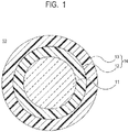
- FIG. 1 is a sectional view of a coated optical fiber 10 according to the present embodiment.
- the coated optical fiber 10 has a glass optical fiber 11 and a two-layered coating layer 14 including a primary layer 12 (primary coating layer) that is a soft material layer and a secondary layer 13 (secondary coating layer) that is a hard material layer coated on the outer circumference of the glass optical fiber 11.
- primary layer 12 primary coating layer
- secondary layer 13 secondary coating layer
- the primary layer 12 is a flexible soft material layer having a Young's modulus that is larger than or equal to 0.2 MPa and smaller than or equal to 3.0 MPa, preferably having a Young's modulus that is larger than or equal to 0.3 MPa and smaller than or equal to 1.5 MPa.
- the secondary layer 13 is a hard material layer, which is relatively hard, having a Young's modulus that is larger than or equal to 500 MPa and smaller than or equal to 2500 MPa, preferably having a Young's modulus that is larger than or equal to 800 MPa and smaller than or equal to 1800 MPa.
- Each of the primary layer 12 and the secondary layer 13 is formed of a layer formed by irradiating a coating material for an optical fiber containing an ultraviolet curable resin with ultraviolet light for curing, and has a function of protecting the glass optical fiber 11.
- the coated optical fiber 10 is not limited to the configuration illustrated in FIG. 1 .
- the coating layer 14 may be formed of a single layer having a Young's modulus that is larger than or equal to 0.2 MPa and smaller than or equal to 1500 MPa, preferably a Young's modulus that is larger than or equal to 30 MPa and smaller than or equal to 1000 MPa.
- the coating layer 14 may include three or more layers.
- the coated optical fiber 10 may take a form of an optical fiber core further including a colored layer coated on the outer circumference of the coating layer 14.
- the coated optical fiber 10 may take a form of an optical fiber tape core further having a collective coating layer used for bundling a plurality of coated optical fibers 10.
- the diameter of the glass optical fiber 11 is typically larger than or equal to 80 ⁇ m and smaller than or equal to 150 ⁇ m, and generally larger than or equal to 124 ⁇ m and smaller than or equal to 126 ⁇ m.
- the thickness of the primary layer 12 is typically greater than or equal to 5 ⁇ m and less than or equal to 50 ⁇ m.
- the thickness of the secondary layer 13 is typically thicker than or equal to 5 ⁇ m and thinner than or equal to 50 ⁇ m.
- the diameter of the coated optical fiber 10 (that is, the outer diameter of the secondary layer 13) is typically thicker than or equal to 245 ⁇ m and thinner than or equal to 255 ⁇ m.
- the coating material for an optical fiber according to the present embodiment is used as a coating material of the coating layer 14, and at least one of the layers forming the coating layer 14 is formed of the coating material for an optical fiber according to the present embodiment.
- the coating material for an optical fiber according to the present embodiment is preferably used as a coating material of the primary layer 12 or a coating material of a coating layer in contact with the glass optical fiber 11, such as the coating layer 14 formed of a single layer, for example.
- the coating material of the coating layer 14 as a coating material for an optical fiber according to the present embodiment will be described in detail below.
- coating material of the coating layer 14 can mean a coating material of the primary layer 12 when the coating layer 14 includes the primary layer 12 and the secondary layer 13 and can mean a coating material of the coating layer 14 of interest when the coating layer 14 is formed of a single layer.
- the coating material of the coating layer 14 contains an ultraviolet curable resin.
- the ultraviolet curable resin included in the coating material for an optical fiber is not particularly limited as long as it can be polymerized by light.
- the ultraviolet curable resin may be a resin that can be polymerized by photoradical polymerization or the like, for example.
- the ultraviolet curable resin may be an ultraviolet curable resin having a polymerizable unsaturated group such as an ethylenic unsaturated group polymerized and cured by an ultraviolet light such as urethane (meth)acrylates such as polyether-based urethane (meth)acrylates and polyester-based urethane (meth)acrylates, epoxy (meth)acrylates, polyester (meth)acrylates, or the like, for example, and it is preferable that the resin have at least two polymerizable unsaturated groups.
- urethane (meth)acrylates such as polyether-based urethane (meth)acrylates and polyester-based urethane (meth)acrylates
- epoxy (meth)acrylates polyester (meth)acrylates, or the like, for example, and it is preferable that the resin have at least two polymerizable unsaturated groups.
- a polymerizable unsaturated group in the ultraviolet curable resin may be, for example, a group having an unsaturated double bond such as a vinyl group, an allyl group, an acryloyl group, a methacryloyl group, or the like, a group having an unsaturated triple bond such as a propargyl group, or the like.
- the acryloyl group and the methacryloyl group are preferable out of the groups described above in terms of polymerizability.
- the ultraviolet curable resin may be a monomer, an oligomer, or a polymer that initiates polymerization by ultraviolet irradiation to be cured and preferably is an oligomer. Note that the oligomer is a polymer having a degree of polymerization of 2 to 100.
- the term "(meth)acrylates" means one or both of acrylates and methacrylates.
- Polyether-based urethane (meth)acrylate is a compound having a polyether segment, (meth)acrylate, and a urethane bond as with a product in a reaction of polyol having a polyether framework with an organic polyisocyanate compound and hydroxyalkyl (meth)acrylate.
- polyester-based urethane (meth)acrylate is a compound having a polyester segment, (meth)acrylate, and a urethane bond as with a product in a reaction of polyol having a polyester framework with an organic polyisocyanate compound and hydroxyalkyl (meth)acrylate.
- the ultraviolet curable resin may include, for example, a diluent monomer, a photosensitizer, a chain transfer agent, and various additives in addition to an oligomer and a photopolymerization initiator.
- a diluent monomer monofunctional (meth)acrylate, or polyfunctional (meth)acrylate is used.
- the diluent monomer here means a monomer used for diluting an ultraviolet curable resin.
- Monofunctional (meth)acrylate or polyfunctional (meth)acrylate as a diluent monomer may be the followings.
- di(meth)acrylate such as butanediol di(meth)acrylate, hexanediol di(meth)acrylate, ethoxylated hexanediol di(meth)acrylate, propoxylated hexanediol di(meth)acrylate, diethyleneglycol di(meth)acrylate, polyethyleneglycol di(meth)acrylate, polypropyleneglycol di(meth)acrylate, neopentylglycol di(meth)acrylate, ethoxylated neopentylglycol di(meth)acrylate, hydroxypivalic acid neopentylglycol di(meth)acrylate, or the like; mono(meth)acrylate such as 2-hydroxyethyl (meth)acrylate, 2-
- the diluent monomers described above may be used, or two or more types of the diluent monomers may be used in combination.
- the addition amount of the diluent monomer is preferably less than or equal to 100 parts by mass, more preferably 10 to 70 parts by mass with respect to an oligomer of 100 parts by mass.
- the coating material of the coating layer 14 contains a silane coupling agent that interacts with the surface of the glass optical fiber 11 by hydrolysis and dehydration condensation and an acid generator that generates an acid such as a Lewis acid, a Br ⁇ nsted acid, or the like by the application of energy.
- the acid generated from an acid generator facilitates hydrolysis and dehydration condensation of a silane coupling agent, and adhesion between the resin included in the coating layer 14 and the glass optical fiber 11 is improved.
- An acid generator that generates an acid by application of energy is, specifically, a photoacid generator that generates an acid by light irradiation or a thermal acid generator that generates an acid by heat.
- the coating material of the coating layer 14 contains at least one of a photoacid generator and a thermal acid generator.
- the coating material of the coating layer 14 may contain both of a photoacid generator and a thermal acid generator.
- the photoacid generator and the thermal acid generator included in the coating material of the coating layer 14 will be described below in the order.
- a photoacid generator generates an acid by absorbing an irradiation light (generally, an ultraviolet light), subsequently being decomposed, and removing hydrogen from a solvent or the photoacid generator itself.
- the light absorbed by the photoacid generator is different in accordance with the type of photoacid generator and is an ultraviolet light in a wavelength region that is approximately longer than or equal to 10 nm and shorter than or equal to 405 nm, for example. It is preferable that the wavelength region of the light used for curing the ultraviolet curable resin included in the coating material of the coating layer 14 and the wavelength region of the light used for causing the photoacid generator to generate an acid at least partially overlap each other. Thereby, the curing of the ultraviolet curable resin and the generation of an acid by the photoacid generator can be simultaneously performed by using a light from a single light source.
- the photoacid generator that can be used as the coating material of the coating layer 14 is not particularly limited as long as the agent generates an acid by light irradiation.
- Photoacid generators can be roughly classified into onium salt-based photoacid generators and nonionic photoacid generators. In the present embodiment, while at least one of the onium salt-based photoacid generator and the nonionic photoacid generator is used, other types of photoacid generators may be used.
- An onium salt-based photoacid generator that can be used as the coating material of the coating layer 14 may be, but not particularly limited to, an organic sulfonium salt compound, an organic iodonium salt compound, an organic oxonium salt compound, an organic ammonium salt compound, or an organic phosphonium salt compound, which has a counter anion such as a hexafluoroantimonate anion, a tetrafluoroborate anion, a hexafluorophosphate anion, a hexachloroantimonate anion, a trifluoromethanesulfonate ion, a fluorosulfonate ion, or the like, for example.
- a counter anion such as a hexafluoroantimonate anion, a tetrafluoroborate anion, a hexafluorophosphate anion, a hexachloroantimonate anion, a trifluorome
- the counter anion is, for example, B(C 6 F 5 ) 4 - , SbF 6 - , SbF 4 - , AsF 6 - , PF 6 - , BF 4 - , CF 3 SO 3 - , or the like.
- One type of the above may be used, or two or more types of the above may be mixed and used.
- a commercially available onium salt-based photoacid generator may be, for example, IRGACURE (registered trademark, hereafter, omitted) 250, IRGACURE 270, IRGACURE PAG 290, GSID 26-1 (so far, manufactured by BASF, product name), WPI-113, WPI-116, WPI-116, WPI-169, WPI-170, WPI-124 , WPAG-336, WPAG-367, WPAG-370, WPAG-469, WPAG-638 (so far, manufactured by Wako Pure Chemical Industries, Ltd., product name), B2380, B2381, C1390, D2238, D2248, D2253, 10591, N1066, T1608, T1609, T2041, T2042 (so far, manufactured by Tokyo Chemical Industry Co., Ltd., product name), CPI-100, CPI-100P, CPI-101A, CPI-200K, CPI-210S, IK-1, IK-2, CPI-310
- a nonionic photoacid generator that can be used as the coating material of the coating layer 14 may be, but not particularly limited to, a phenacyl sulfone type photoacid generator, an o-nitrobenzyl ester type photoacid generator, an iminosulfonate type photoacid generator, a sulfonic acid ester type photoacid generator of N-hydroxyimide, or the like, for example.
- a phenacyl sulfone type photoacid generator an o-nitrobenzyl ester type photoacid generator, an iminosulfonate type photoacid generator, a sulfonic acid ester type photoacid generator of N-hydroxyimide, or the like, for example.
- One type of the above may be used, or two or more types of the above may be mixed and used.
- a specific compound of the nonionic photoacid generator may be, for example, sulfonyl diazomethane, oxime sulfonate, imidosulfonate, 2-nitrobenzylsulfonate, disulfone, pyrogallolsulfonate, p-nitrobenzyl-9,10-dimethoxyanthracene-2-sulfonate, N-sulfonylphenylsulfonamide, trifluoromethanesulfonic acid-1, 8-naphthalimide, nonafluorobutanesulfonic acid-1,8-naphthalimide, perfluorooctanesulfonic acid-1,8-naphthalimide, pentafluorobenzenesulfonic acid-1,8-naphthalimide, nonafluorobutanesulfonic acid-1,3,6-trioxo-3,6-dihydro-1H-11-thia-azacyclopentaanth
- a commercially available nonionic photoacid generator may be, for example, WPAG-145, WPAG-149, WPAG-170, WPAG-199 (so far, manufactured by Wako Pure Chemical Industries, Ltd., product name), D2963, F0362, M1209, M1245 (so far, manufactured by Tokyo Kasei Kogyo Co., Ltd., product name), SP-082, SP-103, SP-601, SP-606 (so far, manufactured by ADEKA Corporation, product name), SIN-11 (manufactured by San-Apro Ltd., product name), NT-1TF (manufactured by San-Apro stock Company-made, product name) or the like.
- a thermal acid generator is used as a thermal latent cationic initiator for thermal curing of an epoxy resin or the like and is decomposed to generate an acid when heated at a temperature higher than or equal to a predetermined temperature.
- the acid generation temperature (decomposition temperature) of a thermal acid generator used in the present embodiment which is different in accordance with the type of thermal acid generator, is preferably higher than or equal to 60 degrees Celsius and lower than or equal to 200 degrees Celsius, particularly preferably higher than or equal to 80 degrees Celsius and lower than or equal to 150 degrees Celsius in order to reduce influence on the coating optical fiber 10.
- the thermal acid generator that can be used as the coating material of the coating layer 14 is not particularly limited as long as the agent generates an acid by thermal decomposition.
- an onium salt thermal acid generator such as an organic onium salt-based compound in which a cationic component and an anionic component are paired is used as a thermal acid generator.
- a cationic component of the thermal acid generator may be, for example, an organic sulfonium salt compound, an organic oxonium salt compound, an organic ammonium salt compound, an organic phosphonium salt compound, an organic iodonium salt compound, or the like.
- an anionic component of the thermal acid generator may be, for example, B(C 6 F 5 ) 4 - , SbF 6 - , SbF 4 - , AsF 6 - , PF 6 - , BF 4 - , CF 3 SO 3 - , or the like.
- an organometallic complex such as an aluminum chelate complex, an iron-allene complex, a titanocene complex, an allylsilanol-aluminum complex, or the like, an oxime sulfonate-based acid generator, diazomethane-based acid generator such as bis(alkyl) or bis(arylsulfonyl)diazomethanes, poly(bis(sulfonyl))diazomethanes, or the like, a nitrobenzyl sulfonate-based acid generator, an iminosulfonate-based acid generator, a disulfone-based acid generator, or the like functions as a thermal acid generator.
- One type of the above may be used, or two or more types of the above may be mixed and used.
- a commercially available thermal acid generator may be, for example, K-PURE (registered trademark, hereinafter, omitted) CXC-1612, K-PURE CXC-1613, K-PURE CXC-1614, K-PURE CXC-1738, K-PURE CXC-2700, K-PURE TAG-2689, K -PURE TAG-2681, K-PURE TAG-2685, K-PURE TAG-2690, K-PURE TAG-2712, K-PURE TAG-2713 (so far, manufactured by KING INDUSTRIES, product name), San-Aid SI-45L, San-Aid SI-60L, San-Aid SI-80L, San-Aid SI-100L, San-Aid SI-110L, San-Aid SI-150L, San-Aid SI-300, San-Aid SI-360, San-Aid SI-B2A, San-Aid SI-B3A, San
- Each addition amount of the photoacid generator and the thermal acid generator which is an acid generator that generates an acid by application of energy described above, can be set as described below.
- the addition amount of the photoacid generator is preferably larger than or equal to 0.01 wt%, more preferably larger than or equal to 0.1 wt% with respect to the coating material of the coating layer 14.
- the photoacid generator is less than the preferable amount, the progression rate of a hydrolysis reaction and a dehydration condensation reaction of the silane coupling agent decreases due to a reduction in the amount of acid generated from the photoacid generator, and development of adhesiveness between the coating layer 14 and the glass optical fiber 11 takes time.
- wt% indicates a concentration in percent by weight (the same applies below).
- the addition amount of the photoacid generator is preferably smaller than or equal to the addition amount of the photopolymerization initiator described below included in the coating material of the coating layer 14, more preferably smaller than the addition amount of the photopolymerization initiator.
- the photoacid generator is added more than the photopolymerization initiator, since the reaction of the photopolymerization initiator, which also absorbs ultraviolet light and generates radical species, is inhibited, curability of the coating layer 14 may decrease, and the elastic modulus may decrease.
- the addition amount of the photoacid generator is preferably smaller than or equal to 10 wt%, more preferably smaller than or equal to 5 wt% with respect to the coating material of the coating layer 14.
- sufficient curability of the primary layer 12 corresponds to a state where the primary layer 12 has the Young's modulus that is larger than or equal to 0.2 MPa and smaller than or equal to 3.0 MPa, preferably larger than or equal to 0.3 MPa and smaller than or equal to 1.5 MPa after curing so that the coated optical fiber 10 maintains the characteristics and the function.
- the addition amount of the thermal acid generator is preferably larger than or equal to 0.01 wt% and smaller than or equal to 10 wt%, more preferably larger than or equal to 0.1 wt% and smaller than or equal to 5 wt% with respect to the coating material of the coating layer 14.
- a smaller amount than such a preferable range facilitating effect for hydrolysis and polycondensation reaction of the silane coupling agent decreases due to a reduction in the amount of the generated acid, and development of adhesiveness between the coating layer 14 (primary layer 12) and the glass optical fiber 11 takes time.
- storage stability of the coating material may decrease.
- the photoacid generator and the thermal acid generator described above may be used in combination with each other.
- the excessive addition of a photoacid generator may inhibit a reaction of a photopolymerization initiator described below, which similarly absorbs ultraviolet light and generates radical species. Accordingly, by using a photoacid generator and a thermal acid generator in combination, it is possible to compensate the effect of a photoacid generator while suppressing inhibition of a reaction of a photopolymerization initiator.
- the addition amount of the acid generator in the coating material of the coating layer 14 is preferably smaller than or equal to the amount of photopolymerization initiator, more preferably smaller than the addition amount of the photopolymerization initiator.
- an addition amount of an acid generator here means an addition amount of a photoacid generator when the photoacid generator out of the photoacid generator and the thermal acid generator is added alone, and an addition amount of a thermal acid generator when the thermal acid generator out of the photoacid generator and the thermal acid generator is added alone.
- an addition amount of an acid generator here means the total addition amount of a photoacid generator and a thermal acid generator when the photoacid generator and the thermal acid generator are used in combination.
- An addition amount of a photoacid generator when added alone is defined as described above.
- an acid may occur during storage, which may facilitate a polycondensation reaction of a silane coupling agent and reduce long term storage stability of a coating material.
- the total addition amount of the photoacid generator and the thermal acid generator be smaller than or equal to the addition amount of a photopolymerization initiator so as to reduce influence of the photoacid generator and the thermal acid generator on the photopolymerization initiator.
- the reaction of a silane coupling agent can be facilitated by adding at least one of light and heat during manufacture of the optical fiber. Furthermore, the generated acid enables the reaction of the epoxy group of an epoxy compound to proceed. Since substantially no acid is generated from the photoacid generator and the thermal acid generator without addition of light and heat, it is easy to handle the coating material.
- a thermal acid generator can generate an acid due to heat from the light source during curing of an ultraviolet curable resin or reaction heat of the resin itself without requiring an additional special step. Further, a heating step to generate an acid from a thermal acid generator may be set separately. In such a case, as with heat aging described below, a device used for heating an optical fiber core after an ultraviolet curable resin is cured may be installed in the post-stage of an ultraviolet irradiation apparatus, or the manufactured optical fiber core may be set inside a thermostatic incubator to perform heat aging. It is therefore possible to accelerate improvement of adhesiveness between the coating layer 14 and the glass optical fiber 11.
- the acid generation temperature (decomposition temperature) of a thermal acid generator is preferably from 60 to 200 degrees Celsius and particularly preferably from 80 to 150 degrees Celsius as described above.
- the addition amount of the thermal acid generator is preferably smaller than or equal to 10 wt% with respect to the coating material of the coating layer 14 and more preferably less than the addition amount of the photoacid generator.
- the coating material of the coating layer 14 contains an epoxy compound that is a compound having an epoxy group that performs an acid catalytic reaction.
- an epoxy compound a ring cleavage reaction of an epoxy group occurs in which an acid generated from a photoacid generator or a thermal acid generator serves as a catalyst, and a hydroxyl group is generated.
- the hydroxyl group generated by the ring cleavage reaction of the epoxy group forms a covalent bond or a hydrogen bond with a hydroxyl group on the surface of the glass optical fiber 11 to interact with the surface of the glass optical fiber 11, for example.
- adhesion between the resin contained in the coating layer 14 (primary layer 12) and the glass optical fiber 11 is improved.
- an epoxy compound be a compound having a chemical structure or a functional group that reacts or interacts with an ultraviolet curable resin separately from the epoxy group that reacts by an acid catalyst.
- an epoxy compound be a compound that is incorporated into an ultraviolet curable resin by a radical polymerization reaction or an ene-thiol reaction.
- an epoxy compound be a compound that has a photopolymerizable functional group and is radically polymerized by radicals generated from the photopolymerization initiator by ultraviolet light irradiation.
- a photopolymerizable functional group may be, for example, an acryloyl group, a methacryloyl group, a maleimide group, a styryl group, a maleic anhydride residue, a vinyl ether group, an allyl ether group, an alkenyl group having 2 to 10 carbon atoms, an alkynyl group having 2 to 10 carbon atoms, or the like, and a (meth)acryloyl group is preferable.
- (meth)acryloyl group means one or both of an acryloyl group and an methacryloyl group.
- an epoxy compound By having a photopolymerizable functional group, an epoxy compound is incorporated into polymer chains in a reaction with oligomers of the ultraviolet curable resin by radical polymerization. Thereby, the reaction between the epoxy groups of the epoxy compounds due to an acid generated from a photoacid generator is inhibited, for example, by a steric hindrance or the like, and as a result, interaction between a hydroxyl group derived from an epoxy group and the surface of the glass optical fiber 11 preferentially occurs.
- An epoxy compound may be preferably, but not particularly limited to, a compound with an epoxy group and a photopolymerizable functional group, for example, glycidyl (meth)acrylate, methyl glycidyl (meth)acrylate, 4-hydroxybutyl (meth)acrylate glycidy ether, 3,4-epoxybutyl (meth)acrylate, 3-methyl-3,4-epoxybutyl (meth)acrylate , 3-ethyl-3,4-epoxybutyl (meth)acrylate, 4-methyl-4,5-epoxypentyl (meth)acrylate, 5-methyl-5,6-epoxyhexyl(meth)acrylate, ⁇ -ethyl acrylic acid glycidyl, allyl glycidyl ether, crotonyl glycidyl ale, (iso)crotonic acid glycidyl ether, (3,4-epoxycyclohexyl)methyl
- an epoxy compound not only a monomer but also a polymer or an oligomer may be used as long as it does not impair the compatibility.
- a polymer or an oligomer may be, for example, copolymers of monomers of epoxy group compounds and various vinyl monomers each having a photopolymerizable functional group, and specifically may be, for example, Marproof G-0115S, Marproof G-0130S, Marproof G-0250S, Marproof G-0150M, Marproof G-1005S, Marproof G01010S, Marproof G-1005SA, Marproof G-01100 (so far, manufactured by NOF Corporation, product name), ARUFON UG-4010, ARUFON UG-4035, ARUFON UG-4040, ARUFON UG-4070 (so far, manufactured by Toagosei Co., Ltd. product name), Epofriend AT501, Epofriend CT310 (so far, manufactured by Daicel Corporation. product name), or the like as a commercially available copolymer
- the addition amount of the epoxy compound is preferably an amount such that the concentration of an epoxy group is larger than or equal to 0. 1 mmol/g and smaller than or equal to 5.0 mmol/g, more preferably an amount such that the concentration of an epoxy group is larger than or equal to 0. 2 mmol/g and smaller than or equal to 2.5 mmol/g with respect to the coating material of the coating layer 14.
- the addition amount of the epoxy compound is smaller than this preferable range, adhesiveness between the coating layer 14 and the glass optical fiber 11 decreases due to the reduced reaction amount of an acid catalysis of an epoxy group or development of adhesiveness takes time.
- the term "concentration of an epoxy group” means a value obtained by dividing the value of milli moles (mmol) of an epoxy group of an epoxy compound by the value of grams (g) of a coating material resin composition.
- the addition amount of the epoxy compound may be determined such that the concentration of an epoxy group is in the range described above with respect to the coating material of the coating layer 14. Specifically, the addition amount of the epoxy compound is preferably larger than or equal to 0. 5 wt% and smaller than or equal to 80 wt%, more preferably larger than or equal to 1.0 wt% and smaller than or equal to 20 wt% with respect to 100 wt% of the coating material of the coating layer 14. The addition amount of the epoxy compound can be adjusted in accordance with the physical property of the target coating layer 14.
- the addition amount of the epoxy compound is smaller than such a preferable range, since the amount of the hydroxyl groups generated by a ring cleavage reaction of the epoxy group is reduced, development of adhesiveness between the coating layer 14 and the glass optical fiber 11 takes time.
- the addition amount of the epoxy compound is larger than this preferable range, there is a concern about a reaction between the epoxy groups.
- silane coupling agent any agent including agents generally known and commonly used may be used as long as it does not impair the effects of the present invention.
- the addition amount of the silane coupling agent is approximately determined in accordance with experiments or the like.
- a specific compound as a silane coupling agent may be, but not particularly limited to, tetramethyl silicate, tetraethyl silicate, vinyl trichloro silane, vinyl trimethoxy silane, vinyl triethoxy silane, 2-(3,4-epoxycyclohexyl) ethyl trimethoxy silane, 3-glycidoxy propyl methyl dimethoxy silane, 3-glycidoxy propyl trimethoxy silane, 3-glycidoxy propyl methyl diethoxy silane, 3-glycidoxy propyl triethoxy silane, p-styryl trimethoxy silane, 3-methacryloxy propyl methyl dimethoxy silane, 3-methacryloxy propyl trimeth
- the addition amount of the silane coupling agent is preferably larger than or equal to 0. 1 wt% and smaller than or equal to 10 wt%, more preferably larger than or equal to 0.5 wt% and smaller than or equal to 5.0 wt% with respect to the coating layer 14.
- the silane coupling agent is in the range described above, sufficient adhesion between the glass optical fiber 11 and the coating layer 14 is obtained, and good storage stability of the coating material is obtained.
- the coating material of the coating layer 14 may contain a diluent monomer, a photopolymerization initiator, a photosensitizer, a chain transfer agent, and various additives.
- a diluent monomer monofunctional (meth)acrylate or polyfunctional (meth)acrylate is used.
- the diluent monomer is a monomer used for diluting the ultraviolet curable resin.
- a photopolymerization initiator initiates polymerization of an ultraviolet curable resin by absorbing a light in the wavelength region emitted from an ultraviolet irradiation apparatus and generating radicals.
- the type of photopolymerization initiator is not particularly limited and may be suitably selected.
- photopolymerization initiator for example, but not particularly limited to, benzyl ketal-based photopolymerization initiator, ⁇ -hydroxyketone-based photopolymerization initiator, ⁇ -aminoketone-based photopolymerization initiator, acylphosphine oxide-based photopolymerization initiator, oxime ester-based photopolymerization initiator, acridine-based photopolymerization initiator, benzophenone-based photopolymerization initiator, acetophenone-based photopolymerization initiator, aromatic ketoester-based photopolymerization initiator, benzoic ester-based photopolymerization initiator, or the like may be used.
- a benzylketal-based photopolymerization initiator may be 2,2-dimethoxy-1,2-diphenylethane-1-one, for example.
- An ⁇ -hydroxyketone-based photopolymerization initiator may be 1-(4-isopropylphenyl)-2-hydroxy-2-methylpropan-1-one, 2-hydroxy-2-methyl-1-phenylpropane-1-one, 1-hydroxycyclohexyl phenylketone, 1-[4-(2-hydroxyethoxy)phenyl]-2-hydroxy-2-methylpropane-1-one, 2-hydroxy-1-[4-[4-(2-hydroxy-2-methylpropionyl)benzyl]phenyl]-2-methylpropane-1-one, for example.
- a ⁇ -aminoketone-based photopolymerization initiator may be, for example, 2-dimethylamino-2-methyl-1-phenylpropane-1-one, 2-diethylamino-2-methyl-1-phenylpropane-1-one, 2-methyl-2-morpholino-1-phenylpropane-1-one, 2-dimethylamino-2-methyl-1-(4-methylphenyl)propane-1-one, 2-dimethylamino-1-(4-ethylphenyl)-2-methylpropane-1-one, 2-dimethylamino-1-(4-isopropylphenyl)-2-methylpropane-1-one, 1-(4-butylphenyl)-2-dimethylamino-2-methylpropane-1-one, 2-dimethylamino-1-(4-methoxyphenyl)-2-methylpropane-1-one, 2-dimethylamino-2-methyl-1-(4-methylthiophenyl
- An acylphosphine oxide-based photopolymerization initiator may be, for example, 2,4,6-trimethylbenzoyl-diphenylphosphine oxide, bis(2,4,6-trimethylbenzoyl)-phenylphosphine oxide, bis(2,6-dimethoxybenzoyl)-(2,4,4-trimethylpentyl)phosphine oxide.
- An oxime ester-based photopolymerization initiator may be, for example, 1-phenylpropane-1,2-dione-2-(O-ethoxycarbonyl)oxime, 1-phenylbutane-1,2-dione-2-(O-methoxycarbonyl)oxime, 1,3-diphenylpropane-1,2,3-trione-2-(O-ethoxycarbonyl)oxime, 1-[4-(phenylthio)phenyl]octane-1,2-dione-2-(O-benzoyl)oxime, 1-[4-[4-(carboxyphenyl)thio]phenyl]propane-1,2-dione-2-(O-acetyl)oxime, 1-[9-ethyl-6-(2-methylbenzoyl)-9H-carbazol-3-yl]ethanone-1-(O-acetyl)oxime, 1-[9-ethyl-6-[2-methyl-4-[1
- An acridine-based photopolymerization initiator may be 1,7-bis(acridin-9-yl)-n-heptane, for example.
- a benzophenone-based photopolymerization initiator may be, for example, benzophenone, 4,4'-bis (dimethylamino)benzophenone, 4,4'-bis(diethylamino)benzophenone, 4-phenylbenzophenone, 4,4'-dichlorobenzophenone, 4-hydroxybenzophenone, alkylated benzophenone, 3,3',4,4'-tetrakis(t-butylperoxycarbonyl)benzophenone, 4-methylbenzophenone, dibenzylketone, fluorenone.
- An acetophenone-based photopolymerization initiator may be, for example, 2,2-diethoxy acetophenone, 2,3-diethoxy acetophenone, 4-t-butyldichloro acetophenone, benzal acetophenone, 4-azidobenzal acetophenone.
- An aromatic ketoester-based photopolymerization initiator may be methyl 2-phenyl-2-oxyacetate, for example.
- a benzoic ester-based photopolymerization initiator may be, for example, ethyl (4-dimethylamino)benzoate, (2-ethyl)hexyl 4-(dimethylamino)benzoate, ethyl (4-diethylamino)benzoate, methyl (2-benzoyl)benzoate.
- a commercially available photopolymerization initiator may be IRGACURE (registered trademark, hereinafter, omitted) 651, IRGACURE 184, IRGACURE 1173, IRGACURE 2959, IRGACURE 127, IRGACURE 907, IRGACURE 369, IRGACURE 379, IRGACURE TPO, IRGACURE 819, IRGACURE OXE01, IRGACURE OXE02, IRGACURE MBF, IRGACURE 754 (so far, manufactured by BASF Corp., product name), Adeka Akruz (registered trademark) NCI-831 (manufactured by ADEKA, product name), or the like.
- IRGACURE registered trademark, hereinafter, omitted
- the addition amount of the photopolymerization initiator is preferably larger than or equal to 0. 01 wt% and smaller than or equal to 10 wt%, more preferably larger than or equal to 0.1 wt% and smaller than or equal to 8 wt% with respect to the coating material of the coating layer 14.
- the addition amount of the photopolymerization initiator is excessively small, since the reaction rate of radical polymerization, that is, the curing rate of the generated resin composition becomes slow, the curing is likely to take time, or the curing characteristics are likely to decrease.
- an excessive amount of the photopolymerization initiator may reduce curability in the depth of a resin layer.
- a photosensitizer is added to the coating material of the coating layer 14 for the purpose of improving photosensitivity of a photoacid generator. It is preferable that a photosensitizer be a substance that absorbs light in a wavelength region different from that of the photoacid generator. A photosensitizer improves photosensitivity of the photoacid generator by absorbing light in the wavelength region in which the photoacid generator cannot absorb the light. Therefore, the absorption wavelength region of a photosensitizer and the absorption wavelength region of a photoacid generator are different from each other, and it is more preferable that there be less overlap therebetween.
- the addition amount of the photosensitizer is preferably larger than or equal to 0. 1 wt% and smaller than or equal to 10 wt%, more preferably larger than or equal to 0.5 wt% and smaller than or equal to 10 wt% with respect to the coating material of the coating layer 14.
- the addition amount of the photosensitizer is larger than or equal to 0.1 wt%, a desired sensitivity is easily obtained, and when the addition amount of the photosensitizer is smaller than or equal to 10 wt%, transparency of a coating film is easily ensured.
- a photosensitizer that can be used for a coating material of the coating layer 14 may be, but not particularly limited to, anthracene derivative, benzophenone derivative, thioxanthone derivative, anthraquinone derivative, benzoin derivative, or the like, for example.
- a specific compound of photosensitizers may be, but not particularly limited to, 9,10-dialkoxy anthracene, 2-alkyl thioxanthone, 2,4-dialkyl thioxanthone, 2-alkyl anthraquinone, 2,4-dialkyl anthraquinone, p,p'-diamino benzophenone, 2-hydroxy-4-alkoxy benzophenone, benzoin ether, anthrone, anthracene, 9,10-diphenyl anthracene, 9-ethoxy anthracene, pyrene, perylene, coronene, phenanthrene, benzophenone, benzyl, benzoin, methyl (2-benzoyl)benzoate, butyl (2-benzoyl)benzoate, benzoin ethylether, benzoin-i-butylether, 9-fluorenone, acetophenone, p,p'-t
- a heater apparatus used for heating a coated optical fiber or an optical fiber core after the resin curing is performed is installed in the post-stage of an ultraviolet irradiation apparatus, and heat aging can be performed by using the heater apparatus. Further, heat aging can be performed by placing the manufactured optical fiber core in a thermostatic incubator. In such a way, it is possible to accelerate the improvement of adhesiveness between the coating layer 14 and the glass optical fiber 11.
- FIG. 2 is a schematic diagram of a manufacturing apparatus 20 used for a manufacturing method of the coated optical fiber 10 according to the present embodiment.
- an optical fiber base material 21 is made of a quartz glass and is manufactured by a known method such as a VAD method, an OVD method, a MCVD method, or the like.
- the end of the optical fiber base material 21 is heated and melted by using a heater 22 that is a heater apparatus arranged around the optical fiber base material 21, and a glass optical fiber 23 (that is the glass optical fiber 11 in FIG. 1 ) is drawn by drawing.
- a resin application apparatus 24 that applies an ultraviolet curable resin on the outer circumference of the glass optical fiber 23 is provided under the heater 22.
- the resin application apparatus 24 separately holds a coating material used for the primary layer 12 (referred to as a primary layer material) and a coating material used for the secondary layer 13 (referred to as a secondary layer material).
- at least the primary layer material is a coating material used for an optical fiber according to the present embodiment containing the silane coupling agent, at least one of the photoacid generator and the thermal acid generator, and the epoxy compound described above.
- the secondary layer material is not limited to the configuration described above and may not contain a silane coupling agent, a photoacid generator, a thermal acid generator, and an epoxy compound, for example.
- the primary layer material and the secondary layer material are collectively applied to the glass optical fiber 23 drawn from the optical fiber base material 21 by the resin application apparatus 24.
- An ultraviolet irradiation apparatus 26 that irradiates the glass optical fiber 25 coated with the primary layer material and the secondary layer material with an ultraviolet light is provided under the resin application apparatus 24.
- the ultraviolet irradiation apparatus 26 has any ultraviolet source such as a semiconductor light emitting device, a mercury lamp, or the like.
- the glass optical fiber 25 to which the ultraviolet curable resin is applied by the resin application apparatus 24 enters the ultraviolet irradiation apparatus 26 and is irradiated with the ultraviolet light.
- two layers of ultraviolet curable resins coated on the outer circumference of the glass optical fiber 25 are cured, and the two layers of ultraviolet curable resins become the primary layer 12 and the secondary layer 13.
- a coating material used for the coating layer 14 contains at least one of the photoacid generator and the thermal acid generator.
- the coating material contains a photoacid generator
- an acid is generated from the photoacid generator contained in the coating material by ultraviolet irradiation by the ultraviolet irradiation apparatus 26.
- the coating material contains a thermal acid generator
- an acid is generated from the thermal acid generator contained in the coating material due to heat from the light source included in the ultraviolet irradiation apparatus 26 or the reaction heat of the resin itself.
- a heat source such as a heater may be provided in the ultraviolet irradiation apparatus 26, and heating may be performed simultaneously with ultraviolet irradiation.
- the glass optical fiber (that is, the coated optical fiber 10) having the outer circumference on which the primary layer 12 and the secondary layer 13 are formed is guided by a guide roller 27 and wound by a winding apparatus 28.
- the Wet-On-Wet method in which the primary layer 12 and the secondary layer 13 are applied by one die and cured is used
- the Wet-On-Dry method in which the primary layer 12 and the secondary layer 13 are applied by separate dies and cured may be used.
- FIG. 3 is a diagram illustrating a flowchart of a manufacturing method of the coated optical fiber 10 according to the present embodiment.
- the user sets the optical fiber base material 21 in the manufacturing apparatus 20 (step S11).
- the heater 22 heats the optical fiber base material 21, and drawing of the glass optical fiber 23 is started (step S12).
- the resin application apparatus 24 coats the drawn glass optical fiber 23 with the primary layer material (step S13) and then coats the drawn glass optical fiber 23 with the secondary layer material (step S14).
- the ultraviolet irradiation apparatus 26 irradiates the glass optical fiber 25 coated with the primary layer material and the secondary layer material with an ultraviolet light and simultaneously performs heating (step S15).
- the primary layer material and the secondary layer material are cured by ultraviolet irradiation, and the coated optical fiber 10 having the primary layer 12 and the secondary layer 13 is formed.
- An acid is generated from the photoacid generator contained in the coating material by ultraviolet irradiation by using the ultraviolet irradiation apparatus 26, and an acid is generated from the thermal acid generator contained in the coating material by heat from the light source included in the ultraviolet irradiation apparatus 26 or the reaction heat of the resin itself. That is, in the present embodiment, a step of curing the ultraviolet curable resin by ultraviolet irradiation by using the ultraviolet irradiation apparatus 26 also functions as a step of generating an acid from the photoacid generator and generating an acid from the thermal acid generator.
- a heating step is included in an ultraviolet irradiation step.
- the coating material used for the coating layer 14 (in particular, the primary layer 12) of the coated optical fiber 10 according to the present embodiment contains at least one of the photoacid generator and the thermal acid generator.
- the coating material contains a photoacid generator
- the photoacid generator since the photoacid generator generates an acid only after ultraviolet irradiation, an acid is generated simultaneously with the ultraviolet curing of the coating material.
- the coating material contains a thermal acid generator
- the thermal acid generator since the thermal acid generator generates an acid only after heating, an acid is generated by reaction heat at the ultraviolet curing of the coating material or heating after the ultraviolet irradiation.
- the generated acid facilitates the progress of a hydrolysis reaction and a dehydration condensation reaction of the silane coupling agent.
- the generated acid serves as a catalyst
- a hydroxyl group is produced by a ring cleavage reaction of an epoxy group of an epoxy compound, and the produced hydroxyl group interacts with the surface of the glass optical fiber 11. According to the results above, high adhesiveness between the glass optical fiber 11 and the coating layer 14 is obtained.
- the photoacid generator generates an acid by absorbing ultraviolet light emitted from the ultraviolet irradiation apparatus 26 to cure the ultraviolet curable resin and being decomposed. Therefore, when the coating material contains a photoacid generator, it is not necessary to add or change a manufacturing process.
- the thermal acid generator may be decomposed by heat from the light source included in the ultraviolet irradiation apparatus 26 or the reaction heat of the resin itself and generate an acid. Therefore, even when the coating material contains a thermal acid generator, it is not necessarily to need to add or change a manufacturing process.
- optical loss is increased by water infiltration in a conventional optical fiber core.
- interface adhesion between the glass optical fiber and the primary layer is reduced by the water infiltration causing a partial peeling, water is accumulated in a space formed accordingly, and the peeling is further extended, for example.
- a peeling occurs at the interface between the glass optical fiber and the primary layer, and water is accumulated, which provides a side pressure to the glass optical fiber, and causes occurrence of an increase in optical loss due to a micro bending. Since the adhesiveness at the interface between the glass optical fiber and the primary layer is improved in the optical fiber core using the coated optical fiber 10 according to the present embodiment, an increase of optical loss due to water infiltration in the optical fiber core can be suppressed.
- the adhesiveness at the interface between the glass optical fiber and the primary layer is improved in the coated optical fiber 10 according to the present embodiment, endurance (represented by dynamic fatigue characteristics) of breaking strength of the glass optical fiber 11 can be stably maintained over a long period of time.
- the coating material according to the present embodiment In a configuration in which an acid or basic coating material is prepared in advance to facilitate the reaction of the silane coupling agent, there is a problem of natural progress of a reaction of a silane coupling agent during storage.
- the coating material according to the present embodiment generates substantially no acid from the photoacid generator when stored in a dark place. Further, the coating material according to the present embodiment generates substantially no acid from the thermal acid generator when stored in a cool dark place. Therefore, the coating material according to the present embodiment has good storage stability.
- a heating step separated from an ultraviolet irradiation step is performed in the present embodiment.
- the heating step decomposes the thermal acid generator to generate an acid.
- the heating step is performed at any timing before, on, or after the coating step of applying the ultraviolet resin to the glass optical fiber to the ultraviolet irradiation step for the curing as long as it can heat the coating material.
- the coating step, the heating step, and the ultraviolet irradiation step may be performed in this order, and the order may be changed. Further, all or some of the coating step, the heating step, and the ultraviolet irradiation step may be repeated. Further, the coating step and the heating step may be simultaneously performed, or the heating step and the ultraviolet irradiation step may be simultaneously performed.
- FIG. 4 to FIG. 6 are schematic diagrams of the manufacturing apparatus 20 used for the manufacturing method of the coated optical fiber 10 according to the present embodiment.
- a heater apparatus 29 used for heating the coating material at a location is different from each other.
- the heater apparatus 29 having a cylindrical shape is provided under the ultraviolet irradiation apparatus 26.
- the heater apparatus 29 performs heating when the glass optical fiber 25 that has been irradiated with the ultraviolet light by the ultraviolet irradiation apparatus 26 passes inside.
- the heater apparatus 29 is provided so as to surround the sides of the resin application apparatus 24.
- the heater apparatus 29 heats the coating material by heating a die of the resin application apparatus 24, and the resin application apparatus 24 coats the glass optical fiber 23 with the heated coating material.
- a heater apparatus 29 having a cylindrical shape is provided between the resin application apparatus 24 and the ultraviolet irradiation apparatus 26.
- the heater apparatus 29 performs heating when the glass optical fiber 25 that has been coated with the coating material by the resin application apparatus 24 passes inside.
- Each heater apparatus 29 of FIG. 4 to FIG. 6 has any heat source such as a tape heater, a ribbon heater, a rubber heater, an oven heater, a ceramic heater, an infrared irradiation unit, an ultraviolet irradiation unit, a heating wire heater, a carbon heater, a halogen heater, or the like.
- the heating temperature by the heater apparatus 29 is preferably higher than or equal to 60 degrees Celsius and lower than or equal to 200 degrees Celsius, particularly preferably higher than or equal to 80 degrees Celsius and lower than or equal to 150 degrees Celsius.
- FIG. 7 is a diagram illustrating a flowchart of the manufacturing method of the coated optical fiber 10 using the manufacturing apparatus 20 of FIG. 4 .
- the steps S11 to S15 are the same as those of the first embodiment.
- the heater apparatus 29 heats the coated optical fiber 10 (that is, the coating material of the coating layer 14) at a predetermined temperature (step S16).
- the heating step (step S16) and the coating steps (steps S13 to S14) are performed at the same time in the flowchart in FIG. 7 .
- the heating step (step S16) is performed between the coating steps (steps S13 to S14) and the ultraviolet irradiation step (step S15).
- the coating step, the ultraviolet irradiation step, and the heating step is performed once, at least one of these steps may be repeated twice or more.
- the coating material contains a thermal acid generator
- the coating material is heated up to the decomposition temperature of the thermal acid generator in the heating step to generate an acid.
- This facilitates a hydrolysis reaction and a dehydration condensation reaction of a silane coupling agent and causes a ring cleavage reaction of an epoxy group of an epoxy compound to progress.
- the hydrolysis and the dehydration condensation of the silane coupling agent or acid catalytic reaction of the epoxy group by the acid generated from the photoacid generator or the thermal acid generator is facilitated by the heat in the heating step.
- high adhesiveness between the glass optical fiber 11 and the coating layer 14 can be obtained.
- the heating step may be performed after the coated optical fiber 10 is manufactured. Specifically, after the coated optical fiber 10 is manufactured by the manufacturing method according to the first embodiment, the coated optical fiber 10 may be heated by being placed in a thermostatic incubator set to a predetermined temperature. In such a way, an advantage of improving interface adhesion by heating can be obtained without a change in the manufacturing apparatus 20 from the first embodiment.
- an ultraviolet curable resin used for the coating material an ultraviolet curable polyether-based urethane acrylate-based resin was used.
- the Young's modulus is adjusted to be 1.0 MPa by changing the molecular weight of the polyether moiety in the oligomer, or the type and the formation amount of diluent monomers and reactive monomers.
- a photopolymerization initiator 3.0 wt% of Lucirin (registered trademark) TPO (manufactured by BASF, product name) are used, and as a silane coupling agent, 1.5 wt% of KBM-5103 (manufactured by Shin-Etsu Chemical Co., Ltd., product name) was used.
- a photoacid generator to be added to the coating material 4-isobutyl phenyl(4-methylphenyl)iodonium hexafluorophosphate (manufactured by BASF, product name IRGACURE 250) was used. Further, as a thermal acid generator to be added to the coating material, 1-naphthyl methyl methyl-p-hydroxyphenylsulfonium hexafluoroantimonate (manufactured by Sanshin Chemical Industry Co., Ltd., product name San-Aid SI-60L, decomposition temperature is 60 degrees Celsius) was used.
- the addition amount of IRGACURE 250 was 0.3 wt% when used alone, and the addition amount of IRGACURE 250 was 0.2 wt% when used in combination with SI-60L.
- the addition amount of SI-60L was 0.3 wt% when used alone, and the addition amount of SI-60L was 0.1 wt% when used in combination with IRGACURE 250.
- glycidyl methacrylate manufactured by Tokyo Chemical Industry Co., Ltd.
- the coating material according to each Example and Comparative Example was spin-coated by a thickness of 100 ⁇ m on a plate-shaped glass substrate.
- the fabricated sample was put in a purge box to be provided with a nitrogen atmosphere and was irradiated with ultraviolet light with the illuminance and the rate being adjusted so that the integrated light quantity was 500 mJ/cm 2 (measurement wavelength of 365 nm, electrodeless UV lamp, D bulb) by a conveyer type ultraviolet irradiation apparatus.
- the coating material cured in such a way was used as the film according to each Example and Comparative Example.
- the Young's modulus (tensile resilient modulus) of the film was used to determine the curability of the coating material.
- Each film according to Examples and Comparative Examples was peeled off from the glass substrate and cut into a strip of a width of 6 mm, and the 2.5%-modulus thereof was measured conforming to JIS K7161.
- glass adhesion was used.
- the film according to each Example and Comparative Example was cut into a width of 10 mm, and force needed when the film was peeled from the glass surface by pulling the film in a direction of 90 degrees from the surface of the glass substrate at a rate of 50 mm/min at the room temperature was measured as the glass adhesion.
- the measurement was performed under three conditions of 1 day, 3 days, and 14 days after film fabrication.
- Examples 1 to 6 compared to Comparative Example 1 in which neither the photoacid generator nor the epoxy compound is added and Comparative Examples 2 and 3 in which either one is not added, it was confirmed that the glass adhesion is improved by using the photoacid generator and the epoxy compound in combination. Further, in Examples 1 to 6, it was also confirmed that the glass adhesion tends to increase as the addition amount of the epoxy compound increases.
- thermo acid generator generated an acid by using the heat of the reaction of the resin at the ultraviolet irradiation and the heat from the irradiation apparatus.
- Example 9 it was confirmed that even when the photoacid generator and the thermal acid generator are used in combination, the same advantageous effect as when one of them is added can be obtained.
- Comparative Example 1 it was confirmed that, when neither the acid generator nor the epoxy compound is added, while a certain degree of glass adhesion is developed by the action of the silane coupling agent, it takes time before the development thereof.
- Comparative Example 2 it was confirmed that, although the addition of the photoacid generator accelerates the development of the glass adhesion and improves the glass adhesion compared to Comparative Example 1, the glass adhesion is smaller than that of each Example in which the epoxy compound is also added.
Landscapes
- Chemical & Material Sciences (AREA)
- Life Sciences & Earth Sciences (AREA)
- Engineering & Computer Science (AREA)
- Organic Chemistry (AREA)
- Materials Engineering (AREA)
- Geochemistry & Mineralogy (AREA)
- Chemical Kinetics & Catalysis (AREA)
- General Chemical & Material Sciences (AREA)
- General Life Sciences & Earth Sciences (AREA)
- Physics & Mathematics (AREA)
- Optics & Photonics (AREA)
- Wood Science & Technology (AREA)
- General Physics & Mathematics (AREA)
- Manufacturing & Machinery (AREA)
- Surface Treatment Of Glass Fibres Or Filaments (AREA)
- Optical Fibers, Optical Fiber Cores, And Optical Fiber Bundles (AREA)
Applications Claiming Priority (2)
| Application Number | Priority Date | Filing Date | Title |
|---|---|---|---|
| JP2017161399 | 2017-08-24 | ||
| PCT/JP2018/012794 WO2019038977A1 (ja) | 2017-08-24 | 2018-03-28 | 光ファイバ用被覆材料、被覆光ファイバ、及び被覆光ファイバの製造方法 |
Publications (2)
| Publication Number | Publication Date |
|---|---|
| EP3674272A1 true EP3674272A1 (de) | 2020-07-01 |
| EP3674272A4 EP3674272A4 (de) | 2021-03-17 |
Family
ID=65438617
Family Applications (1)
| Application Number | Title | Priority Date | Filing Date |
|---|---|---|---|
| EP18849000.7A Pending EP3674272A4 (de) | 2017-08-24 | 2018-03-28 | Beschichtungsmaterial für optische faser, beschichtete optische faser und verfahren zur herstellung einer beschichteten optischen faser |
Country Status (4)
| Country | Link |
|---|---|
| US (1) | US20200181417A1 (de) |
| EP (1) | EP3674272A4 (de) |
| JP (1) | JP7129414B2 (de) |
| WO (1) | WO2019038977A1 (de) |
Families Citing this family (1)
| Publication number | Priority date | Publication date | Assignee | Title |
|---|---|---|---|---|
| JPWO2024162068A1 (de) * | 2023-01-30 | 2024-08-08 |
Family Cites Families (17)
| Publication number | Priority date | Publication date | Assignee | Title |
|---|---|---|---|---|
| JPS5992947A (ja) | 1982-11-20 | 1984-05-29 | Nippon Telegr & Teleph Corp <Ntt> | 光学ガラスフアイバ用被覆材料 |
| US5181269A (en) * | 1991-09-17 | 1993-01-19 | At&T Bell Laboratories | Optical fiber including acidic coating system |
| JPH09243870A (ja) * | 1996-03-14 | 1997-09-19 | Hitachi Ltd | 光モジュール製造方法 |
| AU2001271237A1 (en) | 2000-05-01 | 2001-11-12 | Corning Incorporated | Optical fiber coating |
| EP1432857A1 (de) | 2001-09-07 | 2004-06-30 | Borden Chemical, Inc. | Beschichtete lichtleiter mit haftvermittlern, deren herstellung und verwendung |
| US20050215655A1 (en) * | 2004-03-29 | 2005-09-29 | Bilodeau Wayne L | Anaerobic pressure sensitive adhesive |
| US20110318882A1 (en) * | 2010-06-24 | 2011-12-29 | Xiaoming Wu | Method of restricting chip movement upon bonding to rigid substrate using spray coatable adhesive |
| JP5867749B2 (ja) * | 2011-03-23 | 2016-02-24 | 日産化学工業株式会社 | 多官能エポキシ化合物 |
| JP2013091575A (ja) | 2011-10-24 | 2013-05-16 | Sumitomo Electric Ind Ltd | 光ファイバ素線の製造方法及びその製造方法により得られた光ファイバ素線 |
| JP2013107293A (ja) * | 2011-11-21 | 2013-06-06 | Sumitomo Bakelite Co Ltd | 透明複合基板および表示素子基板 |
| JP5794387B2 (ja) * | 2012-04-10 | 2015-10-14 | ダイキン工業株式会社 | インプリント用樹脂モールド材料組成物 |
| US9557477B2 (en) * | 2012-06-22 | 2017-01-31 | Sumitomo Electric Industries, Ltd. | Coated optical fiber |
| JP2014156522A (ja) * | 2013-02-15 | 2014-08-28 | Toyo Ink Sc Holdings Co Ltd | 熱硬化性組成物 |
| US9322986B2 (en) * | 2013-06-24 | 2016-04-26 | Corning Incorporated | Optical fiber coating for short data network |
| JP6331526B2 (ja) * | 2014-03-14 | 2018-05-30 | オムロン株式会社 | 樹脂組成物およびその硬化物 |
| EP3161081B1 (de) * | 2014-06-27 | 2019-01-16 | Corning Incorporated | Uv-härtbare beschichtungszusammensetzungen für glas auf der basis von epoxid-/oxetanverbindungen, epoxidfunktionalisiertem silsesquioxan und epoxidfunktionalisierten nanopartikeln |
| ES2629062B1 (es) * | 2015-12-22 | 2018-06-08 | Bsh Electrodomésticos España, S.A. | Proceso para fabricar un componente de aparato doméstico |
-
2018
- 2018-03-28 EP EP18849000.7A patent/EP3674272A4/de active Pending
- 2018-03-28 WO PCT/JP2018/012794 patent/WO2019038977A1/ja not_active Ceased
- 2018-03-28 JP JP2019537908A patent/JP7129414B2/ja active Active
-
2020
- 2020-02-12 US US16/788,361 patent/US20200181417A1/en not_active Abandoned
Also Published As
| Publication number | Publication date |
|---|---|
| JP7129414B2 (ja) | 2022-09-01 |
| EP3674272A4 (de) | 2021-03-17 |
| WO2019038977A1 (ja) | 2019-02-28 |
| US20200181417A1 (en) | 2020-06-11 |
| JPWO2019038977A1 (ja) | 2020-08-06 |
Similar Documents
| Publication | Publication Date | Title |
|---|---|---|
| US7923480B2 (en) | Photocurable hygroscopic composition and organic EL device | |
| JP5311744B2 (ja) | 紫外線硬化性樹脂組成物、当該硬化物、およびこれらから誘導される各種物品 | |
| JP6106253B1 (ja) | 光ファイバテープ、光ファイバテープの製造方法、及び間欠固定型光ファイバテープの連結部の形成に用いられる紫外線硬化樹脂組成物 | |
| CN105324240A (zh) | 透明导电性层叠膜、其制造方法及触摸面板 | |
| JP6055914B2 (ja) | 絶縁材料用組成物 | |
| JP5561189B2 (ja) | 感放射線性組成物、硬化膜及びその形成方法 | |
| JP2019056106A (ja) | 活性エネルギー線硬化性組成物 | |
| WO2022203081A1 (ja) | 光硬化性樹脂組成物、光学部品、光学部品の製造方法、及び発光装置 | |
| KR20170129725A (ko) | 경화성 조성물 | |
| TW202111010A (zh) | 壓印用樹脂組成物 | |
| US20200181417A1 (en) | Coating material for optical fiber, coated optical fiber, and manufacturing method of coated optical fiber | |
| JP2011202070A (ja) | 硬化性樹脂組成物及びその硬化物 | |
| EP1724316A1 (de) | Strahlungshärtbare beschichtungszusammensetzung und verfahren zur herstellung eines schützenden überzugs | |
| JP2011006620A (ja) | ハードコート用組成物 | |
| JP2018112624A (ja) | 感光性樹脂組成物 | |
| JP5702951B2 (ja) | 光ファイバ心線 | |
| JP6774916B2 (ja) | 光ファイバ用被覆材料、被覆光ファイバ、及び被覆光ファイバの製造方法 | |
| JP2018052762A (ja) | 光ファイバ用被覆材料、被覆光ファイバ、及び被覆光ファイバの製造方法 | |
| JP2004285119A (ja) | 熱硬化性および活性エネルギー線硬化性樹脂組成物とその硬化方法 | |
| JP2021075656A (ja) | ケイ素含有反応物 | |
| KR101736237B1 (ko) | 감방사선성 조성물, 보호막 및 층간 절연막 및, 그들의 형성 방법 | |
| TWI815191B (zh) | 樹脂組成物以及硬化膜 | |
| US20250147230A1 (en) | Optical fiber and method for manufacturing optical fiber | |
| WO2022071446A1 (ja) | 撥水レンズ保護膜用樹脂組成物及び撥水レンズを保護する方法 | |
| WO2022130855A1 (ja) | 樹脂組成物、光ファイバのセカンダリ被覆材料、光ファイバ及び光ファイバの製造方法 |
Legal Events
| Date | Code | Title | Description |
|---|---|---|---|
| STAA | Information on the status of an ep patent application or granted ep patent |
Free format text: STATUS: THE INTERNATIONAL PUBLICATION HAS BEEN MADE |
|
| PUAI | Public reference made under article 153(3) epc to a published international application that has entered the european phase |
Free format text: ORIGINAL CODE: 0009012 |
|
| STAA | Information on the status of an ep patent application or granted ep patent |
Free format text: STATUS: REQUEST FOR EXAMINATION WAS MADE |
|
| 17P | Request for examination filed |
Effective date: 20200210 |
|
| AK | Designated contracting states |
Kind code of ref document: A1 Designated state(s): AL AT BE BG CH CY CZ DE DK EE ES FI FR GB GR HR HU IE IS IT LI LT LU LV MC MK MT NL NO PL PT RO RS SE SI SK SM TR |
|
| AX | Request for extension of the european patent |
Extension state: BA ME |
|
| DAV | Request for validation of the european patent (deleted) | ||
| DAX | Request for extension of the european patent (deleted) | ||
| REG | Reference to a national code |
Ref country code: DE Ref legal event code: R079 Free format text: PREVIOUS MAIN CLASS: C03C0025400000 Ipc: C03C0025106000 |
|
| A4 | Supplementary search report drawn up and despatched |
Effective date: 20210212 |
|
| RIC1 | Information provided on ipc code assigned before grant |
Ipc: C03C 25/40 20060101ALI20210208BHEP Ipc: C09D 183/00 20060101ALI20210208BHEP Ipc: G02B 6/44 20060101ALI20210208BHEP Ipc: C03C 25/106 20180101AFI20210208BHEP Ipc: C03C 25/36 20060101ALI20210208BHEP |
|
| STAA | Information on the status of an ep patent application or granted ep patent |
Free format text: STATUS: EXAMINATION IS IN PROGRESS |
|
| 17Q | First examination report despatched |
Effective date: 20240604 |